JP2005292638A - Developing device, image forming apparatus, and image forming system - Google Patents
Developing device, image forming apparatus, and image forming system Download PDFInfo
- Publication number
- JP2005292638A JP2005292638A JP2004110086A JP2004110086A JP2005292638A JP 2005292638 A JP2005292638 A JP 2005292638A JP 2004110086 A JP2004110086 A JP 2004110086A JP 2004110086 A JP2004110086 A JP 2004110086A JP 2005292638 A JP2005292638 A JP 2005292638A
- Authority
- JP
- Japan
- Prior art keywords
- developer
- roller
- developer supply
- developing device
- supply roller
- Prior art date
- Legal status (The legal status is an assumption and is not a legal conclusion. Google has not performed a legal analysis and makes no representation as to the accuracy of the status listed.)
- Pending
Links
- 239000007788 liquid Substances 0.000 claims abstract description 96
- 230000001105 regulatory effect Effects 0.000 claims description 23
- 230000006866 deterioration Effects 0.000 abstract description 8
- 238000004140 cleaning Methods 0.000 description 20
- 108091008695 photoreceptors Proteins 0.000 description 17
- 238000010586 diagram Methods 0.000 description 12
- 230000000694 effects Effects 0.000 description 10
- 239000010410 layer Substances 0.000 description 10
- 230000006870 function Effects 0.000 description 8
- XEEYBQQBJWHFJM-UHFFFAOYSA-N Iron Chemical compound [Fe] XEEYBQQBJWHFJM-UHFFFAOYSA-N 0.000 description 6
- 229920001971 elastomer Polymers 0.000 description 5
- 239000010408 film Substances 0.000 description 4
- 239000000463 material Substances 0.000 description 4
- 229920006311 Urethane elastomer Polymers 0.000 description 3
- 230000009471 action Effects 0.000 description 3
- 230000002411 adverse Effects 0.000 description 3
- 229910052742 iron Inorganic materials 0.000 description 3
- 230000002093 peripheral effect Effects 0.000 description 3
- 230000005684 electric field Effects 0.000 description 2
- 230000008030 elimination Effects 0.000 description 2
- 238000003379 elimination reaction Methods 0.000 description 2
- 239000004973 liquid crystal related substance Substances 0.000 description 2
- 239000002184 metal Substances 0.000 description 2
- 229910052751 metal Inorganic materials 0.000 description 2
- 238000006386 neutralization reaction Methods 0.000 description 2
- 239000002245 particle Substances 0.000 description 2
- 238000007790 scraping Methods 0.000 description 2
- 230000003068 static effect Effects 0.000 description 2
- 239000002344 surface layer Substances 0.000 description 2
- 239000010409 thin film Substances 0.000 description 2
- 239000005662 Paraffin oil Substances 0.000 description 1
- 230000008901 benefit Effects 0.000 description 1
- 230000015556 catabolic process Effects 0.000 description 1
- 239000003795 chemical substances by application Substances 0.000 description 1
- 238000006731 degradation reaction Methods 0.000 description 1
- 239000004744 fabric Substances 0.000 description 1
- 230000001678 irradiating effect Effects 0.000 description 1
- 230000007246 mechanism Effects 0.000 description 1
- 230000003287 optical effect Effects 0.000 description 1
- 239000000123 paper Substances 0.000 description 1
- 239000000049 pigment Substances 0.000 description 1
- 239000011347 resin Substances 0.000 description 1
- 229920005989 resin Polymers 0.000 description 1
- 230000004044 response Effects 0.000 description 1
- 230000000717 retained effect Effects 0.000 description 1
- 239000004065 semiconductor Substances 0.000 description 1
- 229920002545 silicone oil Polymers 0.000 description 1
- 238000003756 stirring Methods 0.000 description 1
- 238000011144 upstream manufacturing Methods 0.000 description 1
Images


Landscapes
- Wet Developing In Electrophotography (AREA)
Abstract
【課題】画質の劣化を適切に防止する現像装置、画像形成装置、及び、画像形成システムを実現することにある。
【解決手段】液体現像剤を担持するための現像剤担持体と、液体現像剤を前記現像剤担持体に供給するための回転可能な現像剤供給部材と、液体現像剤を収容するための現像剤収容体と、を有し、前記現像剤担持体に担持された液体現像剤によって、像担持体に担持された潜像を現像する現像装置であって、前記現像剤供給部材が、その一部が露出した状態で、前記現像剤収容体に収容された液体現像剤に浸っている現像装置において、前記現像剤供給部材に対向し、かつ、前記現像剤収容体に接するように設けられ、前記現像剤供給部材の回転方向と同方向に回転することにより前記現像剤収容体に対し摺動する摺動ローラを有することを特徴とする。
【選択図】 図7
A developing device, an image forming apparatus, and an image forming system that appropriately prevent deterioration in image quality are provided.
A developer carrying member for carrying a liquid developer, a rotatable developer supply member for feeding the liquid developer to the developer carrying member, and a development for containing the liquid developer. A developing device for developing a latent image carried on the image carrier by a liquid developer carried on the developer carrier, wherein the developer supply member includes In the developing device immersed in the liquid developer accommodated in the developer container with the portion exposed, the developer device is provided so as to face the developer supply member and to contact the developer container. It has a sliding roller which slides with respect to the developer container by rotating in the same direction as the rotation direction of the developer supply member.
[Selection] Figure 7
Description
本発明は、現像装置、画像形成装置、及び、画像形成システムに関する。 The present invention relates to a developing device, an image forming apparatus, and an image forming system.
この種の画像形成装置としては、例えば、潜像を担持するための像担持体の一例としての感光体と、液体現像剤(以下、単に、現像剤とも呼ぶ)によって感光体に担持された潜像を現像するための現像装置と、を有する画像形成装置が知られている。かかる画像形成装置は、ホストコンピュータなどの外部装置から画像信号等が送信されると、感光体上に潜像を形成する。そして、感光体に形成され、担持された潜像は、感光体の回転に伴って現像位置に至り、現像装置によって現像され、感光体上に現像剤像が形成される。 As this type of image forming apparatus, for example, a photoconductor as an example of an image carrier for carrying a latent image and a latent image carried on the photoconductor by a liquid developer (hereinafter also simply referred to as a developer). 2. Description of the Related Art An image forming apparatus having a developing device for developing an image is known. Such an image forming apparatus forms a latent image on a photoreceptor when an image signal or the like is transmitted from an external device such as a host computer. Then, the latent image formed and carried on the photosensitive member reaches the developing position as the photosensitive member rotates, and is developed by the developing device, so that a developer image is formed on the photosensitive member.
上記の現像装置は、感光体上に形成された潜像を現像するという既述の機能等を実現するために、現像剤を担持するための現像剤担持体の一例としての現像ローラと、現像剤を現像ローラに供給するための回転可能な現像剤供給部材の一例としての現像剤供給ローラと、現像剤を収容するための現像剤収容体の一例としての現像剤収容部と、を有している。 In order to realize the above-described function of developing the latent image formed on the photosensitive member, the developing device described above includes a developing roller as an example of a developer carrying member for carrying the developer, and development. A developer supply roller as an example of a rotatable developer supply member for supplying the developer to the developing roller, and a developer container as an example of a developer container for containing the developer. ing.
そして、現像剤供給ローラは、その一部が露出した状態で、現像剤収容部に収容された現像剤に浸っており、現像剤供給ローラが回転することにより、前記現像剤が現像ローラに供給される。さらに、現像ローラに供給された現像剤は、潜像の現像に供される。
現像剤供給ローラが、その一部が露出した状態で、現像剤収容部に収容された現像剤に浸っている状況で、現像剤供給ローラが回転すると、現像剤供給ローラが現像剤に進入する際に空気が取り込まれて、現像剤内に気泡が発生する場合がある。
当該気泡を有する現像剤が現像ローラに供給され、供給された現像剤により、感光体に担持された潜像を現像して画像を形成した場合には、その画質に劣化が生ずる可能性がある。
When the developer supply roller rotates while the developer supply roller is immersed in the developer accommodated in the developer accommodating portion with a part thereof exposed, the developer supply roller enters the developer. In some cases, air is taken in and bubbles are generated in the developer.
When the developer having the bubbles is supplied to the developing roller, and the latent image carried on the photosensitive member is developed by the supplied developer to form an image, the image quality may be deteriorated. .
本発明は、かかる課題に鑑みてなされたものであり、その目的とするところは、画質の劣化を適切に防止する現像装置、画像形成装置、及び、画像形成システムを実現することにある。 SUMMARY An advantage of some aspects of the invention is that it realizes a developing device, an image forming apparatus, and an image forming system that appropriately prevent deterioration in image quality.
主たる本発明は、液体現像剤を担持するための現像剤担持体と、液体現像剤を前記現像剤担持体に供給するための回転可能な現像剤供給部材と、液体現像剤を収容するための現像剤収容体と、を有し、前記現像剤担持体に担持された液体現像剤によって、像担持体に担持された潜像を現像する現像装置であって、前記現像剤供給部材が、その一部が露出した状態で、前記現像剤収容体に収容された液体現像剤に浸っている現像装置において、前記現像剤供給部材に対向し、かつ、前記現像剤収容体に接するように設けられ、前記現像剤供給部材の回転方向と同方向に回転することにより前記現像剤収容体に対し摺動する摺動ローラを有することを特徴とする現像装置である。
本発明の他の特徴については、本明細書及び添付図面の記載により明らかにする。
A main aspect of the present invention is a developer carrying member for carrying a liquid developer, a rotatable developer supply member for feeding the liquid developer to the developer carrying member, and a container for containing the liquid developer. A developer container, and developing the latent image carried on the image carrier by the liquid developer carried on the developer carrier, wherein the developer supply member comprises: In a developing device immersed in a liquid developer housed in the developer container in a partially exposed state, the developing device is provided to face the developer supply member and to contact the developer container. The developing device further comprises a sliding roller that slides relative to the developer container by rotating in the same direction as the rotation direction of the developer supply member.
Other features of the present invention will become apparent from the description of the present specification and the accompanying drawings.
本明細書及び添付図面の記載により、少なくとも次のことが明らかにされる。 At least the following will be made clear by the description of the present specification and the accompanying drawings.
液体現像剤を担持するための現像剤担持体と、液体現像剤を前記現像剤担持体に供給するための回転可能な現像剤供給部材と、液体現像剤を収容するための現像剤収容体と、を有し、前記現像剤担持体に担持された液体現像剤によって、像担持体に担持された潜像を現像する現像装置であって、前記現像剤供給部材が、その一部が露出した状態で、前記現像剤収容体に収容された液体現像剤に浸っている現像装置において、前記現像剤供給部材に対向し、かつ、前記現像剤収容体に接するように設けられ、前記現像剤供給部材の回転方向と同方向に回転することにより前記現像剤収容体に対し摺動する摺動ローラを有することを特徴とする現像装置。
現像装置がこのような摺動ローラを有することにより、画質の劣化を適切に防止することが可能となる。
A developer carrying member for carrying the liquid developer, a rotatable developer supply member for feeding the liquid developer to the developer carrying member, and a developer containing member for containing the liquid developer; And a developing device that develops the latent image carried on the image carrier by the liquid developer carried on the developer carrier, and the developer supply member is partially exposed. In the developing device immersed in the liquid developer contained in the developer container, the developer supply member is provided so as to face the developer supply member and to contact the developer container. A developing device comprising a sliding roller that slides relative to the developer container by rotating in the same direction as the rotation direction of the member.
By having such a sliding roller in the developing device, it is possible to appropriately prevent deterioration in image quality.
また、前記現像剤供給部材は、現像剤供給ローラであることとしてもよい。
また、前記摺動ローラは、液体現像剤の液中に設けられており、液体現像剤を挟んで前記現像剤供給ローラに対向することとしてもよい。
また、前記摺動ローラは、その中心軸の軸方向が前記現像剤供給ローラの中心軸の軸方向に沿うように設けられ、該摺動ローラの中心軸は該現像剤供給ローラの中心軸よりも鉛直方向下方に位置することとしてもよい。
また、前記摺動ローラは、前記現像剤供給ローラの中心軸を通る鉛直面から見て、前記現像剤供給ローラが回転して液体現像剤に進入する側に設けられていることとしてもよい。
このようにすれば、像担持体に担持された潜像を現像して画像を形成する際に、気泡による悪影響をより一層受けにくくなる。
The developer supply member may be a developer supply roller.
The sliding roller may be provided in the liquid developer, and may face the developer supply roller with the liquid developer interposed therebetween.
The sliding roller is provided such that the axial direction of the central axis thereof is along the axial direction of the central axis of the developer supply roller, and the central axis of the sliding roller is greater than the central axis of the developer supply roller. May also be positioned vertically downward.
The sliding roller may be provided on a side where the developer supply roller rotates and enters the liquid developer as viewed from a vertical plane passing through the central axis of the developer supply roller.
In this way, when the latent image carried on the image carrier is developed to form an image, it is less likely to be adversely affected by bubbles.
また、前記摺動ローラが回転している状態で、前記現像剤供給ローラの回転が開始することとしてもよい。
このようにすれば、適切な液体現像剤の流れが発生している状態で、現像剤供給ローラが回転して液体現像剤に進入することとなるから、気泡を有する液体現像剤が現像剤担持体に供給されることが、より適切に防止される。
Further, the rotation of the developer supply roller may be started while the sliding roller is rotating.
In this way, the developer supply roller rotates and enters the liquid developer in a state where an appropriate liquid developer flow is generated, so that the liquid developer having bubbles is supported by the developer. It is more appropriately prevented from being supplied to the body.
また、前記現像剤収容体は、その内壁に突出部を有し、前記摺動ローラは、液体現像剤を挟んで前記現像剤供給ローラに対向し、かつ、前記突出部に接するように設けられ、前記現像剤供給ローラの回転方向と同方向に回転することにより前記突出部に対し摺動することとしてもよい。
このようにすれば、摺動ローラの大きさを変えることなく、現像剤収容体の現像剤収容スペースを広くすることができる。
The developer container has a protrusion on an inner wall thereof, and the sliding roller is provided so as to face the developer supply roller with the liquid developer interposed therebetween and to be in contact with the protrusion. The developer supply roller may be slid with respect to the protrusion by rotating in the same direction as the rotation direction of the developer supply roller.
In this way, the developer accommodating space of the developer accommodating body can be widened without changing the size of the sliding roller.
また、前記現像剤収容体は、その内壁にシール部材を有し、前記摺動ローラは、液体現像剤を挟んで前記現像剤供給ローラに対向し、かつ、前記シール部材に接するように設けられ、前記現像剤供給ローラの回転方向と同方向に回転することにより前記シール部材に対し摺動することとしてもよい。
このようにすれば、気泡の通過を防ぐことに特化したシール部材が、摺動ローラと現像剤収容体の内壁との間に位置することとなるから、摺動ローラと現像剤収容体との間に到達した気泡が当該間を通過することが、より適切に防止される。
The developer container has a seal member on an inner wall thereof, and the sliding roller is provided to face the developer supply roller with the liquid developer interposed therebetween and to be in contact with the seal member. The developer supply roller may be slid relative to the seal member by rotating in the same direction as the rotation direction of the developer supply roller.
In this way, since the seal member specialized for preventing the passage of bubbles is located between the sliding roller and the inner wall of the developer container, the sliding roller and the developer container It is more appropriately prevented that the air bubbles that have reached during the period pass between them.
また、前記現像剤供給ローラの表面に当接して、該現像剤供給ローラ上の液体現像剤の量を規制するための規制部材を有することとしてもよい。
かかる場合には、上述した効果、すなわち、画質の劣化を防止するという効果、がより有効に発揮されることとなる。
Further, a regulating member for regulating the amount of the liquid developer on the developer supply roller in contact with the surface of the developer supply roller may be provided.
In such a case, the above-described effect, that is, the effect of preventing the deterioration of the image quality is more effectively exhibited.
また、前記液体現像剤は、常温で不揮発性を有する不揮発性液体現像剤であることとしてもよい。
かかる場合には、上述した効果、すなわち、画質の劣化を防止するという効果、がより有効に発揮されることとなる。
The liquid developer may be a non-volatile liquid developer that is non-volatile at normal temperature.
In such a case, the above-described effect, that is, the effect of preventing the deterioration of the image quality is more effectively exhibited.
また、液体現像剤を担持するための現像剤担持体と、液体現像剤を前記現像剤担持体に供給するための回転可能な現像剤供給部材と、液体現像剤を収容するための現像剤収容体と、を有し、前記現像剤担持体に担持された液体現像剤によって、像担持体に担持された潜像を現像する現像装置であって、前記現像剤供給部材が、その一部が露出した状態で、前記現像剤収容体に収容された液体現像剤に浸っている現像装置において、前記現像剤供給部材に対向し、かつ、前記現像剤収容体に接するように設けられ、前記現像剤供給部材の回転方向と同方向に回転することにより前記現像剤収容体に対し摺動する摺動ローラを有し、前記現像剤供給部材は、現像剤供給ローラであり、前記摺動ローラは、液体現像剤の液中に設けられており、液体現像剤を挟んで前記現像剤供給ローラに対向し、前記摺動ローラは、その中心軸の軸方向が前記現像剤供給ローラの中心軸の軸方向に沿うように設けられ、該摺動ローラの中心軸は該現像剤供給ローラの中心軸よりも鉛直方向下方に位置し、前記摺動ローラは、前記現像剤供給ローラの中心軸を通る鉛直面から見て、前記現像剤供給ローラが回転して液体現像剤に進入する側に設けられており、前記摺動ローラが回転している状態で、前記現像剤供給ローラの回転が開始し、前記現像剤供給ローラの表面に当接して、該現像剤供給ローラ上の液体現像剤の量を規制するための規制部材を有し、前記液体現像剤は、常温で不揮発性を有する不揮発性液体現像剤であることを特徴とする現像装置も実現可能である。
このようにすれば、既述の殆どの効果を奏するため、本発明の目的がより有効に達成される。
Also, a developer carrying member for carrying the liquid developer, a rotatable developer supply member for feeding the liquid developer to the developer carrying member, and a developer containing for containing the liquid developer. A developing device for developing a latent image carried on the image carrier by a liquid developer carried on the developer carrier, wherein the developer supply member includes a part thereof In the developing device immersed in the liquid developer housed in the developer container in an exposed state, the developing device is provided so as to face the developer supply member and to be in contact with the developer container. A sliding roller that slides relative to the developer container by rotating in the same direction as the rotation direction of the developer supply member, the developer supply member is a developer supply roller, and the sliding roller is , Provided in liquid developer liquid, liquid Opposite to the developer supply roller across the image agent, the slide roller is provided such that the axial direction of the central axis thereof is along the axial direction of the central axis of the developer supply roller. A central axis is positioned vertically below the central axis of the developer supply roller, and the sliding roller is rotated by the developer supply roller as viewed from a vertical plane passing through the central axis of the developer supply roller. The developer supply roller starts rotating in a state where the sliding roller is rotating and is brought into contact with the surface of the developer supply roller. A developing device having a regulating member for regulating the amount of the liquid developer on the developer supply roller, wherein the liquid developer is a non-volatile liquid developer having a non-volatile property at room temperature is realized. Is possible.
In this way, the object of the present invention can be achieved more effectively because most of the effects described above can be achieved.
また、潜像を担持するための像担持体と、液体現像剤を担持するための現像剤担持体と、液体現像剤を前記現像剤担持体に供給するための回転可能な現像剤供給部材と、液体現像剤を収容するための現像剤収容体と、を有し、前記現像剤担持体に担持された液体現像剤によって、前記像担持体に担持された潜像を現像する現像装置であって、前記現像剤供給部材が、その一部が露出した状態で、前記現像剤収容体に収容された液体現像剤に浸っている現像装置と、を備えた画像形成装置において、前記現像剤供給部材に対向し、かつ、前記現像剤収容体に接するように設けられ、前記現像剤供給部材の回転方向と同方向に回転することにより前記現像剤収容体に対し摺動する摺動ローラを有することを特徴とする画像形成装置も実現可能である。
画像形成装置がこのような摺動ローラを有することにより、画質の劣化を適切に防止することが可能となる。
An image carrier for carrying a latent image; a developer carrier for carrying a liquid developer; and a rotatable developer supply member for supplying the liquid developer to the developer carrier. A developer container for containing a liquid developer, and developing the latent image carried on the image carrier by the liquid developer carried on the developer carrier. In the image forming apparatus, the developer supply member includes a developing device immersed in a liquid developer accommodated in the developer container with a part of the developer supply member exposed. A sliding roller is provided so as to face the member and to be in contact with the developer container, and slides relative to the developer container by rotating in the same direction as the rotation direction of the developer supply member. An image forming apparatus characterized by .
By having such a sliding roller in the image forming apparatus, it is possible to appropriately prevent deterioration in image quality.
また、コンピュータ、及び、このコンピュータに接続可能な画像形成装置であって、潜像を担持するための像担持体と、液体現像剤を担持するための現像剤担持体と、液体現像剤を前記現像剤担持体に供給するための回転可能な現像剤供給部材と、液体現像剤を収容するための現像剤収容体と、を有し、前記現像剤担持体に担持された液体現像剤によって、前記像担持体に担持された潜像を現像する現像装置であって、前記現像剤供給部材が、その一部が露出した状態で、前記現像剤収容体に収容された液体現像剤に浸っている現像装置と、を備えた画像形成装置、を有する画像形成システムにおいて、前記現像剤供給部材に対向し、かつ、前記現像剤収容体に接するように設けられ、前記現像剤供給部材の回転方向と同方向に回転することにより前記現像剤収容体に対し摺動する摺動ローラを有することを特徴とする画像形成システムも実現可能である。
画像形成システムがこのような摺動ローラを有することにより、画質の劣化を適切に防止することが可能となる。
A computer and an image forming apparatus connectable to the computer, the image carrier for carrying a latent image, the developer carrier for carrying a liquid developer, and the liquid developer A rotatable developer supply member for supplying the developer carrier, and a developer container for containing the liquid developer, and by the liquid developer carried on the developer carrier, A developing device for developing a latent image carried on the image carrier, wherein the developer supply member is immersed in a liquid developer contained in the developer container with a part thereof exposed. In the image forming system, the image forming apparatus, the image forming apparatus, and a rotation direction of the developer supply member provided to face the developer supply member and to be in contact with the developer container. Rotating in the same direction as Image forming system comprising also feasible to have a sliding roller which slides with respect to more said developer container.
By having such a sliding roller in the image forming system, it is possible to appropriately prevent deterioration in image quality.
===画像形成装置の全体構成例===
次に、図1を用いて、画像形成装置としてレーザビームプリンタ(以下、プリンタともいう)10を例にとって、その概要について説明する。図1は、プリンタ10を構成する主要構成要素を示した図である。なお、図1には、矢印にて上下方向を示しており、例えば、現像ユニット50Y、50M、50C、50Kは、プリンタ10の下部に配置されており、中間転写体70は、プリンタ10の上部に配置されている。
=== Example of Overall Configuration of Image Forming Apparatus ===
Next, an outline of a laser beam printer (hereinafter also referred to as a printer) 10 as an example of the image forming apparatus will be described with reference to FIG. FIG. 1 is a diagram illustrating main components constituting the printer 10. In FIG. 1, the vertical direction is indicated by arrows. For example, the developing
本実施の形態に係るプリンタ10は、図1に示すように、4つの現像部15Y、15M、15C、15K、中間転写体70、二次転写ユニット80を有し、さらに、不図示の定着ユニット、ユーザへの報知手段をなし液晶パネルでなる表示ユニット、及び、これらのユニット等を制御しプリンタとしての動作を司る制御ユニット100(図2)を有している。
As shown in FIG. 1, the printer 10 according to the present embodiment includes four developing
現像部15Y、15M、15C、15Kは、それぞれ、イエロー(Y)現像剤、マゼンタ(M)現像剤、シアン(C)現像剤、ブラック(K)現像剤で潜像を現像する機能を有している。現像部15Y、15M、15C、15Kの構成は同様であるので、以下、現像部15Yについて説明する。
現像部15Yは、図1に示すように、像担持体の一例としての感光体20Yの回転方向に沿って、帯電ユニット30Y、露光ユニット40Y、現像装置の一例としての現像ユニット50Y、一次転写ユニット60Y、除電ユニット73Y、感光体クリーニングユニット75Yを有している。
感光体20Yは、円筒状の基材とその外周面に形成された感光層を有し、中心軸を中心に回転可能であり、本実施の形態においては、図1中の矢印で示すように時計回りに回転する。
帯電ユニット30Yは、感光体20Yを帯電するための装置であり、露光ユニット40Yは、レーザを照射することによって帯電された感光体20Y上に潜像を形成する装置である。この露光ユニット40Yは、半導体レーザ、ポリゴンミラー、F−θレンズ等を有しており、パーソナルコンピュータ、ワードプロセッサ等の不図示のホストコンピュータから入力された画像信号に基づいて、変調されたレーザを帯電された感光体20Y上に照射する。
現像ユニット50Yは、感光体20Y上に形成された潜像を、イエロー(Y)現像剤を用いて現像するための装置である。現像ユニット50Yの詳細については後述する。
The developing
As shown in FIG. 1, the developing
The
The charging
The developing
一次転写ユニット60Yは、感光体20Yに形成されたイエロー現像剤像を中間転写体70に転写するための装置である。一次転写ユニット60Y、60M、60C、60Kにより、4色の現像剤が順次重ねて転写された場合には、中間転写体70にフルカラー現像剤像が形成される。
中間転写体70は、複数の支持ローラに張架されたエンドレスのベルトであり、感光体20Y、20M、20C、20Kと当接しながら回転駆動される。
二次転写ユニット80は、中間転写体70上に形成された単色現像剤像やフルカラー現像剤像を紙、フィルム、布等の媒体に転写するための装置である。
不図示の定着ユニットは、媒体上に転写された単色現像剤像やフルカラー現像剤像を紙等の媒体に融着させて永久像とするための装置である。
除電ユニット73Yは、一次転写ユニット60Yによって中間転写体70上に現像剤像が転写された後に、感光体20Y上の残留電荷を除去する装置である。
感光体クリーニングユニット75Yは、感光体20Yの表面に当接されたゴム製の感光体クリーニングブレード76Yを有し、一次転写ユニット60Yによって中間転写体70上に現像剤像が転写された後に、感光体20Y上に残存する現像剤を感光体クリーニングブレード76Yにより掻き落として除去するための装置である。
The
The
The
A fixing unit (not shown) is a device for fusing a single color developer image or a full color developer image transferred onto a medium onto a medium such as paper to form a permanent image.
The
The photosensitive
制御ユニット100は、図2に示すようにメインコントローラ101と、ユニットコントローラ102とで構成され、メインコントローラ101には画像信号及び制御信号が入力され、この画像信号及び制御信号に基づく指令に応じてユニットコントローラ102が前記各ユニット等を制御して画像を形成する。
As shown in FIG. 2, the
次に、このように構成されたプリンタ10の動作について、他の構成要素にも言及しつつ説明する。
まず、不図示のホストコンピュータからの画像信号及び制御信号がインターフェイス(I/F)112を介してプリンタ10のメインコントローラ101に入力されると、このメインコントローラ101からの指令に基づくユニットコントローラ102の制御により感光体20Y、20M、20C、20K、現像ユニット50Y、50M、50C、50Kに備えられた後述する現像ローラ、及び、中間転写体70等が回転する。感光体20Y、20M、20C、20Kは、回転しながら、帯電位置において帯電ユニット30Y、30M、30C、30Kにより順次帯電される。
Next, the operation of the printer 10 configured as described above will be described with reference to other components.
First, when an image signal and a control signal from a host computer (not shown) are input to the
感光体20Y、20M、20C、20Kの帯電された領域は、感光体20Y、20M、20C、20Kの回転に伴って露光位置に至り、露光ユニット40Y、40M、40C、40Kによって、イエローY、マゼンタM、シアンC、ブラックKの画像情報に応じた潜像が該領域に形成される。
感光体20Y、20M、20C、20K上に形成された潜像は、感光体20Y、20M、20C、20Kの回転に伴って現像位置に至り、現像ユニット50Y、50M、50C、50Kによって現像される。これにより、感光体20Y、20M、20C、20K上に現像剤像が形成される。
感光体20Y、20M、20C、20K上に形成された現像剤像は、感光体20Y、20M、20C、20Kの回転に伴って一次転写位置に至り、一次転写ユニット60Y、60M、60C、60Kによって、中間転写体70に転写される。この際、一次転写ユニット60Y、60M、60C、60Kには、現像剤の帯電極性とは逆の極性の一次転写電圧が印加される。この結果、各々の感光体20Y、20M、20C、20K上に形成された4色の現像剤像は、中間転写体70に重なり合って転写され、中間転写体70上にはフルカラー現像剤像が形成される。
The charged regions of the photoconductors 20Y, 20M, 20C, and 20K reach the exposure position as the
The latent images formed on the
The developer images formed on the
中間転写体70上に形成されたフルカラー現像剤像は、中間転写体70の回転に伴って二次転写位置に至り、二次転写ユニット80によって媒体に転写される。なお、媒体は、不図示の給紙トレイから、各種ローラを介して二次転写ユニット80へ搬送される(図1中の矢印は、媒体の搬送方向を表している)。また、転写動作を行う際、二次転写ユニット80は中間転写体70に押圧されるとともに二次転写電圧が印加される。
媒体に転写されたフルカラー現像剤像は、定着ユニットによって加熱加圧されて媒体に融着される。
The full color developer image formed on the
The full color developer image transferred to the medium is heated and pressed by the fixing unit and fused to the medium.
一方、感光体20Y、20M、20C、20Kは一次転写位置を経過した後に、除電ユニット73Y、73M、73C、73Kによって除電され、さらに、感光体クリーニングユニット75Y、75M、75C、75Kに支持された感光体クリーニングブレード76Y、76M、76C、76Kによって、その表面に付着している現像剤が掻き落とされ、次の潜像を形成するための帯電に備える。掻き落とされた現像剤は、感光体クリーニングユニット75Y、75M、75C、75Kが備える残存現像剤回収部に回収される。
On the other hand, the
===制御ユニットの概要===
次に、制御ユニット100の構成について図2を参照しつつ説明する。制御ユニット100のメインコントローラ101は、インターフェイス112を介してホストコンピュータと接続され、このホストコンピュータから入力された画像信号を記憶するための画像メモリ113を備えている。ユニットコントローラ102は、装置本体の各ユニット(帯電ユニット30Y、30M、30C、30K、露光ユニット40Y、40M、40C、40K、現像ユニット50Y、50M、50C、50K、一次転写ユニット60Y、60M、60C、60K、除電ユニット73Y、73M、73C、73K、感光体クリーニングユニット75Y、75M、75C、75K、二次転写ユニット80、定着ユニット、表示ユニット)と電気的に接続され、それらが備えるセンサからの信号を受信することによって、各ユニットの状態を検出しつつ、メインコントローラ101から入力される信号に基づいて、各ユニットを制御する。
=== Overview of Control Unit ===
Next, the configuration of the
===現像ユニットの構成例===
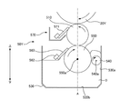
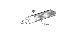
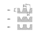
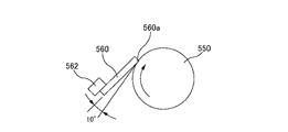
次に、図3乃至図6を用いて、現像ユニットの構成例について説明する。図3は、現像ユニットの主要構成要素を示した断面図である。図4は、現像剤供給ローラ550の表面を表した斜視概念図である。図5A乃至図5Cは現像剤供給ローラ550表面に設けられた溝の形状を示す断面図である。図6は、規制ブレード560のトレール規制を表した模式図である。なお、図3においては、図1同様、矢印にて上下方向を示しており、例えば、現像ローラ510は、現像剤供給ローラ550よりも上方にある。
=== Configuration Example of Development Unit ===
Next, a configuration example of the developing unit will be described with reference to FIGS. FIG. 3 is a cross-sectional view showing main components of the developing unit. FIG. 4 is a conceptual perspective view showing the surface of the
プリンタ10には、現像ユニットとして、ブラック(K)現像剤を収容したブラック現像ユニット50K、マゼンタ(M)現像剤を収容したマゼンタ現像ユニット50M、シアン(C)現像剤を収容したシアン現像ユニット50C、及び、イエロー(Y)現像剤を収容したイエロー現像ユニット50Yが設けられているが、各現像ユニットの構成は同様であるので、以下、イエロー現像ユニット50Yについて説明する。
The printer 10 includes, as developing units, a black developing
イエロー現像ユニット50Yは、現像剤収容体の一例としての現像剤収容部530と、現像剤供給部材の一例としての現像剤供給ローラ550と、摺動ローラ540と、規制部材の一例としての規制ブレード560と、現像剤担持体の一例としての現像ローラ510と、現像ローラクリーニングユニット570とを有している。
The yellow developing
現像剤収容部530は、感光体20Yに形成された潜像を現像するための現像剤Dを収容する。この現像剤収容部530に収容されている現像剤Dは、従来一般的に使用されている、Isopar(商標:エクソン)をキャリアとした低濃度(1〜2wt%程度)かつ低粘度の、常温で揮発性を有する揮発性液体現像剤ではなく、高濃度かつ高粘度の、常温で不揮発性を有する不揮発性液体現像剤Dである。すなわち、本実施の形態に係る液体現像剤Dは、パラフィンオイル、シリコーンオイル等の不揮発性かつ絶縁性キャリア液中に、平均粒径0.1〜5μm程度の樹脂、顔料等からなるトナー粒子を高濃度(5〜40wt%程度)に分散させた高粘度(100〜10000mPa・s程度)現像剤Dである。
The
現像剤供給ローラ550は、現像剤Dを現像ローラ510へ供給する機能を有する。この現像剤供給ローラ550は、鉄等金属性のローラの表面に図4に示すような凹部の一例としての溝550bを均一かつ螺旋状に設け、ニッケルメッキを施したものであり、その直径は約25mmである。本実施の形態における現像剤供給ローラ550は、当該溝として、図5Aに示すような台形の断面を有する溝550bを備えているが、例えば、図5Bに示すような逆三角形の断面を有する溝を備えてもよいし、図5Cに示すような半円形の断面を有する溝を備えてもよい。なお、本実施の形態における現像剤供給ローラ550の溝寸法は、図5Aに示すとおり、溝ピッチ約170μm、山幅約45μm、谷幅約30μm、溝深さ約50μmである。
The
また、現像剤供給ローラ550は、当該現像剤供給ローラ550上の現像剤Dを現像ローラ510に適切に転写するために、その表面が、当該現像ローラ510の後述する弾性体の層に圧接している。また、現像剤供給ローラ550は、その中心軸550aを中心として回転可能であり、当該中心軸550aは、現像ローラ510の回転中心軸よりも下方にある。また、現像剤供給ローラ550は、現像ローラ510の回転方向(図3において反時計方向)と逆の方向(図3において時計方向)に回転する。
Further, in order to appropriately transfer the developer D on the
さらに、現像剤供給ローラ550は、その一部が露出した状態で、現像剤収容部530に収容された現像剤Dに浸っている。したがって、かかる状況で現像剤供給ローラ550が回転すると、現像剤供給ローラ550の中心軸を通る鉛直面Aから見て図3中右側において現像剤供給ローラ550は現像剤Dに進入し、図3中左側において現像剤供給ローラ550は現像剤Dから進出することとなる。
Further, the
摺動ローラ540は、回転することにより、前記現像剤収容部530の側壁530aに対し摺動する。この摺動ローラ540は、SUS製のローラであり、その直径は約10mmである。
摺動ローラ540は、その中心軸540aの軸方向が現像剤供給ローラ550の中心軸550aの軸方向に沿うように、かつ、前述した鉛直面Aから見て、現像剤供給ローラ550が回転して現像剤Dに進入する側(すなわち、鉛直面Aから見て図3中右側)に設けられている。また、摺動ローラ540の中心軸540aは、現像剤供給ローラ550の中心軸550aよりも、鉛直方向下方に位置し、摺動ローラ540は現像剤Dの液中に設けられている。さらに、摺動ローラ540は、現像剤Dを挟んで現像剤供給ローラ550に対向し、かつ、前記現像剤収容部530の側壁530aに接している。なお、摺動ローラ540は、現像剤供給ローラ550から、約1mmの幅を持って離間している。
The sliding
The sliding
また、摺動ローラ540は、その中心軸540aを中心として回転可能であり、現像剤供給ローラ550の回転方向(図3において時計方向)と同方向(図3において時計方向)に回転する。摺動ローラ540の回転速度は、現像剤供給ローラ550の回転速度と、線速度で同速である。
なお、摺動ローラ540は、現像剤収容部530に収容されている現像剤Dを現像剤供給ローラ550へ向けて移動させることにより、現像剤Dを現像剤供給ローラ550へ供給する機能を有するとともに、現像剤Dを適正な状態に維持するために現像剤Dを撹拌する機能を有する。
Further, the sliding
The sliding
規制ブレード560は、現像剤供給ローラ550の表面に当接して、現像剤供給ローラ550上の現像剤Dの量を規制する。すなわち、当該規制ブレード560は、現像剤供給ローラ550上の余剰現像剤を掻き取って、現像ローラ510に供給する現像剤供給ローラ550上の現像剤D、を計量する役割を果たす。この規制ブレード560は、弾性体としてのウレタンゴムからなり、鉄等金属製の規制ブレード支持部材562より支持されている。また、規制ブレード560は、前述した鉛直面Aから見て、現像剤供給ローラ550が回転して現像剤Dから進出する側(すなわち、鉛直面Aから見て図3中左側)に設けられている。なお、規制ブレード560のゴム硬度は、JIS−Aで約62度であり、規制ブレード560の、現像剤供給ローラ550表面への当接部、の硬度(約62度)は、後述する現像ローラ510の弾性体の層の、現像剤供給ローラ550表面への圧接部、の硬度(約85度)よりも低くなっている。
The
また、規制ブレード560は、そのエッジ部560aが現像剤供給ローラ550の表面に当接しており、いわゆるエッジ規制を行う。また、図6に示されるように、規制ブレード560は、その先端が現像剤供給ローラ550の回転方向の下流側に向くように配置されており、いわゆるトレール規制を行う。図6に示されるように、本実施の形態において、そのトレール角度は約10度である。
Further, the
現像ローラ510は、感光体20Yに担持された潜像を現像剤Dにより現像するために、現像剤Dを担持して感光体20Yと対向する現像位置に搬送する。この現像ローラ510は、鉄等金属製の内芯の外周部に、導電性を有する弾性体の層を備えたものであり、その直径は約20mmである。また、弾性体の層は、二層構造になっており、その内層として、ゴム硬度がJIS−A約30度で、厚み約5mmのウレタンゴムが、その表層(外層)として、ゴム硬度がJIS−A約85度で、厚み約30μmのウレタンゴムが備えられている。そして、現像ローラ510は、前記表層が圧接部となって、弾性変形された状態で現像剤供給ローラ550及び感光体20Yのそれぞれに圧接している。
The developing
また、現像ローラ510は、その中心軸を中心として回転可能であり、当該中心軸は、感光体20Yの回転中心軸よりも下方にある。また、現像ローラ510は、感光体20Yの回転方向(図3において時計方向)と逆の方向(図3において反時計方向)に回転する。なお、感光体20Y上に形成された潜像を現像する際には、現像ローラ510と感光体20Yとの間に電界が形成される。
Further, the developing
現像ローラクリーニングユニット570は、現像ローラ510の表面に当接されたゴム製の現像ローラクリーニングブレード571を有し、前記現像位置で現像が行われた後に、現像ローラ510上に残存する現像剤Dを現像ローラクリーニングブレード571により掻き落として除去するための装置である。
The developing
このように構成されたイエロー現像ユニット50Yにおいて、摺動ローラ540が、その中心軸540a回りに回転することによって、現像剤収容部530に収容されている現像剤Dを現像剤供給ローラ550へ向けて移動させ、現像剤Dを現像剤供給ローラ550へ供給する。
In the yellow developing
現像剤Dは、現像剤供給ローラ550の回転によって、規制ブレード560の当接位置に至る。そして、当該当接位置を通過する際に、現像剤Dの余剰分が規制ブレード560によって掻き取られ、現像ローラ510に供給される現像剤Dの現像剤量が計量される。すなわち、現像剤供給ローラ550には、前述したとおり、溝550bが設けられているから、現像剤供給ローラ550に当接する規制ブレード560は、現像剤供給ローラ550上の現像剤Dを溝550bに保持された現像剤Dを残して掻き取ることとなる。また、現像ローラ510に供給される現像剤Dの現像剤量が適正な量になるように溝550bの寸法が決められているので、規制ブレード560が現像剤供給ローラ550上の現像剤Dを掻き取った際には、溝550bによって適正な量に計量された現像剤Dが溝550bに残存することとなる。
The developer D reaches the contact position of the
現像剤供給ローラ550の溝550bに保持された現像剤Dは、現像剤供給ローラ550のさらなる回転によって、現像ローラ510との圧接位置に至る。当該圧接位置に至った現像剤Dは、現像剤供給ローラ550と現像ローラ510が圧接することにより生ずる圧力の作用より、現像剤供給ローラ550から現像ローラ510へ転写され、現像ローラ510上には現像剤Dの薄膜が形成される。
The developer D held in the
このようにして現像ローラ510上に形成された現像剤Dの薄膜は、現像ローラ510の回転によって、感光体20Yに対向する現像位置(すなわち、感光体20Yとの圧接位置)に至り、該現像位置にて所定の大きさの電界下で感光体20Y上に形成された潜像の現像に供される。現像位置を通過した現像ローラ510上の現像剤Dは、現像ローラ510のさらなる回転によって、現像ローラクリーニングブレード571の当接位置に至る。そして、当該当接位置を通過する際に、現像ローラクリーニングブレード571によって、現像ローラ510の表面に付着している現像剤Dが掻き落とされ、掻き落とされた現像剤Dは、現像ローラクリーニングユニット570が備える残存現像剤回収部に回収される。
The developer D thin film formed on the developing
なお、現像剤供給ローラ550の回転は、摺動ローラ540が回転している状態で開始する。すなわち、プリンタ10は、摺動ローラ540を回転させた後に、現像剤供給ローラ550を回転させる。
The rotation of the
===摺動ローラの、気泡に対する作用について===
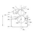
上述したとおり、本実施形態に係る摺動ローラ540は、現像剤供給ローラ550に対向し、かつ、現像剤収容部530に接するように設けられ、現像剤供給ローラ550の回転方向と同方向に回転することにより現像剤収容部530に対し摺動する。このことにより、画質の劣化を適切に防止することが可能となる。
すなわち、発明が解決しようとする課題の項等で説明したとおり、現像剤供給ローラ550が、その一部が露出した状態で、現像剤収容部530に収容された現像剤Dに浸っている状況で、現像剤供給ローラ550が回転すると、現像剤供給ローラ550が現像剤Dに進入する際に空気が取り込まれて、現像剤D内(特に、現像剤Dの、現像剤供給ローラ550が回転して進入する進入部)に気泡が発生する場合がある。
当該気泡を有する現像剤Dが現像ローラ510に供給され、供給された現像剤Dにより、感光体20Y、20M、20C、20Kに担持された潜像を現像して画像を形成した場合には、その画質に劣化が生ずる可能性がある。
=== About the action of the sliding roller against bubbles ===
As described above, the sliding
That is, as described in the section of the problem to be solved by the invention, the
When the developer D having bubbles is supplied to the developing
一例を挙げて、より具体的に説明する。現像剤D内に発生した気泡が、現像剤供給ローラ550周辺に存在する状態(例えば、現像剤供給ローラ550に付着した状態)で、現像剤供給ローラ550が回転すると、当該気泡は規制ブレード560の当接位置に至ることとなる。当該気泡は、当該当接位置に、換言すれば、規制ブレード560と現像剤供給ローラ550との間に、蓄積されるが、ときどき規制ブレード560をすり抜けて、現像ローラ510との圧接位置に至ることとなる。そして、当該圧接位置に至った気泡は、現像剤Dと共に、現像ローラ510に転写されるが、当該転写の際に、又は、転写後に、気泡が破裂する場合があり、その結果、現像ローラ510上に形成される現像剤Dの薄膜の膜厚が不均一なものとなる。したがって、かかる場合には、その膜厚が不均一な現像剤Dにより、感光体20Y、20M、20C、20Kに担持された潜像を現像して画像を形成することとなり、その画質に劣化が生ずることとなる。
An example is given and it demonstrates more concretely. When the bubbles generated in the developer D are present around the developer supply roller 550 (for example, attached to the developer supply roller 550), when the
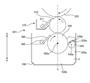
そこで、現像剤供給ローラ550の回転方向と同方向に回転することにより現像剤収容部530に対し摺動する摺動ローラ540を、現像剤供給ローラ550に対向し、かつ、現像剤収容部530に接するように設ける。
このようにすれば、摺動ローラ540が、現像剤供給ローラ550に対向した状態で現像剤供給ローラ550の回転方向と同方向に回転するから、現像剤D内に発生し現像剤供給ローラ550に付着して当該現像剤供給ローラ550の回転に伴って移動しようとする気泡や、現像剤供給ローラ550の近傍に位置し現像剤供給ローラ550が回転する方向に沿って移動しようとする気泡、の当該移動を妨げるような方向(図7中矢印Xで示す方向)に、現像剤Dの流れが発生し、当該現像剤Dの流れの作用により気泡を矢印Xの方向に移動させることが可能となる。
Therefore, the sliding
In this way, the sliding
また、摺動ローラ540の回転により、摺動ローラ540の回転する方向に沿う方向(図7中矢印Yで示す方向)にも、現像剤Dの流れが発生しうるから、当該現像剤Dの流れの作用により気泡が、矢印Yの方向に移動して摺動ローラ540と現像剤収容部530との間に到達する可能性がある。しかしながら、摺動ローラ540は、現像剤収容部530に接するように設けられ、現像剤収容部530に対し摺動するから、摺動ローラ540と現像剤収容部530との間に到達した気泡が当該間を通過することが、防止される。
Further, the rotation of the sliding
すなわち、現像剤供給ローラ550が現像剤Dに進入する際に空気が取り込まれて現像剤D内に発生した気泡が、摺動ローラ540と現像剤供給ローラ550の間及び摺動ローラ540と現像剤収容部530との間を通過することが回避され、気泡を有する現像剤Dが現像ローラ510に供給されることが適切に防止される。
したがって、気泡による前述した悪影響を受けることなく、感光体20Y、20M、20C、20Kに担持された潜像を現像して画像を形成することが可能となり、延いては、画質の劣化が適切に防止されることとなる。
なお、図7は、摺動ローラ540の回転により発生する現像剤Dの流れの例を示した模式図である。
That is, when air is taken in when the
Therefore, it is possible to form an image by developing the latent images carried on the
FIG. 7 is a schematic diagram illustrating an example of the flow of the developer D generated by the rotation of the sliding
===その他の実施の形態===
以上、上記実施の形態に基づき本発明に係る現像装置等を説明したが、上記発明の実施の形態は、本発明の理解を容易にするためのものであり、本発明を限定するものではない。本発明は、その趣旨を逸脱することなく、変更、改良され得ると共に、本発明にはその等価物が含まれることはもちろんである。
=== Other Embodiments ===
Although the developing device and the like according to the present invention have been described above based on the above embodiment, the above embodiment is for facilitating understanding of the present invention and does not limit the present invention. . The present invention can be changed and improved without departing from the gist thereof, and the present invention includes the equivalents thereof.
上記実施の形態においては、画像形成装置として中間転写型のフルカラーレーザビームプリンタを例にとって説明したが、本発明は、中間転写型以外のフルカラーレーザビームプリンタにも適用可能である。また、フルカラーレーザプリンタだけではなく、モノクロレーザビームプリンタにも適用可能である。また、プリンタだけでなく、複写機、ファクシミリなどの各種画像形成装置にも適用可能である。 In the above embodiment, an intermediate transfer type full-color laser beam printer has been described as an example of the image forming apparatus. However, the present invention is also applicable to a full-color laser beam printer other than the intermediate transfer type. Further, it is applicable not only to a full color laser printer but also to a monochrome laser beam printer. Further, it is applicable not only to a printer but also to various image forming apparatuses such as a copying machine and a facsimile.
また、感光体についても、円筒状の基材の外周面に感光層を設けて構成した、いわゆる感光ローラに限られず、ベルト状の基材の表面に感光層を設けて構成した、いわゆる感光ベルトであってもよい。 Further, the photosensitive member is not limited to a so-called photosensitive roller configured by providing a photosensitive layer on the outer peripheral surface of a cylindrical base material, and is a so-called photosensitive belt configured by providing a photosensitive layer on the surface of a belt-shaped base material. It may be.
同様に、上記実施の形態においては、前記現像剤担持体と、前記現像剤供給部材は、それぞれ、現像ローラ510と、現像剤供給ローラ550であることとしたが、これに限定されるものではなく、例えば、ベルト状の現像ベルトや現像剤供給ベルトであってもよい。
Similarly, in the above-described embodiment, the developer carrier and the developer supply member are the developing
また、上記実施の形態においては、規制ブレード560は、その先端が現像剤供給ローラ550の回転方向の下流側に向くように配置されており、いわゆるトレール規制を行うこととしたが、これに限定されるものではなく、例えば、その先端が現像剤供給ローラの回転方向の上流側に向くように配置されており、いわゆるカウンター規制を行うこととしてもよい。
Further, in the above embodiment, the
また、上記実施の形態において、摺動ローラ540は、現像剤Dの液中に設けられており、現像剤Dを挟んで現像剤供給ローラ550に対向することとしたが、これに限定されるものではない。例えば、摺動ローラ540は、現像剤Dを挟むことなく現像剤供給ローラ550に対向する(例えば、現像剤供給ローラ550に当接した状態で、現像剤供給ローラ550に対向する)こととしてもよい。
In the above embodiment, the sliding
また、上記実施の形態において、摺動ローラ540は、その中心軸540aの軸方向が現像剤供給ローラ550の中心軸550aの軸方向に沿うように設けられ、摺動ローラ540の中心軸540aは現像剤供給ローラ550の中心軸550aよりも鉛直方向下方に位置することとしたが、これに限定されるものではない。例えば、摺動ローラ540の中心軸540aが現像剤供給ローラ550の中心軸550aよりも鉛直方向上方に位置することとしてもよい。
Further, in the above embodiment, the sliding
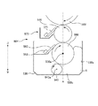
また、上記実施の形態において、摺動ローラ540は、現像剤供給ローラ550の中心軸550aを通る鉛直面Aから見て、現像剤供給ローラ550が回転して現像剤Dに進入する側に設けられていることとしたが、これに限定されるものではない。例えば、図8に示すように、摺動ローラ540は、現像剤供給ローラ550の中心軸550aを通る鉛直面Aから見て、現像剤供給ローラ550が回転して現像剤Dから進出する側に設けられていることとしてもよい。
In the above embodiment, the sliding
摺動ローラ540が、前記鉛直面Aから見て現像剤供給ローラ550が回転して現像剤Dに進入する側に設けられている場合には、現像剤Dから進出する側に設けられている場合に比べて、摺動ローラ540と現像剤供給ローラ550の間及び摺動ローラ540と現像剤収容部530との間を通過することができなかった気泡が、上方へ移動して、現像剤供給ローラ550が現像剤Dに進入する側に位置する現像剤Dの液面にて、消滅(すなわち、気泡が、液面上方の空気に戻る)する現象が、発生し易くなる。
したがって、感光体20Y、20M、20C、20Kに担持された潜像を現像して画像を形成する際に、気泡による前述した悪影響をより一層受けにくくなる。このような点で、上記実施の形態の方がより望ましい。
When the sliding
Therefore, when the latent images carried on the
また、上記実施の形態において、摺動ローラ540は、前記現像剤収容部530の側壁530aに接しており、回転することにより当該側壁530aに対し摺動することとしたが、これに限定されるものではなく、例えば、図8に示すように、前記現像剤収容部530の底部530bに接しており、回転することにより、当該底部530bに対し摺動することとしてもよい。
In the above embodiment, the sliding
また、上記実施の形態においては、摺動ローラ540が回転している状態で、現像剤供給ローラ550の回転が開始することとしたが、これに限定されるものではない。例えば、摺動ローラ540が回転していない状態で、現像剤供給ローラ550の回転が開始することとしてもよい。
In the above embodiment, the
摺動ローラ540が回転している状態で、現像剤供給ローラ550の回転が開始する場合には、現像剤供給ローラ550に付着して当該現像剤供給ローラ550の回転に伴って移動しようとする気泡や、現像剤供給ローラ550の近傍に位置し現像剤供給ローラ550が回転する方向に沿って移動しようとする気泡、の当該移動を妨げるような方向(図7中矢印Xで示す方向)に、現像剤Dの流れが発生している状態で、現像剤供給ローラ550が回転して現像剤Dに進入することとなるから、気泡を有する現像剤Dが現像ローラ510に供給されることが、より適切に防止される。かかる点で、上記実施の形態の方がより望ましい。
When rotation of the
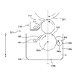
また、上記実施の形態においては、摺動ローラ540が、現像剤収容部530の側壁530aに接するように設けられ、回転することにより当該側壁530aに対し摺動することとしたが、図9に示すように、現像剤収容部530が、その内壁に突出部530cを有しており、摺動ローラ540は、現像剤Dを挟んで現像剤供給ローラ550に対向し、かつ、前記突出部530cに接するように設けられ、現像剤供給ローラ550の回転方向と同方向に回転することにより前記突出部530cに対し摺動することとしてもよい。
このようにすれば、摺動ローラ540の大きさを変えることなく、現像剤収容部530の現像剤収容スペースを広くすることができる。
Further, in the above embodiment, the sliding
In this way, the developer accommodating space of the
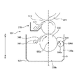
また、図10及び図11に示すように、現像剤収容部530が、その内壁にシール部材530dを有しており、摺動ローラ540は、現像剤Dを挟んで現像剤供給ローラ550に対向し、かつ、前記シール部材530dに接するように設けられ、現像剤供給ローラ550の回転方向と同方向に回転することにより前記シール部材530dに対し摺動することとしてもよい。
かかる場合には、気泡の通過を防ぐことに特化したシール部材530dが、摺動ローラ540と現像剤収容部530の内壁との間に位置することとなるから、摺動ローラ540と現像剤収容部530との間に到達した気泡が当該間を通過することが、より適切に防止される。
なお、当該シール部材530dとしては、フェルト製の部材(図10)や厚さ200μmのPET製のシート材(図11)等を用いることができる。また、シール部材530dは、現像剤収容部530の内壁に直接的に固定されていることとしてもよいし(図10)、現像剤収容部530の内壁に設けられた突出部530eに固定されていることとしてもよい(図11)。
Further, as shown in FIGS. 10 and 11, the
In such a case, since the
As the
また、上記実施の形態においては、現像剤供給ローラ550の表面に当接して、該現像剤供給ローラ550上の現像剤Dの量を規制するための規制ブレード560を有することとしたが、これに限定されるものではない。例えば、当該規制ブレード560を有しないこととしてもよいし、当該規制ブレード560が現像剤供給ローラ550の表面に当接しないこととしてもよい。
In the above embodiment, the
現像剤供給ローラ550の表面に当接して、該現像剤供給ローラ550上の現像剤Dの量を規制するための規制ブレード560を有する場合には、現像剤D内の気泡が、規制ブレード560と現像剤供給ローラ550との間に蓄積され易くなる。そして、このように気泡が蓄積されると、規制ブレード560が、現像剤供給ローラ550上の現像剤Dの量を適切に規制することができなくなる。そのため、かかる場合には、その量が不適切に規制された現像剤Dにより、感光体20Y、20M、20C、20Kに担持された潜像を現像して画像を形成することとなり、その画質に劣化が生ずることとなる。
したがって、前記規制ブレード560を有する場合には、上述した効果、すなわち、気泡が、摺動ローラ540と現像剤供給ローラ550の間及び摺動ローラ540と現像剤収容部530との間を通過すること、を防止し、得られる画像の画質が劣化しないようにするという効果、がより有効に発揮されることとなり、かかる点で、上記実施の形態の方がより効果的である。
When a
Therefore, when the
また、上記実施の形態において、前記現像剤Dは、常温で不揮発性を有する不揮発性液体現像剤であることとしたが、これに限定されるものではない。例えば、当該現像剤は、Isopar(商標:エクソン)をキャリアとした低濃度(1〜2wt%程度)かつ低粘度の常温で揮発性を有する揮発性液体現像剤であってもよい。 In the above-described embodiment, the developer D is a non-volatile liquid developer that is non-volatile at room temperature, but is not limited thereto. For example, the developer may be a low-concentration (about 1 to 2 wt%) and low-viscosity volatile liquid developer using Isopar (trademark: Exon) as a carrier at room temperature.
常温で不揮発性を有する不揮発性液体現像剤は、その不揮発性を発揮させるためにその粘度が高くなっている。高粘度の液体現像剤を上述した現像装置に使用した場合には、その粘度の高さに起因して、現像剤供給ローラ550が回転して現像剤Dに進入する際に空気が取り込まれ易くなるため、現像剤D内に気泡が発生し易くなる。また、粘度の高さに起因して、現像剤D内に発生した気泡が上方へ移動して現像剤Dの液面にて消滅する(すなわち、気泡が、液面上方の空気に戻る)現象、が発生しにくくなるため、現像剤D内に気泡が留まり易くなる。
したがって、上述した効果、すなわち、気泡を有する現像剤Dが現像ローラ510に供給されることを適切に防止し、得られる画像の画質が劣化しないようにするという効果、がより有効に発揮されることとなり、かかる点で、上記実施の形態の方がより効果的である。
The non-volatile liquid developer having non-volatility at normal temperature has a high viscosity in order to exhibit its non-volatility. When a high-viscosity liquid developer is used in the above-described developing device, air is easily taken in when the
Therefore, the above-described effect, that is, the effect of appropriately preventing the developer D having bubbles from being supplied to the developing
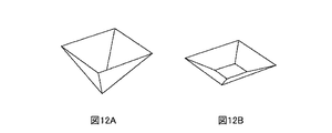
また、上記実施の形態においては、現像剤供給ローラ550に設けられた凹部として、溝550bを例に挙げて説明したが、例えば、図12Aや図12Bに示すような形状の穴部が現像剤供給ローラ550に多数設けられていることとしてもよい。なお、図12A及び図12Bは、現像剤供給ローラ550上に設けられる穴部の形状を示したものである。
In the above embodiment, the
また、上記実施の形態においては、現像剤Dを現像剤供給ローラ550へ供給する機能を有する部材は、一つのみ(摺動ローラ540)であったが、これに限定されるものではない。例えば、当該摺動ローラ540に加えて、現像剤Dを現像剤供給ローラ550へ供給する機能を有するローラを、前記鉛直面Aから見て現像剤供給ローラ550が回転して現像剤Dから進出する側に設けることとしてもよい。
In the above embodiment, the number of members having the function of supplying the developer D to the
===画像形成システム等の構成===
次に、本発明に係る実施の形態の一例である画像形成システムの実施形態について、図面を参照しながら説明する。
=== Configuration of Image Forming System etc. ===
Next, an image forming system according to an embodiment of the present invention will be described with reference to the drawings.
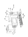
図13は、画像形成システムの外観構成を示した説明図である。画像形成システム700は、コンピュータ702と、表示装置704と、プリンタ706と、入力装置708と、読取装置710とを備えている。コンピュータ702は、本実施形態ではミニタワー型の筐体に収納されているが、これに限られるものではない。表示装置704は、CRT(Cathode Ray Tube:陰極線管)やプラズマディスプレイや液晶表示装置等が用いられるのが一般的であるが、これに限られるものではない。プリンタ706は、上記に説明されたプリンタが用いられている。入力装置708は、本実施形態ではキーボード708Aとマウス708Bが用いられているが、これに限られるものではない。読取装置710は、本実施形態ではフレキシブルディスクドライブ装置710AとCD−ROMドライブ装置710Bが用いられているが、これに限られるものではなく、例えばMO(Magneto Optical)ディスクドライブ装置やDVD(Digital Versatile Disk)等の他のものであっても良い。
FIG. 13 is an explanatory diagram showing an external configuration of the image forming system. The
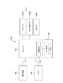
図14は、図13に示した画像形成システムの構成を示すブロック図である。コンピュータ702が収納された筐体内にRAM等の内部メモリ802と、ハードディスクドライブユニット804等の外部メモリがさらに設けられている。
FIG. 14 is a block diagram showing a configuration of the image forming system shown in FIG. An
なお、以上の説明においては、プリンタ706が、コンピュータ702、表示装置704、入力装置708、及び、読取装置710と接続されて画像形成システムを構成した例について説明したが、これに限られるものではない。例えば、画像形成システムが、コンピュータ702とプリンタ706から構成されても良く、画像形成システムが表示装置704、入力装置708及び読取装置710のいずれかを備えていなくても良い。
In the above description, the example in which the
また、例えば、プリンタ706が、コンピュータ702、表示装置704、入力装置708、及び、読取装置710のそれぞれの機能又は機構の一部を持っていても良い。一例として、プリンタ706が、画像処理を行う画像処理部、各種の表示を行う表示部、及び、デジタルカメラ等により撮影された画像データを記録した記録メディアを着脱するための記録メディア着脱部等を有する構成としても良い。
For example, the
このようにして実現された画像形成システムは、システム全体として従来システムよりも優れたシステムとなる。 The image forming system realized in this way is a system superior to the conventional system as a whole system.
10 レーザビームプリンタ
15Y、15M、15C、15K 現像部
20Y、20M、20C、20K 感光体
30Y、30M、30C、30K 帯電ユニット
40Y、40M、40C、40K 露光ユニット
50Y、50M、50C、50K 現像ユニット
60Y、60M、60C、60K 一次転写ユニット
70 中間転写体
73Y、73M、73C、73K 除電ユニット
75Y、75M、75C、75K 感光体クリーニングユニット
76Y、76M、76C、76K 感光体クリーニングブレード
80 二次転写ユニット
100 制御ユニット 101 メインコントローラ
102 ユニットコントローラ 112 インターフェイス
113 画像メモリ 510 現像ローラ
530 現像剤収容部 530a 側壁
530b 底部 530c 突出部
530d シール部材 530e 突出部
540 摺動ローラ 540a 中心軸
550 現像剤供給ローラ
550a 中心軸 550b 溝
560 規制ブレード 560a エッジ部
562 規制ブレード支持部材
570 現像ローラクリーニングユニット
571 現像ローラクリーニングブレード
700 画像形成システム 702 コンピュータ
704 表示装置 706 プリンタ
708 入力装置 708A キーボード
708B マウス 710 読取装置
710A フレキシブルディスクドライブ装置
710B CD−ROMドライブ装置
802 内部メモリ
804 ハードディスクドライブユニット
D 現像剤
10
Claims (13)
液体現像剤を前記現像剤担持体に供給するための回転可能な現像剤供給部材と、
液体現像剤を収容するための現像剤収容体と、を有し、
前記現像剤担持体に担持された液体現像剤によって、像担持体に担持された潜像を現像する現像装置であって、
前記現像剤供給部材が、その一部が露出した状態で、前記現像剤収容体に収容された液体現像剤に浸っている現像装置において、
前記現像剤供給部材に対向し、かつ、前記現像剤収容体に接するように設けられ、前記現像剤供給部材の回転方向と同方向に回転することにより前記現像剤収容体に対し摺動する摺動ローラを有することを特徴とする現像装置。 A developer carrier for carrying a liquid developer;
A rotatable developer supply member for supplying a liquid developer to the developer carrier;
A developer container for containing a liquid developer,
A developing device for developing a latent image carried on an image carrier by a liquid developer carried on the developer carrier,
In the developing device in which the developer supply member is immersed in the liquid developer housed in the developer container with a part thereof exposed,
A slide that faces the developer supply member and is in contact with the developer container, and slides relative to the developer container by rotating in the same direction as the rotation direction of the developer supply member. A developing device having a moving roller.
前記現像剤供給部材は、現像剤供給ローラであることを特徴とする現像装置。 The developing device according to claim 1,
The developing device, wherein the developer supplying member is a developer supplying roller.
前記摺動ローラは、液体現像剤の液中に設けられており、液体現像剤を挟んで前記現像剤供給ローラに対向することを特徴とする現像装置。 The developing device according to claim 2,
The developing device, wherein the sliding roller is provided in a liquid developer and faces the developer supply roller with the liquid developer interposed therebetween.
前記摺動ローラは、その中心軸の軸方向が前記現像剤供給ローラの中心軸の軸方向に沿うように設けられ、該摺動ローラの中心軸は該現像剤供給ローラの中心軸よりも鉛直方向下方に位置することを特徴とする現像装置。 The developing device according to claim 3,
The sliding roller is provided such that the axial direction of the central axis thereof is along the axial direction of the central axis of the developer supply roller, and the central axis of the sliding roller is perpendicular to the central axis of the developer supply roller. A developing device, which is located below the direction.
前記摺動ローラは、前記現像剤供給ローラの中心軸を通る鉛直面から見て、前記現像剤供給ローラが回転して液体現像剤に進入する側に設けられていることを特徴とする現像装置。 The developing device according to claim 4,
The developing device, wherein the sliding roller is provided on a side where the developer supply roller rotates and enters the liquid developer as viewed from a vertical plane passing through a central axis of the developer supply roller. .
前記摺動ローラが回転している状態で、前記現像剤供給ローラの回転が開始することを特徴とする現像装置。 The developing device according to any one of claims 3 to 5,
The developing device, wherein the developer supply roller starts to rotate while the sliding roller is rotating.
前記現像剤収容体は、その内壁に突出部を有し、
前記摺動ローラは、液体現像剤を挟んで前記現像剤供給ローラに対向し、かつ、前記突出部に接するように設けられ、前記現像剤供給ローラの回転方向と同方向に回転することにより前記突出部に対し摺動することを特徴とする現像装置。 The developing device according to any one of claims 3 to 6,
The developer container has a protrusion on its inner wall,
The sliding roller is provided so as to face the developer supply roller with the liquid developer interposed therebetween and to be in contact with the protrusion, and rotates in the same direction as the rotation direction of the developer supply roller. A developing device that slides relative to a protruding portion.
前記現像剤収容体は、その内壁にシール部材を有し、
前記摺動ローラは、液体現像剤を挟んで前記現像剤供給ローラに対向し、かつ、前記シール部材に接するように設けられ、前記現像剤供給ローラの回転方向と同方向に回転することにより前記シール部材に対し摺動することを特徴とする現像装置。 The developing device according to any one of claims 3 to 6,
The developer container has a seal member on its inner wall,
The sliding roller is provided so as to face the developer supply roller with the liquid developer interposed therebetween and to be in contact with the seal member, and rotates in the same direction as the rotation direction of the developer supply roller. A developing device that slides on a seal member.
前記現像剤供給ローラの表面に当接して、該現像剤供給ローラ上の液体現像剤の量を規制するための規制部材を有することを特徴とする現像装置。 The developing device according to any one of claims 3 to 8,
A developing device comprising: a regulating member that abuts on a surface of the developer supply roller and regulates an amount of the liquid developer on the developer supply roller.
前記液体現像剤は、常温で不揮発性を有する不揮発性液体現像剤であることを特徴とする現像装置。 The developing device according to any one of claims 1 to 9,
The developing device according to claim 1, wherein the liquid developer is a non-volatile liquid developer that is non-volatile at room temperature.
液体現像剤を前記現像剤担持体に供給するための回転可能な現像剤供給部材と、
液体現像剤を収容するための現像剤収容体と、を有し、
前記現像剤担持体に担持された液体現像剤によって、像担持体に担持された潜像を現像する現像装置であって、
前記現像剤供給部材が、その一部が露出した状態で、前記現像剤収容体に収容された液体現像剤に浸っている現像装置において、
前記現像剤供給部材に対向し、かつ、前記現像剤収容体に接するように設けられ、前記現像剤供給部材の回転方向と同方向に回転することにより前記現像剤収容体に対し摺動する摺動ローラを有し、
前記現像剤供給部材は、現像剤供給ローラであり、
前記摺動ローラは、液体現像剤の液中に設けられており、液体現像剤を挟んで前記現像剤供給ローラに対向し、
前記摺動ローラは、その中心軸の軸方向が前記現像剤供給ローラの中心軸の軸方向に沿うように設けられ、該摺動ローラの中心軸は該現像剤供給ローラの中心軸よりも鉛直方向下方に位置し、
前記摺動ローラは、前記現像剤供給ローラの中心軸を通る鉛直面から見て、前記現像剤供給ローラが回転して液体現像剤に進入する側に設けられており、
前記摺動ローラが回転している状態で、前記現像剤供給ローラの回転が開始し、
前記現像剤供給ローラの表面に当接して、該現像剤供給ローラ上の液体現像剤の量を規制するための規制部材を有し、
前記液体現像剤は、常温で不揮発性を有する不揮発性液体現像剤であることを特徴とする現像装置。 A developer carrier for carrying a liquid developer;
A rotatable developer supply member for supplying a liquid developer to the developer carrier;
A developer container for containing a liquid developer,
A developing device for developing a latent image carried on an image carrier by a liquid developer carried on the developer carrier,
In the developing device in which the developer supply member is immersed in the liquid developer housed in the developer container with a part thereof exposed,
A slide that faces the developer supply member and is in contact with the developer container, and slides relative to the developer container by rotating in the same direction as the rotation direction of the developer supply member. A moving roller,
The developer supply member is a developer supply roller,
The sliding roller is provided in the liquid developer, and faces the developer supply roller with the liquid developer interposed therebetween.
The sliding roller is provided such that the axial direction of the central axis thereof is along the axial direction of the central axis of the developer supply roller, and the central axis of the sliding roller is perpendicular to the central axis of the developer supply roller. Located in the lower direction,
The sliding roller is provided on the side where the developer supply roller rotates and enters the liquid developer when viewed from a vertical plane passing through the central axis of the developer supply roller,
With the sliding roller rotating, the developer supply roller starts to rotate,
A regulating member for contacting the surface of the developer supply roller to regulate the amount of liquid developer on the developer supply roller;
The developing device according to claim 1, wherein the liquid developer is a non-volatile liquid developer that is non-volatile at room temperature.
液体現像剤を担持するための現像剤担持体と、液体現像剤を前記現像剤担持体に供給するための回転可能な現像剤供給部材と、液体現像剤を収容するための現像剤収容体と、を有し、前記現像剤担持体に担持された液体現像剤によって、前記像担持体に担持された潜像を現像する現像装置であって、前記現像剤供給部材が、その一部が露出した状態で、前記現像剤収容体に収容された液体現像剤に浸っている現像装置と、
を備えた画像形成装置において、
前記現像剤供給部材に対向し、かつ、前記現像剤収容体に接するように設けられ、前記現像剤供給部材の回転方向と同方向に回転することにより前記現像剤収容体に対し摺動する摺動ローラを有することを特徴とする画像形成装置。 An image carrier for carrying a latent image;
A developer carrying member for carrying the liquid developer, a rotatable developer supply member for feeding the liquid developer to the developer carrying member, and a developer containing member for containing the liquid developer; And a developing device for developing the latent image carried on the image carrier by the liquid developer carried on the developer carrier, wherein the developer supply member is partially exposed. A developing device immersed in a liquid developer stored in the developer container,
In an image forming apparatus comprising:
A slide that faces the developer supply member and is in contact with the developer container, and slides relative to the developer container by rotating in the same direction as the rotation direction of the developer supply member. An image forming apparatus having a moving roller.
このコンピュータに接続可能な画像形成装置であって、潜像を担持するための像担持体と、液体現像剤を担持するための現像剤担持体と、液体現像剤を前記現像剤担持体に供給するための回転可能な現像剤供給部材と、液体現像剤を収容するための現像剤収容体と、を有し、前記現像剤担持体に担持された液体現像剤によって、前記像担持体に担持された潜像を現像する現像装置であって、前記現像剤供給部材が、その一部が露出した状態で、前記現像剤収容体に収容された液体現像剤に浸っている現像装置と、を備えた画像形成装置、
を有する画像形成システムにおいて、
前記現像剤供給部材に対向し、かつ、前記現像剤収容体に接するように設けられ、前記現像剤供給部材の回転方向と同方向に回転することにより前記現像剤収容体に対し摺動する摺動ローラを有することを特徴とする画像形成システム。 Computer and
An image forming apparatus connectable to the computer, comprising: an image carrier for carrying a latent image; a developer carrier for carrying a liquid developer; and supplying a liquid developer to the developer carrier. A developer supply member capable of rotating, and a developer container for containing the liquid developer, and is carried on the image carrier by the liquid developer carried on the developer carrier. A developing device for developing the latent image, wherein the developer supplying member is immersed in a liquid developer contained in the developer containing body with a part thereof exposed. Provided image forming apparatus,
In an image forming system having
A slide that faces the developer supply member and is in contact with the developer container, and slides relative to the developer container by rotating in the same direction as the rotation direction of the developer supply member. An image forming system comprising a moving roller.
Priority Applications (1)
| Application Number | Priority Date | Filing Date | Title |
|---|---|---|---|
| JP2004110086A JP2005292638A (en) | 2004-04-02 | 2004-04-02 | Developing device, image forming apparatus, and image forming system |
Applications Claiming Priority (1)
| Application Number | Priority Date | Filing Date | Title |
|---|---|---|---|
| JP2004110086A JP2005292638A (en) | 2004-04-02 | 2004-04-02 | Developing device, image forming apparatus, and image forming system |
Publications (1)
| Publication Number | Publication Date |
|---|---|
| JP2005292638A true JP2005292638A (en) | 2005-10-20 |
Family
ID=35325600
Family Applications (1)
| Application Number | Title | Priority Date | Filing Date |
|---|---|---|---|
| JP2004110086A Pending JP2005292638A (en) | 2004-04-02 | 2004-04-02 | Developing device, image forming apparatus, and image forming system |
Country Status (1)
| Country | Link |
|---|---|
| JP (1) | JP2005292638A (en) |
-
2004
- 2004-04-02 JP JP2004110086A patent/JP2005292638A/en active Pending
Similar Documents
| Publication | Publication Date | Title |
|---|---|---|
| JP4507683B2 (en) | Liquid development equipment | |
| JP4461884B2 (en) | Developing device, image forming apparatus, and image forming system | |
| JP4363121B2 (en) | Liquid developing device, image forming apparatus, and image forming system | |
| JP4432415B2 (en) | Liquid developing device, image forming apparatus, and image forming system | |
| JP4635556B2 (en) | Developing device, image forming apparatus, and image forming system | |
| JP4513401B2 (en) | Developing device and image forming apparatus | |
| JP4363135B2 (en) | Liquid developing device, image forming apparatus, and image forming system | |
| JP4572563B2 (en) | Developing device, image forming apparatus, and image forming system | |
| JP4461883B2 (en) | Liquid developing device, image forming apparatus, and image forming system | |
| JP2005292638A (en) | Developing device, image forming apparatus, and image forming system | |
| JP4419473B2 (en) | Image forming apparatus, image forming system, and image forming method | |
| JP4289077B2 (en) | Image forming apparatus, image forming system, and image forming method | |
| JP4453405B2 (en) | Developing device, image forming apparatus, and image forming system | |
| JP4581623B2 (en) | Liquid developing device, image forming apparatus, image forming system, and developer supply roller | |
| JP4609033B2 (en) | Developing device, image forming apparatus, and image forming system | |
| JP4479187B2 (en) | Developing device and image forming apparatus | |
| JP2005316114A (en) | Developing device, image forming apparatus, and image forming system | |
| JP4858640B2 (en) | Developing device and image forming apparatus | |
| JP4635565B2 (en) | Liquid developing device and image forming apparatus | |
| US20050063736A1 (en) | Liquid development device, image forming apparatus, and image forming system | |
| JP4363122B2 (en) | Liquid developing device, image forming apparatus, and image forming system | |
| JP2005292636A (en) | Developing device, image forming apparatus, and image forming system | |
| JP2005070184A (en) | Developing device, regulating member, image forming apparatus, and image forming system | |
| JP4599949B2 (en) | Developing device and image forming apparatus | |
| JP2006030639A (en) | Developing device, developer supply roller, image forming apparatus, and image forming system |