JP4635358B2 - Method for manufacturing partial reflectance modulation pattern forming body - Google Patents
Method for manufacturing partial reflectance modulation pattern forming body Download PDFInfo
- Publication number
- JP4635358B2 JP4635358B2 JP2001080460A JP2001080460A JP4635358B2 JP 4635358 B2 JP4635358 B2 JP 4635358B2 JP 2001080460 A JP2001080460 A JP 2001080460A JP 2001080460 A JP2001080460 A JP 2001080460A JP 4635358 B2 JP4635358 B2 JP 4635358B2
- Authority
- JP
- Japan
- Prior art keywords
- photosensitive resin
- resin composition
- modulation pattern
- refractive index
- partial reflectance
- Prior art date
- Legal status (The legal status is an assumption and is not a legal conclusion. Google has not performed a legal analysis and makes no representation as to the accuracy of the status listed.)
- Expired - Fee Related
Links
Images
Landscapes
- Credit Cards Or The Like (AREA)
- Optical Elements Other Than Lenses (AREA)
- Photosensitive Polymer And Photoresist Processing (AREA)
- Optical Filters (AREA)
- Materials For Photolithography (AREA)
Description
【0001】
【発明の属する技術分野】
本発明は、感光性樹脂組成物の硬化部と未硬化部の耐熱軟化性の差を利用した新規な反射率変調画像の形成方法に関するものであり、有価証券、クレジットカード等の偽造防止に利用することができる。また、本発明による反射率変調画像形成法は上述のような製品を製造するに当たって、小ロット単位の製品に於いても、より効率的に製造でき、しかも新たなデサインの開発を可能とするパターン形成方法に関する。
【0002】
【従来の技術】
従来、有価証券類等の印刷物への偽造防止性付与方法としては、すかしによる絵柄または文字、複雑な彫刻模様等が一般的であるが、このような偽造防止手段は熟練した技能と時間が必要である上、手間と時間を費やして作られたパターンが使用できる対象となる製品は一つに限られる。そのため目的や製品が異なる度に同じ工程を繰り返す為、手間と時間が多量に必要とされる。
【0003】
また、クレジットカード、抽選券等の大量発行に伴い、種々の偽造防止手段が考案されている。例えば、レリーフホログラム、オパールエンボス柄、赤外線の反射及び吸収、放電破壊記録、磁気記録等の技術はクレジットカードを中心に利用されている。特にレリーフホログラムに代表されるような複雑で微細なパターンを作製するには、高度な撮影技術と設備が必要である為、偽造複製が困難となる。
【0004】
【発明が解決しようとする課題】
本発明が解決しようとする課題は、上述のごとく従来の偽造防止技術で必要とされる熟練した技能や多量の時間、高価な設備と高度な撮影技術等に頼らなくとも完全に近い偽造防止方法を実現することである。さらに、小ロット製品を生産する場合に於いては、より安価な製造方法を実現することを目的とするものである。
【0005】
請求項1に係る発明においては、以下の工程を有することを特徴とする部分反射率変調パターン形成体の製造方法を提供するものである。
(a)支持体上に屈折率の異なる感光性樹脂組成物を積層する工程。
(b)前記感光性樹脂組成物積層体の表面に部分露光を施すことにより、前記感光性樹脂組成物積層体に光硬化潜像パターンを形成する工程。
(c)前記光硬化潜像パターンが形成された感光性樹脂組成物積層体を所定の温度で加熱処理して、潜像を反射光強度の変調パターンとして可視化する工程。
(d)反射光強度の変調パターンが形成された前記感光性樹脂組成物積層体に所定の露光量で全面露光を施すことにより、可視化された反射光強度の変調パターンを定着する工程。
請求項2に係る発明においては、屈折率の異なる感光性樹脂組成物を少なくとも2種以上積層してなることを特徴とする請求項1記載の部分反射率変調パターン形成体の製造方法を提供するものである。
請求項3に係る発明においては、屈折率の異なる感光性樹脂組成物の屈折率差は互いに0.02以上であることを特徴とする請求項1または2記載の部分反射率変調パターン形成体の製造方法を提供するものである。
請求項4に係る発明においては、感光性樹脂組成物積層体の各々の感光性樹脂組成物膜厚は光学膜厚nd(屈折率n×形状膜厚dの積)として、検出中心感度波長λの1/4もしくは1/4と1/2の組み合わせからなることを特徴とする請求項1または2または3記載の部分反射率変調パターン形成体の製造方法を提供するものである。
【0006】
ここで、屈折率の異なる感光性樹脂組成物は、パターン形成後のパターン形成部では少なくとも2種以上積層してなることを特徴とする感光性樹脂組成物積層体であり、この屈折率の異なる感光性樹脂組成物の屈折率差は好ましくは互いに0.02以上である。
【0007】
さらに、感光性樹脂組成物積層体の各々の感光性樹脂組成物膜厚は光学膜厚nd(屈折率n×形状膜厚dの積)として、検出中心感度波長λの1/4もしくは1/4と1/2の組み合わせからなる積層体とすることにより、同一面内において、好適な部分的に反射率が変調されたパターンとする事ができる。
【0008】
【発明の実施の形態】
以下、まず本発明の構成材料について説明し、次に製造工程を図面を用いて詳細に説明する。
【0009】
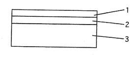
図1に特に限定されるものではないが、光学薄膜として低反射機能が付与できる膜の層構成を示した。まず、図2に示す様に、形成体上に2層膜を形成する。この膜1、2は室温では固体状態の感光性樹脂組成物層であり、光硬化性樹脂もしくはオリゴマー、モノマー等を少なくとも一成分とし、さらに光重合開始剤を添加した熱可塑性樹脂組成物から成る。1は相対的に低屈折率領域、2には高屈折率領域の性能を付与する。3は支持体であり、プレート、シート若しくはフィルム等であるが、これらに限らず3次元形状でも良い。
【0010】
本発明に述べる光硬化性で且つ室温では固体状態の熱可塑性樹脂組成物層1としては、一般的な熱可塑性樹脂と少なくとも2官能以上で良好な架橋反応を行うアクリレート若しくはメタクリレートとの混合物に光重合開始剤を少量添加したものが使用できる。具体的には、熱可塑性樹脂としてアクリル樹脂、スチレン−アクリル共重合樹脂、ポリエステル樹脂、ポリビニルブチラール、ポリカーボネート樹脂、塩ビ−酢ビ共重合樹脂、スチレン樹脂、塩化ビニル樹脂、アクリロニトリル−スチレン共重合樹脂、熱可塑性ポリウレタン樹脂等が使用できる。また、アクリレート若しくはメタクリレート単独でも室温では固体状態を呈する熱可塑性樹脂であれば使用することができる。例えば、種々のウレタンアクリレート及びメタクリレートオリゴマー、分子内にイソシアヌレート環構造を有する種々のアクリレート及びメタクリレート、分子内にビスフェノールA、ビスフェノールS等の構造を有するエポキシアクリレート及びメタクリレート、ポリブタジエンウレタンメタクリレート、ポリスチリルエチルメタクリレート等が挙げられ、さらに水性UV硬化型樹脂も使用することができる。
【0011】
この感光性樹脂組成物に対し、相対的に低屈折率の性能を付与するには、分子構造内にフッ素原子を含有するポリマーやオリゴマー、モノマー類、MgF2、SiO2等の低屈折率無機微粒子を配合することが効果的である。また、高屈折率の性能を付与するには、分子構造内にフッ素原子以外のハロゲン原子を含有するポリマーやオリゴマー、モノマー類、TiO2、ZnO、SnO2等の高屈折率無機微粒子を屈折率調整用として配合することが好ましい。
【0012】
また光重合開始剤としては使用する光の波長に吸収を有する化合物であれば任意に使用でき、特に限定するものではない。例えば、ベンゾイン、ベンジルケタール、アセトフェノン等の誘導体に代表される自己開裂型の化合物及びベンゾフェノン、芳香族ケトン、ミヒラーズケトン等の分子構造を有する種々の水素引き抜き型の光重合開始剤を配合することが好ましく、さらに必要に応じて種々の増感剤との併用も可能である。
【0013】
次に製造工程について説明する。
【0014】
図2に於いて、支持体3上に低屈折率の感光性樹脂組成物層2を設け、さらにその表面に感光性樹脂組成物層1設ける方法として、ロールコート、バーコート等、公知の塗布方法によって作製することができる。一方、部分的に上記感光性樹脂組成物層を形成する場合には、グラビアコーティング等の一般的な印刷技術を応用する方法、あるいは転写技術を利用することもできる。
【0015】
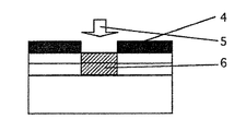
次に図3に示すごとく、感光性樹脂組成物層1上にフォトマスク4を密着させ、露光5することにより、感光性樹脂組成物層1、2の層内に部分的に硬化した潜像領域6を形成する。
【0016】
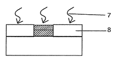
次いで図4に示すように、感光性樹脂組成物層1、2に熱7を加えることによって、軟化、溶融させ、感光性樹脂組成物層1、2の境界面を消失させることで光の干渉効果を変化させ、露光部6と未露光部8の間に反射率のコントラストに基ずくパターンを可視化する。
【0017】
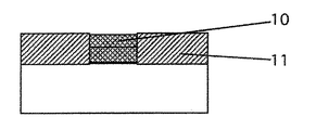
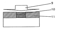
さらに、図5には、露光部6と未露光部8に前面露光9を加えることによって、感光性樹脂組成物層全体を硬化させることで、可視化したパターンを定着する工程を示したものである。
【0018】
(作用)
以上のように、本発明においては、光学薄膜として2層構成の感光性樹脂組成物薄膜を代表例とし、図1の構成で低、高屈折率層の光学膜厚nd(屈折率n×形状膜厚dの積)をそれぞれλ/4とすれば、低反射機能を有する膜となる。そこで、図4に示すように、感光性樹脂組成物層1、2の境界面を消失させると1層構成のλ/2膜に変化させることができ、反射強調膜として機能させることができる。従って、露光部6は低反射領域、未露光部8は反射強調領域としてパターンを形成することができる。
【0019】
【実施例】
次に、本発明を実施例により具体的に説明する。
<実施例1>
以下に実施例および比較例を挙げて本発明について具体的に説明するが、本発明はこれらの実施例に限定されるものではない。尚、部は特に断りのない限り重量基準である。
【0020】
高屈折率感光性樹脂組成物
下記組成の光硬化性オリゴマーを含有する熱可塑性樹脂組成物を高屈折率感光性樹脂組成物とした。各成分の屈折率の加成性から見積もることができる屈折率を約1.76とした。
飽和共重合ポリエステル樹脂(ユニチカ社製、エリーテルUE−3201)−1部
アクリル樹脂(三菱レイヨン社製、ダイヤナールBR−77)−3部
ペンタエリスリトールヘキサアクリレート−2.5部
酸化チタンゾル(平均粒子径約40nm)−3.5部
光重合開始剤(チバガイギー社製、イルガキュアー651)−1重量部
【0021】
低屈折率感光性樹脂組成物
下記組成の光硬化性オリゴマーを含有する熱可塑性樹脂組成物を低屈折率感光性樹脂組成物とした。各成分の屈折率の加成性から見積もることができる屈折率を約1.49とした。
アクリル樹脂(三菱レイヨン社製、ダイヤナールBR−77)−4部
ペンタエリスリトールヘキサアクリレート−2.5部
コロイダルシリカ(平均粒子径約30nm)−3.5部
光重合開始剤(チバガイギー社製、イルガキュアー651)−1重量部
【0022】
低反射薄膜層の形成
上記、高屈折率感光性樹脂組成物を酢酸エチルにて、固形分が4wt%となるように希釈した後、厚み120μmのポリエステルフィルム上にバーコーターによって塗布し、80℃,1minの熱乾燥を施すことで成膜した。さらに、低屈折率感光性樹脂組成物をその下地である高屈折率感光性樹脂組成物の薄膜層を溶解しないように、エタノールを溶媒として使用し、前記、高屈折率感光性樹脂組成物の塗布・乾燥条件と同一条件にて積層、成膜した。光学膜厚(nd=屈折率n×形状膜厚d(nm))が高、低それぞれnd=550/4nmとなるように低反射薄膜層を形成した。波長500nmでの反射率は約0.8%であった。
【0023】
部分反射率変調パターンの製造
上記の方法で得られた高/低屈折率感光性樹脂組成物から成る低反射薄膜層の表面に、フォトマスクを密着させた後、高圧水銀ランプ(出力:120W/cm)による紫外線を積算露光量として、500mJ/cm2照射することによって、低反射薄膜層内に部分的な硬化領域を形成させた。次に、これを100℃,5minの条件にて加熱することにより、未露光部の高/低屈折率感光性樹脂組成物間の境界面を消失させた。その結果、未露光部の波長500nmでの反射率は約4.1%であり、硬化部と未硬化部のコントラストは鮮明に可視化した。次に、高/低屈折率感光性樹脂組成物薄膜層全体に、上記と同一条件の紫外線の全面露光を施すことによって、可視化した部分反射率変調パターンを定着した。
【0024】
【実施例2】
実施例1で作製した高/低屈折率感光性樹脂組成物から成る低反射薄膜層の表面に、実施例1で使用したフォトマスクの代わりに、人物の顔が撮影された白黒ポジ画像の透過フィルム原稿を密着させ、実施例1と同一の方法、条件にて部分反射率変調画像を作製した。反射率コントラストが鮮明で、明るい人物画像を得た。
【0025】
【発明の効果】
上述の実施例の説明からも明らかなように、本発明は多層光学薄膜層間の界面を保持する部分と消失させる部分を光硬化と熱軟化変形を組み合わせることで、部分的に反射率が変調されたパターンを製造することを特徴とする。従って、感光性樹脂へのパターン露光による潜像形成、及びその熱現像による潜像の可視化、さらに可視化された像の光定着を利用する原理的に単純で簡便な乾式プロセスであるため、熟練した技能や多量の時間、高価な設備と高度な撮影技術等に頼らなくとも完全に近い偽造防止方法を実現することができる。さらに、小ロット製品を生産する場合に於いては、より安価な製造方法となる。また部分反射率変調パターンを得るための画像は露光プロセスで決定するため、異なる絵柄の多重露光等の方法を用いて、新規な意匠性を有する部分反射率変調パターンの開発が容易になる。そのため、さらに高度な偽造防止効果を付与する手段として有効である。
【図面の簡単な説明】
【図1】部分反射率変調パターン形成体の概念断面図。
【図2】部分反射率変調パターン形成体の製造方法中、屈折率の異なる感光性樹脂組成物積層状態の概念断面図。
【図3】部分反射率変調パターン形成体の製造方法中、感光性樹脂組成物積層体に光硬化潜像パターンを形成する工程の説明図。
【図4】部分反射率変調パターン形成体の製造方法中、光硬化潜像パターンが形成された感光性樹脂組成物積層体を加熱処理することで、潜像を反射光強度の変調パターンとして可視化する工程の説明図。
【図5】部分反射率変調パターン形成体の製造方法中、感光性樹脂組成物積層体に全面露
【符号の説明】
1 低屈折率感光性樹脂組成物層
2 高屈折率感光性樹脂組成物層
3 支持体
4 フォトマスク
5 光
6 感光性樹脂組成物積層体層の硬化潜像
7 熱
8 高反射率領域に変化した未露光部
9 全面露光のための光
10 光硬化定着後の低反射率領域
11 光硬化定着後の高反射率領域[0001]
BACKGROUND OF THE INVENTION
The present invention relates to a novel method for forming a reflectance-modulated image using the difference in heat-softening property between a cured part and an uncured part of a photosensitive resin composition, and is used for preventing counterfeiting of securities, credit cards, etc. can do. In addition, the reflectance modulation image forming method according to the present invention is a pattern which can be manufactured more efficiently even in a small lot unit product and a new design can be developed. It relates to a forming method.
[0002]
[Prior art]
Conventionally, as a method for imparting anti-counterfeiting property to printed matter such as securities, a pattern or character using a watermark, a complicated engraving pattern, etc. are generally used. In addition to this, there is only one product that can be used with patterns that are time-consuming and time-consuming. Therefore, since the same process is repeated every time the purpose and product are different, a lot of labor and time are required.
[0003]
In addition, various forgery prevention means have been devised along with the large-scale issuance of credit cards, lottery tickets, and the like. For example, techniques such as relief holograms, opal embossed patterns, infrared reflection and absorption, discharge destruction recording, and magnetic recording are used mainly for credit cards. In particular, in order to produce a complicated and fine pattern as represented by a relief hologram, advanced photographing techniques and equipment are required, so that forgery reproduction becomes difficult.
[0004]
[Problems to be solved by the invention]
The problem to be solved by the present invention is, as described above, a technique for preventing counterfeiting that is almost complete without relying on skilled skills, a large amount of time, expensive equipment, advanced photographing techniques, and the like that are required for conventional forgery prevention techniques. Is to realize. Furthermore, when producing a small lot product, it aims at realizing a cheaper manufacturing method.
[0005]
In the invention according to 請 Motomeko 1, there is provided a method for manufacturing a partial reflectance modulation pattern formed body characterized by having the following steps.
(A) The process of laminating | stacking the photosensitive resin composition from which a refractive index differs on a support body.
(B) The process of forming a photocurable latent image pattern in the said photosensitive resin composition laminated body by performing partial exposure to the surface of the said photosensitive resin composition laminated body.
(C) A step of visualizing the latent image as a reflected light intensity modulation pattern by heat-treating the photosensitive resin composition laminate on which the photocured latent image pattern is formed at a predetermined temperature.
(D) A step of fixing the visualized modulation pattern of the reflected light intensity by subjecting the photosensitive resin composition laminate on which the modulation pattern of the reflected light intensity has been formed to entire surface exposure with a predetermined exposure amount.
In the invention according to
In the invention which concerns on Claim 3 , the refractive index difference of the photosensitive resin composition from which refractive index differs is 0.02 or more mutually, The partial reflectance modulation | alteration pattern formation body of
In the invention according to claim 4 , each photosensitive resin composition film thickness of the photosensitive resin composition laminate is an optical film thickness nd (product of refractive index n × shape film thickness d), and a detection center sensitivity wavelength λ. 4. The method for producing a partial reflectance modulation pattern forming body according to
[0006]
Here, the photosensitive resin composition having a different refractive index is a photosensitive resin composition laminate in which at least two or more kinds are laminated in the pattern forming portion after pattern formation, and this refractive index is different. The refractive index difference of the photosensitive resin composition is preferably 0.02 or more.
[0007]
Further, each photosensitive resin composition film thickness of the photosensitive resin composition laminate is an optical film thickness nd (product of refractive index n × shape film thickness d), which is 1/4 or 1/1 of the detection center sensitivity wavelength λ. By using a laminate composed of a combination of 4 and 1/2, it is possible to obtain a pattern in which the reflectance is partially modulated in the same plane.
[0008]
DETAILED DESCRIPTION OF THE INVENTION
Hereinafter, the constituent materials of the present invention will be described first, and then the manufacturing process will be described in detail with reference to the drawings.
[0009]
Although not specifically limited to FIG. 1, the layer structure of the film | membrane which can provide a low reflection function as an optical thin film was shown. First, as shown in FIG. 2, a two-layer film is formed on the formed body. These
[0010]
The thermoplastic
[0011]
In order to impart relatively low refractive index performance to this photosensitive resin composition, polymers and oligomers containing fluorine atoms in the molecular structure, monomers, low refractive index inorganics such as MgF 2 and SiO 2 It is effective to blend fine particles. In addition, in order to provide high refractive index performance, polymers or oligomers containing monomers other than fluorine atoms in the molecular structure, monomers, high refractive index inorganic fine particles such as TiO 2 , ZnO, SnO 2 are used as refractive indexes. It is preferable to mix for adjustment.
[0012]
The photopolymerization initiator is not particularly limited as long as it is a compound having absorption at the wavelength of light to be used. For example, it is preferable to blend a self-cleavable compound typified by derivatives such as benzoin, benzyl ketal and acetophenone and various hydrogen abstraction type photopolymerization initiators having molecular structures such as benzophenone, aromatic ketone and Michler's ketone. Furthermore, it can be used in combination with various sensitizers as necessary.
[0013]
Next, the manufacturing process will be described.
[0014]
In FIG. 2, as a method for providing a photosensitive
[0015]
Next, as shown in FIG. 3, a latent image partially cured in the layers of the photosensitive
[0016]
Next, as shown in FIG. 4,
[0017]
Further, FIG. 5 shows a process of fixing the visualized pattern by curing the entire photosensitive resin composition layer by adding a
[0018]
(Function)
As described above, in the present invention, a photosensitive resin composition thin film having a two-layer structure is used as a representative example as an optical thin film. If the product of the film thickness d is λ / 4, the film has a low reflection function. Therefore, as shown in FIG. 4, when the boundary surface between the photosensitive
[0019]
【Example】
Next, the present invention will be specifically described with reference to examples.
<Example 1>
EXAMPLES The present invention will be specifically described below with reference to examples and comparative examples, but the present invention is not limited to these examples. The parts are based on weight unless otherwise specified.
[0020]
High refractive index photosensitive resin composition A thermoplastic resin composition containing a photocurable oligomer having the following composition was used as a high refractive index photosensitive resin composition. The refractive index that can be estimated from the additivity of the refractive index of each component was about 1.76.
Saturated copolyester resin (Unitika, Elitel UE-3201)-1 part acrylic resin (Mitsubishi Rayon, Dianar BR-77)-3 parts pentaerythritol hexaacrylate-2.5 parts titanium oxide sol (average particle size About 40 nm) -3.5 parts photopolymerization initiator (manufactured by Ciba Geigy, Irgacure 651) -1 part by weight
Low Refractive Index Photosensitive Resin Composition A thermoplastic resin composition containing a photocurable oligomer having the following composition was defined as a low refractive index photosensitive resin composition. The refractive index that can be estimated from the additivity of the refractive index of each component was about 1.49.
Acrylic resin (Mitsubishi Rayon Co., Ltd., Dianar BR-77)-4 parts pentaerythritol hexaacrylate-2.5 parts colloidal silica (average particle size about 30 nm)-3.5 parts Photopolymerization initiator (Ciba Geigy, Irga Cure 651) -1 part by weight [0022]
Formation of Low Reflective Thin Film Layer After diluting the above-described high refractive index photosensitive resin composition with ethyl acetate so that the solid content becomes 4 wt%, it was applied onto a polyester film having a thickness of 120 μm by a bar coater, and 80 ° C. The film was formed by heat drying for 1 min. Further, ethanol is used as a solvent so that the low refractive index photosensitive resin composition does not dissolve the thin film layer of the high refractive index photosensitive resin composition that is the base, and the high refractive index photosensitive resin composition Lamination and film formation were performed under the same conditions as the coating and drying conditions. The low reflective thin film layer was formed so that the optical film thickness (nd = refractive index n × shape film thickness d (nm)) was high and low, respectively, nd = 550/4 nm. The reflectance at a wavelength of 500 nm was about 0.8%.
[0023]
Production of Partial Reflectance Modulation Pattern After a photomask was adhered to the surface of the low reflection thin film layer comprising the high / low refractive index photosensitive resin composition obtained by the above method, a high pressure mercury lamp (output: 120 W / A partially cured region was formed in the low-reflection thin film layer by irradiating 500 mJ /
[0024]
[Example 2]
Instead of the photomask used in Example 1, transmission of a black and white positive image in which a human face was photographed on the surface of the low reflection thin film layer made of the high / low refractive index photosensitive resin composition prepared in Example 1 A film original was brought into close contact, and a partial reflectance modulated image was produced under the same method and conditions as in Example 1. A bright person image with a clear contrast contrast was obtained.
[0025]
【The invention's effect】
As is clear from the description of the above-described embodiments, the present invention partially modulates the reflectance by combining photocuring and thermal softening deformation for the portion that holds the interface between the multilayer optical thin film layers and the portion that disappears. It is characterized by manufacturing a pattern. Therefore, since it is a simple and simple dry process in principle that utilizes latent image formation by pattern exposure to a photosensitive resin, visualization of the latent image by thermal development, and light fixing of the visualized image, A nearly complete anti-counterfeiting method can be realized without relying on skills, a large amount of time, expensive equipment, and advanced photographing techniques. Furthermore, when producing a small lot product, it becomes a cheaper manufacturing method. In addition, since an image for obtaining a partial reflectance modulation pattern is determined by an exposure process, a partial reflectance modulation pattern having a novel design can be easily developed by using a method such as multiple exposure of different patterns. Therefore, it is effective as a means for imparting a further advanced anti-counterfeit effect.
[Brief description of the drawings]
FIG. 1 is a conceptual cross-sectional view of a partial reflectance modulation pattern forming body.
FIG. 2 is a conceptual cross-sectional view of a laminated state of photosensitive resin compositions having different refractive indexes during a method for producing a partial reflectance modulation pattern forming body.
FIG. 3 is an explanatory view of a step of forming a photo-curing latent image pattern on a photosensitive resin composition laminate in a method for producing a partial reflectance modulation pattern forming body.
FIG. 4 Visualizes a latent image as a modulation pattern of reflected light intensity by heat-treating a photosensitive resin composition laminate on which a photo-curing latent image pattern is formed during a method for producing a partial reflectance modulation pattern forming body. Explanatory drawing of the process to do.
FIG. 5 shows the entire surface of the photosensitive resin composition laminate during the manufacturing method of the partial reflectance modulation pattern forming body.
DESCRIPTION OF
Claims (4)
(a)支持体上に屈折率の異なる感光性樹脂組成物を積層する工程。 (A) The process of laminating | stacking the photosensitive resin composition from which a refractive index differs on a support body.
(b)前記感光性樹脂組成物積層体の表面に部分露光を施すことにより、前記感光性樹脂組成物積層体に光硬化潜像パターンを形成する工程。 (B) The process of forming a photocurable latent image pattern in the said photosensitive resin composition laminated body by performing partial exposure to the surface of the said photosensitive resin composition laminated body.
(c)前記光硬化潜像パターンが形成された感光性樹脂組成物積層体を所定の温度で加熱処理して、潜像を反射光強度の変調パターンとして可視化する工程。 (C) The process of heat-processing the photosensitive resin composition laminated body in which the said photocuring latent image pattern was formed at predetermined temperature, and visualizing a latent image as a modulation pattern of reflected light intensity.
(d)反射光強度の変調パターンが形成された前記感光性樹脂組成物積層体に所定の露光量で全面露光を施すことにより、可視化された反射光強度の変調パターンを定着する工程。 (D) A step of fixing the visualized modulation pattern of reflected light intensity by subjecting the photosensitive resin composition laminate, on which the modulation pattern of reflected light intensity is formed, to overall exposure with a predetermined exposure amount.
Priority Applications (1)
| Application Number | Priority Date | Filing Date | Title |
|---|---|---|---|
| JP2001080460A JP4635358B2 (en) | 2001-03-21 | 2001-03-21 | Method for manufacturing partial reflectance modulation pattern forming body |
Applications Claiming Priority (1)
| Application Number | Priority Date | Filing Date | Title |
|---|---|---|---|
| JP2001080460A JP4635358B2 (en) | 2001-03-21 | 2001-03-21 | Method for manufacturing partial reflectance modulation pattern forming body |
Publications (2)
| Publication Number | Publication Date |
|---|---|
| JP2002277631A JP2002277631A (en) | 2002-09-25 |
| JP4635358B2 true JP4635358B2 (en) | 2011-02-23 |
Family
ID=18936742
Family Applications (1)
| Application Number | Title | Priority Date | Filing Date |
|---|---|---|---|
| JP2001080460A Expired - Fee Related JP4635358B2 (en) | 2001-03-21 | 2001-03-21 | Method for manufacturing partial reflectance modulation pattern forming body |
Country Status (1)
| Country | Link |
|---|---|
| JP (1) | JP4635358B2 (en) |
Families Citing this family (2)
| Publication number | Priority date | Publication date | Assignee | Title |
|---|---|---|---|---|
| JP2005055472A (en) * | 2003-08-04 | 2005-03-03 | Dainippon Printing Co Ltd | Hologram layer and hologram transfer foil using the same |
| JP6105205B2 (en) * | 2011-02-28 | 2017-03-29 | Hoya株式会社 | Optical lens |
Family Cites Families (2)
| Publication number | Priority date | Publication date | Assignee | Title |
|---|---|---|---|---|
| JPH10100573A (en) * | 1996-09-30 | 1998-04-21 | Toppan Printing Co Ltd | Paper and printed matter for preventing forgery |
| JP2000111713A (en) * | 1998-10-06 | 2000-04-21 | Fuji Photo Film Co Ltd | Antidazzle hard coat film, its production, antidazzle antireflection film and image display device using these |
-
2001
- 2001-03-21 JP JP2001080460A patent/JP4635358B2/en not_active Expired - Fee Related
Also Published As
| Publication number | Publication date |
|---|---|
| JP2002277631A (en) | 2002-09-25 |
Similar Documents
| Publication | Publication Date | Title |
|---|---|---|
| CN1322989C (en) | Security instrument or device and method of generating the same | |
| JP6322568B2 (en) | Surface relief microstructures, related devices and methods for making them | |
| JP5361536B2 (en) | Birefringence pattern authentication viewer, birefringence pattern authentication kit, authenticity authentication medium, and authenticity authentication method | |
| CN105431302B (en) | Prepare the method and polylayer forest of polylayer forest | |
| KR102508581B1 (en) | anti-counterfeit structure | |
| US20190086588A1 (en) | Counterfeit prevention structure and manufacturing method therefor | |
| JP4187196B2 (en) | Anti-counterfeit volume hologram laminate and anti-counterfeit volume hologram seal | |
| JP5169083B2 (en) | Anti-counterfeit laminate, anti-counterfeit transfer foil, anti-counterfeit seal, anti-counterfeit medium, and methods for producing these | |
| WO2012161257A1 (en) | Colored counterfeit prevention structure and colored counterfeit prevention medium | |
| JP2011115974A (en) | Anti-counterfeit medium | |
| JP5169093B2 (en) | Anti-counterfeit laminate, anti-counterfeit transfer foil, anti-counterfeit seal, anti-counterfeit medium, and methods for producing these | |
| JP4635358B2 (en) | Method for manufacturing partial reflectance modulation pattern forming body | |
| JP4286942B2 (en) | Hologram composite | |
| JP5717324B2 (en) | Anti-counterfeit structure and manufacturing method thereof | |
| WO2016067777A1 (en) | Hologram laminate and information recording medium | |
| JP5443885B2 (en) | Anti-counterfeit media and anti-counterfeit seal | |
| JP2010286768A (en) | Anti-counterfeit volume hologram laminate | |
| JP2623984B2 (en) | Anti-counterfeiting material and authenticity judgment method | |
| JP4390898B2 (en) | Method for producing discoloration-deposited printed matter | |
| JP4715033B2 (en) | REFLECTIVE MODULATION LAMINATE AND ITS MANUFACTURING METHOD | |
| JP2011027897A (en) | Re-labeling prevention sticker and method of manufacturing the same | |
| JP4680023B2 (en) | Volume hologram for thread and anti-counterfeit paper with thread using the same | |
| JP5332505B2 (en) | Transfer foil and its transfer | |
| JPH11202744A (en) | Hologram display device | |
| JPH11133591A (en) | Photosensitive film for light diffusive image formation, production of decorative glass and decorative glass |
Legal Events
| Date | Code | Title | Description |
|---|---|---|---|
| A621 | Written request for application examination |
Free format text: JAPANESE INTERMEDIATE CODE: A621 Effective date: 20080226 |
|
| A977 | Report on retrieval |
Free format text: JAPANESE INTERMEDIATE CODE: A971007 Effective date: 20100714 |
|
| A131 | Notification of reasons for refusal |
Free format text: JAPANESE INTERMEDIATE CODE: A131 Effective date: 20100804 |
|
| A521 | Request for written amendment filed |
Free format text: JAPANESE INTERMEDIATE CODE: A523 Effective date: 20101001 |
|
| TRDD | Decision of grant or rejection written | ||
| A01 | Written decision to grant a patent or to grant a registration (utility model) |
Free format text: JAPANESE INTERMEDIATE CODE: A01 Effective date: 20101026 |
|
| A01 | Written decision to grant a patent or to grant a registration (utility model) |
Free format text: JAPANESE INTERMEDIATE CODE: A01 |
|
| A61 | First payment of annual fees (during grant procedure) |
Free format text: JAPANESE INTERMEDIATE CODE: A61 Effective date: 20101108 |
|
| FPAY | Renewal fee payment (event date is renewal date of database) |
Free format text: PAYMENT UNTIL: 20131203 Year of fee payment: 3 |
|
| R150 | Certificate of patent or registration of utility model |
Free format text: JAPANESE INTERMEDIATE CODE: R150 |
|
| LAPS | Cancellation because of no payment of annual fees |