JP4635349B2 - Exposure apparatus, photographic processing apparatus including the same, and exposure control method - Google Patents
Exposure apparatus, photographic processing apparatus including the same, and exposure control method Download PDFInfo
- Publication number
- JP4635349B2 JP4635349B2 JP2001045727A JP2001045727A JP4635349B2 JP 4635349 B2 JP4635349 B2 JP 4635349B2 JP 2001045727 A JP2001045727 A JP 2001045727A JP 2001045727 A JP2001045727 A JP 2001045727A JP 4635349 B2 JP4635349 B2 JP 4635349B2
- Authority
- JP
- Japan
- Prior art keywords
- light
- intensity
- synchronization
- detected
- light beam
- Prior art date
- Legal status (The legal status is an assumption and is not a legal conclusion. Google has not performed a legal analysis and makes no representation as to the accuracy of the status listed.)
- Expired - Lifetime
Links
Images


Landscapes
- Projection-Type Copiers In General (AREA)
- Control Of Exposure In Printing And Copying (AREA)
- Facsimile Heads (AREA)
- Facsimile Scanning Arrangements (AREA)
- Laser Beam Printer (AREA)
- Mechanical Optical Scanning Systems (AREA)
- Exposure Or Original Feeding In Electrophotography (AREA)
Description
【0001】
【発明の属する技術分野】
本発明は、例えば印画紙などの感光材料上に、画像情報に応じて変調させたレーザ光を走査することによって露光を行う露光装置、露光装置を備えた写真処理装置、および露光制御方法に関するものである。
【0002】
【従来の技術】
従来、写真の焼き付けは、原画像が記録されている写真フィルムに光を照射し、この写真フィルムを透過した光を印画紙上に照射することによって焼付を行うアナログ露光が行われている。また、近年では、写真フィルム上の画像をスキャナ等によって読み取ることによって得られるデジタル画像データや、デジタルカメラによる撮影によって得られるデジタル画像データなどに基づいて、赤、青、緑の単色光を各画素毎に印画紙上に照射することによって焼付を行うデジタル露光が行われるようになっている。
【0003】
このデジタル露光を行う構成としては、種々のものが提案されているが、その一例として、レーザ光を画像データに応じて変調させながら印画紙を走査露光する構成がある。このような構成の画像焼付装置は、青、緑、赤の各色のレーザ光を発生する光源を備えており、次のような手順で焼付動作を行う。まず、入力されるデジタル画像データに基づいて各色のレーザ光が変調される。そして、変調されたレーザ光が、ポリゴンミラー等の偏向器によって主走査方向に偏向され、fθレンズなどの光学系を介して印画紙上に照射される。そして、これと同時に印画紙を副走査方向に搬送移動させることによって走査露光が行われ、2次元のカラー画像が印画紙上に焼き付けられる。
【0004】
【発明が解決しようとする課題】
上記のレーザ光を走査露光する構成において、レーザ光の照射タイミングを制御するための構成として、同期センサが設けられている。この同期センサは、レーザ光の主走査範囲の左側あるいは右側に設けられた反射ミラーからのレーザ光の反射光を受光するものである。この同期センサにおけるレーザ光の受光タイミングを検出することによって、ポリゴンミラーによるレーザ光の主走査タイミングを把握することが可能となり、これにより、印画紙上におけるレーザ光の照射位置を正確に制御することができる。
【0005】
ここで、ポリゴンミラーから反射ミラーに至る光路は、fθレンズを構成する複数のレンズを透過する光路となっている。この光路において、レンズの光入射面および光出射面で反射が起こり、この反射が繰り返されることによって、反射ミラーに照射されるべき光の一部が、主走査範囲内に照射されることがある。ここで、同期センサに向けて照射される同期用レーザ光は、一般的に、同期センサにおける感度が最も良い赤色光が用いられている。よって、上記のようなfθレンズ内での内部反射が生じると、赤色の同期用レーザ光が、焼き付けようとしている画像に関係なく、印画紙上に照射されることになる。この場合、印画紙に焼き付けられる画像は、fθレンズ内での同期用レーザ光の内部反射光が特に集中して照射される印画紙上の領域において、副走査方向で縦方向にシアンがかったムラ(フレア)が生じることになり、焼付画像の品質を著しく低下させることになる。
【0006】
本発明は、上記の問題点を解決するためになされたもので、その目的は、レーザ光を、ポリゴンミラーなどの偏向手段によって偏向させ、fθレンズなどの光学手段によって感光材料としての印画紙上に照射することによって、走査露光を行う露光装置において、走査露光の同期をとるための同期光によって、焼付画像の品質を低下させることのない露光装置およびこれを備えた写真処理装置を提供することにある。
【0007】
【課題を解決するための手段】
上記の課題を解決するために、本発明の露光装置は、感光材料を相対的に移動させながら、該感光材料に対して走査露光を行う露光装置において、光ビームを出射する光源と、上記光源から出射される光ビームの強度を変調させる光ビーム変調手段と、上記光ビーム変調手段を駆動する駆動手段と、上記光ビーム変調手段において変調された光ビームを主走査方向に偏向させる偏向手段と、上記偏向手段から出射される光ビームを、上記感光材料上に収束させる光学手段と、上記光ビーム変調手段から上記偏向手段および上記光学手段を介して、上記感光材料に対して照射される光領域とは異なる領域に照射される同期光を検出する同期光検出手段と、上記駆動手段の動作を制御する制御手段とを備え、上記制御手段が、上記同期光の強度を、上記光ビーム変調手段から出射可能な強度の最大値よりも小さい値となるように、上記駆動手段を制御することを特徴としている。
【0008】
上記の構成では、光源から出射された光ビームを、光ビーム変調手段によって画像情報に応じて変調させ、偏向手段によって主走査方向に偏向させるとともに、光学手段を介して感光材料上に収束させて、走査露光を行っている。また、同期光検出手段が、感光材料に対して照射される光領域とは異なる領域に照射される同期光を検出する構成となっている。このように、同期光検出手段によって同期光を検出することによって、感光材料上に照射する光ビームの照射タイミングを正確に制御することができる。
【0009】
このような構成において、同期光が光学手段を透過する際に、同期光の一部が、光学手段の内部において発生する意図しない反射によって、感光材料上に照射されることがある。この感光材料上に照射されてしまう同期光の一部によって、感光材料に意図しない露光が行われることになり、焼付画像の画質が低下することになる。これに対して、上記の構成では、制御手段が、同期光の強度を、光ビーム変調手段から出射可能な強度の最大値よりも小さい値となるように、駆動手段を制御している。これにより、同期光の強度が弱められることになるので、感光材料上に照射されてしまう同期光の光量を落とすことができる。よって、焼付画像の画質の低下を抑制することができる。
【0010】
本発明の露光装置は、上記の構成において、上記制御手段が、上記同期光の強度を、上記同期光検出手段において検出可能な同期光の強度の範囲における最低値に、安全率分の値を加えた強度となるように、上記駆動手段を制御することを特徴としている。
【0011】
上記の構成では、制御手段によって、同期光の強度が、同期光検出手段において検出可能な同期光の強度の範囲における最低値に、安全率分の値を加えた強度となるように制御されている。よって、同期光の強度を、安全率を考慮した上で最低限の値とすることができるので、同期光の検出を確実に行うことができる範囲で、感光材料上に照射されてしまう同期光の光量を最小限とすることができる。したがって、焼付画像の画質の低下を最大限抑制することができる。
【0012】
また、本発明の露光装置は、上記の構成において、上記制御手段が、上記同期光を上記光ビーム変調手段から出射させる第1のステップと、上記同期光検出手段が、上記第1のステップにおいて上記光ビーム変調手段から出射された同期光を検出したか否かを判定する第2のステップと、上記第2のステップにおいて同期光が検出されたと判定した場合に、上記同期光の強度を、所定の単位変化量分小さくする制御を行うとともに、上記第1のステップからの処理を行う第3のステップと、上記第2のステップにおいて同期光が検出されなかったと判定した場合に、その時点での上記同期光の強度に安全率分の値を加えた値を、同期光の強度として設定する第4のステップとを行い、上記第4のステップにおいて設定された強度の同期光を用いて、走査露光が行われることを特徴としている。
【0013】
上記の構成によれば、同期光の強度が、同期光検出手段が検出可能な強度から徐々に下げられていき、同期光検出手段が検出できなくなった時の強度に安全率分の値を加えた値が、実際の走査露光時に用いる同期光の強度として設定されることになる。よって、同期光の強度を、安全率を考慮した上で最低限の値に的確に設定することができる。したがって、同期光の検出を確実に行うことができる範囲で、感光材料上に照射されてしまう同期光の光量を最小限とすることができ、焼付画像の画質の低下を最大限抑制することができる。
【0014】
さらに、本発明の露光装置は、上記制御手段が、上記第2のステップにおいて同期光が検出されなかったと判定した場合に、上記同期光の強度を、所定の単位変化量分大きくする制御を、再び同期光検出手段が同期光を検出するまで繰り返し行った後に、上記第4のステップからの処理を行うことを特徴としている。
【0015】
上記の構成では、同期光の強度を徐々に下げていき、同期光検出手段が検出できなくなった時点で再び同期光の強度を上げ、同期光検出手段が再び検出するようになった時点で、安全率分の値が加えられて、同期光の強度が設定される。これにより、ヒステリシスの影響、すなわち、同期光の強度を下げていくときの特性と上げていくときの特性とに違いがある場合を考慮して、的確に同期光の強度を設定することができる。
【0016】
本発明の露光装置は、上記の構成において、上記光学手段が複数のレンズから構成されていることを特徴としている。
【0017】
上記の構成では、光学手段が複数のレンズから構成されている。このような構成の場合、通常では、同期光が光学手段を透過する際に生じる意図しない内部反射がより多く生じることになり、感光材料上に照射されてしまう同期光の光量がより多くなるという問題が生じる。これに対して、上記の構成によれば、同期光の強度が下げられるので、内部反射光の強度を下げることができ、焼付画像の画質の低下をより効果的に抑制することができる。
【0018】
本発明の写真処理装置は、上記に記載の露光装置と、上記露光装置によって露光が行われた感光材料を、現像処理液を用いることによって現像処理を行う現像処理部と上記現像処理部において現像処理がなされた感光材料を乾燥させる乾燥部とを備えていることを特徴としている。
【0019】
上記の構成によれば、感光材料に対する露光処理、現像処理、乾燥処理を一元管理の下に連続して行うことができるので、使用者に操作上の負担をかけることなしに、多量の写真を連続的にプリントすることができる。
【0020】
【発明の実施の形態】
本発明の実施の一形態について図1ないし図8に基づいて説明すれば、以下のとおりである。
【0021】
本実施形態に係る写真処理装置は、原画像の画像データに基づいて、感光材料としての印画紙に対して焼き付け,現像および乾燥処理を施すことにより、原画像を感光材料にプリントするデジタル写真プリンタである。
【0022】
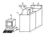
図2は、上記写真処理装置の構成を示す説明図である。図2に示すように、該写真処理装置は、露光部1、印画紙格納部2、現像部3、乾燥部4、およびPC(Personal Computer)5を備えている。
【0023】
印画紙格納部2は、感光材料である印画紙を格納しており、プリント時に、該印画紙を露光部1に供給するためのものである。露光部1は、印画紙格納部2から供給される印画紙に対して、原画像の画像データに応じて走査露光を施すことにより、画像の焼き付けを行うものである。この露光部1の詳細については後述する。
【0024】
現像部3は、焼き付け処理が施された印画紙に対して、各種の現像処理液を施しながら搬送することによって、画像を現像するものである。乾燥部4は、現像処理が施された印画紙を乾燥させるためのものである。PC5は、写真処理装置における諸々の動作を制御する制御部としての機能を果たしているとともに、原画像の画像データを保存する機能や、画像データに対してデータ処理を施す機能などを有している。
【0025】
次に、上記の露光部1の構成について説明する。図3は、露光部1および印画紙格納部2の構成を示す説明図である。図3に示すように、露光部1の上部に位置する印画紙格納部2は、ロール状の印画紙Pを格納するための2つのペーパーマガジン2a・2bを備えている。各ペーパーマガジン2a・2bには、それぞれ異なるサイズの印画紙Pが格納されており、ユーザーが求める出力画像のサイズに応じて、供給する印画紙Pが切り換えられるように設定されている。露光部1は、上記したように、印画紙格納部2から供給される印画紙Pに対して、走査露光を行うものであり、焼付部6と、搬送ローラR1〜R5とを備えている。
【0026】
焼付部6は、搬送ローラR1〜R5によって搬送されている印画紙Pに対して、露光のための光を照射するものである。搬送ローラR1〜R5は、印画紙格納部2から供給された印画紙Pを、焼付部6を経由して現像部3に送り込むためのものである。
【0027】
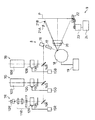
次に、上記の焼付部6の構成について説明する。図4は、焼付部6の概略構成を示す説明図である。該焼付部6は、光源部7R・7G・7B、走査部8、および搬送部9を備えた構成となっている。
【0028】
(光源部の構成)
光源部7Rは、赤色LD(Laser Diode) (光源)10R、レンズ群11R、音響光学変調素子(AOM:Acousto-Optic Modulator )(光ビーム変調手段)12R、調光部13R、およびミラー14Rを備えている。レンズ群11R、AOM12R、および調光部13Rは、赤色LD10Rからミラー14Rに到る光軸上にそれぞれこの順で配置されている。
【0029】
赤色LD10Rは、赤色成分の波長のレーザ光を発する半導体レーザである。また、レンズ群11Rは、赤色LD10から出射した赤色レーザ光を整形し、次のAOM12Rの光入射口に導くためのレンズ群である。
【0030】
AOM12Rは、音波により透明媒質中に作り出された屈折率分布が位相回折格子として働くことによる回折現象、いわゆる音響光学回折を利用した光変調器であり、印加する超音波の強度を変えることによって、回折された光の強度を変調するものである。このAOM12Rには、AOMドライバ(駆動手段)15Rが接続されており、このAOMドライバ15Rから、画像データに応じて振幅が変調された高周波信号が入力される。
【0031】
AOM12Rに対して、AOMドライバ15Rから高周波信号が入力されると、音響光学媒質内に上記高周波信号に応じた超音波が伝搬される。このような音響光学媒質内をレーザ光が透過すると、音響光学効果が作用することによって回折が生じ、高周波信号の振幅に応じた強度のレーザ光がAOM12Rから回折光として出射される。
【0032】
調光部13Rは、AOM12Rを出射した、画像データに応じて変調されたレーザ光の強度を調整する部材であり、例えばNDフィルタや、大きさの異なる複数の開口部が設けられた回転板などによって構成される。半導体レーザや固体レーザなどの発光素子は、安定した状態で発光を行うことのできる光量の範囲が決まっているので、この調光部13Rによる光量の調整によって、印画紙の発色特性に応じて広いダイナミックレンジとなるような光量範囲で露光を行うことが可能となる。
【0033】
ミラー14Rは、調光部13Rを出射したレーザ光を走査部8が配置されている方向に反射させるものである。このミラー14Rは、入射した光のうち、赤色成分の光を反射させるミラーであればどのようなものを用いてもよい。本実施形態では、赤色成分の波長のみからなる赤色レーザ光がミラー14Rに入射するので、ミラー14Rとして、入射した光を全反射させるミラーを用いている。
【0034】
一方、光源部7Gは、緑色SHG(Second HarmonicGeneration)レーザユニット(光源)10G、AOM(光ビーム変調手段)12G、調光部13G、およびダイクロイックミラー14Gを備えている。AOM12G、および調光部13Gは、緑色SHGレーザユニット10Gからダイクロイックミラー14Gに到る光軸上にそれぞれこの順で配置されている。
【0035】
緑色SHGレーザユニット10Gは、緑色成分の波長のレーザ光を出射する光源として機能するものである。この緑色SHGレーザユニット10Gの内部には、図示はしないが、YAGレーザなどの固体レーザ、および該固体レーザから出射されたレーザ光から第2次高調波を取り出す第2次高調波生成部などから構成される波長可変部などが設けられている。例えば、YAGレーザから1064nmの波長のレーザ光が出射される場合、第2次高調波生成部において532nmの波長(緑色成分)のレーザ光が生成され、この第2次高調波成分のレーザ光が出射されることになる。なお、本実施形態の構成では、基本のレーザ光を出射する手段として固体レーザを用いているが、これに限定されるものではなく、例えばLDを用いることも可能である。
【0036】
また、光源部7Rにおいては、赤色LD10RとAOM12Rとの間にレンズ群11Rが設けられている一方、光源部7Gにおいては、このようなレンズ群は設けられていない。しかしながら、レンズ群11Rと同等の機能を有する構成が、緑色SHGレーザユニット10Gの内部に設けられている。
【0037】
AOM12G、および調光部13Gは、光源部7Rにおいて説明したAOM12R、および調光部13Rと同様の機能を有するものである。すなわち、AOM12Gは、緑色SHGレーザユニット10Gから出射されたレーザ光を画像データに応じて変調させるものであり、調光部13Gは、AOM12Gから出射されたレーザ光の光量を調整するものである。
【0038】
ダイクロイックミラー14Gは、調光部13Gを出射した緑色成分のレーザ光を走査部8が配置されている方向に反射させるものである。このダイクロイックミラー14Gは、緑色成分の波長の光のみを反射し、それ以外の波長の光を透過する性質を有している。また、このダイクロイックミラー14Gは、光源部7Rにおけるミラー14Rから走査部8に到る光路上に配置されており、ミラー14Rにおいて反射された赤色のレーザ光は、ダイクロイックミラー14Gを透過して走査部8に到ることになる。すなわち、ダイクロイックミラー14Gから走査部8に向けて進む光は、画像データに応じて変調された赤色成分のレーザ光および緑色成分のレーザ光から構成されることになる。
【0039】
また、光源部7Bは、光源部7Gとほぼ同様の構成となっており、青色SHGレーザユニット(光源)10B、AOM(光ビーム変調手段)12B、調光部13B、およびダイクロイックミラー14Bを備えている。AOM12B、および調光部13Bは、青色SHGレーザユニット10Bからダイクロイックミラー14Bに到る光軸上にそれぞれこの順で配置されている。
【0040】
青色SHGレーザユニット10Bは、青色成分の波長のレーザ光を出射する光源として機能するものであり、緑色SHGレーザユニット10Gとほぼ同様の構成となっている。また、AOM12B、および調光部13Bは、光源部7R・7Gにおいて説明したAOM12R・12G、および調光部13R・13Gと同様の構成のものである。すなわち、AOM12Bは、青色SHGレーザユニット10Bから出射されたレーザ光を画像データに応じて変調させるものであり、調光部13Bは、AOM12Bから出射されたレーザ光の光量を調整するものである。
【0041】
ダイクロイックミラー14Bは、調光部13Bを出射した青色成分のレーザ光を走査部8が配置されている方向に反射させるものである。このダイクロイックミラー14Gは、青色成分の波長の光のみを反射し、それ以外の波長の光を透過する性質を有している。また、このダイクロイックミラー14Bは、ミラー14Rおよびダイクロイックミラー14Gから走査部8に到る光路上に配置されており、ミラー14Rにおいて反射され、ダイクロイックミラー14Gを透過した赤色のレーザ光、およびダイクロイックミラー14Gにおいて反射された緑色のレーザ光は、ダイクロイックミラー14Bを透過して走査部8に到ることになる。すなわち、ダイクロイックミラー14Bから走査部8に向けて進む光は、画像データに応じて変調された赤色成分、緑色成分、青色成分のレーザ光から構成されることになる。
【0042】
なお、本実施形態では、上記のように、各色成分のレーザ光の強度変調を行う構成、すなわち、光ビーム変調手段として、AOM12R・12B・12Gを用いているが、これに限定されるものではなく、各色成分のレーザ光の強度を変化させることが可能な構成であればどのような構成を用いても構わない。例えば、上記のAOMの代わりに、例えば電気光学変調素子(EOM)、磁気光学変調素子(MOM)を適用してレーザ光の強度変調を行う構成としてもかまわない。
【0043】
また、例えば光源部7Rにおいては、AOM12Rを設けずに、赤色LD10Rからの出力自体を直接変調させることによって、レーザ光の強度変調を行う構成としてもよい。この場合、赤色LD10Rからの出力を画像情報に応じて変化させる構成が、光ビーム変調手段に相当することになる。また、言うまでもなく、赤色LDに限定するものではなく、その他の色成分のレーザ光を出射可能なLDを用いることが可能な場合にも、上記と同様の構成とすることができる。
【0044】
(走査部の構成)
走査部8は、反射ミラー16、シリンドリカルレンズ17、ポリゴンミラー(偏向手段)18、およびfθレンズ(光学手段)20を備えた構成となっている。反射ミラー16からポリゴンミラー18に到る光軸上にシリンドリカルレンズ17が配置されているとともに、ポリゴンミラー18から印画紙Pに到る光路上にfθレンズ20が配置されている。
【0045】
反射ミラー16は、光源部7R・7G・7Bにおけるミラー14R、ダイクロイックミラー14G・14Bにおいて反射された赤色成分、緑色成分、青色成分のレーザ光をポリゴンミラー18が配置されている方向へ反射させる部材である。
【0046】
シリンドリカルレンズ17は、反射ミラー16において反射されたレーザ光を、副走査方向においてポリゴンミラー18の反射面上に集光させるレンズである。このシリンドリカルレンズ17は、ポリゴンミラー18の反射面に面倒れ誤差(反射面の法線方向が正常な主走査面からずれる誤差)が生じている場合の補正(面倒れ補正)を行うためのものである。
【0047】
ポリゴンミラー18の反射面に面倒れ誤差が生じていると、印画紙P上でのレーザ光の到達位置が大きく変化してしまい、焼き付け画像にピッチむらが生じることになる。本実施形態では、上記のように、シリンドリカルレンズ17によって副走査方向においてポリゴンミラー18の反射面で一旦集光する構成とし、かつ、ポリゴンミラー18から反射したレーザ光が、fθレンズ20を透過した後に、再び印画紙P上で集光するように、fθレンズ20および印画紙Pを配置している。このような配置とすれば、ポリゴンミラー18の反射面と印画紙Pとが光学的に共役な配置となるので、面倒れによって副走査方向に光束が偏向しても、印画紙P上の同じ位置に光束が結像することになる。言い換えれば、ポリゴンミラー18の反射面の1点から、ある程度の範囲内で任意の方向に光が出射しても、印画紙P上の同じ位置に結像することになる。
【0048】
ポリゴンミラー18は、複数の反射面が正多角形を形成するように設けられた回転体であり、ポリゴンドライバ19によって回転駆動される。反射ミラー16からシリンドリカルレンズ17を介して照射されるレーザ光は、ポリゴンミラー18の1つの反射面で反射されて印画紙P方向に進行する。そして、このポリゴンミラー18からのレーザ光の反射方向は、ポリゴンミラー18の回転に応じて主走査方向に移動する。また、ポリゴンミラー18の回転によって1つの反射面におけるレーザ光の反射が終わると、その反射面に隣合う反射面にレーザ光の照射が移り、同じ範囲で主走査方向にレーザ光の反射方向が移動する。このように、1つの反射面で1つの走査ラインが走査され、隣合う反射面で次の走査ラインが走査されることになるので、副走査方向に隣合う走査ライン同士の間のタイムラグを極めて小さくすることが可能となっている。
【0049】
fθレンズ20は、ポリゴンミラー18から印画紙Pに照射されるレーザ光による走査面の両端近傍での像の歪みを補正するための光学系であり、複数のレンズから構成されている。この走査面の両端近傍での像の歪みは、ポリゴンミラー18から印画紙Pに到る光路の長さが異なることによって生じるものである。
【0050】
また、ポリゴンミラー18から印画紙Pに到るレーザ光の主走査範囲の外側に、同期センサ(同期光検出手段)21A、およびミラー21Bが設けられている。ミラー21Bは、ポリゴンミラー18から見て、主走査の開始点となる方向のすぐ外側となる位置に配置されている。言い換えれば、ポリゴンミラー18における1つの反射面から反射されるレーザ光は、まずミラー21Bに当たり、その直後から印画紙P上に対して主走査方向の露光が行われることになる。
【0051】
また、ミラー21Bの反射面の方向は、ポリゴンミラー18からのレーザ光が同期センサ21Aに照射されるような方向となるように設定されている。また、ポリゴンミラー18からミラー21Bを介して同期センサ21Aに到る光路の長さは、ポリゴンミラー18から印画紙P上における主走査の開始点に到る光路の長さとほぼ等しくなるように設計されている。
【0052】
同期センサ21Aは、光を検出するセンサであり、ポリゴンミラー18からミラー21Bを介してレーザ光が照射されると、その照射タイミングで図示しない制御部に信号を送信する。すなわち、この同期センサ21Aからの出力を監視することによって、印画紙P上における走査タイミングを正確に把握することが可能となる。
【0053】
(搬送部の構成)
搬送部9は、搬送ローラ22、マイクロステップモータ23、およびマイクロステップドライバ24などを備えた構成となっている。搬送ローラ22は、印画紙Pを搬送するローラであり、図4においては、紙面に垂直な方向に印画紙Pを搬送させている。
【0054】
マイクロステップモータ23は、搬送ローラ22を駆動するモータであり、ステッピングモータの一種であるマイクロステップモータによって構成されている。このマイクロステップモータは、回転角の制御を極めて精密に行うことが可能なモータである。
【0055】
マイクロステップドライバ24は、マイクロステップモータ23の回転を駆動するものであり、図示しない制御部からの制御によって、主走査のタイミングと同期するように印画紙Pの副走査方向への搬送速度を制御している。なお、この主走査のタイミングは、上記の同期センサ21Aからの信号に基づいて把握されるものである。
【0056】
以上に示したように、本実施形態における焼付部6は、画像情報に応じて変調された赤色、緑色、青色の各色に対応したレーザ光を、主走査方向に移動させながら印画紙Pを露光するとともに、該印画紙Pを副走査方向に搬送させることによって、印画紙P上に2次元の焼付画像を形成する構成となっている。
【0057】
次に、上記の走査部8において、ポリゴンミラー18からミラー21Bに向けて照射される、同期をとるためのレーザ光(以降、同期光と称する)が、fθレンズ20において内部反射される状態について説明する。図5は、ポリゴンミラー18、fθレンズ20、ミラー21B、同期センサ21A、および像面としての印画紙Pの配置状態を示す説明図である。同図において、ILで示す1点鎖線が、前記したシリンドリカルレンズ17からポリゴンミラー18に照射されるレーザ光の光軸を示している。また、SLで示す1点鎖線が同期光を示している。また、PL1で示す1点鎖線が、主走査による画像光の照射開始点の光軸を示しており、PL2で示す1点鎖線が、主走査による画像光の照射終了点の光軸を示している。すなわち、PL1とPL2との間の領域が、画像光が照射される領域となっている。
【0058】
また、同図に示すように、fθレンズ20は、第1ないし第4のレンズ20A・20B・20C・20Dが光軸方向に並んで配置された構成となっている。このように、fθレンズ20が複数のレンズから構成されているのは、赤色、緑色、青色の各色に対応したレーザ光に対して、収差をなくすようにするためである。
【0059】
ここで、同期光SLが、fθレンズ20内の第3のレンズ20Cで内面反射を行った場合を考えてみる。まず、同期光SLが、第3のレンズ20Cの出射側面において境界面反射をし、この反射光が、第3のレンズ20Cの入射側面で再び境界面反射をしたとする。この反射光は、図5中において、RL1で示す1点鎖線で示される経路を通ることになり、印画紙P上に照射されることがわかる。
【0060】
また、このRL1が、第4のレンズ20Dを透過する際に、さらに内面反射を行うことも考えられる。すなわち、RL1が、第4のレンズ20Dの出射側面において境界面反射をし、この反射光が、第4のレンズ20Dの入射側面で再び境界面反射をしたとする。この反射光は、図5中において、RL2で示す1点鎖線で示される経路を通ることになり、印画紙P上に照射されることがわかる。
【0061】
上記の例では、第3のレンズ20Cおよび第4のレンズ20Dにおける内面反射の例を示したが、その他、第1のレンズ20A、第2のレンズ20Bにおいても、同様の内面反射が行われるとともに、これらの内面反射が多数回繰り返されることにより、同期光による無数の内面反射光が画像光領域に照射されることになる。すなわち、同期光がfθレンズ20を透過する際には、fθレンズ20を構成するレンズにおいて内面反射が繰り返されることによって、画像光が照射される領域にも、同期光の一部が照射されてしまうことになる。そして、上記した無数の反射光のうちの一部が、主走査方向における特定領域に特に集中して照射されるような場合には、この領域に意図しない露光が行われ、印画紙上に副走査方向に延びた色ムラが生じることになる。
【0062】
このような同期光のfθレンズ20での内面反射による不要な露光を抑制するために、本実施形態では、同期光の強度を、同期センサが検出することのできる範囲で最も小さくなるような制御を行っている。
【0063】
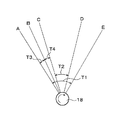
ここで、まず、ポリゴンミラー18の回転に応じて、同期光および画像光が照射される際のタイミングについて説明しておく。図6は、ポリゴンミラー18における1つの反射面から出射される光の範囲を示す説明図である。同図において、ポリゴンミラー18は右回りに回転しているものとし、同期光は、画像光の照射に先立って照射されるものとする。また、A〜Eは、ポリゴンミラー18から照射される光の方向をそれぞれ示しており、ポリゴンミラー18の回転にともなって、AからEまで順に方向が変化していくものとする。
【0064】
同図において、ポリゴンミラー18から光を照射することが可能な期間は、AからEまでの期間T1となっている。また、印画紙P上に実際に画像光を照射する期間は、CからDまでの期間T2となっている。また、同期センサ21Aに光を導くミラー21Bは、Bの方向に配置されている。
【0065】
以上の状態において、まず、Aの方向から同期光としての赤色レーザ光の照射が開始される。そして、期間T3の後に、照射方向がBとなった時点で、この赤色レーザ光が同期センサ21Aにおいて検出され、赤色レーザ光の検出をトリガーとして、同期光としての赤色レーザ光の照射が停止される。
【0066】
同期センサ21Aにおいて同期光が検出されると、その時点からカウンターによるカウントが開始され、このカウンターによって期間T4がカウントされた時点から、画像光の照射が開始される。このカウンターは、ポリゴンミラー18の回転角度に対応した期間をカウントすることが可能なものであれば、どのようなものでもよい。例えば、ポリゴンミラー18の回転を規定するクロックをカウントするカウンターなどが考えられる。
【0067】
このように、同期センサ21Aにおいて同期光が検出された時点から所定期間後に、画像光の照射が開始されるように制御が行われている。これにより、複数の走査ラインのそれぞれにおいて、画像光の照射を全て正確に同じ位置に行うことが可能となっている。
【0068】
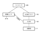
次に、本実施形態における同期光の強度調整を行う構成について説明する。図1は、同期光の強度調整に係わる構成の相関を示すブロック図である。同図において、AOMドライバ15は、前記したAOMドライバ15R・15G・15Bに相当するものであり、AOM12は、前記したAOM12R・12G・12Bに相当するものであり、光源部7は、前記した光源部7R・7G・7Bに相当するものである。
【0069】
コントローラ25は、同期センサ21Aにおける同期光の検出状態を読み出すとともに、AOMドライバ15の動作を制御するブロックである。このコントローラ25は、上記のような制御処理を行うことが可能な構成であればどのようなものを用いてもよいが、例えば、CPU(Central Processing Unit) ベースのコントローラや、ASIC(Application Specific Integrated Circuit) を用いたコントローラなどが考えられる。
【0070】
光源部7から出射されたレーザ光は、AOMドライバ15の制御にしたがってAOMによって光量制御されて、ポリゴンミラー18に向けて出射される。そして、同期光として出射されたレーザ光が同期センサ21Aにおいて検出され、この検出結果がコントローラ25に伝えられる。コントローラ25は、同期センサ21Aからの検出結果に応じて、AOMドライバ15による駆動制御を調整する。
【0071】
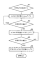
図7は、コントローラ25における、同期光の強度調整に関する処理の流れを示すフローチャートである。この強度調整処理の初期状態としては、光源部7はレーザ光の出射を開始し、定常状態となっているとともに、ポリゴンミラー18も回転を開始し、定常回転となっているものとする。また、同期光としてAOM12から出射されるレーザ光の強度の初期値は、ある程度強度の高い任意の値となっているものとする。
【0072】
まず、ステップ1(以降、S1のように称する)において、同期センサ21Aにおいて同期光が検出された旨を示す同期信号がコントローラ25に入力されたことが確認される。ここで、もし同期信号が確認できない場合には、同期光としてのレーザ光の強度の初期値が低すぎるか、あるいは何らかの機器上のトラブルが発生しているものと判断されるので、処理が中止され、メンテナンスが行われることになる。
【0073】
S1において同期信号が確認されると、AOMドライバ15に対して、AOM12から出力される同期光としてのレーザ光の強度を、1STEP下げるような指示が行われる(S2)。ここで、AOM12から出力されるレーザ光の強度を変える際には、AOM12におけるレーザ光の回折量を変化させることになる。すなわち、レーザ光の強度を下げる場合には、AOM12の回折量が下げられることになる。なお、上記のレーザ光の強度、すなわち回折量の単位変化量としてのSTEPの大きさは、特に限定されるものではないが、STEPが大き過ぎるとレーザ光の強度の制御を正確に行えなくなるので、所望の精度を保つことが可能な範囲でSTEPの大きさを設定すればよい。
【0074】
S2においてレーザ光の強度が下げられた後に、再び同期光の照射が行われ、同期センサ21Aからの同期信号がコントローラ25に入力されたか否かが確認される(S3)。ここで、同期信号が確認された場合(S3においてYES)、S2に戻って、さらにAOM12の回折量を1STEP下げ、S3において同期信号の確認が判断される。このS2およびS3における処理を繰り返すと、AOM12から出射される同期光の強度が徐々に低下していき、この強度があるレベルを下回ると、同期センサ21Aによって同期光の検出が行えなくなる。すなわち、S3において、同期信号を確認することができなくなる(S3においてNO)。
【0075】
S3において、同期信号の確認がされなくなったと判断されると、今度は、AOM12の回折量を1STEP上げるように指示が行われる(S4)。そして、レーザ光の強度が上げられた後に、再び同期光の照射が行われ、同期センサ21Aからの同期信号がコントローラ25に入力されたか否かが確認される(S5)。ここで、同期信号が確認されない場合(S5においてNO)、S4に戻って、さらにAOM12の回折量を1STEP上げ、S5において同期信号の確認が判断される。このS4およびS5における処理は、通常の場合1,2回繰り返されることによって、再び同期信号の確認がされるようになる。
【0076】
そして、S5においてYES、すなわち、同期信号の確認がされた場合、安全率分として、所定の量だけAOM12の回折量を上げる指示が行われる(S6)。これにより、同期光の強度調整に関する処理が完了する。ここで、安全率は、同期センサ21Aの感度の誤差範囲に基づいて設定される。すなわち、同期センサ21Aの感度の誤差範囲は、そのセンサの仕様によって決定されているので、感度が誤差範囲の最悪値となった場合でも、同期信号の確認が可能であるように、安全率が設定される。具体的には、安全率は数パーセント程度に設定されることになるが、この値は、センサの性能に応じて変化しうるものである。
【0077】
なお、上記のフローチャートにおけるS4およびS5の処理は、ヒステリシスを考慮するための処理となっている。すなわち、AOM12の回折量を下げていく場合と上げていく場合とで、同期光の検出状態が異なる場合が考えられるからである。しかしながら、上記のS6における処理において、安全率分として、AOM12の回折量を上げる量を大きく設定すれば、ヒステリシスによる影響を吸収することができるので、この場合には、S4およびS5の処理を省略することも可能である。
【0078】
なお、上記のように、S4およびS5の処理を行う場合には、安全率分の強度の上昇を0とすることも可能である。
【0079】
以上のような同期光の強度調整が行われると、同期光の強度は、同期センサ21Aにおいて検出可能な範囲で最も小さい強度に設定されることになる。したがって、このように同期光の強度が設定された状態で、実際の画像の露光処理を行えば、同期光がfθレンズ20を透過する際に、その一部が、内部反射によって画像光領域に照射されたとしても、元の同期光自体の強度が低くなっているので、露光画像に対する影響をほとんどなくすことができ、人間の目では気がつかない程度とすることができる。
【0080】
以上のような同期光の強度調整は、例えば、1日に1回、1週間に1回、1月に1回、などのように、定期的に行われることが望ましい。このように、定期的に強度調整を行うことによって、経時変化による各構成の特性の変化が生じた場合でも、これに的確に対応することができる。この各構成の特性の変化としては、光源の出力変化、AOMの特性変化、同期センサの検出精度変化などが考えられる。
【0081】
次に、同期光の強度によって、焼付画像の状態がどのように変化するかについて説明する。図8(a)ないし図8(c)は、同期光の強度を3通りに変化させ、各状態でグレー階調の一様な画像を焼き付けた際の、RGB各色成分の濃度の分布を示したグラフである。これらの図において、横軸は、主走査方向での位置を示しており、縦軸は、結像面でのRGB各色成分の光の強度を濃度に換算した濃度換算値を示しており、R,G,Bで示された曲線が、対応する各色成分の濃度分布を示している。なお、これらのデータは、同期光として、R成分のレーザ光を用いた場合のデータとなっている。
【0082】
図8(a)は、同期光の強度を+15に設定した場合の各色成分の濃度分布を示している。ここで、同期光の強度としては、0から+15の範囲で変化させることができるものとする。すなわち、図8(a)に示す状態は、同期光の強度を最大に設定して焼付を行った状態を示している。なお、従来の装置では、一般的に同期光の強度を最大に設定されているので、図8(a)に示す状態は、従来の装置で焼付を行った場合に相当することになる。
【0083】
図8(a)に示すように、主走査方向でのおよそ120〜160mmの位置近傍の領域で、R成分の濃度が上昇していることがわかる。これは、同期光がfθレンズ20の内部で反射され、この内部反射光がある程度集中して上記領域付近に照射されたからであると判断される。この場合、焼付画像には、上記領域付近にシアンの色が強くなった色ムラが生じることになる。
【0084】
図8(b)は、同期光の強度を+7に設定した場合の各色成分の濃度分布を示している。この同期光の強度は、最大の強度よりは低い値であるが、同期センサ21Aにおいて検出可能な最低限の強度よりは高い値となっている。同図に示すように、図8(a)で示す状態よりは、R成分の濃度の上昇の度合いは低くなっているが、依然として、主走査方向でのおよそ120〜160mmの位置近傍の領域で、若干のR成分の濃度の上昇が生じている。したがって、焼付画像には、上記領域付近にシアンの色が若干強められた色ムラが生じることになる。
【0085】
図8(c)は、同期光の強度を+2に設定した場合の各色成分の濃度分布を示している。この同期光の強度は、図7で示したフローチャートによる処理に基づいて設定された強度であり、同期センサ21Aにおいて検出可能な最低限の強度にほぼ等しい強度となっている。同図に示すように、図8(a)や図8(b)に示す濃度分布で生じていたR成分の濃度の上昇は、ほとんど見られなくなっている。すなわち、この場合には、焼付画像に上記のような色ムラは生じず、均一な濃度分布からなる良質な画像を焼き付けることが可能となる。
【0086】
【発明の効果】
以上のように、本発明に係る露光装置は、感光材料を相対的に移動させながら、該感光材料に対して走査露光を行う露光装置において、光ビームを出射する光源と、上記光源から出射される光ビームの強度を変調させる光ビーム変調手段と、上記光ビーム変調手段を駆動する駆動手段と、上記光ビーム変調手段において変調された光ビームを主走査方向に偏向させる偏向手段と、上記偏向手段から出射される光ビームを、上記感光材料上に収束させる光学手段と、上記光ビーム変調手段から上記偏向手段および上記光学手段を介して、上記感光材料に対して照射される光領域とは異なる領域に照射される同期光を検出する同期光検出手段と、上記駆動手段の動作を制御する制御手段とを備え、上記制御手段が、上記同期光の強度を、上記光ビーム変調手段から出射可能な強度の最大値よりも小さい値となるように、上記駆動手段を制御する構成である。
【0087】
これにより、制御手段が、同期光の強度を、光ビーム変調手段から出射可能な強度の最大値よりも小さい値となるように、駆動手段を制御している。したがって、同期光の強度が弱められることになるので、感光材料上に照射されてしまう同期光の光量を落とすことができ、焼付画像の画質の低下を抑制することができるという効果を奏する。
【0088】
本発明に係る露光装置は、上記制御手段が、上記同期光の強度を、上記同期光検出手段において検出可能な同期光の強度の範囲における最低値に、安全率分の値を加えた強度となるように、上記駆動手段を制御する構成である。
【0089】
これにより、請求項1の構成による効果に加えて、同期光の強度を、安全率を考慮した上で最低限の値とすることができるので、同期光の検出を確実に行うことができる範囲で、感光材料上に照射されてしまう同期光の光量を最小限とすることができる。したがって、焼付画像の画質の低下を最大限抑制することができるという効果を奏する。
【0090】
本発明に係る露光装置は、上記制御手段が、上記同期光を上記光ビーム変調手段から出射させる第1のステップと、上記同期光検出手段が、上記第1のステップにおいて上記光ビーム変調手段から出射された同期光を検出したか否かを判定する第2のステップと、上記第2のステップにおいて同期光が検出されたと判定した場合に、上記同期光の強度を、所定の単位変化量分小さくする制御を行うとともに、上記第1のステップからの処理を行う第3のステップと、上記第2のステップにおいて同期光が検出されなかったと判定した場合に、その時点での上記同期光の強度に安全率分の値を加えた値を、同期光の強度として設定する第4のステップとを行い、上記第4のステップにおいて設定された強度の同期光を用いて、走査露光が行われる構成である。
【0091】
これにより、上記の効果に加えて、同期光の強度を、安全率を考慮した上で最低限の値に的確に設定することができる。したがって、同期光の検出を確実に行うことができる範囲で、感光材料上に照射されてしまう同期光の光量を最小限とすることができ、焼付画像の画質の低下を最大限抑制することができるという効果を奏する。
【0092】
本発明に係る露光装置は、上記制御手段が、上記第2のステップにおいて同期光が検出されなかったと判定した場合に、上記同期光の強度を、所定の単位変化量分大きくする制御を、再び同期光検出手段が同期光を検出するまで繰り返し行った後に、上記第4のステップからの処理を行う構成である。
【0093】
これにより、上記の効果に加えて、ヒステリシスの影響、すなわち、同期光の強度を下げていくときの特性と上げていくときの特性とに違いがある場合を考慮して、的確に同期光の強度を設定することができるという効果を奏する。
【0094】
本発明に係る露光装置は、上記光学手段が複数のレンズから構成されている構成である。
【0095】
これにより、上記の効果に加えて、同期光の強度が下げられるので、内部反射光の強度を下げることができ、焼付画像の画質の低下をより効果的に抑制することができるという効果を奏する。
【0096】
本発明に係る写真処理装置は、上記に記載の露光装置と、上記露光装置によって露光が行われた感光材料を、現像処理液を用いることによって現像処理を行う現像処理部と、上記現像処理部において現像処理がなされた感光材料を乾燥させる乾燥部とを備えている構成である。
【0097】
これにより、感光材料に対する露光処理、現像処理、乾燥処理を一元管理の下に連続して行うことができるので、使用者に操作上の負担をかけることなしに、多量の写真を連続的にプリントすることができるという効果を奏する。
【図面の簡単な説明】
【図1】 本発明の実施の一形態における同期光の強度調整に係わる構成の相関を示すブロック図である。
【図2】 本発明の実施の一形態に係る写真処理装置の概略構成を示す斜視図である。
【図3】 上記写真処理装置が備える露光部および印画紙格納部の概略構成を示す説明図である。
【図4】 上記写真処理装置が備える焼付部の概略構成を示す説明図である。
【図5】 ポリゴンミラー、fθレンズ、ミラー、同期センサ、および像面としての印画紙の配置状態を示す説明図である。
【図6】 ポリゴンミラーにおける1つの反射面から出射される光の範囲を示す説明図である。
【図7】 コントローラにおける、同期光の強度調整に関する処理の流れを示すフローチャートである。
【図8】 同図(a)ないし同図(c)は、同期光の強度を3通りに変化させ、各状態でグレー階調の一様な画像を焼き付けた際の、RGB各色成分の濃度の分布を示したグラフである。
【符号の説明】
1 露光部
2 印画紙格納部
3 現像部
4 乾燥部
5 PC
6 焼付部
7・7R・7G・7B 光源部
8 走査部
9 搬送部
10R・10G・10B 赤色LD・緑色SHGレーザユニット・青色SHGレーザユニット(光源)
12・12R・12G・12B AOM(光ビーム変調手段)
14R ミラー
14G・14B ダイクロイックミラー
15・15R・15G・15B AOMドライバ(駆動手段)
16 反射ミラー
17 シリンドリカルレンズ
18 ポリゴンミラー(偏向手段)
19 ポリゴンドライバ
20 fθレンズ(光学手段)
21A 同期センサ(同期光検出手段)
21B ミラー
22 搬送ローラ
23 マイクロステップモータ
24 マイクロステップドライバ
25 コントローラ(制御手段)[0001]
BACKGROUND OF THE INVENTION
The present invention relates to an exposure apparatus for performing exposure by scanning a laser beam modulated in accordance with image information on a photosensitive material such as photographic paper. , Exposure equipment Photo processing device with , And exposure control method It is about.
[0002]
[Prior art]
Conventionally, in the printing of photographs, analog exposure is performed in which printing is performed by irradiating light onto a photographic film on which an original image is recorded and irradiating the photographic paper with light transmitted through the photographic film. In recent years, red, blue, and green monochromatic light has been applied to each pixel based on digital image data obtained by reading an image on a photographic film with a scanner or digital image data obtained by photographing with a digital camera. Digital exposure for printing is performed by irradiating the photographic paper every time.
[0003]
Various configurations have been proposed for performing this digital exposure. As an example, there is a configuration in which photographic paper is scanned and exposed while laser light is modulated in accordance with image data. The image printing apparatus having such a configuration includes a light source that generates laser beams of blue, green, and red colors, and performs a printing operation in the following procedure. First, laser light of each color is modulated based on input digital image data. The modulated laser light is deflected in the main scanning direction by a deflector such as a polygon mirror, and is irradiated onto the photographic paper through an optical system such as an fθ lens. At the same time, scanning exposure is performed by transporting and moving the photographic paper in the sub-scanning direction, and a two-dimensional color image is printed on the photographic paper.
[0004]
[Problems to be solved by the invention]
In the above-described configuration for scanning and exposing the laser beam, a synchronization sensor is provided as a configuration for controlling the irradiation timing of the laser beam. This synchronous sensor receives reflected light of laser light from a reflecting mirror provided on the left or right side of the main scanning range of laser light. By detecting the reception timing of the laser beam by this synchronous sensor, it becomes possible to grasp the main scanning timing of the laser beam by the polygon mirror, thereby enabling accurate control of the irradiation position of the laser beam on the photographic paper. it can.
[0005]
Here, the optical path from the polygon mirror to the reflection mirror is an optical path that passes through a plurality of lenses constituting the fθ lens. In this optical path, reflection occurs at the light incident surface and the light exit surface of the lens, and by repeating this reflection, a part of the light to be irradiated on the reflection mirror may be irradiated within the main scanning range. . Here, as the synchronization laser light emitted toward the synchronization sensor, red light having the best sensitivity in the synchronization sensor is generally used. Therefore, when the internal reflection in the fθ lens as described above occurs, the red synchronization laser light is irradiated onto the photographic paper regardless of the image to be printed. In this case, the image to be printed on the photographic paper has a non-uniformity in which the internal reflection light of the laser beam for synchronization in the fθ lens is particularly concentrated and irradiated with cyan in the vertical direction in the sub-scanning direction ( Flare) will occur, and the quality of the printed image will be significantly reduced.
[0006]
The present invention has been made to solve the above-described problems, and an object of the present invention is to deflect laser light by a deflecting means such as a polygon mirror, and onto a photographic paper as a photosensitive material by an optical means such as an fθ lens. To provide an exposure apparatus that does not deteriorate the quality of a printed image by a synchronizing light for synchronizing scanning exposure in an exposure apparatus that performs scanning exposure by irradiation, and a photo processing apparatus including the exposure apparatus. is there.
[0007]
[Means for Solving the Problems]
To solve the above problem, The present invention In the exposure apparatus that performs scanning exposure on the photosensitive material while relatively moving the photosensitive material, the exposure apparatus modulates the light source that emits the light beam and the intensity of the light beam emitted from the light source. A light beam modulating means; a driving means for driving the light beam modulating means; a deflecting means for deflecting the light beam modulated by the light beam modulating means in a main scanning direction; and a light beam emitted from the deflecting means. Optical means for converging on the photosensitive material, and synchronous light irradiated to an area different from the light area irradiated to the photosensitive material from the light beam modulating means via the deflecting means and the optical means. Synchronization light detection means and control means for controlling the operation of the drive means, and the control means can emit the intensity of the synchronization light from the light beam modulation means. So that a value smaller than the maximum value of the intensity, is characterized by controlling the drive means.
[0008]
In the above configuration, the light beam emitted from the light source is modulated in accordance with the image information by the light beam modulating unit, deflected in the main scanning direction by the deflecting unit, and converged on the photosensitive material through the optical unit. Scanning exposure is performed. In addition, the synchronization light detection unit is configured to detect synchronization light applied to an area different from the light area applied to the photosensitive material. Thus, by detecting the synchronization light by the synchronization light detection means, the irradiation timing of the light beam irradiated onto the photosensitive material can be accurately controlled.
[0009]
In such a configuration, when the synchronization light passes through the optical means, a part of the synchronization light may be irradiated onto the photosensitive material due to unintentional reflection generated inside the optical means. Unexpected exposure is performed on the photosensitive material by a part of the synchronous light irradiated onto the photosensitive material, and the image quality of the printed image is deteriorated. On the other hand, in the above configuration, the control unit controls the driving unit so that the intensity of the synchronization light is smaller than the maximum intensity that can be emitted from the light beam modulation unit. Thereby, since the intensity | strength of synchronous light will be weakened, the light quantity of the synchronous light irradiated on a photosensitive material can be dropped. Therefore, it is possible to suppress the deterioration of the image quality of the printed image.
[0010]
Of the present invention The exposure equipment the above In the configuration, the control means, so that the intensity of the synchronization light becomes the intensity obtained by adding a value corresponding to the safety factor to the lowest value in the range of the intensity of the synchronization light detectable by the synchronization light detection means, The driving means is controlled.
[0011]
In the above configuration, the intensity of the synchronization light is controlled by the control means so as to be the intensity obtained by adding the value corresponding to the safety factor to the lowest value in the range of the intensity of the synchronization light that can be detected by the synchronization light detection means. Yes. Therefore, since the intensity of the sync light can be set to the minimum value in consideration of the safety factor, the sync light that is irradiated on the photosensitive material within a range in which the sync light can be reliably detected. The amount of light can be minimized. Therefore, it is possible to suppress the deterioration of the image quality of the printed image as much as possible.
[0012]
In addition, the present invention The exposure equipment of the above In the configuration, the control means emits the synchronization light from the light beam modulation means, and the synchronization light detection means outputs the synchronization light emitted from the light beam modulation means in the first step. A second step for determining whether or not light is detected, and a control for reducing the intensity of the synchronizing light by a predetermined unit change amount when it is determined that the synchronizing light is detected in the second step. And performing a process from the first step, and if it is determined that no sync light has been detected in the second step, the intensity of the sync light at that time is divided by a safety factor. And a fourth step of setting a value obtained by adding the above value as the intensity of the synchronization light, and scanning exposure is performed using the synchronization light having the intensity set in the fourth step. It is a symptom.
[0013]
According to the above configuration, the intensity of the synchronization light is gradually lowered from the intensity that can be detected by the synchronization light detection means, and the value corresponding to the safety factor is added to the intensity when the synchronization light detection means cannot be detected. This value is set as the intensity of the synchronous light used during actual scanning exposure. Therefore, the intensity of the synchronization light can be accurately set to the minimum value in consideration of the safety factor. Therefore, it is possible to minimize the amount of the synchronization light that is irradiated onto the photosensitive material within a range in which the synchronization light can be reliably detected, and to suppress the deterioration of the image quality of the printed image to the maximum. it can.
[0014]
Furthermore, the present invention Exposure equipment ,Up When the control means determines that no sync light is detected in the second step, the sync light detection means again controls the sync light to increase the intensity of the sync light by a predetermined unit change amount. After the process is repeated until detection, the process from the fourth step is performed.
[0015]
In the above configuration, the intensity of the sync light is gradually lowered, and when the sync light detecting means cannot be detected, the sync light intensity is increased again, and when the sync light detecting means comes to detect again, The value of the safety factor is added to set the intensity of the synchronization light. Accordingly, it is possible to accurately set the intensity of the synchronization light in consideration of the influence of hysteresis, that is, the case where there is a difference between the characteristics when the intensity of the synchronization light is lowered and the characteristics when it is increased. .
[0016]
Of the present invention The exposure equipment the above In the construction, the optical means is composed of a plurality of lenses.
[0017]
In said structure, the optical means is comprised from the some lens. In such a configuration, normally, unintentional internal reflection that occurs when the synchronization light passes through the optical means occurs more, and the amount of the synchronization light that is irradiated onto the photosensitive material increases. Problems arise. On the other hand, according to the above configuration, since the intensity of the synchronization light can be reduced, the intensity of the internally reflected light can be reduced, and the deterioration of the image quality of the printed image can be more effectively suppressed.
[0018]
The present invention The photo processing equipment the above The exposure apparatus according to 1), the photosensitive material exposed by the exposure apparatus, a development processing unit that performs development processing by using a development processing solution, and the photosensitive material that has undergone development processing in the development processing unit are dried. And a drying section.
[0019]
According to the above configuration, the exposure processing, development processing, and drying processing for the photosensitive material can be performed continuously under a unified management, so that a large number of photographs can be taken without placing an operational burden on the user. Can be printed continuously.
[0020]
DETAILED DESCRIPTION OF THE INVENTION
An embodiment of the present invention will be described below with reference to FIGS.
[0021]
The photographic processing apparatus according to this embodiment is a digital photographic printer that prints an original image on a photosensitive material by printing, developing and drying the photographic paper as the photosensitive material based on the image data of the original image. It is.
[0022]
FIG. 2 is an explanatory diagram showing the configuration of the photographic processing apparatus. As shown in FIG. 2, the photographic processing apparatus includes an exposure unit 1, a photographic
[0023]
The photographic
[0024]
The developing
[0025]
Next, the configuration of the exposure unit 1 will be described. FIG. 3 is an explanatory diagram showing the configuration of the exposure unit 1 and the photographic
[0026]
The
[0027]
Next, the structure of said
[0028]
(Configuration of light source)
The
[0029]
The
[0030]
The
[0031]
When a high frequency signal is input from the
[0032]
The
[0033]
The
[0034]
On the other hand, the light source unit 7G includes a green SHG (Second Harmonic Generation) laser unit (light source) 10G, an AOM (light beam modulation means) 12G, a
[0035]
The green
[0036]
Further, in the
[0037]
The
[0038]
The
[0039]
The
[0040]
The blue
[0041]
The dichroic mirror 14B reflects the blue component laser light emitted from the light control unit 13B in the direction in which the scanning unit 8 is disposed. This
[0042]
In the present embodiment, as described above, the configuration for modulating the intensity of the laser light of each color component, that is, the
[0043]
For example, the
[0044]
(Configuration of scanning unit)
The scanning unit 8 includes a
[0045]
The
[0046]
The
[0047]
If a surface tilt error has occurred on the reflection surface of the
[0048]
The
[0049]
The
[0050]
In addition, a synchronization sensor (synchronous light detection means) 21A and a
[0051]
Further, the direction of the reflection surface of the
[0052]
The
[0053]
(Conveyor configuration)
The
[0054]
The
[0055]
The
[0056]
As described above, the
[0057]
Next, in the scanning unit 8, a state in which laser light for synchronization (hereinafter referred to as synchronization light) irradiated from the
[0058]
Further, as shown in the figure, the
[0059]
Here, consider a case where the synchronization light SL is internally reflected by the
[0060]
Moreover, when this RL1 permeate | transmits the
[0061]
In the above example, the example of the internal reflection in the
[0062]
In order to suppress unnecessary exposure due to internal reflection of the synchronization light at the
[0063]
Here, the timing when the synchronization light and the image light are irradiated according to the rotation of the
[0064]
In the figure, a period during which light can be irradiated from the
[0065]
In the above state, first, irradiation of red laser light as synchronization light is started from the direction A. Then, when the irradiation direction becomes B after the period T3, the red laser light is detected by the
[0066]
When the synchronization light is detected by the
[0067]
As described above, the control is performed so that the irradiation of the image light is started after a predetermined period from the time when the synchronization light is detected by the
[0068]
Next, a configuration for adjusting the intensity of the synchronization light in this embodiment will be described. FIG. 1 is a block diagram showing the correlation of the configuration related to the intensity adjustment of the synchronization light. In the figure, an AOM driver 15 corresponds to the
[0069]
The
[0070]
The laser light emitted from the light source unit 7 is controlled by the AOM according to the control of the AOM driver 15 and emitted toward the
[0071]
FIG. 7 is a flowchart showing the flow of processing relating to the intensity adjustment of the synchronization light in the
[0072]
First, in step 1 (hereinafter referred to as S1), it is confirmed that a synchronization signal indicating that synchronization light has been detected by the
[0073]
When the synchronization signal is confirmed in S1, an instruction is given to the AOM driver 15 to decrease the intensity of the laser beam as the synchronization light output from the
[0074]
After the intensity of the laser beam is lowered in S2, the synchronization light is irradiated again, and it is confirmed whether or not the synchronization signal from the
[0075]
If it is determined in S3 that the synchronization signal is no longer confirmed, an instruction is given to increase the diffraction amount of the
[0076]
If YES in S5, that is, if the synchronization signal is confirmed, an instruction is given to increase the diffraction amount of the
[0077]
In addition, the process of S4 and S5 in said flowchart is a process for considering a hysteresis. That is, the case where the detection state of the synchronous light is different between the case where the diffraction amount of the
[0078]
As described above, when the processes of S4 and S5 are performed, the increase in the intensity corresponding to the safety factor can be set to zero.
[0079]
When the intensity adjustment of the synchronization light as described above is performed, the intensity of the synchronization light is set to the smallest intensity that can be detected by the
[0080]
The intensity adjustment of the synchronization light as described above is desirably performed periodically, such as once a day, once a week, once a month, and the like. In this way, by periodically adjusting the intensity, even when the characteristics of each component change due to changes over time, it is possible to accurately cope with this. As the change in the characteristics of each component, a change in the output of the light source, a change in the characteristics of the AOM, a change in detection accuracy of the synchronous sensor, and the like can be considered.
[0081]
Next, how the state of the burned image changes depending on the intensity of the synchronous light will be described. FIG. 8A to FIG. 8C show the distribution of the density of each RGB color component when the intensity of the synchronous light is changed in three ways and an image with a uniform gray gradation is printed in each state. It is a graph. In these drawings, the horizontal axis indicates the position in the main scanning direction, and the vertical axis indicates the density conversion value obtained by converting the light intensity of each of the RGB color components on the imaging surface into the density. , G, and B show the density distributions of the corresponding color components. These data are data when an R component laser beam is used as the synchronization light.
[0082]
FIG. 8A shows the density distribution of each color component when the intensity of the synchronous light is set to +15. Here, the intensity of the synchronization light can be changed in the range of 0 to +15. That is, the state shown in FIG. 8A shows a state in which the image is baked with the synchronization light intensity set to the maximum. In the conventional apparatus, since the intensity of the synchronization light is generally set to the maximum, the state shown in FIG. 8A corresponds to the case where the printing is performed in the conventional apparatus.
[0083]
As shown in FIG. 8A, it can be seen that the density of the R component is increased in a region in the vicinity of a position of approximately 120 to 160 mm in the main scanning direction. It is determined that this is because the synchronous light is reflected inside the
[0084]
FIG. 8B shows the density distribution of each color component when the intensity of the synchronous light is set to +7. The intensity of the synchronization light is lower than the maximum intensity, but is higher than the minimum intensity that can be detected by the
[0085]
FIG. 8C shows the density distribution of each color component when the intensity of the synchronous light is set to +2. The intensity of the synchronization light is an intensity set based on the processing according to the flowchart shown in FIG. 7, and is substantially equal to the minimum intensity detectable by the
[0086]
【The invention's effect】
As above Book An exposure apparatus according to the invention is an exposure apparatus that performs scanning exposure on a photosensitive material while relatively moving the photosensitive material, and includes a light source that emits a light beam and an intensity of the light beam emitted from the light source. Light beam modulating means for modulating, driving means for driving the light beam modulating means, deflecting means for deflecting the light beam modulated by the light beam modulating means in the main scanning direction, and light emitted from the deflecting means An optical means for converging the beam on the photosensitive material, and an area different from the light area irradiated on the photosensitive material from the light beam modulating means via the deflecting means and the optical means. A synchronizing light detecting means for detecting the synchronizing light; and a control means for controlling the operation of the driving means. So that a value smaller than the maximum value of the possible morphism strength, a configuration for controlling said drive means.
[0087]
Thereby, the control means controls the drive means so that the intensity of the synchronization light becomes smaller than the maximum intensity that can be emitted from the light beam modulation means. Accordingly, since the intensity of the synchronization light is weakened, it is possible to reduce the amount of the synchronization light that is irradiated onto the photosensitive material, and it is possible to suppress the deterioration of the image quality of the printed image.
[0088]
Book In the exposure apparatus according to the invention, the control means has an intensity obtained by adding the value of the safety factor to the lowest value in the range of the intensity of the synchronization light that can be detected by the synchronization light detection means. Thus, it is the structure which controls the said drive means.
[0089]
Thereby, in addition to the effect by the structure of Claim 1, since the intensity | strength of synchronous light can be made into the minimum value in consideration of a safety factor, the range which can detect synchronous light reliably Thus, the amount of synchronous light that is irradiated onto the photosensitive material can be minimized. Therefore, it is possible to suppress the deterioration of the image quality of the burned image to the maximum.
[0090]
Book In the exposure apparatus according to the invention, the control means emits the synchronization light from the light beam modulation means, and the synchronization light detection means emits the light beam modulation means from the light beam modulation means in the first step. A second step for determining whether or not the detected synchronization light has been detected; and when it is determined that the synchronization light has been detected in the second step, the intensity of the synchronization light is decreased by a predetermined unit change amount. If it is determined that the synchronization light is not detected in the third step and the second step, the intensity of the synchronization light at that time is determined. A value obtained by adding a value corresponding to the safety factor is set as a synchronizing light intensity, and a fourth step is performed, and scanning exposure is performed using the synchronizing light having the intensity set in the fourth step. It is formed.
[0091]
This above In addition to the effect, the intensity of the sync light can be accurately set to the minimum value in consideration of the safety factor. Therefore, it is possible to minimize the amount of the synchronization light that is irradiated onto the photosensitive material within a range in which the synchronization light can be reliably detected, and to suppress the deterioration of the image quality of the printed image to the maximum. There is an effect that can be done.
[0092]
Book In the exposure apparatus according to the invention, when the control unit determines that the synchronization light is not detected in the second step, the control for increasing the intensity of the synchronization light by a predetermined unit change amount is synchronized again. This is a configuration in which the processing from the fourth step is performed after it is repeated until the light detection means detects synchronous light.
[0093]
This above In addition to the effect, set the sync light intensity accurately taking into account the effect of hysteresis, that is, when there is a difference between the characteristics when the sync light intensity is lowered and when it is raised. There is an effect that can be.
[0094]
Book The exposure apparatus according to the present invention is configured such that the optical means is composed of a plurality of lenses.
[0095]
This above In addition to the effect, the intensity of the synchronization light can be reduced, so that the intensity of the internal reflection light can be reduced, and the deterioration of the image quality of the printed image can be more effectively suppressed.
[0096]
Book The photographic processing apparatus according to the invention is: the above The exposure apparatus described in 1), a development processing unit that performs development processing by using a development processing solution for the photosensitive material that has been exposed by the exposure apparatus, and a photosensitive material that has been subjected to development processing by the development processing unit are dried. It is the structure provided with the drying part to be made.
[0097]
As a result, exposure processing, development processing, and drying processing for photosensitive materials can be performed continuously under a centralized control, so a large number of photos can be printed continuously without burdening the user. There is an effect that can be done.
[Brief description of the drawings]
FIG. 1 is a block diagram showing a correlation of configurations related to synchronization light intensity adjustment in an embodiment of the present invention.
FIG. 2 is a perspective view showing a schematic configuration of a photographic processing apparatus according to an embodiment of the present invention.
FIG. 3 is an explanatory diagram showing a schematic configuration of an exposure unit and a photographic paper storage unit included in the photographic processing apparatus.
FIG. 4 is an explanatory diagram showing a schematic configuration of a printing unit provided in the photographic processing apparatus.
FIG. 5 is an explanatory diagram showing an arrangement state of a polygon mirror, an fθ lens, a mirror, a synchronization sensor, and photographic paper as an image plane.
FIG. 6 is an explanatory diagram showing a range of light emitted from one reflecting surface in a polygon mirror.
FIG. 7 is a flowchart showing a flow of processing relating to intensity adjustment of synchronous light in a controller.
FIG. 8A to FIG. 8C show the density of each color component of RGB when a gray-scale uniform image is printed in each state by changing the sync light intensity in three ways. It is the graph which showed distribution of.
[Explanation of symbols]
1 Exposure section
2 photographic paper storage
3 Development section
4 Drying section
5 PC
6 Baking parts
7,7R, 7G, 7B Light source
8 Scanning part
9 Transport section
10R / 10G / 10B Red LD / Green SHG Laser Unit / Blue SHG Laser Unit (Light Source)
12, 12R, 12G, 12B AOM (light beam modulation means)
14R mirror
14G / 14B Dichroic Mirror
15.15R.15G.15B AOM driver (driving means)
16 Reflection mirror
17 Cylindrical lens
18 Polygon mirror (deflection means)
19 Polygon driver
20 fθ lens (optical means)
21A Synchronization sensor (synchronous light detection means)
21B mirror
22 Transport roller
23 Microstepping motor
24 Microstep driver
25 Controller (control means)
Claims (4)
光ビームを出射する光源と、
上記光源から出射される光ビームの強度を変調させる光ビーム変調手段と、
上記光ビーム変調手段を駆動する駆動手段と、
上記光ビーム変調手段において変調された光ビームを主走査方向に偏向させる偏向手段と、
上記偏向手段から出射される光ビームを上記感光材料上に収束させる光学手段と、
上記光ビーム変調手段から上記偏向手段および上記光学手段を介して、上記感光材料に対して照射される光領域とは異なる領域に照射される同期光を検出する同期光検出手段と、
上記駆動手段の動作を制御する制御手段とを備え、
上記制御手段が、
上記同期光を上記光ビーム変調手段から出射させる第1のステップと、
上記同期光検出手段が、上記第1のステップにおいて上記光ビーム変調手段から出射された同期光を検出したか否かを判定する第2のステップ(S1)と、
上記第2のステップ(S1)において同期光が検出されたと判定した場合に、上記同期光の強度を、所定の単位変化量分小さくする制御を行う第3のステップ(S2)と、
上記第3のステップ(S2)により同期光の強度が下げられた後に、再び上記同期光検出手段が同期光を検出したか否かを判定し、同期光を検出したときには上記同期光の強度を所定の単位変化量分小さくする制御を、同期光を検出しなくなるまで繰り返す第4のステップ(S3)と、
上記第4のステップ(S3)により同期光が検出されなかったと判定した場合に、上記同期光の強度を、所定の単位変化量分大きくする制御を行う第5のステップ(S4)と、
上記第5のステップ(S4)により同期光の強度が上げられた後に、再び同期光検出手段が同期光を検出したか否かを判定し、再び同期光を検出するまで上記同期光の強度を、所定の単位変化量分大きくする制御を繰り返し行う第6のステップ(S5)と、
上記第6のステップ(S5)により検出された、上記同期光検出手段において検出可能な同期光の強度の範囲における最低値に、安全率分の値を加えた強度を、同期光の強度として設定する第7のステップ(S6)とを行い、
上記第7のステップ(S6)において設定された強度の同期光を用いて、走査露光が行われることを特徴とする露光装置。In an exposure apparatus that performs scanning exposure on the photosensitive material while relatively moving the photosensitive material,
A light source that emits a light beam;
A light beam modulating means for modulating the intensity of the light beam emitted from the light source;
Driving means for driving the light beam modulating means;
Deflection means for deflecting the light beam modulated in the light beam modulation means in the main scanning direction;
Optical means for converging the light beam emitted from the deflection means on the photosensitive material;
Synchronized light detecting means for detecting synchronized light irradiated to an area different from the light area irradiated to the photosensitive material from the light beam modulating means via the deflecting means and the optical means;
Control means for controlling the operation of the driving means,
The control means is
A first step of emitting the synchronizing light from the light beam modulating means;
A second step (S1) for determining whether or not the synchronization light detection means has detected the synchronization light emitted from the light beam modulation means in the first step;
When it is determined that light is synchronously detected in the second step (S1), the intensity of the synchronization light, and the third step intends row control to reduce predetermined unit amount of change (S2),
After the sync light intensity is lowered in the third step (S2), it is determined again whether the sync light detecting means has detected the sync light, and when the sync light is detected, the sync light intensity is detected. 4th step (S3) which repeats control which makes small by predetermined unit change amount until it stops detecting synchronous light,
A fifth step (S4) for performing control to increase the intensity of the synchronization light by a predetermined unit change amount when it is determined that the synchronization light is not detected in the fourth step (S3) ;
After raised the intensity of the synchronization light by the fifth step (S4), the intensity of the synchronization light to again synchronize the light detecting means determines whether it has detected the synchronization light, detecting the synchronous light again , sixth step intends repeated line control to increase the predetermined unit amount of change and (S5),
The intensity obtained by adding the value corresponding to the safety factor to the lowest value in the range of the intensity of the synchronization light detected by the synchronization light detection means detected in the sixth step (S5) is set as the intensity of the synchronization light. And the seventh step (S6)
An exposure apparatus characterized in that scanning exposure is performed using the synchronous light having the intensity set in the seventh step (S6) .
上記露光装置によって露光が行われた感光材料を、現像処理液を用いることによって現像処理を行う現像処理部と、
上記現像処理部において現像処理がなされた感光材料を乾燥させる乾燥部とを備えていることを特徴とする写真処理装置。An exposure apparatus according to claim 1 or 2,
A development processing unit for performing development processing on the photosensitive material exposed by the exposure apparatus by using a development processing solution;
A photographic processing apparatus comprising: a drying unit that dries the photosensitive material that has undergone development processing in the development processing unit.
上記光源から出射される光ビームの強度を変調させる光ビーム変調手段と、
上記光ビーム変調手段を駆動する駆動手段と、
上記光ビーム変調手段において変調された光ビームを主走査方向に偏向させる偏向手段と、
上記偏向手段から出射される光ビームを感光材料上に収束させる光学手段と、
上記光ビーム変調手段から上記偏向手段および上記光学手段を介して、上記感光材料に対して照射される光領域とは異なる領域に照射される同期光を検出する同期光検出手段と、
上記駆動手段の動作を制御する制御手段とを備え、
上記感光材料を相対的に移動させながら、該感光材料に対して走査露光を行う露光装置の露光制御方法において、
上記制御手段が、
上記同期光を上記光ビーム変調手段から出射させる第1のステップと、
上記同期光検出手段が、上記第1のステップにおいて上記光ビーム変調手段から出射された同期光を検出したか否かを判定する第2のステップ(S1)と、
上記第2のステップ(S1)において同期光が検出されたと判定した場合に、上記同期光の強度を、所定の単位変化量分小さくする制御を行う第3のステップ(S2)と、
上記第3のステップ(S2)により同期光の強度が下げられた後に、再び上記同期光検出手段が同期光を検出したか否かを判定し、同期光を検出したときには上記同期光の強度を所定の単位変化量分小さくする制御を、同期光を検出しなくなるまで繰り返す第4のステップ(S3)と、
上記第4のステップ(S3)により同期光が検出されなかったと判定した場合に、上記同期光の強度を、所定の単位変化量分大きくする制御を行う第5のステップ(S4)と、
上記第5のステップ(S4)により同期光の強度が上げられた後に、再び同期光検出手段が同期光を検出したか否かを判定し、再び同期光を検出するまで上記同期光の強度を、所定の単位変化量分大きくする制御を繰り返し行う第6のステップ(S5)と、
上記第6のステップ(S5)により検出された、上記同期光検出手段において検出可能な同期光の強度の範囲における最低値に、安全率分の値を加えた強度を、同期光の強度として設定する第7のステップ(S6)とを行い、
上記第7のステップ(S6)において設定された強度の同期光を用いて、走査露光の制御を行うようにしたことを特徴とする露光制御方法。A light source that emits a light beam;
A light beam modulating means for modulating the intensity of the light beam emitted from the light source;
Driving means for driving the light beam modulating means;
Deflection means for deflecting the light beam modulated in the light beam modulation means in the main scanning direction;
Optical means for converging the light beam emitted from the deflecting means on the photosensitive material;
Synchronized light detecting means for detecting synchronized light irradiated to an area different from the light area irradiated to the photosensitive material from the light beam modulating means via the deflecting means and the optical means;
Control means for controlling the operation of the driving means,
In an exposure control method of an exposure apparatus that performs scanning exposure on the photosensitive material while relatively moving the photosensitive material,
The control means is
A first step of emitting the synchronizing light from the light beam modulating means;
A second step (S1) for determining whether or not the synchronization light detection means has detected the synchronization light emitted from the light beam modulation means in the first step;
When it is determined that light is synchronously detected in the second step (S1), the intensity of the synchronization light, and the third step intends row control to reduce predetermined unit amount of change (S2),
After the sync light intensity is lowered in the third step (S2), it is determined again whether the sync light detecting means has detected the sync light, and when the sync light is detected, the sync light intensity is detected. 4th step (S3) which repeats control which makes small by predetermined unit change amount until it stops detecting synchronous light,
A fifth step (S4) for performing control to increase the intensity of the synchronization light by a predetermined unit change amount when it is determined that the synchronization light is not detected in the fourth step (S3) ;
After raised the intensity of the synchronization light by the fifth step (S4), the intensity of the synchronization light to again synchronize the light detecting means determines whether it has detected the synchronization light, detecting the synchronous light again , sixth step intends repeated line control to increase the predetermined unit amount of change and (S5),
The intensity obtained by adding the value corresponding to the safety factor to the lowest value in the range of the intensity of the synchronization light detected by the synchronization light detection means detected in the sixth step (S5) is set as the intensity of the synchronization light. And the seventh step (S6)
An exposure control method characterized in that scanning exposure is controlled using the synchronized light having the intensity set in the seventh step (S6) .
Priority Applications (1)
| Application Number | Priority Date | Filing Date | Title |
|---|---|---|---|
| JP2001045727A JP4635349B2 (en) | 2001-02-21 | 2001-02-21 | Exposure apparatus, photographic processing apparatus including the same, and exposure control method |
Applications Claiming Priority (1)
| Application Number | Priority Date | Filing Date | Title |
|---|---|---|---|
| JP2001045727A JP4635349B2 (en) | 2001-02-21 | 2001-02-21 | Exposure apparatus, photographic processing apparatus including the same, and exposure control method |
Publications (2)
| Publication Number | Publication Date |
|---|---|
| JP2002244056A JP2002244056A (en) | 2002-08-28 |
| JP4635349B2 true JP4635349B2 (en) | 2011-02-23 |
Family
ID=18907460
Family Applications (1)
| Application Number | Title | Priority Date | Filing Date |
|---|---|---|---|
| JP2001045727A Expired - Lifetime JP4635349B2 (en) | 2001-02-21 | 2001-02-21 | Exposure apparatus, photographic processing apparatus including the same, and exposure control method |
Country Status (1)
| Country | Link |
|---|---|
| JP (1) | JP4635349B2 (en) |
Families Citing this family (2)
| Publication number | Priority date | Publication date | Assignee | Title |
|---|---|---|---|---|
| JP4910777B2 (en) * | 2007-03-01 | 2012-04-04 | Nkワークス株式会社 | Exposure equipment |
| US11454836B2 (en) * | 2018-06-29 | 2022-09-27 | Via Mechanics, Ltd. | Laser processing apparatus and laser processing method |
Family Cites Families (4)
| Publication number | Priority date | Publication date | Assignee | Title |
|---|---|---|---|---|
| JPS62219757A (en) * | 1986-03-19 | 1987-09-28 | Minolta Camera Co Ltd | Optical scanning device |
| JPH08244274A (en) * | 1995-03-09 | 1996-09-24 | Fuji Xerox Co Ltd | Digital image former |
| JPH10202943A (en) * | 1997-01-20 | 1998-08-04 | Ricoh Co Ltd | Electrophotographic equipment |
| JPH1142814A (en) * | 1997-07-25 | 1999-02-16 | Ricoh Co Ltd | Image forming device |
-
2001
- 2001-02-21 JP JP2001045727A patent/JP4635349B2/en not_active Expired - Lifetime
Also Published As
| Publication number | Publication date |
|---|---|
| JP2002244056A (en) | 2002-08-28 |
Similar Documents
| Publication | Publication Date | Title |
|---|---|---|
| JP4635349B2 (en) | Exposure apparatus, photographic processing apparatus including the same, and exposure control method | |
| US6552741B2 (en) | Optical scanning device, image scanning method and photographic processing device | |
| JP2002240350A (en) | Exposure apparatus and photographic processing apparatus having the same | |
| JP2006053240A (en) | Laser light modulator | |
| JP4492253B2 (en) | Laser exposure equipment | |
| JP3783586B2 (en) | Exposure equipment | |
| JP3669294B2 (en) | Photo processing device | |
| JP2008209687A (en) | Laser output adjustment method | |
| JP3724434B2 (en) | Exposure amount adjustment method | |
| JP2001350207A (en) | Exposure apparatus, photographic processing apparatus and exposure method | |
| JP3692982B2 (en) | Exposure correction calculation device, exposure correction calculation method, exposure device, and image output device | |
| JP2007118329A (en) | Exposure method and apparatus, and photographic processing apparatus using the same | |
| JP3788342B2 (en) | Exposure amount adjustment method | |
| JP2001350206A (en) | Exposure apparatus, photographic processing apparatus and exposure method | |
| JP2001330892A (en) | PRINT HEAD AND PHOTOGRAPHIC PROCESSOR HAVING THE SAME | |
| JP2002341460A (en) | Exposure apparatus, photographic processing apparatus and exposure method | |
| JP2003050370A (en) | Image forming device | |
| JPH05289011A (en) | Image recorder | |
| JP2002036629A (en) | Image forming device | |
| KR100243145B1 (en) | Compact color printer | |
| JP2002052756A (en) | Image forming method and image forming apparatus | |
| JP2007017624A (en) | Optical scanning device | |
| JP2006154036A (en) | Laser exposure equipment | |
| JP2006305753A (en) | Exposure equipment | |
| JP2006130867A (en) | Photo processing device |
Legal Events
| Date | Code | Title | Description |
|---|---|---|---|
| A621 | Written request for application examination |
Free format text: JAPANESE INTERMEDIATE CODE: A621 Effective date: 20071130 |
|
| RD02 | Notification of acceptance of power of attorney |
Free format text: JAPANESE INTERMEDIATE CODE: A7422 Effective date: 20100312 |
|
| RD04 | Notification of resignation of power of attorney |
Free format text: JAPANESE INTERMEDIATE CODE: A7424 Effective date: 20100319 |
|
| A977 | Report on retrieval |
Free format text: JAPANESE INTERMEDIATE CODE: A971007 Effective date: 20100528 |
|
| A131 | Notification of reasons for refusal |
Free format text: JAPANESE INTERMEDIATE CODE: A131 Effective date: 20100608 |
|
| A521 | Request for written amendment filed |
Free format text: JAPANESE INTERMEDIATE CODE: A523 Effective date: 20100729 |
|
| A131 | Notification of reasons for refusal |
Free format text: JAPANESE INTERMEDIATE CODE: A131 Effective date: 20100817 |
|
| A521 | Request for written amendment filed |
Free format text: JAPANESE INTERMEDIATE CODE: A523 Effective date: 20101006 |
|
| TRDD | Decision of grant or rejection written | ||
| A01 | Written decision to grant a patent or to grant a registration (utility model) |
Free format text: JAPANESE INTERMEDIATE CODE: A01 Effective date: 20101026 |
|
| A01 | Written decision to grant a patent or to grant a registration (utility model) |
Free format text: JAPANESE INTERMEDIATE CODE: A01 |
|
| A61 | First payment of annual fees (during grant procedure) |
Free format text: JAPANESE INTERMEDIATE CODE: A61 Effective date: 20101108 |
|
| FPAY | Renewal fee payment (event date is renewal date of database) |
Free format text: PAYMENT UNTIL: 20131203 Year of fee payment: 3 |
|
| R150 | Certificate of patent or registration of utility model |
Free format text: JAPANESE INTERMEDIATE CODE: R150 |
|
| FPAY | Renewal fee payment (event date is renewal date of database) |
Free format text: PAYMENT UNTIL: 20131203 Year of fee payment: 3 |
|
| S801 | Written request for registration of abandonment of right |
Free format text: JAPANESE INTERMEDIATE CODE: R311801 |
|
| ABAN | Cancellation due to abandonment | ||
| R350 | Written notification of registration of transfer |
Free format text: JAPANESE INTERMEDIATE CODE: R350 |
|
| FPAY | Renewal fee payment (event date is renewal date of database) |
Free format text: PAYMENT UNTIL: 20131203 Year of fee payment: 3 |