JP4635335B2 - Polyester film for polarizing film lamination - Google Patents
Polyester film for polarizing film lamination Download PDFInfo
- Publication number
- JP4635335B2 JP4635335B2 JP2000388487A JP2000388487A JP4635335B2 JP 4635335 B2 JP4635335 B2 JP 4635335B2 JP 2000388487 A JP2000388487 A JP 2000388487A JP 2000388487 A JP2000388487 A JP 2000388487A JP 4635335 B2 JP4635335 B2 JP 4635335B2
- Authority
- JP
- Japan
- Prior art keywords
- film
- polarizing
- polyester film
- polyester
- less
- Prior art date
- Legal status (The legal status is an assumption and is not a legal conclusion. Google has not performed a legal analysis and makes no representation as to the accuracy of the status listed.)
- Expired - Fee Related
Links
Images

Landscapes
- Polarising Elements (AREA)
- Liquid Crystal (AREA)
- Manufacture Of Macromolecular Shaped Articles (AREA)
- Spectrometry And Color Measurement (AREA)
- Investigating Materials By The Use Of Optical Means Adapted For Particular Applications (AREA)
Description
【0001】
【発明の属する技術分野】
本発明は、偏光フィルム貼り合わせ用のポリエステルフィルムに関するものであり、さらに詳しくは本発明は、偏光板、位相差偏光板または位相差板の目視検査による異物や欠陥の発見を容易に可能とする離型フィルム等として用いるのに好適な偏光フィルム貼り合わせ用ポリエステルフィルムに関するものである。
【0002】
【従来の技術】
近年、従来のCRT(Cathode Ray Tube)に比べ薄型軽量、低消費電力、高画質の利点を有する液晶ディスプレイ(Liquid Crystal Display)の重要が急速に伸びつつある。特に、大画面のTFT(Thin Film Transistor)方式やSTN(Super Twisted Nematic)方式では、不良品発生率が高く、コスト面での改善が急務となっている。偏光板、位相差偏光板または位相差板は、LCDの透過光に明暗をつけることや、色相を変化させるために必要不可欠の部品であるが、これらについても品質の安定維持が重要課題とされている。
【0003】
偏光板は通常、図1に示す如く偏光フィルム1、表面保護フィルム2、粘着剤層3および離型フィルム4より構成される。偏光フィルム1は、沃素や二色性染料などの偏光素子をポリビニルアルコール系フィルムの如き親水性フィルムなどに吸着配向せしめた偏光軸と吸着軸とを有する偏光子を、上下よりセルロース系フィルムで被覆するか、あるいはアクリル系樹脂をコーティングすることによる構造を有する。表面保護フィルム2は、ポリエステルフィルムのような透湿性が少なく、伸び等の変形が少ない透明なプラスチックフィルムが使用されている。表面保護フィルム2と偏光フィルム1は接着剤(図示省略)で被着されており、該接着剤は表面保護フィルム2とは強固に接着するが、偏光フィルム1とは経日でも容易に剥離し得るものが使用されている。粘着剤層3は偏光フィルム1を液晶セル(図示省略)に粘着するための感圧型粘着剤等よりなり、離型フィルム4はポリエステルフィルム等で構成されている。
【0004】
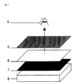
このような偏光板の製造に際しては、予め原料である偏光フィルム1の光の透過率や偏光度あるいはヘイズ等の光学特性を検査し使用してはいるものの、偏光板への製造工程での偏光フィルムへの機械的応力、異物混入あるいは付着等により欠陥が生じる可能性がある。このため最終製品での異物混入や欠陥検査では、図2に示すが如くクロスニコル法(2枚の偏光板5,7を互いに偏光面を直交させ、その間に離型フィルム6の長手方向、幅方向をそれぞれ直交する偏光板の偏光面に合わせて挟まれた状態での透過光を観察する方法)による人間の目視検査を行なっている。実際の偏光板の目視検査においては、正常な検光子7の上に、その偏光面に対して偏光面が直交するように、検査対象の偏光板を、図2のクロスニコル法における偏光子5と離型フィルム6との代わりに重ねて置くと、原理的に、偏光板中の異物混入や欠陥という欠点箇所が輝点として現れるので、目視により欠点が検査できるというものである。
【0005】
しかしながら、従来の偏光板は、離型フィルムとして二軸配向ポリエステルフィルムを用いているためにその光学的異方性が原因で光漏れが生じやすく、正確な目視検査が困難となり、輝点である異物混入や欠陥を見落とす問題が生じている。
【0006】
この問題を解決する方法としては、以下のような方法が提案されている。例えば、特開2000−52417、特開2000−131523または特開平9−258022等では、偏光板検査時において離型フィルムの配向主軸と偏光板の偏光面のなす角度を出来るだけ小さくする方法が開示されている。また、特開平6−3664では、光学異方性の少ない低レターデーションである離型フィルムを用いる方法が開示されている。特開2000−94565では、逆に、高レターデーションを有する離型フィルムを用いる方法が開示されている。その他、マイクロ波を用いた分子配向計の透過光強度パラメータであるMOR値で定義された離型フィルムなどが開示されている。
【0007】
現在、偏光板用の離型フィルムとしては、その透明性、強度、耐熱性および平面性などに優れている点からポリエステルフィルムが一般に用いられている。以下、この偏光板用の離型フィルムとして用いられるためのポリエステルフィルムを、偏光フィルム貼り合わせ用ポリエステルフィルムという。
【0008】
また、偏光フィルム貼り合わせ用としても用いられてきている従来の二軸配向ポリエステルフィルムは、クロスニコル法による偏光板目視検査において、その配向主軸が二枚の偏光板で作られる直交座標からずれると、図2の如く偏光板を観察するときに、複屈折が原因で光透過および光干渉色が生じる。特に、製膜フィルム全幅において、中央部から端部へ移行するほどボーイングが原因でフィルムの配向角のずれ(フィルム長手方向と幅方向でなす直交座標軸と配向主軸となす角度のうち小さい方の角度)が大きくなり、光透過および光干渉色が強くなる。ここでいうボーイングとは、従来からポリエステルフィルム製膜工程において広く用いられているテンター法(フィルムの両端部をレール上を走行するクリップで把持して熱風オーブン等に導き、幅方向延伸および熱処理を行う方法)では、熱処理時にフィルム長手方向に生じる応力差の結果、テンター前にフィルム幅方向にマジックインキで引いた直線が熱処理後には、フィルム長手方向に弓なり状に引き戻された形をして出てくる現象をいう。
【0009】
【発明が解決しようとする課題】
したがって、製膜フィルムを全幅方向にわたって所定のサイズにスリットして偏光フィルム貼り合わせ用の離型フィルムとすると、その中央部では配向角のずれはなく問題は生じないが、その端部へ近づくほど配向角のずれが大きくなるので配向角のずれに起因する問題が生じてしまうので、事実上、フィルム全幅から、光透過等のトラブルのない良品質の離型フィルムを作成することは困難であった。
【0010】
光干渉色は、クロスニコルに挟まれた複屈折体のレターデーションに依存していることが理解されている。レターデーションとは、直線偏光した光が延伸されたポリエステルフィルムなどの複屈折体に入射したとき、振動方向が互いに直交し、しかも速度を異にする偏光波の位相差のことである。このレターデーションと光干渉色の関係は従来からMichel−Levy干渉色図表があることからも知られている。偏光板検査時には、このレターデーションの視角依存性が加わるため、検査人の目に届く透過光は明るく虹色に色付いてしまい、偏光板の異物混入や欠陥を見逃してしまう事態が生じている。すなわち、このレターデーションを改善すれば易検査性の偏光板用離型フィルムが実現する可能性がある。
【0011】
そこで、本発明は、偏光板検査時において、異物混入や欠陥を見落とす原因である光干渉色を改善し、昜検査性に優れた偏光フィルム貼り合わせ用ポリエステルフィルムを提供することを目的とする。
【0012】
【課題を解決するための手段】
本発明は、異物混入や欠陥を見落とす原因と考えられていた多少の光透過があっても、その干渉色を特定することによって上記の目的を達成することを見出すことによってなされたものである。
【0013】
すなわち、本発明は、偏光フィルムと貼り合わせて用いられる偏光フィルム貼り合わせ用ポリエステルフィルムであって、該ポリエステルフィルムを、吸収軸が互いに直交するように配置された2枚の偏光フィルムの間に配置して、白色光の照射により得られる透過光のスペクトルが、色度図においてxが0.35以下かつ、yが0.3以下を満たす領域にある青もしくは紫色系統に色づいており、下記(1)式で示されるレターデーション(Re)が420nm以上660nm以下であることを特徴とするものである。
Re=Δn・d ………式(1)
(ただし、式(1)で、Δnは、波長λ=590nmにおけるフィルム面内方向の複屈折であり、dはフィルムの厚み(nm)である。)
【0014】
【発明の実施の形態】
本発明の偏光フィルム貼り合わせ用ポリエステルフィルムは、上記した要件(請求項1の要件)を満足するので、このフィルムを偏光フィルム貼り合わせ用として用いると、偏光板検査時に白色光を照射することによって得られる透過光が、スペクトルの色度図におけるxが0.35以下かつyが0.3以下を満たす領域にある青もしくは紫色系統に色づいたものとなる。ここで、白色光とは、スペクトル分布が可視光領域のほぼ全体に広がっていて、肉眼で白色に見える光のことである。透過光とは、照射光が被検査側の偏光板及び被検査体のフィルムを透過して出てきた光であり、検査者の視角や検査機器によって認知、測定されるものである。このように、本発明で特定した要件を満足するフィルムならば、このフィルムを、偏向板検査時に、検査側の偏向フィルムと被検査側の偏光フィルムとの間に介在させたときに、透過光を結果的に青もしくは紫色系統の色調にすることができる。本発明のフィルムは、本発明で特定した要件を満足すれば、単層フィルム、積層フィルムのどちらでもよい。
【0015】
本発明の偏光フィルム貼り合わせ用ポリエステルフィルムは、150℃で10分間の熱処理条件で測定されるフィルム長手方向、幅方向の熱収縮率が3%以下であることが好ましい。フィルム長手方向、幅方向の熱収縮率が3%以下であると、偏光フィルムとの接着工程において粘着剤中の溶媒を加熱除去する際に、フィルムの平坦性を保つことが容易となり、偏光フィルム検査時に平坦性不良による検査性の低下を抑えることができる。
【0016】
本発明の偏光フィルム貼り合わせ用ポリエステルフィルムのレターデーション(Re)は、特定範囲内であることが好ましい。このレターデーションとは、下記(1)式で示される物性値である。
【0017】
Re=Δn・d ………式(1)
ここで、Δnは、波長λ=590nmにおけるフィルム面内方向の複屈折、即ち、λ=590nmの光源の光をフイルム面に直角に入射させ、フィルムを透過して出射されてきた透過光を測定することによって求められる複屈折である。また、dはフィルムの厚み(nm)である。
【0018】
本発明のポリエステルフィルムのレターデーション(Re)の好ましい範囲は、420nm以上660nm以下の範囲である。この範囲にすることによって、透過光が青もしくは紫色系統に色づくため、目視検査に優れた偏光フィルム貼り合わせ用ポリエステルフィルムとして使用することができる。この観点からレターデーションが、480nm以上600nm以下であることがより好ましい。その際のポリエステルフィルムの配向角は20度以下が好ましい。
【0019】
本発明のポリエステルフィルムを、偏光フィルムとの貼り合わせに用いる場合は、ポリエステルフィルムに離型処理を施すことが剥離性の点で好ましい。かかる離型処理としては、特に限定されないが、シリコーンコーティング処理が好ましい。中でも、硬化シリコーン樹脂塗膜を形成する処理が好ましく用いられる。この硬化シリコーン樹脂塗膜は、硬化性シリコーン樹脂を含む塗液をフィルムの少なくとも片面に塗布し、乾燥、硬化により成形することができる。
【0020】
本発明のポリエステルフィルムの厚みは、離型フィルムとしての使い勝手のよさの観点から4μm以上60μm以下とすることが好ましく、より好ましくは15μm以上50μm以下である。
【0021】
また、本発明の偏光フィルム貼り合わせポリエステルフィルムは、本発明で特定した物性値を有していれば、単層で構成されたポリエステルフィルムであってもよいし、複数の組成による層から積層されたポリエステルフィルムであってもよい。
【0022】
以下に、本発明の偏光フィルム貼り合わせ用ポリエステルフィルムの製造方法を説明する。
【0023】
本発明におけるポリエステルフィルムに用いられるポリエステルとは、芳香族ジカルボン酸または脂肪族ジカルボン酸とジオールを主たる構成成分とす
るポリエステルである。ここで、芳香族ジカルボン酸として、例えば、テレフタル酸、イソフタル酸、フタル酸、1,4−ナフタレンジカルボン酸、1,5−ナフタレンジカルボン酸、2,6−ナフタレンジカルボン酸、4,4′−ジフェニルジカルボン酸、4,4′−ジフェニルエーテルジカルボン酸、4,4′−ジフェニルスルホンジカルボン酸等を挙げることができる。また、脂肪族ジカルボン酸としては、例えば、アジピン酸、スベリン酸、セバシン酸、ドデカンジオン酸等を挙げることができる。中でも、好ましくはテレフタル酸とイソフタル酸を挙げることができる。これらの酸成分は1種のみ用いてもよく、2種以上併用してもよく、さらには、ヒドロキシ安息香酸等のオキシ酸等を一部共重合してもよい。また、ジオール成分としては、例えば、エチレングリコール、1,2−プロパンジオール、1,3−プロパンジオール、ネオペンチルグリコール、1,3−ブタンジオール、1,4−ブタンジオール、1,5−ペンタンジオール、1,6−ヘキサンジオール、1,2−シクロヘキサンジメタノール、1,3−シクロヘキサンジメタノール、1,4−シクロヘキサンジメタノール、ジエチレングリコール、トリエチレングリコール、ポリアルキレングリコール、2,2−ビス(4−ヒドロキシエトキシフェニル)プロパン等を挙げることができる。中でも、エチレングリコールが好ましく用いられる。これらのジオール成分は1種のみ用いてもよく、2種以上併用してもよい。
【0024】
本発明のポリエステルフィルムに用いられるポリエステルとして好ましくは、ポリエチレンテレフタレート、エチレンテレフタレートとエチレンイソフタレートとの共重合体、ポリブチレンテレフタレートおよびその共重合体、ポリブチレンナフタレートおよびその共重合体、さらにはポリヘキサメチレンテレフタレートおよびその共重合体、ポリヘキサメチレンナフタレートおよびその共重合体等を挙げることができ、特に耐熱性と透明性および機械強度のバランスの点からポリエチレンテレフタレートが好ましく用いられる。
【0025】
本発明におけるポリエステルは、従来公知の方法で製造することができる。例えば、酸成分をジオール成分と直接エステル化反応させた後、この反応の生成物を減圧下で加熱して余剰のジオール成分を除去しつつ重縮合させることによって製造する方法や、酸成分としてジアルキルエステルを用い、これとジオール成分とでエステル交換反応させた後、上記と同様に重縮合させることによって製造する方法等がある。この際、必要に応じて、反応触媒として従来公知のアルカリ金属、アルカリ土類金属、マンガン、コバルト、亜鉛、アンチモン、ゲルマニウムおよびチタン化合物を用いることができる。
【0026】
本発明に於けるポリエステルには、必要に応じてさらに難燃剤、熱安定剤、酸化防止剤、紫外線吸収剤、帯電防止剤、顔料、脂肪酸エステル、ワックス等の有機滑剤あるいはシロキサン等の消泡剤等を配合することができる。
【0027】
さらには必要に応じて、本発明のポリエステルフィルムに易滑性を付与することもできる。易滑性を付与するには、ポリエステルフィルムにおいて従来より公知の技術、例えば、ポリエステルに、クレー、マイカ、酸化チタン、炭酸カルシウム、シリカ、カオリン、アクリル、ポリスチレン、ポリジビニルベンゼンなどからなる無機あるいは有機の微粒子を添加する方法、ポリエステル重合時の触媒が失活して形成される粒子による方法、ポリエステルフィルム製膜中あるいは製膜後にフィルム表面に界面活性剤や離型剤、微粒子を含有したポリマーをコーティングする方法などがある。
【0028】
かかるポリエステルを、上記溶融ポリマーを押出機に供給して、T型口金等を用いてシート状に溶融押出しする。その後、キャスティングドラム上で冷却固化した未延伸フィルムを、ポリエステルのガラス転移点以上の温度で延伸する。延伸方法は、いかなる延伸方法であってもよく、通常、逐次ニ軸延伸方式である長手方向に延伸した後幅方向に延伸する方法、幅方向に延伸した後長手方向に延伸する方法が用いられるが、場合によっては長手方向、幅方向同時に延伸する方法、また長手方向の延伸、幅方向の延伸を複数回組み合わせて行ってもよい。長手方向の延伸倍率は、樹脂の種類、用途などにより異なるが通常、2〜15倍である。特に、ポリエチレンテレフタレートの偏光フィルム貼り合わせ用ポリエステルフィルムの場合、2〜5倍程度である。また、幅方向の延伸倍率は、樹脂の種類、用途などにより異なるが、通常2〜10倍である。特に、ポリエチレンテレフタレートからなるポリエステルフィルムの場合、3〜5倍程度である。次いで、延伸されたフィルムを熱処理する。熱処理温度は、延伸温度より高く結晶融点より低い温度でなされるのが一般的であるが、あまり高くするとボーイングが大きくなりやすいのでポリエチレンテレフタレートである場合は130℃ないし230℃の範囲であることが好ましい。
【0029】
また、ボーイングを低減させる種々の方法を採用することも出来る。フィルムのボーイングを低減させる方法としては、例えば、幅方向延伸後に一旦ポリエステルのガラス転移温度以下に冷却した後熱処理する方法、幅方向延伸後にニップロールを設ける方法、熱処理室を複数のゾーンに分けて段階的に昇温する方法、幅方向に温度分布を設けて熱処理する方法、熱処理室でも幅方向に5〜20%の再延伸を行なう方法などがある。
【0030】
上記のような製膜方法を採用し、その製膜条件である延伸温度、延伸倍率、熱処理温度を適宜調整することによりレターデーション及び、好ましくは熱収縮率を調整する。例えば、請求項3または4記載のレターデーションの範囲を満足させるためには、長手方向の配向を強くしない場合は、その延伸温度は115℃以上1253℃以下が好ましく、延伸倍率は段階的に複数回、延伸し、その全長手方向倍率は、4.0倍以上が好ましい。幅方向においては、延伸温度は100℃程度で延伸倍率は4.0倍以上が好ましい。一方、長手方向の配向を強くする場合は、その延伸温度は85℃以上95℃未満で、その延伸倍率は2.8倍程度が好ましい。幅方向においては、延伸温度は100℃程度で延倍倍率は3.6倍程度が好ましい。熱処理温度は、150℃、10分間の条件で熱収縮率が長手方向、幅方向それぞれが、3%以下を満たす観点から、200℃以上が好ましく、その後熱処理温度以下で幅方向に5%の弛緩熱処理をすることも好ましい。
【0031】
[特性の測定方法]
本発明において、フィルムの特性は以下の方法で測定した。
(1)透過光の色度(x、y)
サンプルは、フイルム幅方向において中央部の位置から、A4大のカットサンプルの長手方向とフィルム長手方向を一致させて切り出した。図2のクロスニコル法に示したように、光源部には、LCDに用いられる白色光源であるバックライト、その上に正常な検光子7と偏光子5の吸収軸面が直交するように配置し、その間にポリエステルフィルム(離型フイルム)6を偏光子5と約45°傾けて挟んだ状態で、偏光子側から分光放射輝度計(ミノルタ(株)製CS−1000)を用いて各波長のスペクトルを測定した。この結果を、備え付けのデータ管理ソフトウエア(ミノルタ製CS−S1w)の演算部で計算することにより色度xおよびyを求めた。
(2)偏光板の目視検査、干渉色
サンプルは、フィルム幅方向における配向角が10度近辺の位置から、A4大のカットサンプルの長手方向とフィルム長手方向を一致させて切り出した。図2のクロスニコル法に示したように、光源部にフジカラーライトボックス100V8W((株)進光社製)を用いて、その上に正常な検光子7と偏光子5の吸収軸面が直交するように配置し、その間にポリエステルフィルムを挟んだ状態で、偏光子側から目視検査を行なった。このとき、観察面側の寸法幅28cm×縦34cmの偏光子の吸収軸とA4カットサンプルのフィルムの長手方向を一致させた。目視検査は輝点として表れる偏光子の50μm以下のサイズを有する異物が確認できるかどうかで以下の基準で評価した。また、干渉色も同時に観察した。
○:異物が輝点として100個以上確認できる。
△:異物が輝度として30個以上100個未満確認できる。
×:異物が輝点として30個未満で、ほとんど確認できない。
【0032】
(3)レターデーション(Re)および配向角
上記したA4カットサンプルのフィルム幅方向の中央部から、長手4.0×幅3.5cmの寸法に切り出したものをサンプルとし、波長λ=590nmにおけるフィルムのレターデーション及び配向角を自動複屈折計(新王子(株)製KOBRA-21ADH)を用いて測定した。
【0033】
(4)熱寸法変化率
サンプルは、フィルムの幅方向の中央部から、長手方向と、幅方向にそれぞれ1cm×16cmで切り出し、サインペンで端から3cmの位置にそれぞれ、マーキングを施した。熱寸法変化率は、ギアオーブン(TABAI社製GHPS−222)で150℃、10分間の条件下で熱処理した前後のフィルム長手方向、幅方向、それぞれのマーキングの間隔を万能投影機(77−7ニコン社製E04)で測長することにより求めた。
【0034】
【実施例】
以下、実施例により本発明をさらに詳細に説明するが、本発明はこれに限られるものではない。
【0035】
[参考例1]通常のポリエチレンテレフタレートを溶融して口金から押出し、25℃のキャスティングドラムで冷却固化した後、86℃に加熱したロールとラジエーションヒーターによってフィルムを加熱して、延伸することにより長手方向に2.8倍延伸し、続いてテンターにて幅方向に100℃で2.96倍延伸し、次いで110℃で1.25倍で幅方向に延伸し、さらに該テンターの後続する熱処理ゾーン4室を段階的に140、180、205、230℃で熱処理し、最後に150℃で5%程度の弛緩熱処理を施すことにより厚み23μmのポリエステルフィルムを得た。
【0036】
[実施例1]通常のポリエチレンテレフタレートを溶融して口金から押出し、25℃のキャスティングドラムで冷却固化した後、予熱温度が116℃で、123℃に加熱したロールとラジエーションヒーターによって長手方向にフィルムを1.03倍、1.64倍、1.1倍、2.59倍と複数回延伸することにより全体で4.8倍延伸し、続いてテンターにて幅方向に110℃で4.1倍延伸し、さらに該テンターの後続する熱処理ゾーンで200℃で熱処理し、110℃で3%の弛緩熱処理を施すことにより厚み14.8μmのポリエステルフィルムを得た。
【0037】
[実施例2]通常のポリエチレンテレフタレートを溶融して口金から押出し、25℃のキャスティングドラムで冷却固化した後、予熱温度が117℃で、123℃に加熱したロールとラジエーションヒーターによって長手方向にフィルムを1.05倍、1.51倍、1.1倍、2.59倍と複数回延伸することにより全体で4.5倍延伸し、続いてテンターにて幅方向に110℃で4.1倍延伸し、さらに長手方向に105℃で1.01倍延伸し、続いて第2テンターの熱処理ゾーンで208℃で熱処理し、110℃で3.5%の弛緩熱処理を施すことにより厚み14.6μmのポリエステルフィルムを得た。上記実施例1〜2の特性を各種評価した結果を表1に示す。
【0038】
[比較例1]
通常のポリエチレンテレフタレートを溶融して口金から押出し、25℃のキャスティングドラムで冷却固化した後、予熱温度が114℃で、118℃に加熱したロールとラジエーションヒーターによって長手方向にフィルムを1.16倍、1.06倍、2.81倍と複数回延伸することにより全体で3.45倍延伸し、続いてテンターにて幅方向に100℃で3.6倍延伸し、さらに、もう一度135℃に加熱したロールによって長手方向に1.56倍延伸し、第2のテンターに導入して熱処理ゾーンで205℃で熱処理し、120℃で3%の弛緩熱処理することによりポリエステルフィルムを得た。
【0039】
[比較例2]
通常のポリエチレンテレフタレートを溶融して口金から押出し、25℃のキャスティングドラムで冷却固化した後、まず90℃に加熱したロールによってフィルムを加熱して長手方向に3.3倍延伸し、続いてテンターにて幅方向に95℃で3.33倍延伸し、さらに該テンターの後続する熱処理ゾーンで230℃で熱処理することにより厚み27μmのポリエステルフィルムを得た。
【0040】
[比較例3]
通常のポリエチレンテレフタレートを溶融して口金から押出し、25℃のキャスティングドラムで冷却固化した後、まず100℃に加熱したロールとラジエーションヒーターによってフィルムを長手方向に2.5倍延伸し、続いてテンターにて幅方向に85℃で3.95倍延伸し、さらに該テンターで140℃で熱処理をし、大気温度で冷却した後、続いて第2テンターの熱処理ゾーン3室を段階的に130、180、220℃まで昇温しながら熱処理することにより厚み30μmのポリエステルフィルムを得た。
【0041】
上記比較例1〜3の特性を各種評価した結果を表1に示す。
【0042】
【表1】

【発明の効果】
本発明のポリエステルフィルムを偏光フィルム貼り合わせ用に用いると、偏光板検査時において、透過光が視覚的に青もしくは青紫に感じることができるので、この色調の透過光背景色が偏光板の異物や欠点を浮き出させるように作用し、検査性が向上するものである。このように、本発明によると、異物混入や欠陥を見落とす原因である光干渉色を改善し、昜検査性に優れた偏光フィルム貼り合わせ用ポリエステルフィルムを得ることができるのである。
【図面の簡単な説明】
【図1】 偏光板の構成を例示する図である。
【図2】 クロスニコル法による目視検査の方法を説明する図である。
【符号の説明】
1:偏光フィルム
2:表面保護フィルム
3:粘着剤層
4:離型フィルム
5:偏光子
6:ポリエステルフィルム
7:検光子
8:白色光源
9:検査する人の目の位置[0001]
BACKGROUND OF THE INVENTION
The present invention relates to a polyester film for laminating a polarizing film, and more specifically, the present invention makes it possible to easily find foreign matters and defects by visual inspection of a polarizing plate, a retardation polarizing plate or a retardation plate. The present invention relates to a polarizing film laminating polyester film suitable for use as a release film or the like.
[0002]
[Prior art]
In recent years, the importance of a liquid crystal display (Liquid Crystal Display) having advantages of a thin, light weight, low power consumption, and high image quality as compared with a conventional CRT (Cathode Ray Tube) has been rapidly increasing. In particular, in the large screen TFT (Thin Film Transistor) method and STN (Super Twisted Nematic) method, the defective product generation rate is high, and improvement in cost is urgently required. Polarizers, retardation polarizers, or retardation plates are indispensable components for making the transmitted light of the LCD brighter and darker and for changing the hue. However, it is also important to maintain stable quality for these components. ing.
[0003]
The polarizing plate is usually composed of a polarizing
[0004]
In manufacturing such a polarizing plate, although optical properties such as light transmittance, polarization degree, and haze of the polarizing
[0005]
However, since a conventional polarizing plate uses a biaxially oriented polyester film as a release film, light leakage is likely to occur due to its optical anisotropy, making accurate visual inspection difficult and a bright spot. There is a problem of overlooking foreign matter and defects.
[0006]
As methods for solving this problem, the following methods have been proposed. For example, JP-A-2000-52417, JP-A-2000-131523, or JP-A-9-258022 discloses a method for minimizing the angle between the orientation axis of the release film and the polarization plane of the polarizing plate during polarizing plate inspection. Has been. Japanese Patent Laid-Open No. 6-3664 discloses a method using a release film having a low retardation with little optical anisotropy. In contrast, Japanese Patent Laid-Open No. 2000-94565 discloses a method using a release film having a high retardation. In addition, a release film defined by a MOR value that is a transmitted light intensity parameter of a molecular orientation meter using a microwave is disclosed.
[0007]
Currently, polyester films are generally used as release films for polarizing plates because of their excellent transparency, strength, heat resistance, flatness, and the like. Hereinafter, the polyester film to be used as the release film for the polarizing plate is referred to as a polarizing film laminating polyester film.
[0008]
In addition, the conventional biaxially oriented polyester film that has also been used for polarizing film laminating is that when the orientation main axis is deviated from the orthogonal coordinates formed by two polarizing plates in the visual inspection of the polarizing plate by the crossed Nicols method. When the polarizing plate is observed as shown in FIG. 2, light transmission and light interference colors are generated due to birefringence. In particular, in the full width of the film-forming film, the deviation of the orientation angle of the film due to bowing as it moves from the center to the end (the smaller angle of the angle between the orthogonal coordinate axis formed in the film longitudinal direction and the width direction and the orientation main axis) ) Increases, and light transmission and light interference colors become stronger. Boeing here refers to the tenter method that has been widely used in the polyester film forming process from the past (gripping both ends of the film with clips that run on the rail, leading to a hot air oven, etc. Method), as a result of the stress difference that occurs in the longitudinal direction of the film during the heat treatment, the straight line drawn with the magic ink in the width direction of the film before the tenter is drawn back into a bow shape in the longitudinal direction of the film after the heat treatment. The phenomenon that comes.
[0009]
[Problems to be solved by the invention]
Therefore, when the film-forming film is slit to a predetermined size over the entire width direction to form a release film for laminating a polarizing film, there is no problem in the orientation angle and no problem occurs at the center, but the closer it is to the end Since the displacement of the orientation angle becomes large, problems due to the displacement of the orientation angle will occur, so it is practically difficult to produce a good quality release film free from troubles such as light transmission from the entire width of the film. It was.
[0010]
It is understood that the light interference color depends on the retardation of the birefringent body sandwiched between crossed Nicols. Retardation is a phase difference of polarized waves whose vibration directions are orthogonal to each other and have different speeds when linearly polarized light enters a birefringent body such as a stretched polyester film. This relationship between retardation and light interference color is also known from the fact that there is a Michel-Levy interference color chart. At the time of polarizing plate inspection, the retardation depends on the viewing angle, so that the transmitted light reaching the eyes of the inspector is brightly colored in rainbow colors, and there is a situation in which foreign matters and defects in the polarizing plate are overlooked. That is, if this retardation is improved, an easily inspectable release film for polarizing plates may be realized.
[0011]
Therefore, an object of the present invention is to provide a polyester film for laminating a polarizing film that improves light interference color, which is a cause of overlooking foreign matters and defects during polarizing plate inspection, and is excellent in wrinkle inspection.
[0012]
[Means for Solving the Problems]
The present invention has been made by finding that the above object can be achieved by specifying the interference color even if there is some light transmission that was thought to be a cause of overlooking foreign matter contamination and defects.
[0013]
That is, the present invention is a polyester film for laminating a polarizing film that is used by laminating with a polarizing film, and the polyester film is disposed between two polarizing films that are disposed so that their absorption axes are orthogonal to each other. and, the spectrum of transmitted light obtained by the irradiation of the white light, and x is 0.35 or less in the chromaticity diagram, and colored blue or violet system in the region where y satisfies 0.3 or less, the following ( 1) retardation (Re) represented by the formula is characterized in der Rukoto than 660nm or less 420 nm.
Re = Δn · d Equation (1)
(In the formula (1), Δn is birefringence in the in-plane direction of the film at a wavelength λ = 590 nm, and d is the thickness (nm) of the film.)
[0014]
DETAILED DESCRIPTION OF THE INVENTION
Since the polyester film for laminating a polarizing film of the present invention satisfies the above-mentioned requirements (requirements of claim 1), when this film is used for laminating a polarizing film, it is irradiated with white light during polarizing plate inspection. The obtained transmitted light is colored blue or purple in a region where x is 0.35 or less and y is 0.3 or less in the spectral chromaticity diagram. Here, the white light is light that has a spectral distribution that extends over almost the entire visible light region and appears white to the naked eye. The transmitted light is light emitted from the irradiated light that has passed through the inspected polarizing plate and the film of the object to be inspected, and is recognized and measured by the inspector's viewing angle and inspection equipment. Thus, if the film satisfies the requirements specified in the present invention, the transmitted light is transmitted when the film is interposed between the inspection-side deflection film and the inspection-side polarizing film during the deflection plate inspection. As a result, the color tone of blue or purple can be obtained. The film of the present invention may be either a single layer film or a laminated film as long as the requirements specified in the present invention are satisfied.
[0015]
The polyester film for laminating a polarizing film of the present invention preferably has a thermal shrinkage rate of 3% or less in the film longitudinal direction and width direction measured under heat treatment conditions at 150 ° C. for 10 minutes. When the heat shrinkage rate in the longitudinal direction and the width direction of the film is 3% or less, it becomes easy to maintain the flatness of the film when the solvent in the pressure-sensitive adhesive is removed by heating in the bonding step with the polarizing film. It is possible to suppress a decrease in inspection property due to poor flatness during inspection.
[0016]
The retardation (Re) of the polyester film for laminating a polarizing film of the present invention is preferably within a specific range. This retardation is a physical property value represented by the following formula (1).
[0017]
Re = Δn · d Equation (1)
Here, Δn is the birefringence in the in-plane direction of the film at a wavelength of λ = 590 nm, that is, the transmitted light emitted through the film is incident on the film surface at right angles to the light of λ = 590 nm. The birefringence required by D is the thickness (nm) of the film.
[0018]
A preferred range of the retardation of the polyester film of the present invention (Re) is 660nm or less of the range above 420 nm. By setting it as this range, since transmitted light colors blue or purple, it can be used as a polarizing film laminating polyester film excellent in visual inspection. Retardation from this viewpoint, it Gayo more preferable at 480nm or 600nm or less. Orientation angle is arbitrary preferred is 2 0 degrees or less of the polyester film at that time.
[0019]
When using the polyester film of this invention for bonding with a polarizing film, it is preferable at a peelable point to perform a mold release process to a polyester film. Such a release treatment is not particularly limited, but a silicone coating treatment is preferable. Among these, a treatment for forming a cured silicone resin coating film is preferably used. This cured silicone resin coating film can be formed by applying a coating liquid containing a curable silicone resin to at least one surface of a film, followed by drying and curing.
[0020]
The thickness of the polyester film of the present invention is preferably 4 μm or more and 60 μm or less, more preferably 15 μm or more and 50 μm or less from the viewpoint of ease of use as a release film.
[0021]
Further, the polarizing film-laminated polyester film of the present invention may be a polyester film composed of a single layer as long as it has the physical property values specified in the present invention, and is laminated from layers having a plurality of compositions. Polyester film may be used.
[0022]
Below, the manufacturing method of the polyester film for polarizing film bonding of this invention is demonstrated.
[0023]
The polyester used for the polyester film in the present invention is a polyester mainly composed of aromatic dicarboxylic acid or aliphatic dicarboxylic acid and diol. Here, as the aromatic dicarboxylic acid, for example, terephthalic acid, isophthalic acid, phthalic acid, 1,4-naphthalenedicarboxylic acid, 1,5-naphthalenedicarboxylic acid, 2,6-naphthalenedicarboxylic acid, 4,4′-diphenyl Dicarboxylic acid, 4,4'-diphenyl ether dicarboxylic acid, 4,4'-diphenylsulfone dicarboxylic acid and the like can be mentioned. Examples of the aliphatic dicarboxylic acid include adipic acid, suberic acid, sebacic acid, dodecanedioic acid and the like. Of these, terephthalic acid and isophthalic acid are preferable. These acid components may be used alone or in combination of two or more thereof, and further may be partially copolymerized with oxyacids such as hydroxybenzoic acid. Examples of the diol component include ethylene glycol, 1,2-propanediol, 1,3-propanediol, neopentyl glycol, 1,3-butanediol, 1,4-butanediol, and 1,5-pentanediol. 1,6-hexanediol, 1,2-cyclohexanedimethanol, 1,3-cyclohexanedimethanol, 1,4-cyclohexanedimethanol, diethylene glycol, triethylene glycol, polyalkylene glycol, 2,2-bis (4- Hydroxyethoxyphenyl) propane and the like can be mentioned. Of these, ethylene glycol is preferably used. These diol components may be used alone or in combination of two or more.
[0024]
The polyester used in the polyester film of the present invention is preferably polyethylene terephthalate, a copolymer of ethylene terephthalate and ethylene isophthalate, polybutylene terephthalate and its copolymer, polybutylene naphthalate and its copolymer, and Examples include hexamethylene terephthalate and copolymers thereof, polyhexamethylene naphthalate and copolymers thereof, and polyethylene terephthalate is particularly preferably used from the viewpoint of balance between heat resistance, transparency, and mechanical strength.
[0025]
The polyester in the present invention can be produced by a conventionally known method. For example, a method in which an acid component is directly esterified with a diol component, and then the product of this reaction is heated under reduced pressure to perform polycondensation while removing excess diol component, or a dialkyl as an acid component There is a method in which an ester is used for ester exchange reaction between this and a diol component, followed by polycondensation in the same manner as described above. At this time, conventionally known alkali metals, alkaline earth metals, manganese, cobalt, zinc, antimony, germanium, and titanium compounds can be used as a reaction catalyst, if necessary.
[0026]
The polyester in the present invention may further include a flame retardant, a heat stabilizer, an antioxidant, an ultraviolet absorber, an antistatic agent, an organic lubricant such as a pigment, a fatty acid ester and a wax, or an antifoaming agent such as siloxane, if necessary. Etc. can be blended.
[0027]
Furthermore, if necessary, easy slipperiness can be imparted to the polyester film of the present invention. In order to impart slipperiness, conventionally known techniques for polyester films, for example, inorganic or organic polyesters such as clay, mica, titanium oxide, calcium carbonate, silica, kaolin, acrylic, polystyrene, polydivinylbenzene, etc. A method of adding fine particles, a method using particles formed by deactivation of a catalyst during polyester polymerization, a surfactant, a release agent, or a polymer containing fine particles on the film surface during or after polyester film formation. There are coating methods.
[0028]
The polyester is melt-extruded into a sheet using a T-type die or the like by supplying the molten polymer to an extruder. Thereafter, the unstretched film cooled and solidified on the casting drum is stretched at a temperature equal to or higher than the glass transition point of the polyester. The stretching method may be any stretching method, and a method of stretching in the longitudinal direction and then stretching in the width direction, which is a sequential biaxial stretching method, and a method of stretching in the width direction and then stretching in the longitudinal direction are used. However, in some cases, the method of stretching in the longitudinal direction and the width direction at the same time, or stretching in the longitudinal direction and stretching in the width direction may be combined multiple times. The draw ratio in the longitudinal direction is usually 2 to 15 times, although it varies depending on the type of resin and the application. In particular, in the case of a polyester film for laminating a polarizing film of polyethylene terephthalate, it is about 2 to 5 times. Moreover, although the draw ratio of the width direction changes with kinds, uses, etc. of resin, it is 2-10 times normally. In particular, in the case of a polyester film made of polyethylene terephthalate, it is about 3 to 5 times. Next, the stretched film is heat-treated. The heat treatment temperature is generally higher than the stretching temperature and lower than the crystal melting point. However, if the temperature is too high, bowing tends to increase. Therefore, in the case of polyethylene terephthalate, it may be in the range of 130 ° C to 230 ° C. preferable.
[0029]
Various methods for reducing the bowing can also be employed. Examples of a method for reducing the bowing of the film include, for example, a method in which the film is once cooled to a temperature equal to or lower than the glass transition temperature of the polyester after stretching in the width direction, a method in which a nip roll is provided after stretching in the width direction, and the heat treatment chamber is divided into a plurality of zones. There are a method of increasing the temperature in a certain manner, a method of performing a heat treatment by providing a temperature distribution in the width direction, a method of performing re-stretching by 5 to 20% in the width direction in a heat treatment chamber, and the like.
[0030]
The film forming method as described above is employed, and the retardation and preferably the heat shrinkage rate are adjusted by appropriately adjusting the film forming conditions such as the stretching temperature, the stretching ratio, and the heat treatment temperature. For example, in order to satisfy the retardation range according to
[0031]
[Measurement method of characteristics]
In the present invention, the film properties were measured by the following method.
(1) Chromaticity (x, y) of transmitted light
The sample was cut out from the central position in the film width direction so that the longitudinal direction of the A4 large cut sample coincided with the longitudinal direction of the film. As shown in the crossed Nicols method of FIG. 2, the light source unit is arranged so that the backlight, which is a white light source used in the LCD, and the
(2) The visual inspection of the polarizing plate and the interference color sample were cut out by aligning the longitudinal direction of the A4 large cut sample with the film longitudinal direction from the position where the orientation angle in the film width direction was around 10 degrees. As shown in the crossed Nicols method of FIG. 2, a Fuji color light box 100V8W (manufactured by Shinko Co., Ltd.) is used as the light source, and the
○: 100 or more foreign matters can be confirmed as bright spots.
(Triangle | delta): 30 or less and less than 100 foreign substances can be confirmed as a brightness | luminance.
X: The number of foreign matters is less than 30 as bright spots, and almost no confirmation is possible.
[0032]
(3) Retardation (Re) and orientation angle A film cut at a wavelength of λ = 590 nm is used as a sample obtained by cutting the above A4 cut sample from the center in the film width direction into a length of 4.0 × width of 3.5 cm. The orientation angle was measured using an automatic birefringence meter (KOBRA-21ADH manufactured by Shin-Oji Co., Ltd.).
[0033]
(4) The thermal dimensional change rate sample was cut out at 1 cm × 16 cm in the longitudinal direction and in the width direction from the center in the width direction of the film, respectively, and marked at a
[0034]
【Example】
EXAMPLES Hereinafter, although an Example demonstrates this invention further in detail, this invention is not limited to this.
[0035]
[ Reference Example 1] Normal polyethylene terephthalate is melted and extruded from a die, cooled and solidified by a casting drum at 25 ° C, and then the film is heated by a roll heated to 86 ° C and a radiation heater and stretched in the longitudinal direction. , And then stretched in the width direction at 100 ° C. by 2.96 times, then stretched in the width direction at 110 ° C. and 1.25 times, and further followed by the heat treatment zone 4 of the tenter. The chamber was heat-treated stepwise at 140, 180, 205, and 230 ° C., and finally a relaxation heat treatment of about 5% was performed at 150 ° C. to obtain a polyester film having a thickness of 23 μm.
[0036]
[Example 1 ] Normal polyethylene terephthalate was melted and extruded from a die, cooled and solidified with a casting drum at 25 ° C, and a film was formed in the longitudinal direction by a roll heated to 123 ° C and a radiation heater at a preheating temperature of 116 ° C. 1.03 times, 1.64 times, 1.1 times, 2.59 times, and a total of 4.8 times by stretching several times, followed by 4.1 times at 110 ° C in the width direction with a tenter The polyester film was stretched and further heat treated at 200 ° C. in a heat treatment zone subsequent to the tenter and subjected to 3% relaxation heat treatment at 110 ° C. to obtain a polyester film having a thickness of 14.8 μm.
[0037]
[Example 2 ] Normal polyethylene terephthalate was melted and extruded from a die, cooled and solidified with a casting drum at 25 ° C, and then a preheat temperature of 117 ° C and a film heated in the longitudinal direction by a roll heated to 123 ° C and a radiation heater. 1.05 times, 1.51 times, 1.1 times, and 2.59 times are stretched 4.5 times as a whole, followed by a tenter and 4.1 times at 110 ° C in the width direction. Stretched, further stretched 1.01 times at 105 ° C in the longitudinal direction, subsequently heat treated at 208 ° C in the heat treatment zone of the second tenter, and subjected to 3.5% relaxation heat treatment at 110 ° C to give a thickness of 14.6 µm A polyester film was obtained. Table 1 shows the results of various evaluations of the characteristics of Examples 1-2 .
[0038]
[Comparative Example 1]
After melting ordinary polyethylene terephthalate and extruding it from the die, cooling and solidifying with a casting drum at 25 ° C., the preheating temperature is 114 ° C., and the film is 1.16 times in the longitudinal direction by a roll heated to 118 ° C. and a radiation heater, By stretching several times to 1.06 times and 2.81 times, the whole stretches 3.45 times, then stretches 3.6 times at 100 ° C in the width direction with a tenter, and further heated to 135 ° C The polyester film was obtained by stretching 1.56 times in the longitudinal direction with the rolled roll, introducing into the second tenter, heat-treating at 205 ° C. in the heat treatment zone, and 3% relaxation heat treatment at 120 ° C.
[0039]
[Comparative Example 2]
After melting ordinary polyethylene terephthalate and extruding it from the die, cooling and solidifying with a casting drum at 25 ° C, the film is first heated by a roll heated to 90 ° C and stretched 3.3 times in the longitudinal direction. The film was stretched 3.33 times at 95 ° C. in the width direction, and further heat treated at 230 ° C. in the heat treatment zone following the tenter to obtain a 27 μm thick polyester film.
[0040]
[Comparative Example 3]
Normal polyethylene terephthalate is melted and extruded from the die, cooled and solidified with a casting drum at 25 ° C., then the film is first stretched 2.5 times in the longitudinal direction by a roll heated to 100 ° C. and a radiation heater, and then the tenter is used. Then, the film was stretched 3.95 times in the width direction at 85 ° C., further heat-treated at 140 ° C. with the tenter and cooled at the atmospheric temperature, and then the
[0041]
Table 1 shows the results of various evaluations of the characteristics of Comparative Examples 1 to 3.
[0042]
[Table 1]
【The invention's effect】
When the polyester film of the present invention is used for polarizing film bonding, the transmitted light can visually feel blue or bluish purple at the time of polarizing plate inspection. It works to raise the defects and improves the inspectability. As described above, according to the present invention, it is possible to obtain a polyester film for polarizing film laminating which improves the light interference color which is a cause of overlooking foreign matters and defects and is excellent in wrinkle inspection.
[Brief description of the drawings]
FIG. 1 is a diagram illustrating a configuration of a polarizing plate.
FIG. 2 is a diagram for explaining a visual inspection method using a crossed Nicols method.
[Explanation of symbols]
1: Polarizing film 2: Surface protective film 3: Adhesive layer 4: Release film 5: Polarizer 6: Polyester film 7: Analyzer 8: White light source 9: Position of human eye to be inspected
Claims (5)
Re=Δn・d ………式(1)
(ただし、式(1)で、Δnは、波長λ=590nmにおけるフィルム面内方向の複屈折であり、dはフィルムの厚み(nm)である。) A polyester film for laminating a polarizing film to be used by laminating with a polarizing film, the polyester film being disposed between two polarizing films disposed so that the absorption axes are orthogonal to each other, The spectrum of transmitted light obtained by irradiation is colored blue or purple in the region where x is 0.35 or less and y is 0.3 or less in the chromaticity diagram, and is represented by the following formula (1). polyester film for the retardation (Re) is bonded to the polarizing film characterized der Rukoto more than 660nm or less 420nm.
Re = Δn · d Equation (1)
(In the formula (1), Δn is birefringence in the in-plane direction of the film at a wavelength λ = 590 nm, and d is the thickness (nm) of the film.)
Priority Applications (1)
| Application Number | Priority Date | Filing Date | Title |
|---|---|---|---|
| JP2000388487A JP4635335B2 (en) | 2000-12-21 | 2000-12-21 | Polyester film for polarizing film lamination |
Applications Claiming Priority (1)
| Application Number | Priority Date | Filing Date | Title |
|---|---|---|---|
| JP2000388487A JP4635335B2 (en) | 2000-12-21 | 2000-12-21 | Polyester film for polarizing film lamination |
Publications (2)
| Publication Number | Publication Date |
|---|---|
| JP2002189125A JP2002189125A (en) | 2002-07-05 |
| JP4635335B2 true JP4635335B2 (en) | 2011-02-23 |
Family
ID=18855205
Family Applications (1)
| Application Number | Title | Priority Date | Filing Date |
|---|---|---|---|
| JP2000388487A Expired - Fee Related JP4635335B2 (en) | 2000-12-21 | 2000-12-21 | Polyester film for polarizing film lamination |
Country Status (1)
| Country | Link |
|---|---|
| JP (1) | JP4635335B2 (en) |
Families Citing this family (10)
| Publication number | Priority date | Publication date | Assignee | Title |
|---|---|---|---|---|
| JP4528689B2 (en) * | 2004-08-06 | 2010-08-18 | 株式会社巴川製紙所 | Optical film inspection member and optical film inspection method |
| JP4918944B2 (en) * | 2009-10-09 | 2012-04-18 | 東洋紡績株式会社 | Polarizing plate using biaxially oriented polyethylene terephthalate film |
| JP5844027B2 (en) * | 2009-11-18 | 2016-01-13 | 東洋紡株式会社 | Polyethylene terephthalate film for protecting by sticking to the surface of polarizing plate or retardation plate |
| JP2011252048A (en) * | 2010-06-01 | 2011-12-15 | Mitsubishi Plastics Inc | Polyester film for protecting polarizing plate |
| JP2011034113A (en) * | 2010-11-05 | 2011-02-17 | Sharp Corp | Liquid crystal display device |
| US9817154B2 (en) | 2012-08-06 | 2017-11-14 | Mitsubishi Chemical Corporation | Acrylic resin film and retroreflective sheet |
| WO2016147767A1 (en) * | 2015-03-13 | 2016-09-22 | 東レ株式会社 | Polyester film for optical use and polarizing plate using same |
| JP5991416B2 (en) * | 2015-08-10 | 2016-09-14 | 東洋紡株式会社 | Polarizer |
| JP6264408B2 (en) * | 2016-08-10 | 2018-01-24 | 東洋紡株式会社 | Polarizer |
| CN107064155A (en) * | 2017-03-10 | 2017-08-18 | 深圳中兴创新材料技术有限公司 | The detection method and device of a kind of lithium ion battery separator |
Family Cites Families (5)
| Publication number | Priority date | Publication date | Assignee | Title |
|---|---|---|---|---|
| JP3520347B2 (en) * | 1992-06-19 | 2004-04-19 | 東洋紡績株式会社 | Release film for polarizing plate |
| JP3403859B2 (en) * | 1995-04-26 | 2003-05-06 | 帝人株式会社 | Release film |
| JP3737564B2 (en) * | 1996-06-04 | 2006-01-18 | 帝人株式会社 | Release film |
| JP2000171636A (en) * | 1998-09-28 | 2000-06-23 | Konica Corp | Polarizing plate |
| JP2000206333A (en) * | 1999-01-18 | 2000-07-28 | Okura Ind Co Ltd | Polarizing plate and elliptically polarizing plate |
-
2000
- 2000-12-21 JP JP2000388487A patent/JP4635335B2/en not_active Expired - Fee Related
Also Published As
| Publication number | Publication date |
|---|---|
| JP2002189125A (en) | 2002-07-05 |
Similar Documents
| Publication | Publication Date | Title |
|---|---|---|
| JP4644916B2 (en) | Polyester film for polarizing film lamination | |
| JP5177769B2 (en) | Biaxially stretched polyester film for release film and release film using the same | |
| JP4374859B2 (en) | Support film for polarizing film and polarizing plate | |
| JP3403859B2 (en) | Release film | |
| TWI649591B (en) | Protective film for polarizing member, polarizing plate including the same, and display device having the same | |
| JP4691842B2 (en) | Polyester film for polarizing film lamination | |
| TWI744551B (en) | Polarizer protective film, polarizer and liquid crystal display device | |
| JP4639435B2 (en) | Biaxially oriented polyester film for release film | |
| JP2009012254A (en) | Release film | |
| JP4635335B2 (en) | Polyester film for polarizing film lamination | |
| JPH09314782A (en) | Release film | |
| JP2003231214A (en) | Release film | |
| JP2000162419A (en) | Phase difference film | |
| JP2004042318A (en) | Biaxially oriented polyester film | |
| JP2001329078A (en) | Release film | |
| JP7024934B1 (en) | Polyester film for protector protector, polarizing plate and liquid crystal display device | |
| JP5249107B2 (en) | Biaxially oriented polyester film for optics | |
| JP2002210879A (en) | Release film | |
| JP4724955B2 (en) | Method for producing polyester film and polyester film | |
| TW202030239A (en) | Polyester film and polarizing plate containing the polyester film | |
| JP5844027B2 (en) | Polyethylene terephthalate film for protecting by sticking to the surface of polarizing plate or retardation plate | |
| JP2003327719A (en) | Polyester film for release film | |
| JP4710125B2 (en) | Biaxially oriented polyester film and method for producing the same | |
| JP2001353775A (en) | Method for producing polyester film | |
| JP2010237378A (en) | Biaxially oriented laminated polyester film for optics |
Legal Events
| Date | Code | Title | Description |
|---|---|---|---|
| A621 | Written request for application examination |
Free format text: JAPANESE INTERMEDIATE CODE: A621 Effective date: 20071214 |
|
| A977 | Report on retrieval |
Free format text: JAPANESE INTERMEDIATE CODE: A971007 Effective date: 20100223 |
|
| A131 | Notification of reasons for refusal |
Free format text: JAPANESE INTERMEDIATE CODE: A131 Effective date: 20100309 |
|
| A521 | Request for written amendment filed |
Free format text: JAPANESE INTERMEDIATE CODE: A523 Effective date: 20100428 |
|
| TRDD | Decision of grant or rejection written | ||
| A01 | Written decision to grant a patent or to grant a registration (utility model) |
Free format text: JAPANESE INTERMEDIATE CODE: A01 Effective date: 20101026 |
|
| A01 | Written decision to grant a patent or to grant a registration (utility model) |
Free format text: JAPANESE INTERMEDIATE CODE: A01 |
|
| A61 | First payment of annual fees (during grant procedure) |
Free format text: JAPANESE INTERMEDIATE CODE: A61 Effective date: 20101108 |
|
| FPAY | Renewal fee payment (event date is renewal date of database) |
Free format text: PAYMENT UNTIL: 20131203 Year of fee payment: 3 |
|
| R151 | Written notification of patent or utility model registration |
Ref document number: 4635335 Country of ref document: JP Free format text: JAPANESE INTERMEDIATE CODE: R151 |
|
| FPAY | Renewal fee payment (event date is renewal date of database) |
Free format text: PAYMENT UNTIL: 20131203 Year of fee payment: 3 |
|
| LAPS | Cancellation because of no payment of annual fees |