JP4635325B2 - Control valve type lead acid battery - Google Patents
Control valve type lead acid battery Download PDFInfo
- Publication number
- JP4635325B2 JP4635325B2 JP2000331789A JP2000331789A JP4635325B2 JP 4635325 B2 JP4635325 B2 JP 4635325B2 JP 2000331789 A JP2000331789 A JP 2000331789A JP 2000331789 A JP2000331789 A JP 2000331789A JP 4635325 B2 JP4635325 B2 JP 4635325B2
- Authority
- JP
- Japan
- Prior art keywords
- active material
- positive electrode
- control valve
- valve type
- electrode active
- Prior art date
- Legal status (The legal status is an assumption and is not a legal conclusion. Google has not performed a legal analysis and makes no representation as to the accuracy of the status listed.)
- Expired - Lifetime
Links
Classifications
-
- Y—GENERAL TAGGING OF NEW TECHNOLOGICAL DEVELOPMENTS; GENERAL TAGGING OF CROSS-SECTIONAL TECHNOLOGIES SPANNING OVER SEVERAL SECTIONS OF THE IPC; TECHNICAL SUBJECTS COVERED BY FORMER USPC CROSS-REFERENCE ART COLLECTIONS [XRACs] AND DIGESTS
- Y02—TECHNOLOGIES OR APPLICATIONS FOR MITIGATION OR ADAPTATION AGAINST CLIMATE CHANGE
- Y02E—REDUCTION OF GREENHOUSE GAS [GHG] EMISSIONS, RELATED TO ENERGY GENERATION, TRANSMISSION OR DISTRIBUTION
- Y02E60/00—Enabling technologies; Technologies with a potential or indirect contribution to GHG emissions mitigation
- Y02E60/10—Energy storage using batteries
Landscapes
- Secondary Cells (AREA)
- Battery Electrode And Active Subsutance (AREA)
Description
【0001】
【発明が属する技術分野】
本発明は、制御弁式鉛蓄電池に関するものである。
【0002】
【従来の技術】
制御弁式鉛蓄電池は安価で信頼性が高いという特徴を有するため、無停電電源装置用の電源として広く使用されている。しかし、一般的に鉛蓄電池は、他の電池に比べて、集電体や活物質として用いられている鉛の密度が高く、質量エネルギー密度が他の電池に比べて低い値となっている。
【0003】
なお、制御弁式鉛蓄電池には、一般的に正極板及び負極板として鉛合金を用いた格子体に、ペースト状活物質を塗着して作製するペースト式電極板が使用されている。
【0004】
制御弁式鉛蓄電池の質量エネルギー密度を高くするには、正極板に使用されている正極活物質の利用率を向上させる手法が有効である。なお、正極活物質の利用率を向上させるためには、前記正極活物質を多孔質化する手段が用いられている。
【0005】
すなわち、前記正極活物質を多孔質化することによって、多量の電解液を活物質中に含むようにすることができ、その結果、電極の反応面積が増加するため、正極活物質の利用率が向上するものである。
【0006】
なお、正極活物質を多孔質化にする手段としては、鉛酸化物の粉末を主成分とし、水分量を増やしたペースト状活物質を作製した後、該ペースト状活物質を鉛合金からなる格子体に塗着した後、熟成・乾燥して作製する方法が一般的に用いられている。
【0007】
【発明が解決しようとする課題】
しかしながら、ペースト状活物質の水分量が多すぎると、ペースト状活物質が軟らかくなりすぎて、格子体に充填しにくいという問題点がある。一方、水分量が多いペースト状活物質を用いて作製した正極板は、正極活物質を構成する粒子間の密着強度が低下する。したがって、正極活物質が格子体から脱落しやすく、短期間に寿命となるという問題点がある。
【0008】
本発明の目的は、正極活物質の利用率が高く、長寿命な制御弁式据置鉛蓄電池を提供することである。
【0009】
【課題を解決するための手段】
上記した課題を解決するために、第一の発明は、正極活物質中に炭素粉末、導電性繊維を用いる制御弁式鉛蓄電池において、前記正極活物質中にリン酸が含有されていることを特徴とし、第二の発明は、前記リン酸は、前記正極活物質中に0.1〜1質量%含有されていることを特徴とし、第三の発明は、前記炭素粉末は、平均粒子径が100μm以上の鱗片状のグラファイトであることを特徴とし、第四の発明は、前記導電性繊維は、炭素繊維、鉛繊維、錫繊維のいずれかであることを特徴とするものである。
【0010】
【発明の実施の形態】
1.正極板の作製・試験条件
従来から使用している、一酸化鉛を主成分とする鉛粉、鉛丹、後述する各種粒径の鱗片状グラファイト、各種導電性繊維繊維、水、希硫酸及び樹脂繊維を原材料として用い、これらを従来の手法で混練して正極用ペースト状活物質を作製した。なお、正極用ペースト状活物質を、格子体への塗着が可能な硬さになるように水分量を調節した。
【0011】
鱗片状グラファイトとして、平均粒子径が10〜500μm(日本黒鉛製)のものを用いた。導電性繊維繊維として、平均直径が約10μmの炭素繊維(東レ製)、平均直径が約20μmの鉛繊維、平均直径が約20μm酸化錫繊維を用いた。
【0012】
後述するように、本発明では、これらの原材料に後述する所定量のオルトリン酸(H3PO4)の85質量%水溶液を加えて、混練して正極用のペースト状活物質を作成した。
【0013】
作製したペースト状活物質を用いて、通常の手法で正極板を作成した。すなわち、高さが115mm、幅が60mm、厚みが4.0mmの鉛−カルシウム−錫合金製の格子体に、前記ペースト状活物質を充填する。その後、温度が35〜45℃、相対湿度が90%以上の雰囲気中で熟成をした後、乾燥してペースト式正極板を得た。
【0014】
2.制御弁式鉛蓄電池の作製条件
上記した手法で作製したペースト式正極板と、従来から使用していた高さが115mm、幅が60mm、厚みが2.0mmの、鉛−カルシウム−錫合金製の格子体を用いたペースト式負極板を使用した。
【0015】
そして、従来の手法を用い、リテーナを介して前記ペースト式正極板が3枚、ペースト式負極板が4枚を使用し、溶接して極板群を作成し、該極板群の電槽への挿入時の群加圧が20kPaになるように、厚みが1mmのポリプロピレン製のスペーサを前記極板群の両側面に当接した状態で組み立てて制御弁式鉛蓄電池を作製する。
【0016】
そして、希硫酸電解液を注液した状態で電槽化成をして、20時間率の放電容量が15Ah、公称電圧が2Vの制御弁式鉛蓄電池を作製した。
【0017】
3.制御弁式鉛蓄電池の試験条件
上記した本発明品及び後述する各種の比較例の制御弁式鉛蓄電池について、以下の条件で初期の放電時間及び加速試験後の放電時間を測定した。
【0018】
作成した制御弁式鉛蓄電池は25℃、2.4Aの定電流で、終止電圧1.7V/セルまで放電することによって、それらの放電容量を測定する。そして、正極活物質の充填量と、理論容量とから正極活物質利用率を比較した。
【0019】
初期の放電試験をした後、25°Cの恒温槽中、0.45Aの一定電流で連続的に過充電を行った。そして、30日ごとに、2.4Aの定電流で放電(25°C、放電終止電圧:1.7V)して放電時間を測定し、放電容量が10.8Ah以下になった時点を制御弁式鉛蓄電池の寿命とした。
【0020】
【実施例】
以下に示すように、ペースト状活物質の原材料が異なるペースト式正極板を用いて実験した。
【0021】
(比較例1)
正極活物質中に、炭素繊維、グラファイト及びリン酸を含まないペースト状活物質を用いた制御弁式鉛蓄電池を作製して試験した。その他の制御弁式鉛蓄電池も作製条件や試験条件は、上記したものである。
【0022】
(比較例2)
正極活物質中に、炭素繊維を0.5質量%含み、グラファイト及びリン酸を含まないペースト状活物質を用いた制御弁式鉛蓄電池を作製して試験した。その他の制御弁式鉛蓄電池も作製条件や試験条件は、上記したものである。
【0023】
(比較例3)
正極活物質中に、平均粒子径が500μmの鱗片状のグラファイトを0.5質量%含み、炭素繊維及びリン酸を含まないペースト状活物質を用いた制御弁式鉛蓄電池を作製して試験した。その他の制御弁式鉛蓄電池も作製条件や試験条件は、上記したものである。
【0024】
(比較例4)
正極活物質中に、炭素繊維及び平均粒子径が500μmの鱗片状のグラファイトを0.5質量%含み、リン酸を含まないペースト状活物質を用いた制御弁式鉛蓄電池を作製して試験した。その他の制御弁式鉛蓄電池も作製条件や試験条件は、上記したものである。
【0025】
(実施例1〜4)
表1に示すように正極活物質中に導電性繊維である炭素繊維と、炭素粉末として平均粒子径が500μmの鱗片状のグラファイトを、それぞれ0.5質量%含むようにしたものである。そして、実施例1〜4では、正極活物質中にリン酸をそれぞれ0.1,0.5,1.0,2.0質量%含む制御弁式鉛蓄電池を作製して試験した。その他の制御弁式鉛蓄電池も作製条件や試験条件は、上記したものである。
【0026】
初期の正極活物質利用率の試験結果及び寿命試験をした結果を表1に示す。リン酸含有の有無にかかわらず、炭素繊維及びグラファイトを両方含む制御弁式鉛蓄電池は、正極活物質利用率が高くなるが単寿命となる(比較例1〜4)
一方、リン酸を添加することにより寿命特性が改善されることが分かる。また、リン酸の含有量は1質量%を越えると寿命性能が低下することが認められるため、リン酸の含有量は1質量%以下にすることが好ましいことがわかる。
【0027】
【表1】
(比較例1、実施例2、5〜7)
平均粒子径が、それぞれ10、50、100、500μmの鱗片状のグラファイトを、正極活物質中に0.5質量%含む制御弁式鉛蓄電池を作製して試験した。なお、正極活物質中にはリン酸を0.5質量%、炭素繊維を0.5質量%を含むようにした。その他の制御弁式鉛蓄電池も作製条件や試験条件は、上記したものである。
【0029】
初期の正極活物質利用率の測定をした結果を表2に示す。平均粒子径が100μm以上のグラファイトを添加することによって、初期の活物質利用率が向上する。制御弁式鉛蓄電池を解体して、正極活物質の多孔度を測定したところ、平均粒子径が100μmのグラファイトを添加したものは、多孔度が約2%増加していた。平均粒子径が100μm以上のグラファイトを添加することによって、活物質中に含まれる電解液量が多くなったため、正極活物質の利用率が向上したものと考えられる。
【0030】
【表2】
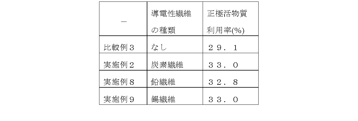
(比較例1、実施例2、8、9)
平均粒子径が500μmの鱗片状のグラファイトを、正極活物質中に0.5質量%含み、リン酸を0.5質量%含む制御弁式据鉛蓄電池を作製して試験した。
【0032】
導電性繊維の種類として前記した炭素繊維以外の鉛繊維、錫繊維についても実験した。なお、各種導電性繊維の正極活物質中での含有量を0.5質量%とした。その他の制御弁式鉛蓄電池も作製条件や試験条件は、上記したものである。
【0033】
初期の正極活物質利用率の測定をした結果を表3に示す。導電性繊維の種類として炭素繊維に限られず、鉛繊維、錫繊維を添加したいずれの場合においても正極活物質利用率の向上が認められた。
【0034】
【表3】
【発明の効果】
上述したように、本発明を用いることによって、従来に比べて正極活物質利用率が高く、長寿命の制御弁式鉛蓄電池を提供できるため優れたものである。[0001]
[Technical field to which the invention belongs]
The present invention relates to a valve-regulated lead-acid battery.
[0002]
[Prior art]
Control valve type lead-acid batteries are widely used as power sources for uninterruptible power supplies because they are inexpensive and highly reliable. However, in general, a lead storage battery has a higher density of lead used as a current collector and an active material than other batteries, and a mass energy density is lower than that of other batteries.
[0003]
In addition, the control valve type lead-acid battery generally uses a paste-type electrode plate produced by applying a paste-like active material to a lattice body using a lead alloy as a positive electrode plate and a negative electrode plate.
[0004]
In order to increase the mass energy density of the control valve type lead-acid battery, a technique for improving the utilization rate of the positive electrode active material used in the positive electrode plate is effective. In order to improve the utilization rate of the positive electrode active material, means for making the positive electrode active material porous is used.
[0005]
That is, by making the positive electrode active material porous, it is possible to include a large amount of electrolyte in the active material. As a result, the reaction area of the electrode increases, so that the utilization rate of the positive electrode active material is increased. It will improve.
[0006]
As a means for making the positive electrode active material porous, after preparing a paste-like active material containing lead oxide powder as a main component and increasing the amount of moisture, the paste-like active material is a lattice made of a lead alloy. A method of aging and drying after applying to the body is generally used.
[0007]
[Problems to be solved by the invention]
However, if the amount of water in the pasty active material is too large, the pasty active material becomes too soft and it is difficult to fill the lattice. On the other hand, in a positive electrode plate produced using a paste-like active material having a large amount of moisture, the adhesion strength between particles constituting the positive electrode active material is reduced. Therefore, there is a problem that the positive electrode active material is easily dropped from the lattice body and has a short life.
[0008]
An object of the present invention is to provide a control valve type stationary lead-acid battery having a high utilization rate of a positive electrode active material and a long life.
[0009]
[Means for Solving the Problems]
In order to solve the above-described problems, the first invention is a control valve type lead-acid battery using carbon powder and conductive fibers in the positive electrode active material, wherein phosphoric acid is contained in the positive electrode active material. The second aspect of the invention is characterized in that the phosphoric acid is contained in the positive electrode active material in an amount of 0.1 to 1% by mass, and the third aspect of the invention is that the carbon powder has an average particle diameter. Is a flaky graphite having a thickness of 100 μm or more, and the fourth invention is characterized in that the conductive fiber is any one of carbon fiber, lead fiber, and tin fiber.
[0010]
DETAILED DESCRIPTION OF THE INVENTION
1. Preparation and test conditions of positive electrode plate Conventionally used lead powder mainly composed of lead monoxide, red lead, scaly graphite with various particle sizes described later, various conductive fiber fibers, water, dilute sulfuric acid and resin Using fibers as raw materials, these were kneaded by a conventional method to prepare a paste-like active material for a positive electrode. In addition, the moisture content was adjusted so that the paste-form active material for the positive electrode had a hardness that could be applied to the lattice.
[0011]
As the flaky graphite, one having an average particle size of 10 to 500 μm (manufactured by Nippon Graphite) was used. As the conductive fiber fibers, carbon fibers having an average diameter of about 10 μm (manufactured by Toray), lead fibers having an average diameter of about 20 μm, and tin oxide fibers having an average diameter of about 20 μm were used.
[0012]
As described later, in the present invention, a predetermined amount of 85% by mass aqueous solution of orthophosphoric acid (H 3 PO 4 ) described later was added to these raw materials and kneaded to prepare a paste-like active material for a positive electrode.
[0013]
Using the pasty active material thus prepared, a positive electrode plate was prepared by a normal method. That is, the paste-like active material is filled into a lattice body made of lead-calcium-tin alloy having a height of 115 mm, a width of 60 mm, and a thickness of 4.0 mm. Then, after aging in an atmosphere having a temperature of 35 to 45 ° C. and a relative humidity of 90% or more, it was dried to obtain a paste type positive electrode plate.
[0014]
2. Production conditions for a control valve type lead-acid battery: A paste-type positive electrode plate produced by the above-described method and a conventional lead-calcium-tin alloy having a height of 115 mm, a width of 60 mm, and a thickness of 2.0 mm. A paste-type negative electrode plate using a lattice was used.
[0015]
Then, using a conventional method, three paste-type positive electrode plates and four paste-type negative electrode plates are used via a retainer, and welded to create an electrode plate group, to the battery case of the electrode plate group A control valve type lead-acid battery is fabricated by assembling a polypropylene spacer having a thickness of 1 mm in contact with both side surfaces of the electrode plate group so that the group pressure at the time of insertion becomes 20 kPa.
[0016]
Then, the battery was formed with the diluted sulfuric acid electrolyte injected, and a control valve type lead-acid battery having a 20 hour discharge capacity of 15 Ah and a nominal voltage of 2 V was produced.
[0017]
3. Test Condition of Control Valve Type Lead Acid Battery The initial discharge time and the discharge time after the acceleration test were measured under the following conditions for the product of the present invention described above and the control valve type lead acid batteries of various comparative examples described later.
[0018]
The produced control valve type lead acid batteries are discharged at a constant current of 25 ° C. and 2.4 A to a final voltage of 1.7 V / cell to measure their discharge capacities. And the positive electrode active material utilization rate was compared from the filling amount of the positive electrode active material and the theoretical capacity.
[0019]
After the initial discharge test, the battery was continuously overcharged at a constant current of 0.45 A in a constant temperature bath at 25 ° C. And every 30 days, discharge at a constant current of 2.4 A (25 ° C., discharge end voltage: 1.7 V), measure the discharge time, and when the discharge capacity becomes 10.8 Ah or less, the control valve The life of the lead-acid battery.
[0020]
【Example】
As shown below, an experiment was performed using paste type positive electrode plates having different raw materials for the paste-like active material.
[0021]
(Comparative Example 1)
A control valve type lead-acid battery using a paste-like active material containing no carbon fiber, graphite and phosphoric acid in the positive electrode active material was produced and tested. The production conditions and test conditions of the other control valve type lead-acid batteries are as described above.
[0022]
(Comparative Example 2)
A control valve type lead acid battery using a paste-like active material containing 0.5% by mass of carbon fiber and not containing graphite and phosphoric acid in the positive electrode active material was prepared and tested. The production conditions and test conditions of the other control valve type lead-acid batteries are as described above.
[0023]
(Comparative Example 3)
A control valve type lead-acid battery using a paste-like active material containing 0.5% by mass of scaly graphite having an average particle diameter of 500 μm in the positive electrode active material and not containing carbon fiber and phosphoric acid was tested. . The production conditions and test conditions of the other control valve type lead-acid batteries are as described above.
[0024]
(Comparative Example 4)
A control valve type lead-acid battery using a paste active material containing 0.5% by mass of carbon fiber and scaly graphite having an average particle diameter of 500 μm in the positive electrode active material and not containing phosphoric acid was prepared and tested. . The production conditions and test conditions of the other control valve type lead-acid batteries are as described above.
[0025]
(Examples 1-4)
As shown in Table 1, the positive electrode active material contains 0.5% by mass of carbon fibers which are conductive fibers and scaly graphite having an average particle diameter of 500 μm as carbon powder. And in Examples 1-4, the control valve type lead acid battery which contains 0.1, 0.5, 1.0, and 2.0 mass% of phosphoric acid in a positive electrode active material, respectively was produced and tested. The production conditions and test conditions of the other control valve type lead-acid batteries are as described above.
[0026]
Table 1 shows the results of the initial positive electrode active material utilization rate test and the life test. Regardless of whether or not phosphoric acid is contained, the valve-regulated lead acid battery containing both carbon fiber and graphite has a high positive electrode active material utilization rate but a single life (Comparative Examples 1 to 4).
On the other hand, it can be seen that the life characteristics are improved by adding phosphoric acid. Moreover, since it is recognized that lifetime performance will fall when phosphoric acid content exceeds 1 mass%, it turns out that it is preferable to make phosphoric acid content into 1 mass% or less.
[0027]
[Table 1]
(Comparative Example 1, Examples 2, 5-7)
A control valve type lead-acid battery containing 0.5% by mass of flaky graphite having an average particle diameter of 10, 50, 100, and 500 μm in the positive electrode active material was prepared and tested. The positive electrode active material contained 0.5% by mass of phosphoric acid and 0.5% by mass of carbon fiber. The production conditions and test conditions of the other control valve type lead-acid batteries are as described above.
[0029]
Table 2 shows the results of the measurement of the initial positive electrode active material utilization rate. By adding graphite having an average particle size of 100 μm or more, the initial active material utilization rate is improved. The control valve type lead-acid battery was disassembled and the porosity of the positive electrode active material was measured. As a result, the porosity increased by about 2% when graphite having an average particle size of 100 μm was added. By adding graphite having an average particle size of 100 μm or more, the amount of the electrolyte contained in the active material is increased, and it is considered that the utilization factor of the positive electrode active material is improved.
[0030]
[Table 2]
(Comparative Example 1, Examples 2, 8, and 9)
A control valve type stationary lead-acid storage battery containing 0.5% by mass of scale-like graphite having an average particle diameter of 500 μm in the positive electrode active material and 0.5% by mass of phosphoric acid was produced and tested.
[0032]
Experiments were also conducted on lead fibers and tin fibers other than the carbon fibers described above as the types of conductive fibers. In addition, content in the positive electrode active material of various conductive fibers was 0.5 mass%. The production conditions and test conditions of the other control valve type lead-acid batteries are as described above.
[0033]
Table 3 shows the results of the measurement of the initial positive electrode active material utilization rate. The type of conductive fiber is not limited to carbon fiber, and an improvement in the utilization rate of the positive electrode active material was observed in any case where lead fiber or tin fiber was added.
[0034]
[Table 3]
【The invention's effect】
As described above, the use of the present invention is superior in that it can provide a control valve type lead storage battery having a higher positive electrode active material utilization rate and a longer life than the conventional one.
Claims (4)
Priority Applications (1)
| Application Number | Priority Date | Filing Date | Title |
|---|---|---|---|
| JP2000331789A JP4635325B2 (en) | 2000-10-31 | 2000-10-31 | Control valve type lead acid battery |
Applications Claiming Priority (1)
| Application Number | Priority Date | Filing Date | Title |
|---|---|---|---|
| JP2000331789A JP4635325B2 (en) | 2000-10-31 | 2000-10-31 | Control valve type lead acid battery |
Publications (2)
| Publication Number | Publication Date |
|---|---|
| JP2002141066A JP2002141066A (en) | 2002-05-17 |
| JP4635325B2 true JP4635325B2 (en) | 2011-02-23 |
Family
ID=18808084
Family Applications (1)
| Application Number | Title | Priority Date | Filing Date |
|---|---|---|---|
| JP2000331789A Expired - Lifetime JP4635325B2 (en) | 2000-10-31 | 2000-10-31 | Control valve type lead acid battery |
Country Status (1)
| Country | Link |
|---|---|
| JP (1) | JP4635325B2 (en) |
Families Citing this family (10)
| Publication number | Priority date | Publication date | Assignee | Title |
|---|---|---|---|---|
| JP2009252606A (en) * | 2008-04-09 | 2009-10-29 | Shin Kobe Electric Mach Co Ltd | Manufacturing method of lead acid storage battery |
| MX2012010082A (en) * | 2010-03-01 | 2012-09-12 | Shin Kobe Electric Machinery | ACID-LEAD ACCUMULATOR. |
| JP5598532B2 (en) * | 2010-03-02 | 2014-10-01 | 新神戸電機株式会社 | Lead acid battery |
| BR112012028803A2 (en) * | 2010-05-10 | 2016-07-26 | Shin Kobe Electric Machinery | lead accumulator battery |
| WO2012042917A1 (en) * | 2010-09-30 | 2012-04-05 | 新神戸電機株式会社 | Lead storage battery |
| RU2013133847A (en) * | 2010-12-21 | 2015-01-27 | Син-Кобе Электрик Машинери Ко., Лтд. | LEAD ACID BATTERY |
| EP2709200B1 (en) | 2011-05-13 | 2016-02-10 | Shin-Kobe Electric Machinery Co., Ltd. | Lead battery |
| JP5445655B2 (en) * | 2012-10-25 | 2014-03-19 | 新神戸電機株式会社 | Lead acid battery |
| CN106252609A (en) * | 2016-08-25 | 2016-12-21 | 四川荣联电子科技有限公司 | Slow down the lead-acid accumulator anode diachylon that positive active material comes off |
| CN106099116A (en) * | 2016-08-25 | 2016-11-09 | 四川荣联电子科技有限公司 | Additive for lead-acid accumulator anode diachylon |
Family Cites Families (6)
| Publication number | Priority date | Publication date | Assignee | Title |
|---|---|---|---|---|
| JPS5422532A (en) * | 1977-07-20 | 1979-02-20 | Japan Storage Battery Co Ltd | Wetttype instant usable lead storage battery |
| JPH0268857A (en) * | 1988-09-02 | 1990-03-08 | Matsushita Electric Ind Co Ltd | Lead-acid battery manufacturing method |
| JPH06103978A (en) * | 1992-09-24 | 1994-04-15 | Shin Kobe Electric Mach Co Ltd | Lead plate for lead battery |
| JPH0837008A (en) * | 1994-07-21 | 1996-02-06 | Japan Storage Battery Co Ltd | Paste type lead acid battery |
| JPH09115517A (en) * | 1995-10-16 | 1997-05-02 | Yuasa Corp | Sealed lead-acid battery |
| JP2001043861A (en) * | 1999-07-30 | 2001-02-16 | Furukawa Battery Co Ltd:The | Positive plate for lead storage battery and lead storage battery |
-
2000
- 2000-10-31 JP JP2000331789A patent/JP4635325B2/en not_active Expired - Lifetime
Also Published As
| Publication number | Publication date |
|---|---|
| JP2002141066A (en) | 2002-05-17 |
Similar Documents
| Publication | Publication Date | Title |
|---|---|---|
| JP2001229920A (en) | Manufacturing method of sealed lead-acid battery | |
| JP4635325B2 (en) | Control valve type lead acid battery | |
| JP2009048800A (en) | Manufacturing method of paste type positive electrode plate | |
| JP2000251896A (en) | Lead storage battery and method of manufacturing the same | |
| JP5017746B2 (en) | Control valve type lead acid battery | |
| JP4433593B2 (en) | Control valve type lead acid battery | |
| JP2001043849A (en) | Sealed lead-acid battery | |
| JP6628070B2 (en) | Manufacturing method of positive electrode plate for control valve type lead-acid battery | |
| JP2002231247A (en) | Control valve type lead storage battery | |
| JP3835093B2 (en) | Sealed lead acid battery | |
| JP3659111B2 (en) | Manufacturing method of lead acid battery | |
| JP2004055309A (en) | Method for producing paste-like active material for positive electrode and lead storage battery using the same | |
| KR102683933B1 (en) | High capacity energy storage device and manufacturing method of the same | |
| JP2001043863A (en) | Sealed lead-acid battery | |
| JP4501246B2 (en) | Control valve type stationary lead acid battery manufacturing method | |
| JPH09147841A (en) | Negative electrode plate for lead acid battery and its manufacture | |
| JP2001155722A (en) | Sealed lead-acid battery and manufacturing method thereof | |
| JP2003123744A (en) | Control valve type lead storage battery | |
| JPH11339843A (en) | Sealed lead-acid battery | |
| JP4239510B2 (en) | Lead-acid battery and manufacturing method thereof | |
| JP2773311B2 (en) | Manufacturing method of sealed lead-acid battery | |
| JP2001332268A (en) | Control valve type lead-acid battery | |
| JP2002343360A (en) | Control valve type lead storage battery | |
| JP3040718B2 (en) | Lead storage battery | |
| JPH07296845A (en) | Sealed lead acid battery |
Legal Events
| Date | Code | Title | Description |
|---|---|---|---|
| A621 | Written request for application examination |
Free format text: JAPANESE INTERMEDIATE CODE: A621 Effective date: 20070724 |
|
| A977 | Report on retrieval |
Free format text: JAPANESE INTERMEDIATE CODE: A971007 Effective date: 20100830 |
|
| TRDD | Decision of grant or rejection written | ||
| A01 | Written decision to grant a patent or to grant a registration (utility model) |
Free format text: JAPANESE INTERMEDIATE CODE: A01 Effective date: 20101026 |
|
| A01 | Written decision to grant a patent or to grant a registration (utility model) |
Free format text: JAPANESE INTERMEDIATE CODE: A01 |
|
| A61 | First payment of annual fees (during grant procedure) |
Free format text: JAPANESE INTERMEDIATE CODE: A61 Effective date: 20101108 |
|
| FPAY | Renewal fee payment (event date is renewal date of database) |
Free format text: PAYMENT UNTIL: 20131203 Year of fee payment: 3 |
|
| R150 | Certificate of patent or registration of utility model |
Ref document number: 4635325 Country of ref document: JP Free format text: JAPANESE INTERMEDIATE CODE: R150 Free format text: JAPANESE INTERMEDIATE CODE: R150 |
|
| EXPY | Cancellation because of completion of term |