JP4635017B2 - Parking assistance device - Google Patents
Parking assistance device Download PDFInfo
- Publication number
- JP4635017B2 JP4635017B2 JP2007042513A JP2007042513A JP4635017B2 JP 4635017 B2 JP4635017 B2 JP 4635017B2 JP 2007042513 A JP2007042513 A JP 2007042513A JP 2007042513 A JP2007042513 A JP 2007042513A JP 4635017 B2 JP4635017 B2 JP 4635017B2
- Authority
- JP
- Japan
- Prior art keywords
- parking
- vehicle
- steering
- mode
- target position
- Prior art date
- Legal status (The legal status is an assumption and is not a legal conclusion. Google has not performed a legal analysis and makes no representation as to the accuracy of the status listed.)
- Active
Links
Images
Classifications
-
- B—PERFORMING OPERATIONS; TRANSPORTING
- B62—LAND VEHICLES FOR TRAVELLING OTHERWISE THAN ON RAILS
- B62D—MOTOR VEHICLES; TRAILERS
- B62D15/00—Steering not otherwise provided for
- B62D15/02—Steering position indicators ; Steering position determination; Steering aids
- B62D15/027—Parking aids, e.g. instruction means
-
- B—PERFORMING OPERATIONS; TRANSPORTING
- B60—VEHICLES IN GENERAL
- B60R—VEHICLES, VEHICLE FITTINGS, OR VEHICLE PARTS, NOT OTHERWISE PROVIDED FOR
- B60R1/00—Optical viewing arrangements; Real-time viewing arrangements for drivers or passengers using optical image capturing systems, e.g. cameras or video systems specially adapted for use in or on vehicles
- B60R1/20—Real-time viewing arrangements for drivers or passengers using optical image capturing systems, e.g. cameras or video systems specially adapted for use in or on vehicles
- B60R1/22—Real-time viewing arrangements for drivers or passengers using optical image capturing systems, e.g. cameras or video systems specially adapted for use in or on vehicles for viewing an area outside the vehicle, e.g. the exterior of the vehicle
- B60R1/23—Real-time viewing arrangements for drivers or passengers using optical image capturing systems, e.g. cameras or video systems specially adapted for use in or on vehicles for viewing an area outside the vehicle, e.g. the exterior of the vehicle with a predetermined field of view
-
- B—PERFORMING OPERATIONS; TRANSPORTING
- B60—VEHICLES IN GENERAL
- B60R—VEHICLES, VEHICLE FITTINGS, OR VEHICLE PARTS, NOT OTHERWISE PROVIDED FOR
- B60R2300/00—Details of viewing arrangements using cameras and displays, specially adapted for use in a vehicle
- B60R2300/30—Details of viewing arrangements using cameras and displays, specially adapted for use in a vehicle characterised by the type of image processing
- B60R2300/302—Details of viewing arrangements using cameras and displays, specially adapted for use in a vehicle characterised by the type of image processing combining image information with GPS information or vehicle data, e.g. vehicle speed, gyro, steering angle data
-
- B—PERFORMING OPERATIONS; TRANSPORTING
- B60—VEHICLES IN GENERAL
- B60R—VEHICLES, VEHICLE FITTINGS, OR VEHICLE PARTS, NOT OTHERWISE PROVIDED FOR
- B60R2300/00—Details of viewing arrangements using cameras and displays, specially adapted for use in a vehicle
- B60R2300/30—Details of viewing arrangements using cameras and displays, specially adapted for use in a vehicle characterised by the type of image processing
- B60R2300/304—Details of viewing arrangements using cameras and displays, specially adapted for use in a vehicle characterised by the type of image processing using merged images, e.g. merging camera image with stored images
- B60R2300/305—Details of viewing arrangements using cameras and displays, specially adapted for use in a vehicle characterised by the type of image processing using merged images, e.g. merging camera image with stored images merging camera image with lines or icons
-
- B—PERFORMING OPERATIONS; TRANSPORTING
- B60—VEHICLES IN GENERAL
- B60R—VEHICLES, VEHICLE FITTINGS, OR VEHICLE PARTS, NOT OTHERWISE PROVIDED FOR
- B60R2300/00—Details of viewing arrangements using cameras and displays, specially adapted for use in a vehicle
- B60R2300/80—Details of viewing arrangements using cameras and displays, specially adapted for use in a vehicle characterised by the intended use of the viewing arrangement
- B60R2300/806—Details of viewing arrangements using cameras and displays, specially adapted for use in a vehicle characterised by the intended use of the viewing arrangement for aiding parking
-
- B—PERFORMING OPERATIONS; TRANSPORTING
- B60—VEHICLES IN GENERAL
- B60W—CONJOINT CONTROL OF VEHICLE SUB-UNITS OF DIFFERENT TYPE OR DIFFERENT FUNCTION; CONTROL SYSTEMS SPECIALLY ADAPTED FOR HYBRID VEHICLES; ROAD VEHICLE DRIVE CONTROL SYSTEMS FOR PURPOSES NOT RELATED TO THE CONTROL OF A PARTICULAR SUB-UNIT
- B60W30/00—Purposes of road vehicle drive control systems not related to the control of a particular sub-unit, e.g. of systems using conjoint control of vehicle sub-units
- B60W30/06—Automatic manoeuvring for parking
Landscapes
- Engineering & Computer Science (AREA)
- Mechanical Engineering (AREA)
- Multimedia (AREA)
- Chemical & Material Sciences (AREA)
- Combustion & Propulsion (AREA)
- Transportation (AREA)
- Steering Control In Accordance With Driving Conditions (AREA)
- Image Processing (AREA)
- Traffic Control Systems (AREA)
- Image Analysis (AREA)
- Fittings On The Vehicle Exterior For Carrying Loads, And Devices For Holding Or Mounting Articles (AREA)
- Control Of Driving Devices And Active Controlling Of Vehicle (AREA)
Description
本発明は、車両の駐車時の運転操作を支援する駐車支援装置に関する。 The present invention relates to a parking assistance device that assists a driving operation when a vehicle is parked.
このような駐車支援装置として、下記に出典を示す特許文献1に記載された車両の自動操舵装置がある。この自動操舵装置により、車両は、スタート位置から前進し、折り返し位置を経て後進して、目標位置まで案内される。自動操舵装置は、車両が停止状態で目標位置を設定されると、その停止位置をスタート位置と設定する。これにより、スタート位置と目標位置とが定まるので、自動操舵装置は折り返し位置を設定して、前進移動経路、後進移動経路を算出する。車両の現在位置や、駐車目標位置、折り返し位置、スタート位置から駐車位置までの移動経路などは、液晶モニタに表示される。停止状態における目標位置の設定や、駐車モードの選択などは、乗員がモード選択スイッチを操作することによって行われる。
As such a parking assistance device, there is an automatic steering device for a vehicle described in
また、下記に出典を示す特許文献2には、乗員による手動操舵を支援する駐車支援装置が記載されている。この場合も、上記と同様に駐車モードは、乗員によるスイッチの操作によってコントローラに指示される。
Further,
上記特許文献に示された自動操舵装置や駐車支援装置は、車両の駐車に際して乗員の負荷を軽減できるものである。しかし、自動操舵や駐車支援の開始指示の他、駐車モード(駐車形態)についても、手動で指示する必要がある。このような指示入力は、表示装置と一体化されたタッチパネルや別の操作スイッチなどによって構成されている。乗員は駐車形態の設定のために、通常の運転時とは異なる入力手段を操作する必要がある。従って、さらに利便性の高い駐車支援装置を得るために、より簡単な方法で駐車形態を指示することが求められる。 The automatic steering device and the parking assist device disclosed in the above patent document can reduce the load on the occupant when the vehicle is parked. However, it is necessary to manually instruct the parking mode (parking mode) in addition to the instruction to start automatic steering and parking assistance. Such an instruction input is constituted by a touch panel integrated with the display device, another operation switch, or the like. The occupant needs to operate an input means different from that during normal driving in order to set the parking mode. Therefore, in order to obtain a more convenient parking assistance device, it is required to instruct the parking mode by a simpler method.
本願発明は、上記課題に鑑みて創案されたもので、簡単な方法で駐車形態を指示することができる利便性の高い駐車支援装置を提供することを目的とする。 The present invention has been made in view of the above problems, and an object of the present invention is to provide a highly convenient parking support apparatus that can instruct a parking mode by a simple method.
この目的を達成するため、本発明に係る、車両の駐車を支援する駐車支援装置は、以下の構成を備える。当該駐車支援装置は、
所定の停止位置において前記車両の駐車目標位置を駐車形態ごとに仮設定する駐車目標位置設定部と、
前記駐車目標位置の設定後、乗員によるステアリングの操作に基づいて、前記駐車形態及び当該駐車形態に対応する前記駐車目標位置を決定する駐車形態決定部と、
前記駐車目標位置へ前記車両を誘導する誘導部と、を備えることを特徴とする。
In order to achieve this object, a parking assistance device for assisting in parking a vehicle according to the present invention has the following configuration. The parking assistance device
A parking target position setting unit that temporarily sets the parking target position of the vehicle for each parking mode at a predetermined stop position;
After the setting of the parking target position, based on the steering operation by the occupant, the parking mode determining unit that determines the parking mode and the parking target position corresponding to the parking mode;
A guidance unit for guiding the vehicle to the parking target position.
この特徴構成によれば、運転の際に乗員が操作するステアリングを用いて、駐車形態が指示される。そして、指示された駐車形態に基づいて、駐車形態及び駐車形態に対応する駐車目標位置が決定される。本発明によれば、乗員はステアリングから手を離すことなく、簡単な方法で駐車形態を指示することができるので、利便性の高い駐車支援装置を提供することができる。 According to this characteristic configuration, the parking mode is instructed using the steering operated by the occupant during driving. And based on the instruct | indicated parking form, the parking target position corresponding to a parking form and a parking form is determined. According to the present invention, since the occupant can instruct the parking mode by a simple method without releasing his hand from the steering wheel, a highly convenient parking assistance device can be provided.
また、本発明に係る駐車支援装置は、前記駐車形態決定部が、前記所定の停止位置の近傍において前記ステアリングが所定の操作量以上操作されなかった場合に、前記駐車形態が縦列駐車であると決定し、前記所定の操作量以上操作された場合に、前記駐車形態が車庫入れ駐車であると決定することを特徴とする。 Further, in the parking assist device according to the present invention, when the parking mode determination unit is not operated more than a predetermined operation amount in the vicinity of the predetermined stop position, the parking mode is parallel parking. When it is determined and operated more than the predetermined operation amount, it is determined that the parking mode is garage parking.
縦列駐車を行う場合、一般的には、駐車目標位置を通り過ぎて直進した後に旋回を伴って後進する運転操作が行われる。つまり、所定の停止近傍からさらに直進する場合の駐車形態は、縦列駐車である。従って、駐車形態決定部は、ステアリングが所定の操作量以上操作されないことによって、駐車形態が縦列駐車であることを判定することができる。そして、この判定結果から駐車目標位置を決定することができる。
一方、車庫入れ駐車を行う場合、一般的には、駐車目標位置から旋回を伴って斜め前方へ進行した後に逆方向への旋回を伴って後進する。つまり、所定の停止位置から斜め前方へ進行する場合の駐車形態は、車庫入れ駐車である。従って、駐車形態決定部は、ステアリングが所定の操作量以上操作されることによって、駐車形態が車庫入れ駐車であることを判定することができる。そして、この判定結果から駐車目標位置を決定することができる。
また、上記ステアリングの操作は、所定の停止位置から前方に車両を前進させる際の操舵方向と良く一致している。従って、ステアリングの操作が無駄になることはない。また、特に車庫入れ駐車の場合には、前進を開始する時点で旋回を開始できるので、所定の停止位置から後退を開始する折り返し位置までの移動距離を短くすることができる。
When performing parallel parking, in general, a driving operation is performed in which the vehicle goes straight past the parking target position and then moves backward with a turn. That is, the parking form in the case of further going straight from the vicinity of the predetermined stop is parallel parking. Therefore, the parking form determination unit can determine that the parking form is parallel parking when the steering is not operated more than a predetermined operation amount. And a parking target position can be determined from this determination result.
On the other hand, when garage parking is performed, generally, the vehicle travels diagonally forward with a turn from the parking target position and then moves backward with a turn in the reverse direction. That is, the parking form in the case of traveling diagonally forward from the predetermined stop position is garage parking. Therefore, the parking mode determination unit can determine that the parking mode is garage parking by operating the steering more than a predetermined operation amount. And a parking target position can be determined from this determination result.
Further, the steering operation is in good agreement with the steering direction when the vehicle is moved forward from a predetermined stop position. Therefore, the steering operation is not wasted. In particular, in the case of parking in a garage, the turn can be started at the time when the forward movement is started, so that the movement distance from the predetermined stop position to the return position where the backward movement is started can be shortened.
また、本発明に係る駐車支援装置は、前記駐車形態決定部が、前記所定の停止位置の近傍において前記ステアリングが所定の操作量以上左回りに操作された場合に、前記駐車形態が右車庫入れ駐車であると決定し、所定の操作量以上右回りに操作された場合に、前記駐車形態が左車庫入れ駐車であると決定することを特徴とする。 Further, the parking assist device according to the present invention is configured such that when the parking mode determination unit operates the steering counterclockwise more than a predetermined operation amount in the vicinity of the predetermined stop position, the parking mode is stored in the right garage. It is determined that the vehicle is parked, and when the vehicle is operated clockwise more than a predetermined operation amount, the parking mode is determined to be left garage parking.
車庫入れ駐車を行う場合、一般的には、駐車目標位置とは反対方向への旋回を伴って斜め前方へ進行した後に駐車目標位置へ向かう旋回を伴って後進する。つまり、最初に所定の停止位置から左斜め前方へ進行する場合の駐車形態は、右車庫入れ駐車である。また、最初に所定の停止位置から右斜め前方へ進行する場合の駐車形態は、左車庫入れ駐車である。従って、駐車形態決定部は、車庫入れ駐車の方向を良好に判定することができる。そして、この判定結果から駐車目標位置を決定することができる。
また、上記ステアリングの操作は、所定の停止位置から前方に車両を前進させる際の操舵方向と良好に一致している。従って、駐車形態を決定するためのステアリングの操作を前進の際に有効に利用することができ、後退を開始する折り返し位置までの移動距離を短くすることができる。また、駐車形態を決定するためのステアリング操作が手動により車庫入れ駐車を行う際の操作と同じため、乗員は違和感を覚えることなく駐車形態の指示入力を行うことができる。
When garage parking is performed, generally, the vehicle travels diagonally forward with a turn in the direction opposite to the parking target position, and then moves backward with a turn toward the parking target position. That is, the parking mode in the case where the vehicle first proceeds diagonally leftward from a predetermined stop position is right garage parking. In addition, the parking mode when the vehicle first proceeds diagonally right forward from a predetermined stop position is left garage parking. Therefore, the parking form determination unit can satisfactorily determine the direction of parking in the garage. And a parking target position can be determined from this determination result.
Further, the steering operation is in good agreement with the steering direction when the vehicle is advanced forward from the predetermined stop position. Therefore, the steering operation for determining the parking mode can be used effectively at the time of forward movement, and the moving distance to the return position at which the backward movement is started can be shortened. Further, since the steering operation for determining the parking mode is the same as the operation for manually parking in the garage, the occupant can input the parking mode instruction without feeling uncomfortable.
また、本発明に係る駐車支援装置は、前記誘導部が、前記車両を前記所定の停止位置よりも前方の後退開始位置へ誘導した後に、前記車両を前記後退開始位置よりも後方の前記駐車目標位置へ誘導するものであり、
前記駐車形態決定部は、前記車両が前記後退開始位置へ到達した後、前記後退開始位置の近傍において前記ステアリングが、所定の操作量以上右回りに操作された場合に、前記駐車形態が右縦列駐車であると決定し、所定の操作量以上左回りに操作された場合に、前記駐車形態が左縦列駐車であると決定することを特徴とする。
Further, in the parking assist device according to the present invention, the guide unit guides the vehicle to a backward start position ahead of the predetermined stop position, and then the parking target behind the reverse start position. To the position,
When the steering is operated clockwise more than a predetermined operation amount in the vicinity of the reverse start position after the vehicle has reached the reverse start position, the parking type determination unit determines that the parking type is a right column. It is determined that the vehicle is parked, and when the vehicle is operated counterclockwise by a predetermined operation amount or more, the parking mode is determined to be left parallel parking.
縦列駐車の場合は、一般的には、駐車目標位置を通り過ぎて直進した後に旋回を伴って後進する運転操作が行われる。この旋回は、右方向への駐車の場合には右方向、左方向への駐車の場合には左方向である。従って、駐車形態決定部は、後退開始位置到達後にステアリングが所定の操作量以上操作されることによって、縦列駐車の方向を判定することができる。そして、この判定結果から駐車目標位置を決定することができる。
また、駐車形態を決定するためのステアリング操作が手動により縦列駐車を行う際の操作と同じため、乗員は違和感を覚えることなく駐車形態の指示入力を行うことができる。
In the case of parallel parking, generally, a driving operation is performed in which the vehicle goes straight past the parking target position and then moves backward with a turn. This turn is in the right direction for parking in the right direction and in the left direction in parking in the left direction. Therefore, the parking mode determination unit can determine the direction of parallel parking by operating the steering more than a predetermined operation amount after reaching the reverse start position. And a parking target position can be determined from this determination result.
Further, since the steering operation for determining the parking mode is the same as the operation for manually performing parallel parking, the occupant can input the parking mode instruction without feeling uncomfortable.
また、本発明に係る駐車支援装置は、前記駐車形態決定部が、前記車両の停止時における前記ステアリングの操作に基づいて、前記駐車形態を決定することを特徴とする。 Moreover, the parking assistance device according to the present invention is characterized in that the parking form determination unit determines the parking form based on an operation of the steering when the vehicle is stopped.
車両の停止時におけるステアリングの操作に基づいて駐車形態を決定が決定されると、より確実にステアリングの操作量を判定することができる。また、車両が動く前に駐車形態が決定されるので、その後の誘導経路を迅速に演算することができる。 When the parking mode is determined based on the steering operation when the vehicle is stopped, the steering operation amount can be more reliably determined. Further, since the parking mode is determined before the vehicle moves, the subsequent guidance route can be calculated quickly.
また、本発明に係る駐車支援装置は、前記誘導部が、前記駐車目標位置へ、前記後退開始位置を経由して前記車両を自動操舵制御するものであり、
前記ステアリングが、
前記駐車支援の開始後、前記自動操舵制御の開始前において前記駐車形態決定部に対する前記駐車形態の指示入力手段であり、
前記自動操舵制御の開始後、前記自動操舵の完了前において前記誘導部に対する前記自動操舵制御の中止入力手段である、ことを特徴とする。
Further, in the parking assist device according to the present invention, the guide unit automatically steering-controls the vehicle to the parking target position via the reverse start position,
The steering is
After the start of the parking support, before the start of the automatic steering control is an instruction input means of the parking mode for the parking mode determination unit,
The automatic steering control stop input means for the guiding unit after the automatic steering control is started and before the automatic steering is completed.
当該駐車支援装置が車両を自動操舵制御するものである場合、駐車形態の指示や、自動操舵の中止のための入力手段が別途必要とされる場合がある。しかし、本特徴によれば、駐車形態の指示を行う指示入力手段や、自動操舵制御を中止させる中止入力手段が、共にステアリングの操作によって実現される。そして、両者は、どの時点で操作されるかによって区別されるために混同されることもない。従って、簡単な構成で利便性の高い駐車支援装置を提供することができる。 When the parking assist device automatically controls the vehicle, a parking mode instruction or an input unit for stopping the automatic steering may be separately required. However, according to this feature, both the instruction input means for instructing the parking mode and the stop input means for stopping the automatic steering control are realized by the steering operation. And both are not confused because they are distinguished depending on when they are operated. Therefore, it is possible to provide a parking assistance device with a simple configuration and high convenience.
〔第1実施形態〕
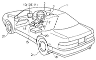
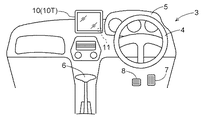
以下、本発明の実施形態を図面に基づいて説明する。ここでは、自動操舵制御を実施する駐車支援装置を例として説明する。図1〜図3は車両1の基本構成を示したものである。
運転席3のステアリング4は回転操作力を前車輪2fに伝えて駆動操向を行うパワーステアリングユニット33と連動している。車体前部にはエンジン32と、このエンジン32からの動力を変速して前車輪2fに伝えるトルクコンバータやCVT等を有する変速機構34とが配置されている。運転席3の近傍には走行速度を制御するアクセル操作手段としてのアクセルペダル7と、前車輪2f及び後車輪2rのブレーキ装置31を操作して前車輪2f及び後車輪2rに制動力を作用させるブレーキペダル8とが並列配置されている。
[First Embodiment]
Hereinafter, embodiments of the present invention will be described with reference to the drawings. Here, a parking assistance device that performs automatic steering control will be described as an example. 1 to 3 show a basic configuration of the
The
運転席3の近傍のコンソールの上部位置には表示面にタッチパネル10Tが形成されたモニタ10(表示部)が備えられている。このモニタ10には、スピーカ11が備えられている。尚、スピーカ11はパネル5や、ドアの内側に備えられても良い。モニタ10は、バックライトを備えた液晶式のものである。もちろん、プラズマ表示型のものやCRT型のものであっても良い。また、タッチパネル10Tは、感圧式のものや静電式のものが使用され、指等の接触位置をロケーションデータとして出力する。本実施形態では、モニタ10はナビゲーションシステムの表示装置として用いるものが兼用されている。
本実施形態においては、後述するように、モニタ10のタッチパネル10Tは駐車支援開始の指示入力手段として用いられる。従って、駐車支援開始の指示入力手段として他のスイッチなどを有している場合には、必ずしもモニタ10を備える必要はない。
A monitor 10 (display unit) having a
In this embodiment, as will be described later, the
ステアリング4の操作系にはステアリングセンサ14が備えられ、ステアリング操作方向と操作量とが計測される。シフトレバー6の操作系にはシフト位置センサ15が備えられ、シフト位置が判別される。アクセルペダル7の操作系にはアクセルセンサ16が備えられ、操作量が計測される。ブレーキペダル8の操作系にはブレーキセンサ17が備えられ、操作の有無などを検出する。
A
また、移動距離センサとして、前車輪2f及び後車輪2rの少なくとも一方の回転量を計測する回転センサ18が備えられている。もちろん、変速機構34において、駆動系の回転量から車両1の移動量を計測してもよい。また、車両1には駐車支援を含む走行制御を行うECU(electronic control unit)20が配置されている。
In addition, a
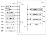
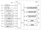
図4は、本発明の駐車支援装置の構成を模式的に示すブロック図である。本発明の駐車支援装置は、ECU20を中核として構成される。ECU20は、情報の入出力を行う入出力インターフェース21を備えると共に、この入出力インターフェース21からの情報を処理するマイクロプロセッサを備えている。もちろん、入出力インターフェース21の一部又は全てがマイクロプロセッサに含まれていてもよい。ECU20は、マイクロプロセッサを中核部品とする電子回路により構成されている。
FIG. 4 is a block diagram schematically showing the configuration of the parking assistance apparatus of the present invention. The parking assist device of the present invention is configured with the
図4に示すように、タッチパネル10T、ステアリングセンサ14、シフト位置センサ15、アクセルセンサ16、ブレーキセンサ17、回転センサ18などからの情報が入力される入力系が形成される。また、モニタ10、スピーカ11、パワーステアリングユニット33に制御信号を出力する出力系が形成される。本実施形態における自動操舵では、制動や変速機構の制御は報知のみで、制動及びシフトチェンジは乗員による操作に委ねられる。また、ナビゲーションシステムを搭載していない場合など、モニタ10を有していない場合には、報知はスピーカ11を介しての音声によってのみ行われる。また、モニタ10を有しておらず、タッチパネル10Tがない場合には、上述したようにスイッチなど、他の指示入力手段から情報が入力系に入力される。
As shown in FIG. 4, an input system for inputting information from the
ECU20は、入出力インターフェース(I/O)21と接続された各機能部を有している。この接続は、例えば、マイクロプロセッサ内のデータバス、アドレスバス、コントロールバス、メモリなどを介して行われるが、説明を容易にするため、詳細な図示及び説明は省略する。
図4に示すように、ECU20は、駐車目標位置設定部23と、駐車形態決定部25と、移動状態検出部27と、誘導部29とを有している。本実施形態においては、これら各機能部は、マイクロプロセッサとプログラムとの協働によって実現される場合を例示している。しかし、論理回路などを用いたハードウェアで構成することも可能である。
The
As shown in FIG. 4, the
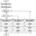
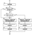
以下、図5に示すフローチャートも利用して、本発明の駐車支援装置による駐車支援の手順を説明する。
駐車支援を受ける乗員は、車両1を駐車させたい場所(駐車予定場所)に対する所定の停止位置に車両1を停車させる。そして、この所定の停止位置において駐車支援の開始指示をECU20に与える。一例として、乗員は、タッチパネル10Tなどの指示入力手段を介して、駐車支援開始の指示を行う。ECU20は、入出力インターフェース21を介して受け取った開始指示を確認する(#1)。
Hereinafter, the procedure of parking assistance by the parking assistance apparatus of the present invention will be described using the flowchart shown in FIG.
An occupant who receives parking assistance stops the
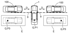
図6及び図7は、上記所定の停止位置を示す説明図である。乗員は駐車予定場所の前方や隣に駐車された駐車車両100など、駐車予定場所の端部を指定可能な場所に車両1を停車させる。具体的には、縦列駐車の場合には、図6に示すように、車両1のドアミラー9と、駐車予定場所の端部とが車両1の横方向に一直線となる位置で停車させる。車庫入れ駐車の場合には、図7に示すように、車両1のドアミラー9と、駐車予定場所の端部とが車両1の横方向に一直線となる位置で停車させる。これらにおいて車両1は、駐車予定場所から車両1の横方向に所定の距離D離れた位置に停車させる。これにより、車両1が水平面上に存在すると仮定した場合の、駐車予定場所と車両1との2次元座標上での関係が定まる。
6 and 7 are explanatory diagrams showing the predetermined stop position. The occupant stops the
上述したように、駐車支援の開始指示は、所定の停止位置において実施される。従って、駐車目標位置設定部23は、車両1の基準位置Qを基準として駐車目標を設定することができる。
縦列駐車の場合には、図6に示すように支援開始位置(所定の停止位置)P1に対して、駐車目標位置P3及び駐車目標エリアEを設定することができる。そして、誘導部29は図8に示すように支援開始位置P1から後退開始位置P2まで直進前進し、旋回を伴って後退開始位置P2から駐車目標位置P3まで後進する誘導経路を設定することができる。
車庫入れ駐車の場合には、駐車目標位置設定部23は、図7に示すように支援開始位置(所定の停止位置)P1に対して、駐車目標位置P3及び駐車目標エリアEを設定することができる。そして、誘導部29は図9に示すように支援開始位置P1から後退開始位置P2まで旋回を伴って前進し、さらに後退開始位置P2から駐車目標位置P3まで逆方向の旋回を伴って後進する誘導経路を設定することができる。
As described above, the parking assistance start instruction is executed at a predetermined stop position. Therefore, the parking target
In the case of parallel parking, as shown in FIG. 6, the parking target position P3 and the parking target area E can be set with respect to the support start position (predetermined stop position) P1. Then, as shown in FIG. 8, the
In the case of garage parking, the parking target
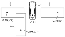
但し、車両1が所定の停止位置(支援開始位置P1)に停車した状態では、まだ、縦列駐車、車庫入れ駐車などの駐車形態は定まっていない。従って、車両1が所定の停止位置において停車し、駐車支援の開始指示が与えられた時点では、図10に示す全ての駐車目標位置P3及び駐車目標エリアEが仮設定される(図5#2)。即ち、車両1の右方向への車庫入れ駐車の場合の駐車目標位置p31、左方向への車庫入れ駐車の場合の駐車目標位置p32、及び車両1の左方向への縦列駐車の場合の駐車目標位置p33が、駐車目標位置P3として仮設定される。
However, in a state where the
ここで、再び図8及び図9を参照すると、縦列駐車の場合には車両1は支援開始位置P1から直進前進する。一方、車庫入れ駐車の場合には車両1は駐車方向に応じて旋回を伴って前進する。図9に示すように、左車庫入れを行う場合には、右前方へ旋回を伴って前進する。図示は省略したが、右車庫入れを行う場合には、左前方へ旋回を伴って前進する。このように、支援開始位置P1からの動きは、駐車形態によってそれぞれ異なっている。
Here, referring to FIGS. 8 and 9 again, in the case of parallel parking, the
そこで、駐車形態決定部25は、入出力インターフェース21及びスピーカ11を介して、乗員にステアリング4の操作を促す。具体的には、右車庫入れの場合にはステアリング4を左回りに操作するように、左車庫入れの場合にはステアリング4を右回りに操作するように音声で報知する。このとき、ステアリング4の操作量も同時に報知する。例えば、左又は右方向への最大舵角や、ステアリング4の1回転分、2回転分など、定量的な数値で報知する。一方、縦列駐車の場合にはステアリング4の操作をしないように音声で報知する。
Therefore, the parking
駐車形態決定部25は、ステアリング4の操作量が所定の操作量A以上か否かを判定し(図5#3)、駐車形態が縦列駐車であるか、車庫入れ駐車であるかを決定する。具体的には、ステアリング4の操作量が所定の操作量A以上の場合には車庫入れ駐車であると判定する。また、ステアリング4の操作量が所定の操作量A未満の場合には縦列駐車であると決定する(#71)。
さらに、駐車形態決定部25は、ステアリング4の操作量が所定の操作量A以上の場合には、その操作方向の左右を判定する(図5#4)。そして、駐車形態が右縦列駐車であるか左縦列駐車であるかを決定する。具体的には、操作方向が左の場合には右車庫入れ駐車であると決定し(#51)、操作方向が右の場合には左車庫入れ駐車であると決定する(#61)。
尚、初期状態の駐車形態を縦列駐車とし、ステアリングが所定の操作量A以上操作された場合に、車庫入れ駐車に切り替えてもよい。
The parking
Furthermore, when the operation amount of the
The parking mode in the initial state may be parallel parking, and may be switched to garage parking when the steering is operated by a predetermined operation amount A or more.
尚、この決定のタイミングは、乗員が駐車支援の指示を行ってから所定時間経過後としてもよいし、乗員がブレーキペダル7を緩めて車両1をクリープ現象により発進させた時点としてもよい。また、その両方でもよい。例えば、乗員が駐車支援の指示を行って直ちに車両1を発進させた場合には、所定時間の経過に拘らず、駐車形態を縦列駐車と決定してもよい。
The timing of this determination may be after a predetermined time has elapsed after the occupant gives an instruction for parking assistance, or may be a point in time when the occupant releases the brake pedal 7 and starts the
駐車形態決定部23は、駐車目標位置の仮設定後、即ち駐車支援開始の指示が与えられた後のステアリング4の操作に基づいて駐車形態を決定する。この「ステアリング4の操作」には、駐車支援開始の指示入力前に舵角が与えられている場合をも含むものである。例えば、乗員が車両1を所定の停止位置(支援開始位置P1)に停車させた後、ステアリング4を操作してから駐車支援の指示を行うような場合をも含むものである。駐車形態決定部23は、駐車支援開始の指示が与えられた後であって、所定時間経過後又は車両1の発進時のステアリング4の操作量(操舵角)に基づいて駐車形態を決定する。
The parking
また、駐車形態の決定は、必ずしも、所定の停止位置において車両1が完全に停止している状態で行われる必要はない。若干の移動を伴いながら決定されたり、若干の移動後の停止位置で決定されたりしてもよい。つまり、駐車形態の決定は、所定の停止位置の近傍で行われてもよい。
Further, the determination of the parking mode is not necessarily performed in a state where the
このように、本実施形態によればタッチパネル10Tなどの特定の入力手段を別途用いることなく、乗員が運転中に握っているステアリング4を指示入力手段として駐車形態を好適に設定することができる。また、上述したように、ステアリング4の操作量は定量的な数値で報知されるので、支援開始位置P1からの移動の際の初期舵角も同時に設定される。
本例では自動操舵により支援開始位置P1から駐車目標位置P3までの駐車支援を実施する。自動操舵においては、アクチュエータ(例えばモータ)によってパワーステアリングユニット33を駆動する。車両1が停車中では静摩擦係数が大きく、アクチュエータによるパワーステアリングユニット33の駆動が困難である。従って、車両1が移動している時に操舵角を中立位置の状態から旋回角へと駆動させる必要がある。しかし、必要な舵角に達するまでの余計な移動を要するため、駐車支援を行う際の移動距離が長くなる。そのため、駐車支援のために必要なスペースが大きくなって狭い駐車場などでは駐車支援が利用できなくなるなど利便性を損なう可能性がある。しかし、本実施形態では、支援開始位置P1からの移動の際の初期舵角が乗員によって設定されるのでこれらの問題を解決することができる。
As described above, according to the present embodiment, the parking mode can be suitably set by using the
In this example, parking assistance from the assistance start position P1 to the parking target position P3 is performed by automatic steering. In automatic steering, the
駐車形態決定部25によって駐車形態が決定されると、誘導部29によって駐車目標位置P3への誘導が開始される。まず初めに、後退開始位置P2までの前進誘導が実施される(図5#51、#61、#71)。車両1が支援開始位置P1から後退開始位置P2へと移動する過程においては、基準点Qが移動するものとして演算が実施される。
When the parking mode is determined by the parking
移動する過程における車両1の位置情報(移動状態)は、移動状態検出部27によって検出される。移動状態検出部27は、図4に示すステアリングセンサ14や回転センサ18、アクセルセンサ16、シフト位置センサ15、ブレーキセンサ17などからの入力に基づいて、車両1の移動状態を検出する。従って、これらのセンサを含めて移動状態検出部27を構成してもよい。また、移動状態検出部27への入力として上記の他、ヨーレートセンサ(不図示)などの他のセンサを用いてもよい。
The position information (movement state) of the
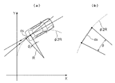
図11は、ステアリングセンサ14や回転センサ18からの入力に基づいて車両1の位置変化(移動状態)を検出する例を示している。図11は、旋回半径Rで旋回する車両1の後退移動を示している。図中の破線は、旋回半径Rで旋回する車両1の軌跡、つまり、直径φが2Rの円弧を示している。図11(b)は図11(a)の部分拡大図である。移動状態検出部27は、車両1の旋回半径Rから演算される微小時間の車両1の位置変化(微小移動距離)を積分することによって移動状態を検出する。
FIG. 11 shows an example in which a change in position (moving state) of the
図11及び下記式(1)〜(3)に示すdsは微小移動距離である。この微小移動距離は例えば回転センサ18からの入力に基づいて演算される。また、車両1の旋回半径はステアリングセンサ14からの入力に基づいて演算される。式(1)〜(3)における積分範囲αは累積移動距離を示している。
In FIG. 11 and the following formulas (1) to (3), ds is a minute movement distance. This minute movement distance is calculated based on, for example, an input from the
誘導部29は、前進誘導の際、スピーカ11を介して誘導音を発する。これは例えば、「ピー、ピー、ピー、・・・」といった間欠音である。車両1が後退開始位置P2に近づくと、間欠音の間隔を次第に縮めていく。そして、車両1が後退開始位置P2に達すると、誘導部29は「ピー」という連続音を出力させる。乗員は、この誘導音による報知に応じて、ブレーキペダル8を操作して車両1を後退開始位置P2の近傍で停止させる。車両1が停止すると、誘導音の出力が停止される。
次に、誘導部29は、スピーカ11を介して乗員にシフトレバー6をリバースに変更するように指示を発する(図5#53、#63、#73)。乗員がシフトレバー6をリバースに変更し、ブレーキペダル8を緩めると、誘導部29は駐車目標位置P3までの後進誘導を開始する(#54、#64、#74)。前進誘導時と同様に、基準点Qが移動するものとして演算が実施される。
The
Next, the
尚、本実施形態においては、誘導部29の誘導に従って車両1の制動を乗員が行っている。従って、車両1の停止位置は正確に後退開始位置P2であるとは限らないが、問題はない。
駐車形態に拘らず、後退開始位置P2における車両1の操舵角は中立位置である。縦列駐車の場合には後退開始位置P2まで直進誘導され、車庫入れ駐車の場合には後退開始位置P2を境に逆の旋回方向となるため、操舵角は中立位置に制御される。また、誘導音が連続音となるのは、車両1が後退開始位置P2に達した時点以降である。従って、乗員による制動は車両1が後退開始位置P2に達する前になることはない。仮に車両1が後退開始位置P2に達する前に停止させられても、前進誘導が完了していないため、誘導音が止まっていない。このため、乗員はブレーキペダル8を緩めてさらに車両を前進させ、車両1が後退開始位置P2以降まで移動した後に再度車両1を停止させる。
このように、車両1は駐車形態に拘らず、後退開始位置P2で停止するか、後退開始位置P2から直進方向に行き過ぎることになる。そして、この直進は移動状態検出部27によって検出される。従って、駐車目標位置P3への後進誘導の開始時に行き過ぎた分の距離を直進後進によって相殺することができる。
In this embodiment, the occupant brakes the
Regardless of the parking mode, the steering angle of the
Thus, regardless of the parking mode, the
後進誘導時には、上述した前進誘導時と同様に、スピーカ11を介して誘導音が発せられる。前進誘導時と同様に、初めは「ピー、ピー、ピー、・・・」といった間欠音であり、車両1が駐車目標位置P3に近づくと、この間隔を次第に縮めていく。そして、車両1が駐車目標位置P3に達すると、誘導部29は「ピー」という連続音を出力させる。乗員は、この誘導音による報知に応じて、ブレーキペダル8を操作して車両1を駐車目標位置P3の近傍で停止させる。停止位置については、後退開始位置P2の停止位置について上述したことと同様である。車両1が停止すると、誘導音の出力が停止される。
At the time of backward guidance, a guidance sound is emitted through the
以上説明したように、誘導部29は、所定の停止位置(支援開始位置P1)又はその近傍から、後退開始位置P2を経由して、駐車目標位置P3まで車両1を自動操舵制御によって誘導する。この間、乗員は誘導に従って、ブレーキペダル8及びシフトレバー6の操作を行うのみで良好に車両1を駐車させることができる。
しかし、駐車支援開始時の車両1の位置がずれていたり、駐車予定場所に他の車両が進入したりするなど、誘導の途上で状況に変化が生じる場合があるこのような状況で駐車支援を中止したい場合には、タッチパネル10Tなど所定の指示入力手段を介して駐車支援の中止入力を行うことができる。また、ステアリング4を所定量以上操作することによって、中止の指示を与えるようにしてもよい。
As described above, the guiding
However, there are cases where the situation changes in the course of guidance, such as when the position of the
本実施形態のような自動操舵では、誘導経路上に他物(他の車両など)が進入した場合、制動を掛けることによって一時停車をしても、ブレーキペダル8を緩めると誘導を続ける。制動操作は安全確認のために煩わしさを抑制して乗員が多用可能にしておくことが好ましいからである。しかし、誘導経路が定められている以上、ステアリング4については乗員による操作の自由度は少ない。乗員による操作によって誘導経路から外れると、誘導経路への復帰そのものが困難になるからである。従って、上述したように、ステアリング4が所定量以上操作されたことを中止の指示とすると好適である。
この場合、ステアリング4は操舵の操作手段であると共に、駐車支援の開始後、自動操舵制御の開始前において駐車形態決定部25に対する駐車形態の指示入力手段であり、自動操舵制御の開始後、自動操舵の完了前において誘導部29に対する自動操舵制御の中止入力手段である。
In the automatic steering as in this embodiment, when another object (such as another vehicle) enters the guidance route, the guidance is continued when the
In this case, the
以上説明した第1実施形態により明らかなように、本発明によって、簡単な方法で駐車形態を指示することができる利便性の高い駐車支援装置を提供することができる。 As is apparent from the first embodiment described above, according to the present invention, it is possible to provide a highly convenient parking assistance apparatus that can instruct a parking mode by a simple method.
〔第2実施形態〕
以下、図12〜図14も参照して、本発明の駐車支援装置の第2実施形態について説明する。上述した第1実施形態と同様の構成については、図1〜図11を兼用し、説明も省略する。
上述した第1実施形態では、縦列駐車の場合の駐車形態は左縦列駐車のみであった(例えば、図5、図6、図10参照)。これは、一般的に駐車場では車庫入れ駐車による駐車がほとんどであり、縦列駐車は路上において実施されるためである。第1実施形態では車両が左側通行である国や地域を想定し、左縦列駐車のみを扱った。第1実施形態と同様の形態であっても、車両が右側通行である国や地域においては右縦列駐車のみを扱うようにしてもよい。
以下に説明する第2実施形態では、縦列駐車の場合でも左右の選択が可能な駐車支援装置を例として説明する。
[Second Embodiment]
Hereinafter, a second embodiment of the parking assistance apparatus of the present invention will be described with reference to FIGS. About the structure similar to 1st Embodiment mentioned above, FIGS. 1-11 is shared and description is also abbreviate | omitted.
In 1st Embodiment mentioned above, the parking form in the case of parallel parking was only left parallel parking (for example, refer FIG.5, FIG.6, FIG.10). This is because parking is generally carried out by garage parking in a parking lot, and parallel parking is performed on the street. In the first embodiment, only left parallel parking is handled assuming a country or region where the vehicle is on the left side. Even in the same form as in the first embodiment, only right parallel parking may be handled in a country or region where the vehicle is on the right side.
In the second embodiment described below, a parking support device that can select left and right even in parallel parking will be described as an example.
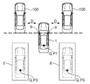
図12は、第1実施形態の図6に対応する図であり、縦列駐車に対する駐車支援開始時の所定の停止位置を示す。ここでは、左右両方向への縦列駐車に対する所定の停止位置が示されている。
乗員は駐車予定場所の前方や隣に駐車された駐車車両100など、駐車予定場所の端部を指定可能な場所で停車させる。具体的には、縦列駐車の場合には、図12に示すように、車両1のドアミラー9と、駐車予定場所の端部とが車両1の横方向に一直線となる位置で停車させる。車庫入れ駐車の場合には、上述した図7に示すように、車両1のドアミラー9と、駐車予定場所の端部とが車両1の横方向に一直線となる位置で停車させる。このとき、車両1は、駐車予定場所から横方向に所定の距離D離れた位置に停車される。これにより、車両1が水平面上に存在すると仮定した場合の、駐車予定場所と車両1との2次元座標上での関係が定まる。
FIG. 12 is a diagram corresponding to FIG. 6 of the first embodiment, and shows a predetermined stop position at the start of parking support for parallel parking. Here, a predetermined stop position for parallel parking in both the left and right directions is shown.
The occupant stops the end of the planned parking place such as the parked
上述したように駐車目標位置設定部23は、所定の停止位置において車両1の基準位置Qを基準として駐車目標位置P3や駐車目標エリアEを設定する。そして、誘導部29は図8及び図9に示すように支援開始位置P1から後退開始位置P2を経由して駐車目標位置P3に至る誘導経路を設定することができる。
但し、第1実施形態と同様に、車両1が所定の停止位置(支援開始位置P1)に停車した状態では、まだ、駐車形態は定まっていない。従って、車両1が所定の停止位置において停車し、駐車支援の開始指示が与えられた時点では、図13に示す全ての駐車目標位置P3及び駐車目標エリアEが仮設定される。即ち、車両1の右方向への車庫入れ駐車の場合の駐車目標位置p31、左方向への車庫入れ駐車の場合の駐車目標位置p32、車両1の左方向への縦列駐車の場合の駐車目標位置p33、及び車両1の右方向への縦列駐車の場合の駐車目標位置p34が、駐車目標位置P3として仮設定される。
As described above, the parking target
However, as in the first embodiment, in the state where the
駐車目標位置P3が仮設定されるまでの手順(図5#1〜#2)は、仮設定される数が4箇所となったことを除いて第1実施形態と同様である。また、駐車形態決定部25が、ステアリング4の操作量が所定の操作量A以上か否かを判定し(図5#3)、駐車形態が縦列駐車であるか、車庫入れ駐車であるかを決定する点も同様である。但し、ここで縦列駐車と判定された場合には、図5に示す処理#71へは進まない。第2実施形態では、$1の経路で図14のフローチャートへと移行し、縦列駐車に関する制御を実行した後、$2の経路で図5のフローチャートへと復帰する。車庫入れ駐車と判定された場合には、図5に示す処理#4を経て第1実施形態と同様の制御が実施されるのでここでは説明を省略する。
The procedure (FIG. 5 # 1 to # 2) until the parking target position P3 is temporarily set is the same as that in the first embodiment except that the temporarily set number is four. Further, the parking
以下、図14に基づいて縦列駐車と判定された場合の制御について説明する。処理#3において縦列駐車と判定されると、第1実施形態と同様に前進誘導が実施され(#81)、後退開始位置P2近傍で車両1が停止される。停止の方法や詳細な停止位置については第1実施形態と同様である。ここで、駐車形態決定部25は、スピーカ11を介して乗員にステアリング4の操作を促す。具体的には、右縦列駐車の場合にはステアリング4を右方向へ操作するように、左車庫入れの場合にはステアリング4を左方向へ操作するように音声で報知する。このとき、ステアリング4の操作量も定量的な数値で同時に報知される。縦列駐車の旋回における曲率は小さいため、この操作量は上述した前進誘導前の車庫入れ駐車に対する操作量よりも少ない量である。
Hereinafter, control when it is determined that parallel parking is performed based on FIG. 14 will be described. If it is determined in the
駐車形態決定部25は、ステアリング4の操作量が所定の操作量B以上か否かを判定し(#82)、駐車形態が左縦列駐車であるか否かを決定する。具体的には、ステアリング4の操作量が所定の操作量B未満の場合には第1実施形態と同様の初期値である左縦列駐車であると決定する(#84)。また、ステアリング4の操作量が所定の操作量B以上の場合には操作方向によって左縦列駐車であるか、右縦列駐車であるかを判定する(#83)。
駐車形態決定部25は、ステアリング4の操作量が左の場合には左縦列駐車であると決定し(#84)、操作方向が右の場合には右縦列駐車であると決定する(#87)。
そして、誘導部29は、スピーカ11を介して乗員にシフトレバー6をリバースに変更するように指示を発する(#85、#88)。乗員がシフトレバー6をリバースに変更してブレーキペダル8を緩めると、誘導部29は駐車目標位置P3までの後進誘導を開始する(#86、#89)。後進誘導の際には、第1実施形態と同様に、基準点Qが移動するものとして演算が実施される。
The parking
The parking
Then, the guiding
駐車形態の決定のタイミングは、基本的には、車両1が後退開始位置P2に達して停車した時点から所定時間経過後である。しかし、所定時間の経過を待たず、乗員がシフトレバー6をリバースに変更した時点で決定してもよい。
また、駐車形態の決定は、必ずしも、後退開始位置P2において車両1が完全に停止している状態で行われる必要はない。若干の移動を伴いながら決定されたり、若干の移動後の停止位置で決定されたりしてもよい。つまり、駐車形態の決定は、所定の停止位置の近傍で行われてもよい。
尚、処理#82においてステアリング4の操作量が所定の操作量B未満の場合に初期値の左縦列駐車と判定され、処理#84において決定されることについて上述した。従って、例えば、後退開始位置P2においてステアリング4が操作されずにシフトレバー6が変更され、ブレーキペダル8が緩められて車両1が発進した場合には、左縦列駐車と決定してもよい。この場合には、ほぼ第1実施形態と同様の縦列駐車制御が行われることとなる。
The timing for determining the parking mode is basically after a predetermined time has elapsed since the
Further, the determination of the parking mode is not necessarily performed in a state where the
As described above, it is determined that the left column parking is the initial value when the operation amount of the
〔第3実施形態〕
上記第1実施形態及び第2実施形態においては、自動操舵により駐車を支援する駐車支援装置に本発明を適用して説明した。しかし、手動操舵による駐車支援装置にも勿論本発明を適用することができる。図15〜図17は、手動操舵による駐車支援装置に本発明を適用する場合の実施形態の一例である。
図15は、第3実施形態に係る車両の斜視図である。車両1の前端及び後端にはカメラ12が備えられている。カメラ12はCCD(charge coupled device)やCIS(CMOS image sensor)などの撮像素子を内蔵するとともに、撮影した情報を動画情報として出力するデジタルカメラである。カメラ12は車両1の前方や後方に向けてやや俯角を有して設置されている。尚、夫々のカメラは、リアルタイムで動画を出力する性能を有するものである。
[Third Embodiment]
In the said 1st Embodiment and 2nd Embodiment, it applied and demonstrated this invention to the parking assistance apparatus which assists parking by automatic steering. However, the present invention can of course be applied to a parking assist device by manual steering. 15 to 17 show an example of an embodiment in which the present invention is applied to a parking assist device by manual steering.
FIG. 15 is a perspective view of a vehicle according to the third embodiment.
図16は、本実施形態に係る駐車支援装置の構成を模式的に示すブロック図である。図に示すように、カメラ12を含んで入力系が形成される。また、カメラ12による撮影画像が表示されるモニタ10を含んで出力系が形成される。また、ECU20は、重畳部28を有して構成されており、モニタ10には重畳部28によって撮影画像にガイド情報が重畳されて表示される。
FIG. 16 is a block diagram schematically showing the configuration of the parking assistance apparatus according to the present embodiment. As shown in the figure, an input system including a
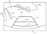
図17は、撮影画像にガイド情報が重畳された表示の一例を示す図である。これは、後方に向けて設置されたカメラ12により撮影された画像に、ガイド線Y1、Y2、Y3、Rが重畳された例である。撮影画像の下方には車両1の後部バンパーが映っている。本例では、駐車枠線Wに挟まれた駐車目標エリアEに車両1を駐車させる。例えば、ガイド線Y1及びY2は車幅延長線、ガイド線Y2は後方5m目安線、ガイド線Y3は後方3m目安線、ガイド線Rは後方1m注意線である。
FIG. 17 is a diagram illustrating an example of a display in which guide information is superimposed on a captured image. This is an example in which guide lines Y1, Y2, Y3, and R are superimposed on an image photographed by the
このようにして目視可能な駐車ガイドを用いて駐車を支援する駐車支援装置においても、多くの場合、駐車支援の開始時には駐車形態を決定して駐車目標を設定する必要がある。従来はタッチパネル10Tなどの指示入力手段を用いて駐車形態が入力されていた。しかし、本発明を適用すれば、運転中に乗員が操作するステアリング4を用いて良好に駐車形態を設定することができる。
Even in a parking assist device that assists parking using a visually visible parking guide in this manner, it is necessary to determine a parking mode and set a parking target at the start of parking assist. Conventionally, the parking mode has been input using instruction input means such as the
以上、多数の実施形態を用いて説明したように、本発明によって簡単な方法で駐車形態を指示することができる利便性の高い駐車支援装置を提供することができる。尚、当業者であれば、上記実施形態の一部を改変して本発明を構成することが容易である。しかし、そのような改変もまた、本発明の技術的範囲に属するものであることは言うまでもない。 As described above, as described using a number of embodiments, the present invention can provide a highly convenient parking assistance device that can instruct a parking mode by a simple method. A person skilled in the art can easily configure the present invention by modifying a part of the above embodiment. However, it goes without saying that such modifications also belong to the technical scope of the present invention.
1:車両
4:ステアリング(指示入力手段、中止入力手段)
23:駐車目標位置設定部
25:駐車形態決定部
27:移動状態検出部
29:誘導部
P1:支援開始位置(所定の停止位置)
P2:後退開始位置
P3、p31、p32、p33、p34:駐車目標位置
1: Vehicle 4: Steering (instruction input means, stop input means)
23: Parking target position setting unit 25: Parking mode determination unit 27: Movement state detection unit 29: Guide unit P1: Support start position (predetermined stop position)
P2: Reverse start position P3, p31, p32, p33, p34: Parking target position
Claims (6)
所定の停止位置において前記車両の駐車目標位置を駐車形態ごとに仮設定する駐車目標位置設定部と、
前記駐車目標位置の設定後、乗員によるステアリングの操作に基づいて、前記駐車形態及び当該駐車形態に対応する前記駐車目標位置を決定する駐車形態決定部と、
前記駐車目標位置へ前記車両を誘導する誘導部と、を備える駐車支援装置。 A parking assistance device that assists in parking a vehicle,
A parking target position setting unit that temporarily sets the parking target position of the vehicle for each parking mode at a predetermined stop position;
After the setting of the parking target position, based on the steering operation by the occupant, the parking mode determining unit that determines the parking mode and the parking target position corresponding to the parking mode;
A parking support apparatus comprising: a guiding unit that guides the vehicle to the parking target position.
前記駐車形態決定部は、前記車両が前記後退開始位置へ到達した後、前記後退開始位置の近傍において前記ステアリングが、所定の操作量以上右回りに操作された場合に、前記駐車形態が右縦列駐車であると決定し、所定の操作量以上左回りに操作された場合に、前記駐車形態が左縦列駐車であると決定する請求項1〜3の何れか一項に記載の駐車支援装置。 The guide section guides the vehicle to the parking target position behind the reverse start position after guiding the vehicle to the reverse start position ahead of the predetermined stop position,
When the steering is operated clockwise more than a predetermined operation amount in the vicinity of the reverse start position after the vehicle has reached the reverse start position, the parking type determination unit determines that the parking type is a right column. The parking assistance device according to any one of claims 1 to 3, wherein it is determined that the parking is performed, and the parking mode is determined to be left parallel parking when the vehicle is operated counterclockwise by a predetermined operation amount or more.
前記ステアリングは、
前記駐車支援の開始後、前記自動操舵制御の開始前において前記駐車形態決定部に対する前記駐車形態の指示入力手段であり、
前記自動操舵制御の開始後、前記自動操舵の完了前において前記誘導部に対する前記自動操舵制御の中止入力手段である、請求項1〜5の何れか一項に記載の駐車支援装置。 The guide unit is for automatically steering the vehicle to the parking target position via the reverse start position,
The steering is
The parking mode instruction input means for the parking mode determination unit before the start of the automatic steering control after the start of the parking support,
The parking assist device according to any one of claims 1 to 5, wherein the parking assist device is a stop input unit for the automatic steering control with respect to the guidance unit after the automatic steering control is started and before the automatic steering is completed.
Priority Applications (5)
| Application Number | Priority Date | Filing Date | Title |
|---|---|---|---|
| JP2007042513A JP4635017B2 (en) | 2007-02-22 | 2007-02-22 | Parking assistance device |
| EP08711478.1A EP2113426B1 (en) | 2007-02-22 | 2008-02-18 | Parking assist apparatus |
| CN2008800058838A CN101622158B (en) | 2007-02-22 | 2008-02-18 | Parking assistance device |
| PCT/JP2008/052654 WO2008102726A1 (en) | 2007-02-22 | 2008-02-18 | Parking assistance device |
| US12/528,161 US8275518B2 (en) | 2007-02-22 | 2008-02-18 | Parking assist apparatus |
Applications Claiming Priority (1)
| Application Number | Priority Date | Filing Date | Title |
|---|---|---|---|
| JP2007042513A JP4635017B2 (en) | 2007-02-22 | 2007-02-22 | Parking assistance device |
Publications (2)
| Publication Number | Publication Date |
|---|---|
| JP2008201363A JP2008201363A (en) | 2008-09-04 |
| JP4635017B2 true JP4635017B2 (en) | 2011-02-16 |
Family
ID=39710003
Family Applications (1)
| Application Number | Title | Priority Date | Filing Date |
|---|---|---|---|
| JP2007042513A Active JP4635017B2 (en) | 2007-02-22 | 2007-02-22 | Parking assistance device |
Country Status (5)
| Country | Link |
|---|---|
| US (1) | US8275518B2 (en) |
| EP (1) | EP2113426B1 (en) |
| JP (1) | JP4635017B2 (en) |
| CN (1) | CN101622158B (en) |
| WO (1) | WO2008102726A1 (en) |
Families Citing this family (29)
| Publication number | Priority date | Publication date | Assignee | Title |
|---|---|---|---|---|
| JP5332657B2 (en) * | 2009-01-29 | 2013-11-06 | 日産自動車株式会社 | Parking operation support device and parking operation support method |
| JP5403330B2 (en) | 2009-02-25 | 2014-01-29 | アイシン精機株式会社 | Parking assistance device |
| JP5257689B2 (en) * | 2009-03-11 | 2013-08-07 | アイシン精機株式会社 | Parking assistance device |
| JP5605000B2 (en) * | 2010-06-09 | 2014-10-15 | 日産自動車株式会社 | Parking assistance device and parking assistance method |
| RU2523861C1 (en) * | 2010-06-09 | 2014-07-27 | Ниссан Мотор Ко., Лтд. | Parking mode selection device and method |
| JP5440867B2 (en) | 2010-06-18 | 2014-03-12 | アイシン精機株式会社 | Parking assistance device |
| JP5099195B2 (en) * | 2010-09-24 | 2012-12-12 | 株式会社デンソー | Reverse parking assist device for vehicle and program for reverse parking assist device |
| JP5982750B2 (en) * | 2011-08-04 | 2016-08-31 | 日産自動車株式会社 | Parking assistance device and parking assistance method |
| JP5803426B2 (en) * | 2011-08-23 | 2015-11-04 | 日産自動車株式会社 | Parking assistance device |
| DE102011112578A1 (en) * | 2011-09-08 | 2013-03-14 | Continental Teves Ag & Co. Ohg | Method and device for an assistance system in a vehicle for carrying out an autonomous or semi-autonomous driving maneuver |
| KR101305630B1 (en) * | 2011-09-30 | 2013-09-09 | 현대자동차주식회사 | Parking Assist System for varying parking lot and method thereof |
| KR101918666B1 (en) * | 2012-04-03 | 2018-11-14 | 현대모비스 주식회사 | Steering automatic centering device having speech control and conrol method thereof |
| JP5906999B2 (en) * | 2012-08-24 | 2016-04-20 | 株式会社デンソー | Parking assistance device |
| US9213102B2 (en) | 2013-09-11 | 2015-12-15 | Google Technology Holdings LLC | Electronic device with gesture detection system and methods for using the gesture detection system |
| JP6167824B2 (en) * | 2013-10-04 | 2017-07-26 | アイシン精機株式会社 | Parking assistance device |
| KR101498973B1 (en) * | 2013-11-21 | 2015-03-05 | 현대모비스(주) | Parking asistance system and parking asistance method |
| KR102169263B1 (en) * | 2014-05-13 | 2020-10-23 | 주식회사 만도 | Parking out control system and method thereof |
| DE102014209227B4 (en) * | 2014-05-15 | 2022-03-17 | Ford Global Technologies, Llc | parking assistance system |
| JP6562709B2 (en) * | 2015-05-14 | 2019-08-21 | 株式会社デンソーテン | Parking assistance device and parking assistance method |
| DE102015211754A1 (en) * | 2015-06-24 | 2016-12-29 | Bayerische Motoren Werke Aktiengesellschaft | Parking assistance system for the automated carrying out of a parking maneuver in a transverse parking space with detection of a bottom parking space bounding the rear parking space obstacle |
| DE102015213172A1 (en) * | 2015-07-14 | 2017-01-19 | Robert Bosch Gmbh | Method and device for driver assistance |
| JP2017140890A (en) * | 2016-02-09 | 2017-08-17 | ソニー株式会社 | Information processing apparatus, information processing method, and program |
| JP7142050B2 (en) * | 2020-03-18 | 2022-09-26 | 本田技研工業株式会社 | PARKING ASSIST SYSTEM, PARKING ASSIST DEVICE, AND VEHICLE |
| JP7448394B2 (en) * | 2020-03-26 | 2024-03-12 | 本田技研工業株式会社 | parking assistance system |
| CN113421382B (en) * | 2021-06-01 | 2022-08-30 | 杭州鸿泉物联网技术股份有限公司 | Detection method, system, equipment and storage medium for shared electric bill standard parking |
| KR20240014764A (en) * | 2022-07-26 | 2024-02-02 | 현대자동차주식회사 | Apparatus, method and computer readable storage medium for recording image in vehicle parking at neutral parking mode |
| US12344235B2 (en) | 2022-10-28 | 2025-07-01 | Panasonic Automotive Systems Co., Ltd. | Parking support apparatus and parking support method |
| CN115742963A (en) * | 2022-12-28 | 2023-03-07 | 深圳纵目安驰科技有限公司 | Auxiliary system for guiding vehicle to back up and enter garage |
| JP7782501B2 (en) * | 2023-04-06 | 2025-12-09 | トヨタ自動車株式会社 | Automatic parking control device |
Family Cites Families (18)
| Publication number | Priority date | Publication date | Assignee | Title |
|---|---|---|---|---|
| JP3683091B2 (en) | 1997-04-15 | 2005-08-17 | 本田技研工業株式会社 | Automatic vehicle steering system |
| JP3881775B2 (en) * | 1998-05-15 | 2007-02-14 | 本田技研工業株式会社 | Automatic vehicle steering system |
| JP3951465B2 (en) * | 1998-06-26 | 2007-08-01 | アイシン精機株式会社 | Parking assistance device |
| JP4723703B2 (en) | 1999-06-25 | 2011-07-13 | 富士通テン株式会社 | Vehicle driving support device |
| US7366595B1 (en) | 1999-06-25 | 2008-04-29 | Seiko Epson Corporation | Vehicle drive assist system |
| DE60139236D1 (en) * | 2000-05-12 | 2009-08-27 | Toyota Jidoshokki Kariya Kk | HELP REVERSE A VEHICLE |
| US6825828B2 (en) * | 2001-02-23 | 2004-11-30 | General Digital Corporation | Backlit LCD monitor |
| JP3917008B2 (en) | 2002-05-30 | 2007-05-23 | 株式会社ジェイテクト | Automatic steering control device |
| JP2004009791A (en) * | 2002-06-04 | 2004-01-15 | Mitsubishi Motors Corp | Parking assistance device |
| US7085634B2 (en) * | 2003-04-11 | 2006-08-01 | Toyota Jidosha Kabushiki Kaisha | Parking assist apparatus and parking assist method for vehicle |
| JP3883529B2 (en) | 2003-08-28 | 2007-02-21 | アイシン精機株式会社 | Vehicle reverse support device |
| JP2005313710A (en) * | 2004-04-27 | 2005-11-10 | Toyota Motor Corp | Parking assistance device |
| JP4491671B2 (en) | 2005-02-07 | 2010-06-30 | 株式会社豊田自動織機 | Parking assistance device |
| JP4188346B2 (en) | 2005-07-13 | 2008-11-26 | 本田技研工業株式会社 | Vehicle steering device |
| JP4414959B2 (en) * | 2005-11-16 | 2010-02-17 | アイシン精機株式会社 | Parking assistance device |
| EP1950098A1 (en) * | 2005-11-17 | 2008-07-30 | Aisin Seiki Kabushiki Kaisha | Parking assisting device and parking assisting method |
| JP4725796B2 (en) * | 2006-06-13 | 2011-07-13 | 株式会社ジェイテクト | Vehicle steering system |
| US20080154464A1 (en) * | 2006-12-26 | 2008-06-26 | Honda Motor Co., Ltd. | Automatic Parking control apparatus for vehicle |
-
2007
- 2007-02-22 JP JP2007042513A patent/JP4635017B2/en active Active
-
2008
- 2008-02-18 EP EP08711478.1A patent/EP2113426B1/en not_active Not-in-force
- 2008-02-18 US US12/528,161 patent/US8275518B2/en active Active
- 2008-02-18 WO PCT/JP2008/052654 patent/WO2008102726A1/en not_active Ceased
- 2008-02-18 CN CN2008800058838A patent/CN101622158B/en not_active Expired - Fee Related
Also Published As
| Publication number | Publication date |
|---|---|
| EP2113426A4 (en) | 2012-11-14 |
| WO2008102726A1 (en) | 2008-08-28 |
| JP2008201363A (en) | 2008-09-04 |
| CN101622158B (en) | 2011-08-10 |
| US20100049401A1 (en) | 2010-02-25 |
| EP2113426B1 (en) | 2014-12-03 |
| EP2113426A1 (en) | 2009-11-04 |
| CN101622158A (en) | 2010-01-06 |
| US8275518B2 (en) | 2012-09-25 |
Similar Documents
| Publication | Publication Date | Title |
|---|---|---|
| JP4635017B2 (en) | Parking assistance device | |
| JP5115782B2 (en) | Parking assistance device | |
| JP5105149B2 (en) | Parking assistance device | |
| EP2402220B1 (en) | Parking assistance device | |
| JP4853712B2 (en) | Parking assistance device | |
| US7825828B2 (en) | Parking assist device | |
| JP5429514B2 (en) | Parking assistance device | |
| JP3936204B2 (en) | Parking assistance device | |
| JP5262368B2 (en) | Parking assistance device and parking assistance method | |
| JP2010202010A (en) | Parking support device | |
| CN102405154A (en) | parking aid | |
| WO2009136559A1 (en) | Vehicle peripheral display device | |
| JP6788439B2 (en) | Delivery support device | |
| CN107791950B (en) | Outbound auxiliary device | |
| JP6373916B2 (en) | Parking exit support device | |
| JP5212755B2 (en) | Parking assistance device | |
| JP4967604B2 (en) | Parking assistance system | |
| JP4790037B2 (en) | Parking assistance device | |
| JP4596254B2 (en) | Driving assistance device |
Legal Events
| Date | Code | Title | Description |
|---|---|---|---|
| A711 | Notification of change in applicant |
Free format text: JAPANESE INTERMEDIATE CODE: A711 Effective date: 20090116 |
|
| A521 | Request for written amendment filed |
Free format text: JAPANESE INTERMEDIATE CODE: A821 Effective date: 20090116 |
|
| TRDD | Decision of grant or rejection written | ||
| A01 | Written decision to grant a patent or to grant a registration (utility model) |
Free format text: JAPANESE INTERMEDIATE CODE: A01 Effective date: 20101111 |
|
| A01 | Written decision to grant a patent or to grant a registration (utility model) |
Free format text: JAPANESE INTERMEDIATE CODE: A01 |
|
| A61 | First payment of annual fees (during grant procedure) |
Free format text: JAPANESE INTERMEDIATE CODE: A61 Effective date: 20101119 |
|
| R151 | Written notification of patent or utility model registration |
Ref document number: 4635017 Country of ref document: JP Free format text: JAPANESE INTERMEDIATE CODE: R151 |
|
| FPAY | Renewal fee payment (event date is renewal date of database) |
Free format text: PAYMENT UNTIL: 20131126 Year of fee payment: 3 |
