JP5605000B2 - Parking assistance device and parking assistance method - Google Patents
Parking assistance device and parking assistance method Download PDFInfo
- Publication number
- JP5605000B2 JP5605000B2 JP2010132042A JP2010132042A JP5605000B2 JP 5605000 B2 JP5605000 B2 JP 5605000B2 JP 2010132042 A JP2010132042 A JP 2010132042A JP 2010132042 A JP2010132042 A JP 2010132042A JP 5605000 B2 JP5605000 B2 JP 5605000B2
- Authority
- JP
- Japan
- Prior art keywords
- parking
- target position
- image
- parking target
- temporary
- Prior art date
- Legal status (The legal status is an assumption and is not a legal conclusion. Google has not performed a legal analysis and makes no representation as to the accuracy of the status listed.)
- Active
Links
Images


Landscapes
- Closed-Circuit Television Systems (AREA)
- Traffic Control Systems (AREA)
Description
本発明は、自車両の周囲の映像を運転者に提示して駐車を支援する駐車支援装置及びその方法に関する。 The present invention relates to a parking assistance apparatus and method for assisting parking by presenting a video around a host vehicle to a driver.
従来から所定の駐車目標位置へ車両を駐車させるための駐車支援装置が開発されており、このような駐車支援装置の一例として特許文献1が開示されていた。 Conventionally, a parking assistance device for parking a vehicle at a predetermined parking target position has been developed, and Patent Document 1 has been disclosed as an example of such a parking assistance device.
特許文献1に開示された駐車支援装置では、自車両を所定の停止位置に停車させた状態で、複数の駐車目標位置を駐車形態ごとに仮設定して運転者に提示している。すなわち、自車両の右方向への並列駐車、左方向への並列駐車及び左方向への縦列駐車などの駐車目標位置を仮設定して運転者に提示していた。 In the parking assistance device disclosed in Patent Document 1, a plurality of parking target positions are temporarily set for each parking mode and presented to the driver while the host vehicle is stopped at a predetermined stop position. That is, parking target positions such as parallel parking in the right direction of the host vehicle, parallel parking in the left direction, and parallel parking in the left direction are temporarily set and presented to the driver.
運転者は、こうして仮設定された駐車目標位置の中からステアリング操作によって駐車目標位置を選択し、駐車支援装置は選択された駐車目標位置へ車両を誘導していた。 The driver selects a parking target position by steering operation from the temporarily set parking target positions in this way, and the parking assist device guides the vehicle to the selected parking target position.
しかしながら、上述した従来の駐車支援装置では、駐車目標位置を認識するために画像認識を用いていたため、CPUの演算量が増大してシステム全体の価格が高価になってしまうという問題点があった。また、画像認識を用いると、画像認識で検出した駐車枠を微調整する場合に画面もしくはボタンを連続的に押し続ける作業が発生するので、駐車目標枠を指定する際に多くの手間がかかってしまうという問題点もあった。さらに、白線が引かれていない駐車場に駐車する場合には、画像認識では駐車支援を行うこと自体が不可能であった。 However, in the above-described conventional parking assist device, since image recognition is used to recognize the parking target position, there is a problem that the amount of calculation of the CPU increases and the price of the entire system becomes expensive. . In addition, when image recognition is used, when finely adjusting the parking frame detected by image recognition, the work of continuously pressing the screen or button occurs, so it takes a lot of time to specify the parking target frame. There was also a problem of end. Further, when parking in a parking lot where no white line is drawn, it is impossible to perform parking support by image recognition.
そこで、本発明は、上述した実情に鑑みて提案されたものであり、画像認識を用いることなく駐車目標位置を運転者に提示することによって、安価にシステムを構成することのできる駐車支援装置及びその方法を提供することを目的とする。 Therefore, the present invention has been proposed in view of the above-described circumstances, and provides a parking assistance device capable of configuring a system at low cost by presenting a parking target position to a driver without using image recognition. An object is to provide such a method.
本発明に係る駐車支援装置は、自車両周囲の俯瞰映像に予め用意された仮駐車目標位置の画像を重畳して表示し、俯瞰映像に表示されている実際の駐車目標位置に仮駐車目標位置の画像が一致するように運転者によって自車両の移動が行われた後に、運転者が駐車目標位置を指定し、指定された駐車目標位置へ自車両を誘導制御することによって上述の課題を解決する。 The parking assist device according to the present invention superimposes and displays an image of a provisional parking target position prepared in advance on a bird's-eye view around the host vehicle, and places the temporary parking target position on the actual parking target position displayed in the bird's-eye view image. After the driver moves the vehicle so that the images match, the driver specifies the parking target position, and guides and controls the vehicle to the specified parking target position. To do.
本発明に係る駐車支援装置及びその方法によれば、予め用意された仮駐車目標位置の画像を俯瞰映像に重畳して表示し、俯瞰映像に表示されている実際の駐車目標位置に仮駐車目標位置の画像が一致するように運転者によって自車両の移動が行われた後に、運転者が駐車目標位置を指定するので、画像認識等を用いることなく駐車目標位置を指定することができる。これによって、CPUの演算量を低減することができるので、安価にシステムを構成することができる。 According to the parking assist device and the method thereof according to the present invention, an image of a provisional parking target position prepared in advance is displayed superimposed on the overhead video, and the temporary parking target is displayed at the actual parking target position displayed in the overhead video. Since the driver designates the parking target position after the driver moves the vehicle so that the images of the positions coincide with each other, the parking target position can be designated without using image recognition or the like. As a result, the calculation amount of the CPU can be reduced, and the system can be configured at low cost.
以下、本発明の第1乃至第4実施形態について図面を参照して説明する。 Hereinafter, first to fourth embodiments of the present invention will be described with reference to the drawings.
[第1実施形態]
[駐車支援装置の構成]
本発明を適用した第1実施形態について図面を参照して説明する。図1は本実施形態に係る駐車支援装置の構成を示すブロック図である。
[First Embodiment]
[Configuration of parking assist device]
A first embodiment to which the present invention is applied will be described with reference to the drawings. FIG. 1 is a block diagram showing the configuration of the parking assistance apparatus according to the present embodiment.
図1に示すように、本実施形態に係る駐車支援装置1は、自車両周囲の映像を変換して俯瞰映像を生成する俯瞰映像生成部2と、運転者から駐車支援装置への操作が入力される入力部3と、仮駐車目標位置の画像を俯瞰映像に重畳して表示するための設定を行う仮駐車目標位置設定部4と、仮駐車目標位置の画像を俯瞰映像に重畳する画像重畳部5と、運転者によって駐車目標位置が指定される駐車目標位置指定部6と、指定された駐車目標位置へ自車両を誘導制御する駐車誘導制御部7とを備え、自車両周囲の映像を撮像するカメラ8a〜8dと、運転者に映像を提示する表示部9と、ステアリングホイールの操作方向及び操作量を検出する舵角センサ10と、パワーステアリングを駆動するEPSモータ11と接続されている。
As shown in FIG. 1, the parking assistance device 1 according to the present embodiment receives an overhead
ここで、上述した駐車支援装置1は、例えば図示していないROM(Read Only Memory)に駐車支援プログラムを記憶しておき、この駐車支援プログラムをCPUで実行することによって実現することができる。 Here, the parking assistance device 1 described above can be realized by, for example, storing a parking assistance program in a ROM (Read Only Memory) (not shown) and executing the parking assistance program by the CPU.
入力部3は、運転者からの入力を受け付けるインターフェース部であり、例えば2つのボタンを用意して一方のボタンを選択ボタン、他方のボタンを決定ボタンとして割り付けることによって、システム側からのプロンプトに応じた運転者の意思表示が可能となるように形成されている。 The input unit 3 is an interface unit that receives input from the driver. For example, by preparing two buttons and assigning one button as a selection button and the other button as a determination button, the input unit 3 responds to a prompt from the system side. It is formed so that the driver's intention can be expressed.
カメラ8a〜8dは、自車両周囲の映像を撮像するための撮像手段であり、駐車支援装置1と運転者との間のインターフェースとして使用される画像を取得している。ここで、図2にカメラ8a〜8dの配置の一例を示す。図2に示すように車両20のフロントグリル部にカメラ8aを配置し、リアバンパ近傍にカメラ8dを配置し、左右のドアミラーの下部にカメラ8b及び8cを配置している。カメラ8a〜8dは視野角の広い広角カメラを使用することによって、より広い領域を運転者に提示することができる。なお、車両20は乗用車に限らず、商用車や貨物自動車でもあってもよい。また、カメラ8a〜8dの設置位置は図2に示す配置に限定されるわけではなく、例えば車両の四隅に設置する形態やルーフに設置する形態を採用してもよい。
The
俯瞰映像生成部2は、カメラ8a〜8dで撮像した映像に対して視点変換を行って俯瞰映像を生成する。カメラ8a〜8dで撮像した映像は斜め上に視点が置かれた映像であるが、この映像に対して視点変換を行うことによって地面に対して鉛直上方から見た映像を得ることができる。ここで行われる画像変換に関しては、例えば「鈴木政康・知野見聡・高野照久,俯瞰ビューシステムの開発,自動車技術会学術講演会前刷集,116-07(2007-10), 17-22.」などに記載された方法を用いればよい。
The overhead view
仮駐車目標位置設定部4は、仮の駐車目標位置である仮駐車目標位置の画像を予め用意しておき、入力部3で入力された運転者の意思の検出信号に基づいて仮駐車目標位置の画像を俯瞰映像に重畳するための設定を行う。例えば、予めメモリなどに格納されている仮駐車目標位置の画像を読み込んでくるだけでもよいし、または読み込まれた仮駐車目標位置の画像の大きさを変更したり、色や明るさを変更したりしてもよい。
The temporary parking target
画像重畳部5は、俯瞰映像生成部2で生成された自車両周囲の俯瞰映像に、仮駐車目標位置の画像を重畳する。ここで行われる画像の重畳はコンピュータグラフィクスのスーパーインポーズの手法を用いて行うことができる。
The
表示部9は、画像重畳部5で得られた画像を運転者に視覚情報として提示するための表示手段であり、例えばカーナビゲーションシステムのモニタなどである。
The display unit 9 is a display unit for presenting the image obtained by the
駐車目標位置指定部6は、入力部3に設けられており、俯瞰映像に表示されている実際の駐車目標位置に仮駐車目標位置の画像が一致するように自車両の移動が行われた後に、実際の駐車目標位置に対応した仮駐車目標位置を、運転者が駐車目標位置として指定する入力を受け付ける。また、ここで指定された駐車目標位置は駐車誘導制御部7に送信される。 The parking target position specifying unit 6 is provided in the input unit 3, and after the host vehicle is moved so that the image of the temporary parking target position matches the actual parking target position displayed in the overhead view video. The driver receives an input for designating the temporary parking target position corresponding to the actual parking target position as the parking target position. Further, the parking target position designated here is transmitted to the parking guidance control unit 7.
舵角センサ10は、ステアリングホイールに取り付けられてステアリングホイールの操作量及び操作方向を検出して駐車誘導制御部7へ送信している。
The
駐車誘導制御部7は、舵角センサ10で検出された値をフィードバックしながら駐車目標位置指定部6で指定された駐車目標位置へ自車両を誘導制御する制御指令信号を計算している。そして、得られた制御指令信号をEPSモータ11に入力している。
The parking guidance control unit 7 calculates a control command signal for guiding and controlling the host vehicle to the parking target position designated by the parking target position designating unit 6 while feeding back the value detected by the
EPSモータ11は、駐車誘導制御部7からの制御指令信号に基づいて、パワーステアリングを駆動して、自車両が目標駐車位置へ駐車できるように操作している。 The EPS motor 11 operates the power steering based on a control command signal from the parking guidance control unit 7 so that the host vehicle can park at the target parking position.
[駐車支援装置の動作]
次に、本実施形態に係る駐車支援装置1による駐車支援処理を図3のフローチャートを参照して説明する。図3に示す駐車支援処理のアルゴリズムはタイマ割り込みによって実施され、予め設定したサンプリング時間ごとに行うことによって駐車支援処理が実施されている。
[Operation of parking assist device]
Next, parking assistance processing by the parking assistance apparatus 1 according to the present embodiment will be described with reference to the flowchart of FIG. The algorithm of the parking assistance process shown in FIG. 3 is implemented by timer interruption, and the parking assistance process is implemented by performing it every preset sampling time.
図3に示すように、ステップS101において、カメラ8a〜8dで自車両周囲の映像を撮像し、撮像された映像を俯瞰映像生成部2に送信する。
As shown in FIG. 3, in step S <b> 101, images around the host vehicle are captured by the
次にステップS102において、俯瞰映像生成部2はカメラ8a〜8dで撮像された自車両周囲の映像に対して視点変換を行い、自車両周囲の俯瞰映像を生成する。ここで、俯瞰映像生成部2で生成された俯瞰映像の一例を図4に示す。図4に示すように、自車両の位置を示すコンピュータグラフィックス40を中心部に配置し、その周囲4方向に視点変換された映像41a〜41dを並べて表示することによって俯瞰映像42を構成する。映像41aはカメラ8aで撮像された自車両前方の映像を視点変換したものであり、映像41b、41cはカメラ8b、8cで撮像された自車両左右の映像を視点変換したものであり、映像41dはカメラ8dで撮像された自車両後方の映像を視点変換したものである。尚、俯瞰映像42において4方向全ての映像が完全に表示されている必要はなく、例えば横方向に対応する映像41b、41cのみを俯瞰映像42に表示し、前後方向の映像はカメラ8a、8dで撮像した映像自体を表示するという形態も可能である。
Next, in step S102, the bird's-eye view
こうして俯瞰映像が生成されると、ステップS103では運転者からの駐車支援開始信号が入力部3に入力されたか否かを判定する。運転者によって開始ボタンが押下されるなどして駐車支援開始信号を検知した場合にはステップS104に移行し、検知しない場合には駐車支援を行わないものと判断して終了する。 When the bird's-eye view video is generated in this way, in step S103, it is determined whether or not a parking assistance start signal from the driver is input to the input unit 3. If a parking support start signal is detected by the driver pressing the start button or the like, the process proceeds to step S104, and if not detected, it is determined that parking support is not performed and the process ends.
ステップS104では、仮駐車目標位置設定部4によって仮駐車目標位置の画像を設定する。例えば、予めメモリ内に格納されている仮駐車目標位置の画像を読み込んで用意するだけでもよいし、または読み込まれた仮駐車目標位置の画像の大きさを変更したり、色や明るさを変更したりしてもよい。
In step S104, the temporary parking target
ここで、本実施形態に係る仮駐車目標位置の画像を図5に示す。図5に示すように、本実施形態では自車両の位置を示すコンピュータグラフィックス50を中心部に配置し、その左右に鉤型の印を描くことによって仮駐車目標位置を表現している。図5に示す仮駐車目標位置の画像のうちマーク52a及びマーク52bの2つの鉤型は左側の並列駐車に対応した仮駐車目標位置の画像を示している。マーク53a及びマーク53bの2つの斜め向き線分は左側斜め45度の斜め駐車に対応した仮駐車目標位置の画像を示している。マーク54a及びマーク54bの2つの鉤型は左側の縦列駐車に対応した仮駐車目標位置を示している。同様に、マーク55a及びマーク55bは右側の並列駐車枠に対応した仮駐車目標位置を示し、マーク56a及びマーク56bは右側の斜め駐車に対応した仮駐車目標位置を示し、マーク57a及びマーク57bは右側の縦列駐車に対応した仮駐車目標位置を示している。
Here, the image of the temporary parking target position which concerns on this embodiment is shown in FIG. As shown in FIG. 5, in this embodiment,
本実施形態では、左側の並列駐車に対応した仮駐車目標位置の画像52a、52bは、カメラ8cが設置されているドアミラーの位置を挟んで対称な位置に描画されている。このように描画することによって、カメラ8cの位置に近く、またカメラ8cから等距離に描画することになるので、カメラ8cの映像を俯瞰映像に変換した際に生じる映像の歪みを最小限に抑えることができる。斜め駐車に対応した仮駐車目標位置の画像53a、53bや右側についても同様である。
In the present embodiment, the
ただし、左側の縦列駐車に対応した仮駐車目標位置の画像54a、54bは自車両の後方に描画する。なぜなら、駐車支援が開始された後に駐車目標位置と切り返し位置を表示するが、縦列駐車の場合にはその軌道の特性から駐車目標位置を車両後方に設定しておかなければ、初期状態において切り返し位置を俯瞰映像内に表示することができないためである。そこで、本実施形態では縦列駐車に対応した仮駐車目標位置の画像54a、54bは車両後方になるように設定して、切り返し位置についても俯瞰映像内に表示できるようにしている。このように切り返し位置を俯瞰映像内に表示したことにより、駐車支援開始後に運転者がどこまで自車両を進めればよいか一目瞭然で理解できることになり、駐車支援が実施されている間の運転者の安心感を向上させることができる。尚、右側の縦列駐車についても同様である。
However, the
次にステップS105において、ステップS102で生成された俯瞰映像とステップS104で設定された仮駐車目標位置の画像とを、画像重畳部5で重畳して重畳画像を生成する。得られた重畳画像は表示部9に送られ、カーナビゲーションシステムのモニタなどに表示される。ここで重畳画像の一例を図6に示す。図6に示すように、自車両の位置を示すコンピュータグラフィックス60が中心部に配置され、その左右に鉤型の仮駐車目標位置が表示されている。
Next, in step S105, the overhead image generated in step S102 and the image of the temporary parking target position set in step S104 are superimposed by the
このようにして重畳画像が表示部10に表示されると、ステップS106において、運転者は重畳画像の表示を見ながら実際の駐車目標位置と仮駐車目標位置とがほぼ一致するように自車両を誘導して駐車支援開始位置を決定する。例えば、図6に示すように左側の並列駐車の場合には仮駐車目標位置62a、62bが実際の駐車目標位置61とほぼ一致するように自車両を誘導して駐車支援開始位置を決定する。この際、運転者による自車両の操舵、制動及び駆動操作によって自車両の誘導が行われる。なお、縦列駐車や斜め駐車の場合でも同様の操作を行うことによって、駐車支援開始位置へ自車両を誘導することができる。
When the superimposed image is displayed on the
このように、予め俯瞰映像上に重畳されている仮駐車目標位置と実際の駐車目標位置とを運転者が合わせることによって駐車開始位置を指定し、その開始位置を始点とした駐車経路をメモリから読み込んで駐車誘導制御を行うので、画像認識は必要なく、CPUの負荷を低減することができる。 In this way, the driver designates the parking start position by matching the temporary parking target position superimposed on the bird's-eye view image in advance with the actual parking target position, and the parking route starting from the start position is stored in the memory. Since parking guidance control is performed after reading, image recognition is not necessary, and the load on the CPU can be reduced.
次にステップS107では、運転者に並列駐車、縦列駐車、斜め駐車といった駐車形態の選択を促した後に、駐車目標位置指定部6を介して、重畳映像に表示されている仮駐車目標位置の中から実際の駐車目標位置に対応した仮駐車目標位置が指定されたか否かが判定される。ここで、決定ボタンが押下されて駐車目標位置が指定されると、ステップS108へ移行し、キャンセルボタンなどが押下されて駐車支援をキャンセルする意思表示がなされた場合には駐車支援処理を終了する。 Next, in step S107, after prompting the driver to select a parking mode such as parallel parking, parallel parking, and diagonal parking, through the parking target position designating unit 6, the temporary parking target position displayed in the superimposed image is displayed. It is determined whether a temporary parking target position corresponding to the actual parking target position is designated. Here, when the determination button is pressed and the parking target position is designated, the process proceeds to step S108, and when the cancel button or the like is pressed and an intention to cancel the parking support is displayed, the parking support process is ended. .
また、上述した仮駐車目標位置の画像について、駐車目標位置が指定される前は薄く表示しておき、駐車目標位置が指定された後には強調表示することも可能である。例えば、図7の駐車目標位置70に示すように、駐車目標位置が指定された後には駐車目標位置を実線で囲んで、さらに濃い色で強調表示するようにしてもよい。図8に示す縦列駐車の場合も同様である。このように表示することによって駐車誘導制御前は俯瞰映像の視認性を向上させることができ、駐車誘導制御時には駐車目標位置を運転者が明確に認識することができる。
Further, the image of the temporary parking target position described above can be displayed lightly before the parking target position is designated, and can be highlighted after the parking target position is designated. For example, as shown in the
駐車目標位置が指定されてステップS108に移行すると、指定された駐車目標位置に対応した駐車支援画像を表示部9の俯瞰映像上に重畳して表示する。例えば、左側の並列駐車の場合には図7に示すような駐車目標位置70と切り返し位置71がそれぞれ表示され、左側の縦列駐車の場合には図8に示すような駐車目標位置80と切り返し位置81がそれぞれ表示される。
When the parking target position is designated and the process proceeds to step S108, a parking support image corresponding to the designated parking target position is displayed superimposed on the overhead view video of the display unit 9. For example, a
次にステップS109において、駐車誘導制御部7による誘導制御が実施される。この誘導制御では制御ロジックにしたがって駐車支援が行われ、まず車両を誘導する経路が生成される。この誘導経路は並列駐車、縦列駐車、斜め駐車のそれぞれに対応した経路を1種類ずつメモリに保持しておき、指定された駐車目標位置に対応した経路を読み込むことによって実現することができる。この駐車誘導制御で計算される誘導経路は、切り返し位置までの曲線と切り替えし位置から駐車目標位置までの曲線である。 Next, in step S109, guidance control by the parking guidance control unit 7 is performed. In this guidance control, parking assistance is performed according to the control logic, and a route for guiding the vehicle is first generated. This guidance route can be realized by holding a route corresponding to each of parallel parking, parallel parking, and diagonal parking in the memory one by one and reading a route corresponding to the designated parking target position. The guidance route calculated by the parking guidance control is a curve from the position to the parking target position by switching to the curve to the turn-back position.
駐車誘導制御部7は、計算された誘導経路に追従するように舵角センサ10の値をフィードバックしながらパワーステアリングに設置してあるEPSモータ11への指令信号を計算する。算出された指令信号は逐次EPSモータ11に送信され、駐車誘導制御が実施される。この際、車両の制動及び駆動指令、前進及び後退の切り替え動作は運転者が行うものとする。
The parking guidance control unit 7 calculates a command signal to the EPS motor 11 installed in the power steering while feeding back the value of the
ただし、上述した駐車誘導制御だけではなく、例えば自車両が通ると予想される経路線をステアリング舵角および車速から計算して表示部9に重畳表示して運転者の転舵を支援及び誘導するだけでもよい。また、ステアリング転舵やブレーキ、アクセルのタイミングのみを知らせる誘導方法でも良い。 However, in addition to the above-described parking guidance control, for example, a route line expected to pass by the host vehicle is calculated from the steering angle and the vehicle speed and superimposed on the display unit 9 to assist and guide the driver's steering. Just be fine. Moreover, the guidance method which notifies only the timing of steering turning, a brake, and an accelerator may be used.
こうしてステップS109における駐車誘導制御が行われて駐車目標位置への駐車が完了すると、図3に示す駐車支援処理は終了する。 When the parking guidance control in step S109 is performed in this manner and the parking at the parking target position is completed, the parking support process shown in FIG. 3 ends.
[第1実施形態の効果]
以上詳細に説明したように、本発明を適用した第1実施形態に係る駐車支援装置によれば、予め用意された仮駐車目標位置の画像を俯瞰映像に重畳して表示し、俯瞰映像に表示されている実際の駐車目標位置に仮駐車目標位置の画像が一致するように運転者によって自車両の移動が行われた後に、運転者が駐車目標位置を指定するので、画像認識等を用いることなく駐車目標位置を指定することができる。これによって、CPUの演算量を低減することができるので、安価にシステムを構成することができる。また、目標駐車位置の微調整なども不要で、ひも等で仕切られた白線のない駐車場でも駐車支援が可能である。
[Effect of the first embodiment]
As described above in detail, according to the parking assistance apparatus according to the first embodiment to which the present invention is applied, an image of the provisional parking target position prepared in advance is displayed superimposed on the overhead video and displayed on the overhead video. Since the driver designates the parking target position after the driver has moved the vehicle so that the image of the temporary parking target position matches the actual parking target position, use image recognition or the like. It is possible to specify a parking target position. As a result, the calculation amount of the CPU can be reduced, and the system can be configured at low cost. In addition, fine adjustment of the target parking position is unnecessary, and parking assistance is possible even in a parking lot without white lines partitioned by strings or the like.
また、本駐車支援装置によれば、仮駐車目標位置の画像として並列駐車、縦列駐車、斜め駐車の駐車形態があるので、通常必要となる駐車形態のほとんどすべてに対応することができ、これによって運転者は駐車目標位置を容易に設定することができる。 In addition, according to the present parking assistance device, there are parallel parking, parallel parking, and diagonal parking parking modes as the image of the temporary parking target position, so that it is possible to cope with almost all of the parking modes normally required. The driver can easily set the parking target position.
さらに、本駐車支援装置によれば、並列駐車、斜め駐車を示す仮駐車目標位置の画像を自車両のドアミラーの位置に中心近傍が配置されるように俯瞰映像上に重畳するので、カメラの直下に仮駐車目標位置を設定することができ、これによって俯瞰映像の歪みを小さくすることができ、駐車支援の精度を向上させることができる。 Furthermore, according to the present parking assist device, the image of the temporary parking target position indicating parallel parking and oblique parking is superimposed on the overhead view image so that the vicinity of the center is arranged at the position of the door mirror of the own vehicle, so Thus, the temporary parking target position can be set, whereby the distortion of the overhead view image can be reduced, and the accuracy of parking support can be improved.
また、本駐車支援装置によれば、縦列駐車を示す仮駐車目標位置の画像を自車両のドアミラーの位置よりも後方になるように俯瞰映像上に重畳するので、切り返し位置を俯瞰映像上に表示することができ、駐車する際の軌道を運転者が理解しやすくなる。 In addition, according to the present parking assist device, the image of the temporary parking target position indicating parallel parking is superimposed on the overhead view image so as to be behind the position of the door mirror of the host vehicle, so the switching position is displayed on the overhead view image. This makes it easier for the driver to understand the trajectory when parking.
さらに、本駐車支援装置によれば、駐車目標位置が指定される前は仮駐車目標位置の画像を薄く表示し、駐車目標位置が指定された後には仮駐車目標位置の画像を強調表示するので、駐車誘導制御前は俯瞰映像の視認性を向上させることができ、駐車誘導制御時には駐車目標位置を運転者が明確に認識することができる。 Furthermore, according to the present parking assist device, the image of the temporary parking target position is displayed lightly before the parking target position is designated, and the image of the temporary parking target position is highlighted after the parking target position is designated. Before the parking guidance control, the visibility of the overhead view image can be improved, and the driver can clearly recognize the parking target position during the parking guidance control.
[第2の実施形態]
次に、本発明を適用した第2実施形態について図面を参照して説明する。尚、上述した第1実施形態と同様の部分については詳細な説明を省略する。
[Second Embodiment]
Next, a second embodiment to which the present invention is applied will be described with reference to the drawings. Detailed description of the same parts as those in the first embodiment described above will be omitted.
図9は第2実施形態に係る仮駐車目標位置の画像を示す図である。図9に示すように、第2実施形態に係る仮駐車目標位置の画像は、並列駐車、縦列駐車、斜め駐車を示すそれぞれの画像の一端が共有されている。 FIG. 9 is a diagram illustrating an image of the temporary parking target position according to the second embodiment. As shown in FIG. 9, as for the image of the temporary parking target position which concerns on 2nd Embodiment, the end of each image which shows parallel parking, parallel parking, and diagonal parking is shared.
例えば、鉤型のマーク92は左側の並列駐車と左側の縦列駐車に対応した仮駐車目標位置の前端を表していて共有されており、さらに左側の斜め駐車に対応した仮駐車目標位置の前端を表すマーク93aもマーク92と一端を共有している。また、線分のマーク93bは左側の斜め駐車に対応した仮駐車目標位置の後端であり、マーク92bは左側の並列駐車に対応した仮駐車目標位置の後端である。マーク94bは左側の縦列駐車に対応した仮駐車目標位置の後端である。尚、第1実施形態と同様に、並列駐車に対応した仮駐車目標位置の画像92、92bは、その中心がドアミラーの位置となるように配置されている。同様に、マーク95、95b、96a、96b、97bはそれぞれ右側駐車に対応した仮駐車目標位置の画像であり、左側の仮駐車目標位置の画像と対称な位置に表示されている。
For example, the saddle-shaped
また、第2実施形態に係る駐車支援装置では、鉤型のマーク98a〜98dをさらに表示している。このマーク98a〜98dは駐車時に自車両が通過可能な領域を示すクリアランス領域を示しており、仮駐車目標位置の画像の外側に設定されている。例えば、マーク98aが示す領域の下側に障害物があった場合には、左側の並列駐車時に障害物に衝突する恐れがあることを示している。
Moreover, in the parking assistance apparatus according to the second embodiment, saddle-shaped
[第2実施形態の効果]
以上詳細に説明したように、本発明を適用した第2実施形態に係る駐車支援装置によれば、並列駐車、縦列駐車、斜め駐車を示す仮駐車目標位置の画像の一端を共通化したので、仮駐車目標位置を示す線が少なくなり、よりシンプルな表示が可能になる。これによって運転者はより明瞭に表示を認識することができる。
[Effects of Second Embodiment]
As described above in detail, according to the parking assistance device according to the second embodiment to which the present invention is applied, since one end of the image of the temporary parking target position indicating parallel parking, parallel parking, and oblique parking is shared, The number of lines indicating the temporary parking target position is reduced, and a simpler display is possible. As a result, the driver can recognize the display more clearly.
また、第2実施形態に係る駐車支援装置によれば、クリアランス領域を表示したので、運転者は駐車可能な領域を明確に認識することができる。 Moreover, according to the parking assistance apparatus which concerns on 2nd Embodiment, since the clearance area was displayed, the driver | operator can recognize clearly the area | region which can park.
[第3の実施形態]
次に、本発明を適用した第3実施形態について図面を参照して説明する。尚、上述した第1実施形態と同様の部分については詳細な説明を省略する。
[Third Embodiment]
Next, a third embodiment to which the present invention is applied will be described with reference to the drawings. Detailed description of the same parts as those in the first embodiment described above will be omitted.
図10は第3実施形態に係る仮駐車目標位置の画像を示す図である。図10に示すように、第3実施形態に係る仮駐車目標位置の画像では、自車両のドアミラーの位置に並列駐車、縦列駐車、斜め駐車を示す仮駐車目標位置の画像の中心近傍がすべて配置されている。例えば、図10では鉤型のマーク102a、102bは左側の並列駐車を示し、線分のマーク103a、103bは左側の斜め駐車を示し、鉤型のマーク104a、104bは左側の縦列駐車を示している。そして、これらのマークはすべて中心近傍がドアミラーの位置に配置されている。同様に鉤型のマーク105a、105bは右側の並列駐車を示し、線分のマーク106a、106bは右側の斜め駐車を示し、鉤型のマーク107a、107bは右側の縦列駐車を示しており、中心近傍がドアミラーの位置に配置されている。
FIG. 10 is a diagram illustrating an image of the temporary parking target position according to the third embodiment. As shown in FIG. 10, in the image of the temporary parking target position according to the third embodiment, the vicinity of the center of the image of the temporary parking target position indicating parallel parking, parallel parking, and diagonal parking is arranged at the position of the door mirror of the host vehicle. Has been. For example, in FIG. 10, saddle-shaped
[第3実施形態の効果]
以上詳細に説明したように、本発明を適用した第3実施形態に係る駐車支援装置によれば、並列駐車、縦列駐車、斜め駐車を示す仮駐車目標位置の画像の中心近傍をすべてドアミラーの位置に合わせて配置したので、全ての駐車形態において俯瞰映像における歪を最小限に抑えることができる。
[Effect of the third embodiment]
As described above in detail, according to the parking assist device according to the third embodiment to which the present invention is applied, the positions of the door mirrors are all located near the center of the image of the temporary parking target position indicating parallel parking, parallel parking, and oblique parking. Therefore, it is possible to minimize the distortion in the overhead view video in all parking modes.
[第4の実施形態]
次に、本発明を適用した第4実施形態について図面を参照して説明する。尚、上述した第1実施形態と同様の部分については詳細な説明を省略する。
[Fourth Embodiment]
Next, a fourth embodiment to which the present invention is applied will be described with reference to the drawings. Detailed description of the same parts as those in the first embodiment described above will be omitted.
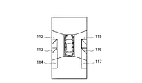
図11は第4実施形態に係る仮駐車目標位置の画像を示す図である。図11に示すように、第4実施形態に係る仮駐車目標位置の画像では、仮駐車目標位置を直線で囲まれた四角形で表現している。 FIG. 11 is a diagram illustrating an image of the temporary parking target position according to the fourth embodiment. As shown in FIG. 11, in the image of the temporary parking target position according to the fourth embodiment, the temporary parking target position is expressed by a rectangle surrounded by a straight line.
例えば、図11では、小さな方形で表現された領域112は左側の並列駐車に対応した仮駐車目標位置を示し、平行四辺形で表現された領域113は左側の斜め駐車に対応した仮駐車目標位置を示し、大きな方形で表現された領域114は左側の縦列駐車に対応した仮駐車目標位置を示している。同様に、小さな方形で表現された領域115は右側の並列駐車に対応した仮駐車目標位置を示し、平行四辺形で表現された領域116は右側の斜め駐車に対応した仮駐車目標位置を示し、大きな方形で表現された領域117は右側の縦列駐車に対応した仮駐車目標位置を示している。
For example, in FIG. 11, a
ここで、並列駐車に対応した領域112、115と斜め駐車に対応した領域113、116は第1及び第2実施形態と同様に、その中心近傍がドアミラーの位置になるように配置されている。
Here, the
[第4実施形態の効果]
以上詳細に説明したように、本発明を適用した第4実施形態に係る駐車支援装置によれば、仮駐車目標位置の画像を直線で囲まれた四角形で表現したので、より鮮明に駐車目標位置を運転者に提示することができる。
[Effect of Fourth Embodiment]
As described above in detail, according to the parking assistance apparatus according to the fourth embodiment to which the present invention is applied, the image of the temporary parking target position is expressed by a rectangle surrounded by a straight line, so that the parking target position is more clearly displayed. Can be presented to the driver.
なお、上述の実施の形態は本発明の一例である。このため、本発明は、上述の実施の形態に限定されることはなく、この実施の形態以外の形態であっても、本発明に係る技術的思想を逸脱しない範囲であれば、設計などに応じて種々の変更が可能であることは勿論である。 The above-described embodiment is an example of the present invention. For this reason, the present invention is not limited to the above-described embodiment, and even if it is a form other than this embodiment, as long as it does not depart from the technical idea according to the present invention, the design and the like Of course, various modifications are possible.
1 駐車支援装置
2 俯瞰映像生成部
3 入力部
4 仮駐車目標位置設定部
5 画像重畳部
6 駐車目標位置指定部
7 駐車誘導制御部
8a〜8d カメラ
9 表示部
10 舵角センサ
11 EPSモータ
DESCRIPTION OF SYMBOLS 1
Claims (11)
予め用意された仮駐車目標位置の画像を、前記俯瞰映像に重畳して表示するための設定を行う仮駐車目標位置設定手段と、
前記仮駐車目標位置の画像を前記俯瞰映像に重畳して表示する画像重畳手段と、
前記俯瞰映像に表示されている実際の駐車目標位置に前記仮駐車目標位置の画像が一致するように前記運転者によって前記自車両が移動された後に、前記実際の駐車目標位置に対応した前記仮駐車目標位置を、前記運転者が駐車目標位置として指定する駐車目標位置指定手段と、
前記駐車目標位置指定手段で指定された前記駐車目標位置へ前記自車両を誘導制御する駐車誘導制御手段とを備え、
前記仮駐車目標位置の画像は、少なくとも並列駐車、縦列駐車を含む複数の駐車形態を示し、
前記仮駐車目標位置設定手段は、前記複数の駐車形態毎にそれぞれ異なる仮駐車目標位置の画像を設定し、
前記画像重畳手段は、前記複数の駐車形態毎にそれぞれ異なる仮駐車目標位置の画像を同時に前記俯瞰映像に重畳して表示することを特徴とする駐車支援装置。 A bird's-eye view video generating means for converting a video around the host vehicle to generate a bird's-eye view surrounding the host vehicle;
A provisional parking target position setting means for performing a setting for displaying an image of a provisional parking target position prepared in advance on the overhead view image;
Image superimposing means for superimposing and displaying the image of the temporary parking target position on the overhead view video;
After the host vehicle has been moved by the driver so that the image of the temporary parking target position matches the actual parking target position displayed in the overhead view video, the temporary parking position corresponding to the actual parking target position is displayed. A parking target position specifying means for specifying a parking target position as the parking target position by the driver;
Parking guidance control means for guiding and controlling the host vehicle to the parking target position designated by the parking target position designation means ,
The image of the temporary parking target position shows a plurality of parking modes including at least parallel parking and parallel parking,
The temporary parking target position setting means sets different images of the temporary parking target position for each of the plurality of parking modes,
The said image superimposing means superimposes and displays the image of the temporary parking target position which is different for every said several parking form on the said bird's-eye view image simultaneously, The parking assistance apparatus characterized by the above-mentioned .
予め用意された仮駐車目標位置の画像を、前記俯瞰映像に重畳して表示するための設定を行う仮駐車目標位置設定ステップと、
前記仮駐車目標位置の画像を前記俯瞰映像に重畳して表示する画像重畳ステップと、
前記俯瞰映像に表示されている実際の駐車目標位置に前記仮駐車目標位置の画像が一致するように前記運転者によって前記自車両が移動された後に、前記実際の駐車目標位置に対応した前記仮駐車目標位置を、前記運転者が駐車目標位置として指定する駐車目標位置指定ステップと、
前記駐車目標位置指定ステップで指定された前記駐車目標位置へ前記自車両を誘導制御する駐車誘導制御ステップとを含み、
前記仮駐車目標位置の画像は、少なくとも並列駐車、縦列駐車を含む複数の駐車形態を示し、
前記仮駐車目標位置設定ステップでは、前記複数の駐車形態毎にそれぞれ異なる仮駐車目標位置の画像を設定し、
前記画像重畳ステップでは、前記複数の駐車形態毎にそれぞれ異なる仮駐車目標位置の画像を同時に前記俯瞰映像に重畳して表示することを特徴とする駐車支援方法。 A bird's-eye view video generating step for converting a video around the host vehicle to generate a bird's-eye view around the host vehicle;
A provisional parking target position setting step for performing a setting for displaying an image of the provisional parking target position prepared in advance on the overhead view image;
An image superimposing step of superimposing and displaying an image of the temporary parking target position on the overhead view video;
After the host vehicle has been moved by the driver so that the image of the temporary parking target position matches the actual parking target position displayed in the overhead view video, the temporary parking position corresponding to the actual parking target position is displayed. A parking target position designation step in which the driver designates a parking target position as a parking target position;
Look including a parking guidance control step of inducing controlling the vehicle to the specified the target parking position by the target parking position designation step,
The image of the temporary parking target position shows a plurality of parking modes including at least parallel parking and parallel parking,
In the temporary parking target position setting step, images of different temporary parking target positions are set for each of the plurality of parking modes,
In the image superimposing step, an image of a temporary parking target position that is different for each of the plurality of parking modes is simultaneously superimposed and displayed on the overhead view video .
Priority Applications (1)
| Application Number | Priority Date | Filing Date | Title |
|---|---|---|---|
| JP2010132042A JP5605000B2 (en) | 2010-06-09 | 2010-06-09 | Parking assistance device and parking assistance method |
Applications Claiming Priority (1)
| Application Number | Priority Date | Filing Date | Title |
|---|---|---|---|
| JP2010132042A JP5605000B2 (en) | 2010-06-09 | 2010-06-09 | Parking assistance device and parking assistance method |
Publications (2)
| Publication Number | Publication Date |
|---|---|
| JP2011255783A JP2011255783A (en) | 2011-12-22 |
| JP5605000B2 true JP5605000B2 (en) | 2014-10-15 |
Family
ID=45472465
Family Applications (1)
| Application Number | Title | Priority Date | Filing Date |
|---|---|---|---|
| JP2010132042A Active JP5605000B2 (en) | 2010-06-09 | 2010-06-09 | Parking assistance device and parking assistance method |
Country Status (1)
| Country | Link |
|---|---|
| JP (1) | JP5605000B2 (en) |
Family Cites Families (9)
| Publication number | Priority date | Publication date | Assignee | Title |
|---|---|---|---|---|
| JP2002240661A (en) * | 2001-02-19 | 2002-08-28 | Nissan Motor Co Ltd | Parking support device |
| JP3943363B2 (en) * | 2001-10-18 | 2007-07-11 | クラリオン株式会社 | Parking assistance device |
| JP2004106615A (en) * | 2002-09-17 | 2004-04-08 | Calsonic Kansei Corp | Parking support system |
| JP4061219B2 (en) * | 2002-11-01 | 2008-03-12 | 矢崎総業株式会社 | Parking assistance device |
| JP4235051B2 (en) * | 2003-08-29 | 2009-03-04 | トヨタ自動車株式会社 | Parking assistance device |
| WO2007058325A1 (en) * | 2005-11-17 | 2007-05-24 | Aisin Seiki Kabushiki Kaisha | Parking assisting device and parking assisting method |
| JP2007290433A (en) * | 2006-04-21 | 2007-11-08 | Denso Corp | Parking support system |
| JP4635017B2 (en) * | 2007-02-22 | 2011-02-16 | アイシン精機株式会社 | Parking assistance device |
| JP5076819B2 (en) * | 2007-11-12 | 2012-11-21 | 日産自動車株式会社 | Vehicle driving support device and vehicle driving support method |
-
2010
- 2010-06-09 JP JP2010132042A patent/JP5605000B2/en active Active
Also Published As
| Publication number | Publication date |
|---|---|
| JP2011255783A (en) | 2011-12-22 |
Similar Documents
| Publication | Publication Date | Title |
|---|---|---|
| JP5003946B2 (en) | Parking assistance device | |
| US20200051299A1 (en) | Driving support apparatus for tow coupling | |
| JP5212748B2 (en) | Parking assistance device | |
| JP4907883B2 (en) | Vehicle periphery image display device and vehicle periphery image display method | |
| JP5982750B2 (en) | Parking assistance device and parking assistance method | |
| JP5872517B2 (en) | Vehicle periphery display device | |
| JP3445197B2 (en) | Driving operation assist device | |
| JP5747181B2 (en) | Parking assistance device | |
| WO2000020257A1 (en) | Driving assisting device and recording medium | |
| JP5087885B2 (en) | Parking assistance device and parking assistance method | |
| JP5852076B2 (en) | Vehicle periphery display device | |
| JP2008055958A (en) | Parking assist method and parking assist device | |
| JP5380994B2 (en) | Parking assistance device and parking assistance method | |
| JP2001347909A (en) | Driving operation assisting method and device | |
| JP2007055378A (en) | Apparatus and method for supporting parking | |
| JP2011155651A (en) | Apparatus and method for displaying vehicle perimeter image | |
| JP5273068B2 (en) | Vehicle periphery monitoring device | |
| JP4967604B2 (en) | Parking assistance system | |
| JP2008213647A (en) | Parking assist method and parking assist system | |
| JP7286276B2 (en) | PARKING ASSIST DEVICE AND CONTROL METHOD FOR PARKING ASSIST DEVICE | |
| JP5605000B2 (en) | Parking assistance device and parking assistance method | |
| JP6014569B2 (en) | Parking assistance device | |
| JP2012166689A (en) | Driving assistance apparatus | |
| KR20160112674A (en) | Parking assist system with the picture and distance correction | |
| KR20120086574A (en) | Parking guidance method of vehicles |
Legal Events
| Date | Code | Title | Description |
|---|---|---|---|
| A621 | Written request for application examination |
Free format text: JAPANESE INTERMEDIATE CODE: A621 Effective date: 20130424 |
|
| A977 | Report on retrieval |
Free format text: JAPANESE INTERMEDIATE CODE: A971007 Effective date: 20131218 |
|
| A131 | Notification of reasons for refusal |
Free format text: JAPANESE INTERMEDIATE CODE: A131 Effective date: 20140204 |
|
| A521 | Written amendment |
Free format text: JAPANESE INTERMEDIATE CODE: A523 Effective date: 20140327 |
|
| TRDD | Decision of grant or rejection written | ||
| A01 | Written decision to grant a patent or to grant a registration (utility model) |
Free format text: JAPANESE INTERMEDIATE CODE: A01 Effective date: 20140729 |
|
| A61 | First payment of annual fees (during grant procedure) |
Free format text: JAPANESE INTERMEDIATE CODE: A61 Effective date: 20140811 |
|
| R151 | Written notification of patent or utility model registration |
Ref document number: 5605000 Country of ref document: JP Free format text: JAPANESE INTERMEDIATE CODE: R151 |