JP4635013B2 - Carton with opening and positioning mechanism - Google Patents
Carton with opening and positioning mechanism Download PDFInfo
- Publication number
- JP4635013B2 JP4635013B2 JP2006553210A JP2006553210A JP4635013B2 JP 4635013 B2 JP4635013 B2 JP 4635013B2 JP 2006553210 A JP2006553210 A JP 2006553210A JP 2006553210 A JP2006553210 A JP 2006553210A JP 4635013 B2 JP4635013 B2 JP 4635013B2
- Authority
- JP
- Japan
- Prior art keywords
- carton
- line
- panel
- positioning assembly
- bottom panel
- Prior art date
- Legal status (The legal status is an assumption and is not a legal conclusion. Google has not performed a legal analysis and makes no representation as to the accuracy of the status listed.)
- Expired - Fee Related
Links
- 230000007246 mechanism Effects 0.000 title description 8
- 238000000034 method Methods 0.000 claims description 10
- 230000008878 coupling Effects 0.000 claims description 6
- 238000010168 coupling process Methods 0.000 claims description 6
- 238000005859 coupling reaction Methods 0.000 claims description 6
- 238000005096 rolling process Methods 0.000 claims description 5
- 239000000853 adhesive Substances 0.000 claims description 4
- 230000001070 adhesive effect Effects 0.000 claims description 4
- 239000000463 material Substances 0.000 claims description 2
- 235000013361 beverage Nutrition 0.000 description 8
- 235000013305 food Nutrition 0.000 description 5
- 239000011087 paperboard Substances 0.000 description 3
- 230000000712 assembly Effects 0.000 description 2
- 238000000429 assembly Methods 0.000 description 2
- 239000000428 dust Substances 0.000 description 2
- 238000004026 adhesive bonding Methods 0.000 description 1
- 235000015895 biscuits Nutrition 0.000 description 1
- 150000001875 compounds Chemical class 0.000 description 1
- 239000003292 glue Substances 0.000 description 1
- 230000005484 gravity Effects 0.000 description 1
- 238000012986 modification Methods 0.000 description 1
- 230000004048 modification Effects 0.000 description 1
- 239000010705 motor oil Substances 0.000 description 1
- 238000004806 packaging method and process Methods 0.000 description 1
Images


Classifications
-
- B—PERFORMING OPERATIONS; TRANSPORTING
- B65—CONVEYING; PACKING; STORING; HANDLING THIN OR FILAMENTARY MATERIAL
- B65D—CONTAINERS FOR STORAGE OR TRANSPORT OF ARTICLES OR MATERIALS, e.g. BAGS, BARRELS, BOTTLES, BOXES, CANS, CARTONS, CRATES, DRUMS, JARS, TANKS, HOPPERS, FORWARDING CONTAINERS; ACCESSORIES, CLOSURES, OR FITTINGS THEREFOR; PACKAGING ELEMENTS; PACKAGES
- B65D71/00—Bundles of articles held together by packaging elements for convenience of storage or transport, e.g. portable segregating carrier for plural receptacles such as beer cans or pop bottles; Bales of material
- B65D71/06—Packaging elements holding or encircling completely or almost completely the bundle of articles, e.g. wrappers
- B65D71/12—Packaging elements holding or encircling completely or almost completely the bundle of articles, e.g. wrappers the packaging elements, e.g. wrappers being formed by folding a single blank
- B65D71/36—Packaging elements holding or encircling completely or almost completely the bundle of articles, e.g. wrappers the packaging elements, e.g. wrappers being formed by folding a single blank having a tubular shape, e.g. tubular wrappers, with end walls
-
- B—PERFORMING OPERATIONS; TRANSPORTING
- B65—CONVEYING; PACKING; STORING; HANDLING THIN OR FILAMENTARY MATERIAL
- B65D—CONTAINERS FOR STORAGE OR TRANSPORT OF ARTICLES OR MATERIALS, e.g. BAGS, BARRELS, BOTTLES, BOXES, CANS, CARTONS, CRATES, DRUMS, JARS, TANKS, HOPPERS, FORWARDING CONTAINERS; ACCESSORIES, CLOSURES, OR FITTINGS THEREFOR; PACKAGING ELEMENTS; PACKAGES
- B65D2571/00—Bundles of articles held together by packaging elements for convenience of storage or transport, e.g. portable segregating carrier for plural receptacles such as beer cans, pop bottles; Bales of material
- B65D2571/00123—Bundling wrappers or trays
- B65D2571/00129—Wrapper locking means
- B65D2571/00135—Wrapper locking means integral with the wrapper
- B65D2571/00141—Wrapper locking means integral with the wrapper glued
-
- B—PERFORMING OPERATIONS; TRANSPORTING
- B65—CONVEYING; PACKING; STORING; HANDLING THIN OR FILAMENTARY MATERIAL
- B65D—CONTAINERS FOR STORAGE OR TRANSPORT OF ARTICLES OR MATERIALS, e.g. BAGS, BARRELS, BOTTLES, BOXES, CANS, CARTONS, CRATES, DRUMS, JARS, TANKS, HOPPERS, FORWARDING CONTAINERS; ACCESSORIES, CLOSURES, OR FITTINGS THEREFOR; PACKAGING ELEMENTS; PACKAGES
- B65D2571/00—Bundles of articles held together by packaging elements for convenience of storage or transport, e.g. portable segregating carrier for plural receptacles such as beer cans, pop bottles; Bales of material
- B65D2571/00123—Bundling wrappers or trays
- B65D2571/00555—Wrapper opening devices
- B65D2571/00561—Lines of weakness
- B65D2571/00574—Lines of weakness whereby contents can still be carried after the line has been torn
- B65D2571/0058—The tear line defining a dispensing aperture provided with means for preventing the articles from freely exiting the wrapper, e.g. by rolling out
-
- B—PERFORMING OPERATIONS; TRANSPORTING
- B65—CONVEYING; PACKING; STORING; HANDLING THIN OR FILAMENTARY MATERIAL
- B65D—CONTAINERS FOR STORAGE OR TRANSPORT OF ARTICLES OR MATERIALS, e.g. BAGS, BARRELS, BOTTLES, BOXES, CANS, CARTONS, CRATES, DRUMS, JARS, TANKS, HOPPERS, FORWARDING CONTAINERS; ACCESSORIES, CLOSURES, OR FITTINGS THEREFOR; PACKAGING ELEMENTS; PACKAGES
- B65D2571/00—Bundles of articles held together by packaging elements for convenience of storage or transport, e.g. portable segregating carrier for plural receptacles such as beer cans, pop bottles; Bales of material
- B65D2571/00123—Bundling wrappers or trays
- B65D2571/00555—Wrapper opening devices
- B65D2571/00561—Lines of weakness
- B65D2571/00598—The tearable part having a specific use
- B65D2571/00604—The tearable part having a specific use for supporting the wrapper in a dispensing position, e.g. inclined
-
- B—PERFORMING OPERATIONS; TRANSPORTING
- B65—CONVEYING; PACKING; STORING; HANDLING THIN OR FILAMENTARY MATERIAL
- B65D—CONTAINERS FOR STORAGE OR TRANSPORT OF ARTICLES OR MATERIALS, e.g. BAGS, BARRELS, BOTTLES, BOXES, CANS, CARTONS, CRATES, DRUMS, JARS, TANKS, HOPPERS, FORWARDING CONTAINERS; ACCESSORIES, CLOSURES, OR FITTINGS THEREFOR; PACKAGING ELEMENTS; PACKAGES
- B65D2571/00—Bundles of articles held together by packaging elements for convenience of storage or transport, e.g. portable segregating carrier for plural receptacles such as beer cans, pop bottles; Bales of material
- B65D2571/00123—Bundling wrappers or trays
- B65D2571/00648—Elements used to form the wrapper
- B65D2571/00654—Blanks
- B65D2571/0066—Blanks formed from one single sheet
-
- B—PERFORMING OPERATIONS; TRANSPORTING
- B65—CONVEYING; PACKING; STORING; HANDLING THIN OR FILAMENTARY MATERIAL
- B65D—CONTAINERS FOR STORAGE OR TRANSPORT OF ARTICLES OR MATERIALS, e.g. BAGS, BARRELS, BOTTLES, BOXES, CANS, CARTONS, CRATES, DRUMS, JARS, TANKS, HOPPERS, FORWARDING CONTAINERS; ACCESSORIES, CLOSURES, OR FITTINGS THEREFOR; PACKAGING ELEMENTS; PACKAGES
- B65D2571/00—Bundles of articles held together by packaging elements for convenience of storage or transport, e.g. portable segregating carrier for plural receptacles such as beer cans, pop bottles; Bales of material
- B65D2571/00123—Bundling wrappers or trays
- B65D2571/00709—Shape of the formed wrapper, i.e. shape of each formed element if the wrapper is made from more than one element
- B65D2571/00722—Shape of the formed wrapper, i.e. shape of each formed element if the wrapper is made from more than one element tubular with end walls, e.g. walls not extending on the whole end surface
- B65D2571/00728—Shape of the formed wrapper, i.e. shape of each formed element if the wrapper is made from more than one element tubular with end walls, e.g. walls not extending on the whole end surface the end walls being closed by gluing
-
- B—PERFORMING OPERATIONS; TRANSPORTING
- B65—CONVEYING; PACKING; STORING; HANDLING THIN OR FILAMENTARY MATERIAL
- B65D—CONTAINERS FOR STORAGE OR TRANSPORT OF ARTICLES OR MATERIALS, e.g. BAGS, BARRELS, BOTTLES, BOXES, CANS, CARTONS, CRATES, DRUMS, JARS, TANKS, HOPPERS, FORWARDING CONTAINERS; ACCESSORIES, CLOSURES, OR FITTINGS THEREFOR; PACKAGING ELEMENTS; PACKAGES
- B65D2571/00—Bundles of articles held together by packaging elements for convenience of storage or transport, e.g. portable segregating carrier for plural receptacles such as beer cans, pop bottles; Bales of material
- B65D2571/00123—Bundling wrappers or trays
- B65D2571/00833—Other details of wrappers
- B65D2571/00882—Supporting members
Landscapes
- Engineering & Computer Science (AREA)
- Mechanical Engineering (AREA)
- Cartons (AREA)
- Packages (AREA)
Description
[発明の分野]
本発明は包括的には、物品を保持し、且つそれらの物品を手が届きやすいように位置決めするためのカートンに関する。詳細には、本発明は、カートン内で物品を位置決めするための傾斜機構を有する小出しカートンに関する。
[Field of the Invention]
The present invention relates generally to cartons for holding articles and positioning them for easy access. In particular, the present invention relates to a dispensing carton having a tilting mechanism for positioning articles within the carton.
[関連出願の相互参照]
本出願は、2004年2月10日に出願された米国特許仮出願第60/543,382号の優先権を主張し、この出願は、その全体が本明細書に述べられているかのように参照によって援用される。
[Cross-reference of related applications]
This application claims the priority of US Provisional Application No. 60 / 543,382, filed February 10, 2004, which application is as if fully set forth herein. Incorporated by reference.
[発明の背景]
物品の陳列又は小出しのための位置決め機構を備えた閉鎖型カートンが、従来、使用されてきた。これらのカートンの多くは、使用者がカートンの一部分を切り離し、その部分を操作して位置決めアセンブリを作り、そのアセンブリをカートンの下に置くことを必要とする。他のタイプのカートンには、位置決めアセンブリを所定位置に保持する、又は位置決めアセンブリをカートンに付着させるために接着剤を必要とする位置決め機構を備えるものもあれば、取り付けられた位置決め機構を有するさらに別のカートンには、使用者が位置決めアセンブリをカートン内の事前形成スロットに挿入することを必要とするものもある。多くの場合、使用者が位置決めアセンブリを係合させた後、カートンの構造保全性が破壊され、また一旦位置決め機構がカートンから取り除かれると、使用者は一般的にカートンを閉鎖し直すことができない。さらに、多くの従来型カートン位置決めアセンブリは、構造的に弱く、且つ過大な重量によって容易に平らになってしまう。
[Background of the invention]
Closed cartons with positioning mechanisms for displaying or dispensing items have been used in the past. Many of these cartons require a user to detach a portion of the carton, manipulate that portion to create a positioning assembly, and place the assembly under the carton. Other types of cartons include a positioning mechanism that holds the positioning assembly in place or requires an adhesive to attach the positioning assembly to the carton, while having an attached positioning mechanism Other cartons require the user to insert the positioning assembly into a pre-formed slot in the carton. In many cases, after the user engages the positioning assembly, the structural integrity of the carton is destroyed, and once the positioning mechanism is removed from the carton, the user generally cannot reclose the carton. . Furthermore, many conventional carton positioning assemblies are structurally weak and easily flatten due to excessive weight.
[発明の概要]
本発明は包括的には、物品を保持し、且つそれらの物品を手が届きやすいように位置決めするための位置決めアセンブリを備えるカートン、及びそのようなカートンを位置決めする方法に関する。本発明は、たとえば、食品及び飲料等の製品を収容している物品の小出しの際に使用されることができる。これらの物品は、缶、ボトル及びペット(PET)容器等の飲料容器とともに、食品又は食品でない商品の包装に使用されるもの等の、好ましくは形状が丸形の他の容器を含むことができる。本発明の1つの態様では、カートンは、接着剤を使用せずに容易に位置決め可能な位置決めアセンブリを備えている。本発明の別の態様では、カートンは、位置決めアセンブリの係合後に閉鎖し直すことができる位置決めアセンブリを備えている。本発明のさらなる態様では、カートンは、使用者がカートンの一部分を切り離す必要がない位置決めアセンブリを備えている。
[Summary of Invention]
The present invention relates generally to cartons with positioning assemblies for holding articles and positioning the articles for easy access, and methods for positioning such cartons. The present invention can be used, for example, when dispensing articles containing products such as food and beverages. These articles can include other containers, preferably round in shape, such as those used for packaging food or non-food products, as well as beverage containers such as cans, bottles and pet (PET) containers. . In one aspect of the invention, the carton includes a positioning assembly that can be easily positioned without the use of an adhesive. In another aspect of the invention, the carton includes a positioning assembly that can be closed again after engagement of the positioning assembly. In a further aspect of the invention, the carton includes a positioning assembly that does not require the user to cut off a portion of the carton.
本発明はまた、特定形状に切断され、それから特定領域に折り目、刻み目、切れ目又はミシン目を付けた、板紙ブランク等のカートンブランクを含む。カートンブランクは、折り目又は折り線の間に細長いパネルを画定し、パネルのそれぞれの端部にダストフラップを含む。カートンブランクを折り曲げてスリーブを形成し、完全に組み立てて、端部フラップを閉じたとき、組み立てられたカートンは、前又は前方端部、後方端部及び上壁、底壁、前後壁、及び第1の側壁及び第2の側壁を有する。 The present invention also includes a carton blank, such as a paperboard blank, cut to a specific shape and then creased, scored, cut or perforated in a specific area. The carton blank defines an elongated panel between creases or fold lines and includes a dust flap at each end of the panel. When the carton blank is folded to form a sleeve, fully assembled, and the end flaps are closed, the assembled carton will have a front or front end, a rear end and top wall, a bottom wall, a front and back wall, and a second Having one side wall and a second side wall.
説明のために、本発明は、ペットボトル又は飲料缶に入れた飲料を収容するような寸法及び大きさの板紙カートンとして開示される。図面に示されたカートンは、12個の物品を2×6配列にして保持する寸法であるが、本発明は、いずれの特定の寸法又は大きさにも制限されない。たとえば、本発明は、3×4、2×4、2×5等の他の配列で物品を保持する寸法及び形状でもうまく働くであろう。カートンは、物品に手が届きやすくする開口機構や、物品を前端部に位置決めする位置決めアセンブリを含めたさまざまな独特の機構を備える。 For purposes of illustration, the present invention is disclosed as a paperboard carton that is sized and sized to contain a beverage in a plastic bottle or beverage can. The carton shown in the drawings is dimensioned to hold twelve articles in a 2 × 6 array, but the invention is not limited to any particular dimension or size. For example, the present invention will work well with dimensions and shapes that hold articles in other arrangements such as 3 × 4, 2 × 4, 2 × 5, and the like. The carton includes a variety of unique mechanisms, including an opening mechanism that provides easy access to the article and a positioning assembly that positions the article at the front end.
[発明の詳細な説明]
本発明をより完全に理解するために、以下の詳細な説明及び添付図面を参照する必要があり、図面全体を通して同一の参照番号が対応部分を示している。
Detailed Description of the Invention
For a more complete understanding of the present invention, reference should be made to the following detailed description and accompanying drawings, wherein like reference numerals designate corresponding parts throughout.
本発明のカートンの理解及び説明を容易にするために、本明細書に記載する構成要素及び符号は、カートン及びブランクの半割部分を区別するために、「上方」、「下方」、「上部」、「底部」、「前部」及び「後部」という用語を使用する。しかしながら、これらの規定は、単に本記載の説明及び理解を容易にするために含まれているだけであって、決して限定的ではない。たとえば、「上方」、「下方」等のパネルの説明は、「第1」、「第2」等と呼ぶこともできる。 In order to facilitate understanding and description of the carton of the present invention, the components and symbols described herein are "upper", "lower", "upper" to distinguish between carton and blank halves. "," Bottom "," front "and" rear "are used. However, these provisions are included merely to facilitate explanation and understanding of the description and are in no way limiting. For example, descriptions of panels such as “upper” and “lower” can also be referred to as “first”, “second”, and the like.
切り取り線は、連続的であることができ、ミシン目、切れ目、刻み目、折り目、折り線、切り込み線、切り取り線の任意の組み合わせ、又は容器ブランク内に形成された上記及び他の包含物の任意の組み合わせから成ることができる。 The tear line can be continuous and perforated, scored, scored, creased, fold line, scored line, any combination of tear lines, or any of the above and other inclusions formed in a container blank Can consist of a combination of
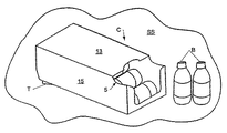
図1は、本発明の一実施形態に従ったカートンCの斜視図であって、開口フラップが取り除かれている。本発明の図示の実施形態の位置決めアセンブリは、傾斜アセンブリTを有し、これがその動作可能位置に示されている。2つの管形の飲料ペットボトルが、図1のカートンの開口端部すなわち前端部5のそばで支持面SS上に配置されている。傾斜アセンブリTは、カートンCの後方端部6に位置決めされている。
FIG. 1 is a perspective view of a carton C according to one embodiment of the present invention with the opening flap removed. The positioning assembly of the illustrated embodiment of the present invention has a tilt assembly T, which is shown in its operable position. Two tubular beverage plastic bottles are arranged on the support surface SS by the open or
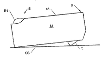
図2は、図1のカートンの側面図である。図2において、ペットボトルBがカートン内に2×6配列にして収容されており、上段の各ボトルは、下段の対応のボトルの真上に位置決めされている。ペットボトルの上段の第1のボトルB1が、開口端部すなわち前端部5に見える。
FIG. 2 is a side view of the carton of FIG. In FIG. 2, PET bottles B are accommodated in a 2 × 6 array in a carton, and each upper bottle is positioned directly above a corresponding bottle in the lower stage. The first bottle B1 in the upper stage of the plastic bottle is visible at the open end, that is, the
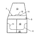
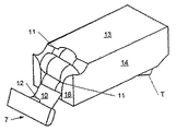
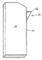
図3は、カートンCの端面図であって、ディスペンサ7がカートンCの残り部分に完全に接続されており、それにより、6本のペットボトルの2段が完全閉鎖型カートン内に収容されている。図3に示されているディスペンサ7は、境界線11によって画定された開口フラップ10を有する。この境界線は、使用者がディスペンサ7を線11に沿ってカートンから手動で分離させて、ディスペンサ7をカートンCの残り部分から取り除くことができるようにする切れ目、切り込み線、又は他の弱め領域であることができる。任意選択で、開口フラップ10はカートン壁の1つに沿ってフィンガフラップ12を画定してもよい。フィンガフラップ12は、使用者がフィンガフラップ12を内側へ押し込み、線11に沿ってカートンを破断することにより、カートンを開口する初期動作を助けるために設けることができる。好ましくは、フィンガフラップ12は、カートンの上壁13の位置にあるが、本発明は、側壁14及び15の一方又は両方、或いは前壁16等の他の壁に1つ又は複数のフィンガフラップを配置するように構成することもできるであろう。
FIG. 3 is an end view of the carton C, with the
図4は、ペットボトルを保持している完全閉鎖型カートンCを示し、ディスペンサ7の除去を説明する。使用者は、1本又は複数本の指を内側へ押し込み、それにより、カートンCを、最初に線11の部分、即ちフィンガフラップ12を画定する部分に沿って開く。使用者は次に、フラップ12及びフラップ10を外向きに引っ張ってカートンの残り部分から離し、それにより、開口フラップ10を境界線11に沿ってカートンCの残り部分から分離させ始める。フィンガフラップ12が組み込まれていない場合でも、開口処理は通常、線11の、カートンの上壁13内に画定されている部分に沿って始まる。開口フラップ10を引っ張り続けると、フラップ10は、第1の側壁14及び第2の側壁15内に画定された線11に沿っても分離する。フラップ10を引っ張り続けることにより、図5に示されているように、フラップ10が前壁16から分離し始める。この時点で、ディスペンサ7は一体構造体として、図5に示されているようにカートンに取り付けられたままであって、バスケットを形成することができるか、又は任意選択で、開口端部すなわち前端部5に沿ってほぼ点17Aから点17Bまで延びる境界線部分17に沿って引き裂くことにより、カートンから完全に取り除くことができる。部分17は一般的に、カートンの底部パネルから上方に、カートン内に保持される容器の1つの直径より短い距離の間隔が置かれており、この距離は、ディスペンサが開いている間に容器がカートンから転がり出ることを防止し、且つカートンの構造保全性を維持するのに十分である。
FIG. 4 shows a fully closed carton C holding a plastic bottle and illustrates the removal of the
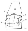
図6は、開口フラップ10をカートンから取り除いた状態にある、2×6配列にしてペットボトルBを保持しているカートンCを示す。境界線11によって大まかに示されているように、上壁13、側壁14及び15、及び前壁16の縁部によってアクセス開口8が画定されている。カートン内に保持されている容器又はボトルは、自動的に小出しされないが、アクセス開口8でカートン内の最前方の容器を掴むことによって個別に容易に取り出すことができるように、カートンの前端部に位置決めされている。
FIG. 6 shows the carton C holding the plastic bottle B in a 2 × 6 array with the
好ましくは、カートン内の物品は、缶又はボトル等の、丸い側壁を有する管状であり、そのため、後述するように傾斜アセンブリを係合させたとき、物品が前方に転がる。本発明のカートンは、飲料缶、ペットボトル、及びロールやビスケット等の食品容器を保持するのに理想的に適する。モータオイル等の食品でない商品を保持する他の構造の任意の他の容器を本カートン内に保持して、自動的に位置決めすることができる。 Preferably, the article in the carton is a tube with rounded side walls, such as a can or bottle, so that the article rolls forward when the tilt assembly is engaged as described below. The carton of the present invention is ideally suited for holding beverage cans, plastic bottles, and food containers such as rolls and biscuits. Any other container of other structure holding non-food items such as motor oil can be held in the carton and automatically positioned.
カートンはまた、カートンの後方端部9を上昇させるために、係合させる、すなわち動作可能位置に置くことができる傾斜アセンブリTを有することもできる。傾斜アセンブリTを係合させたとき、カートンの後方端部9が、カウンタ、冷蔵庫の棚、又はカートンを支持するキャビネット又は棚等の支持面SSから上方に持ち上げられる。カートンをこの上昇位置に手動で設置すると、管状容器が重力によって後方端部9から開口端部すなわち前端部5の方へ前方に回転し、それにより、容器は、使用者がアクセス開口8からカートン内に手を伸ばしてそれらを容易に取り出すことができるように位置決めされる。
The carton can also have a tilting assembly T that can be engaged, ie placed in an operable position, to raise the
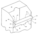
図7は、カートンの後方下側から見たカートンCの後方端部9の端面図である。底壁21は、好ましくは切り込み線である刻み目線22に沿って終端している。カートンの後壁23は、切れ目線22から上方に、後壁23が上壁13と合流する上縁部24まで延びている。カートンCの傾斜アセンブリTは、ミシン目、切れ目がない折り目、切れ目入り折り目及び切り込み線を含めたさまざまな事前形成された線によって画定される。しかしながら、本発明の傾斜アセンブリTは上記のような線を使用してうまく働くが、本明細書に記載する特定の組み合わせの代わりに、これらの線の他の組み合わせを使用できることは、当業者には理解されるであろう。
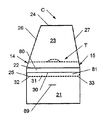
FIG. 7 is an end view of the
図7に示されているように、ミシン目25は、点32から底壁、即ち、パネル21を横切って側壁14まで延びている。図8は、側壁14の下方後隅部を横切って、側壁14が後壁23と合流するカートン縁部26の方に上向きに続く線25を示す。線25は次に、後壁23を横切って、後壁23が側壁15と合流する反対側のカートン縁部27まで延びている。線25と底壁21との間の距離は、カートン内に保持される容器の1つの直径より短いが、他の高さにすることもできる。任意選択で、図8に示されているように、タブ又はフィンガフラップ28をミシン目25によって後壁23内に画定することができる。線25は同様に、側壁15の下方後隅部を横切って底壁21まで、さらに図7に示された点33まで延びている。
As shown in FIG. 7,
再び図7を参照すると、刻み目線22が、後壁23と底壁21とを結合するカートン縁部に沿って形成されている。図7に示されているように、刻み目線22から底壁21に沿って前方に間隔をおいて切れ目入り折り線30が設けられている。線22及び30の間に矩形パネル80が画定される。やはり図7には、切れ目がない折り線31が示されており、これは、線30から前方に間隔をおいて底壁21に沿って点32から33まで延びている。折り線30は、線22及び31間から等距離に位置する。傾斜した端部分(図7)を有するパネル81が、線30及び31間に画定されている。パネル81の傾斜端部分は、ミシン目25の、点32から側壁14まで、及び点33から側壁15まで延びる部分によって画定される。パネル80及び81を有する傾斜フラップ35が、線25及び31間に画定される。
Referring again to FIG. 7, score lines 22 are formed along the carton edge connecting the
傾斜アセンブリTを位置決めするために、タブ又はフィンガフラップ28に沿って内側に押し、それから外向きに引っ張ってカートンCから離し、それにより、後壁23をミシン目25に沿って引き裂き始めることにより、傾斜フラップ35を引き下ろす。この時点で、使用者はカートンの後端部を持ち上げ、それにより、それをカウンタ又は棚等の支持面SSから、フラップ35を底壁21の下方へ移動させることができるまで十分に高く上昇させる。これにより、図10に示されているように、傾斜フラップ35を、側壁14及び15の下方後隅部を横切り、底壁21のミシン目25に沿って点32及び33まで引き裂くことができる。この時、傾斜アセンブリTは、線31に沿ってカートンにヒンジ式に取り付けられ、且つカートンの構造保全性を保持する一体構造体を構成する。
(i)上部パネル、2つの側部パネル、底部パネル、第1の閉鎖端部、及び出口端部である第2の閉鎖端部と、(ii)該第2の閉鎖端部に位置する開口と、(iii)該第1の閉鎖端部に位置する位置決めアセンブリであって、前記底部パネル上の第1の点から該底部パネル上の第2の点まで延びる折り線、及び該第1の点から該底部パネル、該2つの側部パネルの一方、該第1の閉鎖端部、他方の側部パネル及び該底部パネルを横切って該第2の点まで延びる切り取り線によって画定される一体構造体である位置決めアセンブリと、を備える複数の容器を収容している閉鎖型カートンは、
a.該位置決めアセンブリを該切り取り線に沿って引き裂き、
b.該位置決めアセンブリを該折り線を中心にしてヒンジ式に移動させ、それにより、該位置決めアセンブリを該底部パネルと接触させる、
ことにより位置決めされ、該位置決めアセンブリは、該カートンの該第1の閉鎖端部に取り付けられたまま残る。
(i)上部パネル、2つの側部パネル、底部パネル、第1の閉鎖端部、及び出口端部である第2の閉鎖端部と、(ii)該第2の閉鎖端部に位置する開口と、(iii)該第1の閉鎖端部に位置する位置決めアセンブリであって、(a)該底部パネル上の第1の点から該底部パネル上の第2の点まで延びる第1の折り線、(b)該第1の点から該底部パネル、該2つの側部パネルの一方、該第1の閉鎖端部、他方の側部パネル及び該底部パネルを横切って該第2の点まで延びる切り取り線、及び(c)該切り取り線の、該底部パネルを横切って延びる部分上に位置する第3の点及び第4の点の間に延びる第2の折り線によって画定される一体構造体である位置決めアセンブリと、を備える複数の容器を収容している閉鎖型カートンは、
a.該位置決めアセンブリを該切り取り線に沿って引き裂き、
b.該位置決めアセンブリを該第1の折り線を中心にしてヒンジ式に移動させ、
c.該位置決めアセンブリを該第2の折り線を中心にしてヒンジ式に移動させ、それにより、該位置決めアセンブリを該底部パネルと接触させる、
ことにより位置決めされ、該位置決めアセンブリは、該カートンの該第1の閉鎖端部に取り付けられたまま残る。
To position the tilt assembly T, push inward along the tab or
(I) a top panel, two side panels, a bottom panel, a first closed end, and a second closed end that is an exit end; and (ii) an opening located at the second closed end. And (iii) a positioning assembly located at the first closed end, the fold line extending from a first point on the bottom panel to a second point on the bottom panel, and the first A unitary structure defined by a bottom line, one of the two side panels, the first closed end, the other side panel and a tear line extending across the bottom panel from the point to the second point A closed carton containing a plurality of containers comprising a body positioning assembly;
a. Tearing the positioning assembly along the tear line;
b. Moving the positioning assembly hinged about the fold line, thereby contacting the positioning assembly with the bottom panel;
The positioning assembly remains attached to the first closed end of the carton.
(I) a top panel, two side panels, a bottom panel, a first closed end, and a second closed end that is an exit end; and (ii) an opening located at the second closed end. And (iii) a positioning assembly located at the first closed end, wherein (a) a first fold line extending from a first point on the bottom panel to a second point on the bottom panel (B) extending from the first point to the second point across the bottom panel, one of the two side panels, the first closed end, the other side panel, and the bottom panel. A unitary structure defined by a tear line, and (c) a second fold line extending between a third point and a fourth point located on a portion of the tear line that extends across the bottom panel. A closed carton containing a plurality of containers comprising a positioning assembly;
a. Tearing the positioning assembly along the tear line;
b. Moving the positioning assembly hinged about the first fold line;
c. Moving the positioning assembly hinged about the second fold line, thereby contacting the positioning assembly with the bottom panel;
The positioning assembly remains attached to the first closed end of the carton.
図面に示されたような傾斜アセンブリTは、側部パネル内にミシン目又は切り取り線を有する。しかしながら、傾斜アセンブリTは、側部パネルのいずれか一方又は両方の部分を含む必要はないが、本明細書では説明の一貫性及び容易さの点から、それらが図面に示されている。 The tilt assembly T as shown in the drawings has perforations or tear lines in the side panels. However, the tilt assembly T need not include either or both portions of the side panels, but they are shown in the drawings herein for consistency and ease of description.
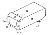
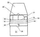
図9Aは、カートンCの側面図であって、線25が点32及び33まで完全に引き裂かれるように、フラップ35が引き出されているところを示す。図9Bは、フラップ35を係合させる、すなわち動作可能位置に適切に位置決めする際の次のステップを示す。図9Bでは、フラップ35の、線25によって画定されるような端部壁23から成る部分が底壁21と接触するように位置決めされている。このフラップ35の位置では、パネル80がパネル81から離れているが、それに近接している。図9Cは、傾斜アセンブリTを位置決めする際の最終ステップを示し、パネル81がパネル80の方に、それらパネル80及び81が互いに接触するまで、押されている。図9Dに示されているように、このフラップ35の位置は、点83から点84まで延びる(線30に対応する)縁部82を生じる。傾斜縁部85が、点83から点86まで延び、傾斜縁部87が点84から点88まで延びている。タブ28を底部パネル21のスリット89に挿入してもよい。その後、カートンCを支持面SS上に載せたとき、傾斜アセンブリTの縁部82、85及び87が集合的にカートンCの支持を行う。傾斜アセンブリTをこの動作可能位置に置いたとき、次にカートンCを支持面SS上に静かに戻して置くことができ、それにより、フラップ35は、図11に示されているように、カートンの下方に完全に折り曲げられる。このように、傾斜フラップ35がカートンCのための後支持面になり、それにより、カートンCの後端部が支持面SSより上方に持ち上げられる。したがって、丸形又は管状側壁を有する容器は後壁23から離れて前壁16の方に転がりやすくなり、上述したように位置決めして容易に取り出すことができる。(図面をわかりやすくするために、図9Dには容器が示されていない。)
FIG. 9A is a side view of carton
所望時にはいつも、図9A〜図9Cに示されたステップの順序を逆にして、それを元の位置に戻すことにより、傾斜アセンブリTを閉鎖し直すことができる。 Whenever desired, the tilt assembly T can be reclosed by reversing the order of steps shown in FIGS. 9A-9C and returning it to its original position.
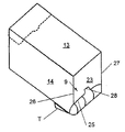
本発明は、上記カートンCを形成するためのカートンブランク90も有する。図12に示されているカートンブランク90は、当該技術分野では既知のSUS板紙等のキャリヤボード(carrier board)から成るが、カートンブランクはいずれの特定の組成物にも制限されない。たとえば、ブランクは、厚紙で、又はプラスチック等の合成シート材料から構成されることもできる。カートンブランク90は、折り目又は折り線50及び折り線51を有し、その間に上部パネル又は壁13が画定されている。前上端部フラップ52が、上部パネル13の一端部に画定され、後上端部フラップ53が、パネル13の他端部に画定されている。上記フラップは、当該技術分野ではダストフラップとしても知られる。折り線54が折り線50から間隔をおいて配置され、その間に側部パネル14を画定している。側部パネル14の前又は前方端部では、前側端部フラップ55が第1の横方向折り線100を介して側部パネル14に接続され、側部パネル14の反対端部すなわち後端部では、後側端部フラップ56が第2の横方向折り線101を介して側部パネル14に接続されている。カートンブランクは第1の自由縁部60を有し、これは、図12に示されているように、折り線54から間隔をおいてそれにほぼ平行であり、それにより、結合フラップ61を画定している。折り線51から間隔をおいてそれに平行に折り線62が配置され、それにより、折り線51及び62間に側部パネル15を画定している。側部フラップ15の前方端部では、前側端部フラップ63が第1の横方向折り線100を介して側部パネル15に接続され、側部パネル15の後方端部では、後側端部フラップ64が第2の横方向折り線101を介して側部パネル15に接続されている。カートンブランク90は、第2の自由縁部65も有し、これは、図12に示されているように、折り線62から間隔をおいてそれにほぼ平行である。底部パネル68が、折り線62と自由縁部65との間に画定されている。前底端部フラップ69が、底部パネル68の前部分に沿って画定され、後底端部フラップ70が、底部パネル68の後部分に画定されている。ブランクには、刻み目/切れ目線11、ミシン目25及び折り線31が設けられ、後述するようにカートンが完全に閉鎖されたとき、これらの線が上述のディスペンサ7及び傾斜アセンブリTを画定するように位置決めされ、且つ構成されている。
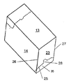
The present invention also includes a carton blank 90 for forming the carton C. The carton blank 90 shown in FIG. 12 consists of a carrier board, such as SUS paperboard, known in the art, but the carton blank is not limited to any particular composition. For example, the blank can be constructed of cardboard or a synthetic sheet material such as plastic. The carton blank 90 has a fold or fold
当業者には既知のように、カートンブランクは、折り目又は折り線に沿って折り曲げられ、それにより、結合フラップ61を底部フラップ68に重ねて付着させてカートンスリーブを形成することができる。図12に示されているカートンブランク90は、このように折り曲げられ、それにより、本発明のカートンCを形成する。膠接着剤又は化合物等の固着手段がフラップ61に塗布され、それにより、カートンを折り曲げた後、フラップ61をフラップ68に固着して、スリーブを形成することができる。やはり当業者には既知のように、カートンCをスリーブの形にしてから、図面に示されているペットボトル又は飲料缶等の容器をスリーブ内に適当な向きで入れる。図示のように、カートンを完全に閉鎖して、適切にひっくり返して上部パネル13を上向きにしたとき、容器はそれぞれ横向きになる。
As known to those skilled in the art, the carton blank can be folded along a crease or fold line so that the connecting
カートンは、上記の端部フラップを折り曲げ、それにより、端部分を閉じ、またカートンを完全に閉鎖するために、たとえば対応の端部フラップを互いに接着することによって、完全に閉鎖される。前端部フラップが協動して前壁16を形成し、後端部フラップが協動して後壁23を形成する。
The carton is completely closed, for example by gluing the corresponding end flaps together, in order to fold the end flaps described above, thereby closing the end portions and also completely closing the carton. The front end flaps cooperate to form the
図13〜図15は、ペットボトルの代わりに飲料缶を封入する、上記のような本発明のカートンを示す。図13は、缶を収容しているカートンの端面図である。図13は、リテーナ壁Wを示し、これらは、ディスペンサ7が開いているとき、上段及び下段の両方の物品が自然にカートンから転がり出ることを防止する。図14は、ディスペンサを取り除いた状態にある、缶を2×6配列に収容している図13のカートンの端面図である。図15は、ディスペンサを取り除き、傾斜アセンブリをその動作可能位置に示す、缶を2×6配列に収容している図13のカートンの側面図である。
FIGS. 13-15 show a carton of the present invention as described above that encloses a beverage can instead of a plastic bottle. FIG. 13 is an end view of a carton containing a can. FIG. 13 shows the retainer wall W, which prevents both the upper and lower articles from naturally rolling out of the carton when the
以上の明細書は、本発明を実施する、発明者が知る最良の態様を示している。本発明の精神及び範囲から逸脱しない限り、本発明に多くの修正を加えることができるので、本発明の幅及び深さは、添付の特許請求の範囲に帰する。 The foregoing specification indicates the best mode known to the inventors for carrying out the invention. Since many modifications can be made to the invention without departing from the spirit and scope of the invention, the breadth and depth of the invention will be attributed to the appended claims.
Claims (40)
上部パネル、2つの側部パネル、底部パネル、第1の閉鎖端部及び第2の閉鎖端部と、
該第1の閉鎖端部に設けられて、該第1の閉鎖端部を該第2の閉鎖端部よりわずかに上方に持ち上げ、それにより、該容器が該第2の閉鎖端部の方に移動するように構成される、位置決めアセンブリと、
を備え、
該位置決めアセンブリは、該カートンに取り付けられたまま残る一体構造体であり、該底部パネルの一部分及び該第1の閉鎖端部の一部分を有すると共に、該底部パネル上の第1の点から該底部パネル上の第2の点まで延びる第1の折り線と、該第1の点から、該底部パネル、該2つの側部パネルの一方の側部パネル、該第1の閉鎖端部、該2つの側部パネルの他方の側部パネル、該底部パネルを横切って該第2の点まで延びる第2の切り取り線とによって画定され、
第1の切り取り線によって、少なくとも該上部パネルと該第2の閉鎖端部に画定される開口をさらに備える、
閉鎖型カートン。A closed carton for carrying a plurality of containers, the closed carton
A top panel, two side panels, a bottom panel, a first closed end and a second closed end;
Provided at the first closed end, lifting the first closed end slightly above the second closed end, so that the container is directed toward the second closed end; A positioning assembly configured to move;
With
The positioning assembly is a monolithic structure that remains attached to the carton, having a portion of the bottom panel and a portion of the first closed end, and from the first point on the bottom panel to the bottom A first fold line extending to a second point on the panel; and from the first point, the bottom panel, one side panel of the two side panels, the first closed end, the 2 Defined by the other side panel of one side panel, a second cut line extending across the bottom panel to the second point;
Further comprising an opening defined by at least the top panel and the second closed end by a first tear line;
Closed carton.
上部パネル(13)、側部パネル(14、15)、底部パネル(68)及び結合フラップ(61)を画定する折り線(50、51、54、62)を内部に有する折り曲げ可能な材料からなるシートと、
該折り線(50、51、54、62)の一端部において、該折り線(50、51、54、62)に対して横断する方向の第1の横方向折り線(100)であって、該第1の横方向折り線(100)は、(a)側端部フラップ(55)を前記側部パネル(14)に、また(b)側端部フラップ(63)を前記側部パネル(15)に接続する、第1の横方向折り線(100)と、
該折り線(50、51、54、62)の他端部において、該折り線(50、51、54、62)に対して横断する方向の第2の横方向折り線(101)であって、該第2の横方向折り線(101)は、(a)側端部フラップ(56)を前記側部パネル(14)に、また(b)側端部フラップ(64)を前記側部パネル(15)に接続する、第2の横方向折り線(101)と、
該上部パネル(13)及び該側端部フラップ(55、63)内に開口を画定する切り取り線(11)と、
該底部パネル(68)上の第1の点(33)から該底部パネル(68)上の第2の点(32)まで延びる折り線(31)であって、該折り線(31)は、該折り線(50、51、54、62)に対して垂直であるが、該折り線のいずれとも交差しない、折り線(31)と、
該第1の点(33)から該底部パネル(68)及び該側部パネル(15)を横切って該第2の横方向折り線(101)まで延び、さらに該側端部フラップ(64)を横切る切り取り線(25)と、
該第2の点(32)から前記底部パネル(68)を横切って延びる切り取り線と、
該結合フラップ(61)及び該側部パネル(14)を横切って該第2の横方向折り線(101)まで延び、さらに該側端部フラップ(56)を横切る切り取り線(25)と、
を有するブランク。A blank (90) forming a closed carton for carrying a plurality of containers, the blank comprising:
Top panel (13), side panel (14, 15), bottom panel (68) and coupling flap (61) defining a folding line (50,51,54,62) from a material that can bend having therein And a sheet
At one end of the in fold lines (50,51,54,62), a first transverse fold line in a direction transverse to該折Ri lines (50,51,54,62) (100) , the first transverse fold line (100), (a) side end flaps on the side panel (55) (14), also (b) side end flaps (63) said side panel to A first lateral fold line (100) connected to (15) ;
At the other end of the in fold lines (50,51,54,62), a second transverse fold line in a direction transverse to the in fold lines (50,51,54,62) at (101) there are, second transverse fold line (101), (a) end flaps (56) on the side panel (14) and said side (b) side end flaps (64) A second lateral fold line (101) connected to the panel (15) ;
Said upper panel (13) and said side end flaps (55, 63) Switching Operation up line defining an opening in the (11),
A bottom panel (68) on the first point (33) from said bottom panel (68) on the second point (32) Ori Ri lines extending to (31), said in fold lines (31) is the perpendicular to the in fold lines (50,51,54,62), does not intersect with any of the in fold line, in fold line (31),
Extending from the first point (33) to said bottom panel (68) and said side panel (15) across the second transverse fold line (101), further the side end flaps (64) switching Operation up line across (25),
A Switching Operation up lines extending across said bottom panel (68) from the point of the second (32),
The coupling flap (61) and said side panel (14) across the second transverse fold line (101) to extend further the side end flaps (56) Switching Operation up line across the (25) ,
With blank.
該底部パネル(68)は、該折り線(62)と向き合う自由縁部を有し、該結合フラップ(61)は、該折り線(54)と向き合う自由縁部を有する、
請求項25に記載のブランク。The side panel (14), said defined by in fold lines (54,50), said top panel (13) is defined by the in fold lines (50, 51), said side panel (15) It is defined by the in fold lines (51, 62), said bottom panel (68) via the in fold lines (62) connected to said side panel (15), the coupling flaps (61) is connected to the side panel (14) via the in fold lines (54),
Said bottom panel (68) has a free edge facing the said in fold lines (62), said coupling flap (61) has a free edge facing the said in fold lines (54),
The blank according to claim 25.
第3の点と第4の点との間に延びる折り線(30)であって、該第3の点は、前記切り取り線(25)と前記折り線(62)との交点によって画定され、該第4の点は、前記底部パネル(68)の前記自由縁部上に位置する、折り線(30)と、
該折り線(30)は、前記折り線(31)と該第2の横方向折り線(101)との間に位置する、
請求項25に記載のブランク。The blank is
A third point and Ori Ri line extending between a fourth point (30), a point of said third intersection point between the Switching Operation up line (25) and said in fold lines (62) defined by, the points fourth, positioned on the free edge of the bottom panel (68), in fold line (30),
The in fold lines (30) is located between the in fold line (31) the second transverse fold line (101),
The blank according to claim 25.
前記底部パネル(68)及び前記結合フラップ(61)を接合させ、それにより、スリーブを形成する、接合させるステップと、
前記容器を該スリーブ内に装入するステップと、
該スリーブの両端部を閉じるステップと、
を含む方法。A method of forming a blank according to claim 25 in a carton,
Joining the bottom panel (68) and the coupling flap (61) , thereby forming a sleeve;
Charging the container into the sleeve;
Closing both ends of the sleeve;
Including methods.
該位置決めアセンブリを該切り取り線に沿って引き裂くステップと、
該位置決めアセンブリを該折り線を中心にしてヒンジ式に移動させ、それにより、該位置決めアセンブリを該底部パネルと接触させる、ヒンジ式に移動させるステップと、
を含み、該位置決めアセンブリは、該カートンの該第1の閉鎖端部に取り付けられたまま残る、位置決め方法。A method for positioning a closed carton containing a plurality of containers, wherein the carton is (i) a top panel, two side panels, a bottom panel, a first closed end, and an outlet end. A second closed end, (ii) an opening located at the second closed end, and (iii) a positioning assembly located at the first closed end, the first assembly on the bottom panel A fold line extending from the first point to a second point on the bottom panel, and from the first point to the bottom panel, one of the two side panels, the first closed end, the other side panel And a positioning assembly that is a unitary structure defined by a tear line extending across the bottom panel to the second point, the method comprising:
Tearing the positioning assembly along the tear line;
Moving the positioning assembly hinged about the fold line, thereby bringing the positioning assembly into contact with the bottom panel;
And the positioning assembly remains attached to the first closed end of the carton.
該位置決めアセンブリを該切り取り線に沿って引き裂くステップと、
該位置決めアセンブリを該第1の折り線を中心にしてヒンジ式に移動させるステップと、
該位置決めアセンブリを該第2の折り線を中心にしてヒンジ式に移動させ、それにより、該位置決めアセンブリを該底部パネルと接触させる、ヒンジ式に移動させるステップと、
を含み、該位置決めアセンブリは、該カートンの該第1の閉鎖端部に取り付けられたまま残る、位置決め方法。A method for positioning a closed carton containing a plurality of containers, wherein the carton is (i) a top panel, two side panels, a bottom panel, a first closed end, and an outlet end. A second closed end; (ii) an opening located at the second closed end; and (iii) a positioning assembly located at the first closed end, comprising: (a) on the bottom panel A first fold line extending from a first point to a second point on the bottom panel; (b) one of the bottom panel and one of the two side panels from the first point; the first closure A tear line extending across the end, the other side panel, and the bottom panel to the second point; and (c) a third point located on a portion of the tear line extending across the bottom panel. And a unitary structure defined by a second fold line extending between the fourth points. Decided and a assembly, the method comprising,
Tearing the positioning assembly along the tear line;
Moving the positioning assembly hinged about the first fold line;
Moving the positioning assembly hinged about the second fold line, thereby bringing the positioning assembly into contact with the bottom panel;
And the positioning assembly remains attached to the first closed end of the carton.
Applications Claiming Priority (2)
| Application Number | Priority Date | Filing Date | Title |
|---|---|---|---|
| US54338204P | 2004-02-10 | 2004-02-10 | |
| PCT/US2005/004149 WO2005077781A1 (en) | 2004-02-10 | 2005-02-09 | Carton having opening and positioning features |
Publications (2)
| Publication Number | Publication Date |
|---|---|
| JP2007522050A JP2007522050A (en) | 2007-08-09 |
| JP4635013B2 true JP4635013B2 (en) | 2011-02-16 |
Family
ID=34860413
Family Applications (1)
| Application Number | Title | Priority Date | Filing Date |
|---|---|---|---|
| JP2006553210A Expired - Fee Related JP4635013B2 (en) | 2004-02-10 | 2005-02-09 | Carton with opening and positioning mechanism |
Country Status (6)
| Country | Link |
|---|---|
| US (1) | US7621438B2 (en) |
| EP (1) | EP1737747A1 (en) |
| JP (1) | JP4635013B2 (en) |
| AU (1) | AU2005212419B2 (en) |
| CA (1) | CA2554483C (en) |
| WO (1) | WO2005077781A1 (en) |
Families Citing this family (39)
| Publication number | Priority date | Publication date | Assignee | Title |
|---|---|---|---|---|
| US6918487B2 (en) | 2003-02-12 | 2005-07-19 | Graphic Packaging International, Inc. | Dispensing system for double stack carton |
| WO2005023761A2 (en) * | 2003-09-11 | 2005-03-17 | Kemia, Inc. | Cytokine inhibitors |
| US7614497B2 (en) | 2003-10-15 | 2009-11-10 | Graphic Packaging International, Inc. | Display/vending carton |
| US7401711B2 (en) * | 2004-02-10 | 2008-07-22 | Graphic Packaging International, Inc. | Carton having improved opening features |
| BRPI0516485A (en) * | 2004-10-29 | 2008-09-09 | Graphic Packaging Int Inc | matrix for forming a package; headquarters; combination; packaging for containing a plurality of containers and method of removing articles from a package |
| DE602005022479D1 (en) | 2004-10-29 | 2010-09-02 | Graphic Packaging Int Inc | CARTON WITH OPENING DEVICE |
| CA2586426A1 (en) * | 2004-11-12 | 2006-05-18 | Graphic Packaging International, Inc. | Cartons having tilt features |
| US7614543B1 (en) * | 2005-01-07 | 2009-11-10 | The C. W. Zumbiel Company | Carton with gravity feed dispenser |
| US7617968B2 (en) * | 2005-03-30 | 2009-11-17 | Stephen C. Mertz | Can dispenser |
| WO2007013976A2 (en) | 2005-07-22 | 2007-02-01 | Graphic Packaging International, Inc. | Carton with opening feature and blank |
| CA2623193C (en) * | 2005-09-23 | 2010-11-30 | Graphic Packaging International, Inc. | Carton with curved end and dispensing features |
| CA2527218A1 (en) * | 2005-11-18 | 2007-05-18 | Inbev S.A. | A carton providing access/display of contents |
| US7475777B2 (en) * | 2006-05-31 | 2009-01-13 | Graphic Packaging International, Inc. | Carton with article retaining feature |
| JP4755042B2 (en) * | 2006-07-28 | 2011-08-24 | サントリーホールディングス株式会社 | Packaging box |
| US20100044421A1 (en) * | 2008-08-21 | 2010-02-25 | Learn Angela E | Package for containers |
| US8376141B2 (en) | 2009-04-30 | 2013-02-19 | Rock-Tenn Shared Services, Llc | Shelf-ready shipper display system |
| US8342335B2 (en) | 2009-04-30 | 2013-01-01 | Rock-Tenn Shared Services, Llc | Shelf-ready shipper display system |
| US20110095075A1 (en) * | 2009-10-27 | 2011-04-28 | Graphic Packaging International, Inc. | Carton With Differently Shaped Ends |
| JP5360583B2 (en) * | 2009-10-29 | 2013-12-04 | レンゴー株式会社 | Exhibition box |
| USD677158S1 (en) | 2011-03-11 | 2013-03-05 | The Quaker Oats Company | Closure |
| USD662412S1 (en) | 2011-04-01 | 2012-06-26 | The Quaker Oats Company | Carton blank |
| EP2597046B1 (en) * | 2011-11-25 | 2014-06-04 | Saica Pack, S.L. | Inclinable display box |
| US8959877B2 (en) | 2012-05-24 | 2015-02-24 | The Quaker Oats Company | Food packaging carton and method of making packaging carton |
| US20140054309A1 (en) * | 2012-08-27 | 2014-02-27 | Caleb Loftin | Product Dispensing System with Dispenser Platform |
| MX368642B (en) | 2013-05-24 | 2019-10-09 | Graphic Packaging Int Llc | Carton for articles. |
| US10384846B2 (en) | 2013-05-24 | 2019-08-20 | Graphic Packaging International, Llc | Arrangement of containers in a carton |
| USD732324S1 (en) | 2013-08-06 | 2015-06-23 | Target Brands, Inc. | Bin |
| JP6485018B2 (en) * | 2014-12-02 | 2019-03-20 | 凸版印刷株式会社 | Range pouch storage box |
| AU2016259019B2 (en) | 2015-05-07 | 2018-11-15 | Graphic Packaging International, Llc | Carton with handle |
| EP3297926B1 (en) | 2015-05-18 | 2020-11-18 | Graphic Packaging International, LLC | Carton with opening feature |
| US10202228B2 (en) | 2015-10-09 | 2019-02-12 | Graphic Packaging International, Llc | Carton with asymmetrical corners |
| US9994356B2 (en) | 2016-03-16 | 2018-06-12 | Westrock Shared Services, Llc | Blanks and methods for forming a shelf-ready display container |
| US9938040B2 (en) | 2016-03-17 | 2018-04-10 | Westrock Shared Services, Llc | Blanks and methods for forming a shelf-ready display container |
| US11214423B2 (en) | 2017-01-26 | 2022-01-04 | General Mills, Inc. | Carton with integrated handle assembly |
| USD881690S1 (en) | 2018-12-31 | 2020-04-21 | Graphic Packaging International, Llc | Carton |
| USD885887S1 (en) | 2019-01-03 | 2020-06-02 | Graphic Packaging International, Llc | Carton |
| USD898565S1 (en) | 2019-04-23 | 2020-10-13 | Graphic Packaging International, Llc | Carton |
| US11993433B2 (en) * | 2022-01-12 | 2024-05-28 | International Paper Company | Shipping and dispensing container |
| JP2024088050A (en) * | 2022-12-20 | 2024-07-02 | レック株式会社 | Display box and display method |
Family Cites Families (158)
| Publication number | Priority date | Publication date | Assignee | Title |
|---|---|---|---|---|
| USRE26083E (en) | 1966-09-20 | Article carrier | ||
| US902347A (en) | 1903-01-17 | 1908-10-27 | Benjamin C Tillinghast | Vending carton or package. |
| US1301201A (en) * | 1917-08-27 | 1919-04-22 | Chicago Carton Co | Display-box. |
| US1434165A (en) * | 1921-01-29 | 1922-10-31 | Snyder & Black Inc | Display carton |
| US1541143A (en) | 1921-08-23 | 1925-06-09 | Hoile Richard | Carton or container |
| US1480199A (en) * | 1922-02-27 | 1924-01-08 | Worcester Paper Box Company | Folding display box |
| US1548254A (en) * | 1924-10-11 | 1925-08-04 | Casey Patrick Henry | Display box |
| US1925102A (en) | 1933-02-28 | 1933-09-05 | Evelyn G Levkoff | Display box |
| US2124808A (en) | 1936-09-14 | 1938-07-26 | Kieckhefer Container Company | Shipping container for canned goods or the like |
| US2312595A (en) * | 1940-11-22 | 1943-03-02 | Chicago Carton Co | Display carton |
| US2448819A (en) | 1944-12-20 | 1948-09-07 | William A J Mitchell | Pocket-type tissue container |
| US2473635A (en) | 1945-10-08 | 1949-06-21 | Sutherland Paper Co | Display carton with support |
| US2718301A (en) | 1950-07-08 | 1955-09-20 | Package Machinery Co | Package for can goods |
| US2723027A (en) | 1950-10-25 | 1955-11-08 | Waldorf Paper Prod Co | Carton handle |
| US2730232A (en) * | 1952-10-13 | 1956-01-10 | Sutherland Paper Co | Display carton |
| US2754047A (en) | 1954-05-10 | 1956-07-10 | Olympia Brewing Company | Paperboard can carton |
| US2842304A (en) | 1954-07-07 | 1958-07-08 | Diamond Match Co | Shipping and carrying cartons |
| US2868431A (en) | 1955-03-16 | 1959-01-13 | Crown Zellerbach Corp | Boxes |
| US2975891A (en) | 1957-06-24 | 1961-03-21 | Continental Can Co | Locking construction for paperboard cartons |
| US2894672A (en) * | 1957-07-30 | 1959-07-14 | Olin Mathieson | Shipping container |
| NL99448C (en) | 1957-11-25 | |||
| US2919844A (en) | 1958-01-10 | 1960-01-05 | American Box Board Co | Carton for cups |
| US2990097A (en) | 1958-02-06 | 1961-06-27 | Chicago Carton Co | Box assembly |
| US3002651A (en) | 1958-02-27 | 1961-10-03 | Alloy Metal Wool Products Corp | Dispensing package for compressible pads |
| US2930516A (en) | 1959-04-21 | 1960-03-29 | Gen Aniline & Film Corp | Paperboard container |
| US3228582A (en) | 1963-03-12 | 1966-01-11 | Nat Lock Co | Shipping and storage carton |
| US3178242A (en) | 1963-05-13 | 1965-04-13 | Anheuser Busch | One-piece dispensing carton for cylindrical objects |
| US3357631A (en) * | 1963-12-03 | 1967-12-12 | Continental Can Co | Recessed ice-cream carton with tuck-in reclosure |
| US3217868A (en) * | 1964-02-28 | 1965-11-16 | Packaging Corp America | Shipper carton and package |
| US3263861A (en) | 1964-06-09 | 1966-08-02 | Lawless Bros Container Corp | Dispensing carton |
| US3265283A (en) | 1964-12-11 | 1966-08-09 | Reynolds Metals Co | Shipping and dispensing carton |
| US3300115A (en) | 1965-04-05 | 1967-01-24 | Boise Cascade Corp | Compartmented dispensing carton formed from a single blank |
| US3332594A (en) | 1965-10-22 | 1967-07-25 | Olin Mathieson | Container for shotgun shells |
| US3356279A (en) | 1966-02-23 | 1967-12-05 | Reynolds Metals Co | Shipping and dispensing container means and blanks therefor |
| US3540581A (en) | 1968-02-26 | 1970-11-17 | Lee Drechsler | Package construction for carrying horizontal superposed articles |
| US3517858A (en) | 1968-08-08 | 1970-06-30 | Revnolds Metals Co | Reclosable dispensing carton |
| US3599858A (en) | 1969-06-11 | 1971-08-17 | Gillette Co | Pinch-opening container |
| BE757851A (en) | 1969-10-23 | 1971-04-01 | Focke Heinz | PACKAGING IN CARTON OR CORRUGATED CARTON AND INTENDED FOR BOTTLES OR THE LIKE |
| CA874828A (en) | 1970-01-19 | 1971-07-06 | Continental Can Company Of Canada Limited | 12 pint beverage carrier with dispenser |
| US3669251A (en) | 1970-04-03 | 1972-06-13 | Reynolds Tobacco Co R | Display cartons and convertible shipping and display cartons and blanks therefor |
| BE792545A (en) | 1971-10-04 | 1973-03-30 | Breting Olivier | MOTORIZED HANDLING ROLLER |
| US3765527A (en) | 1972-09-22 | 1973-10-16 | Filter Dynamics Int Inc | Dual-compartment package |
| US3894681A (en) | 1973-03-26 | 1975-07-15 | Federal Paper Board Co Inc | Carton |
| US3913739A (en) | 1973-09-10 | 1975-10-21 | Hoerner Waldorf Corp | Multiple can combination package |
| US3942631A (en) | 1974-12-05 | 1976-03-09 | Federal Paper Board Company, Inc. | Multi-unit packaging method and package |
| US4000811A (en) | 1975-03-12 | 1977-01-04 | Lone Star Container Sales Corporation | Shipping-display container |
| DE7510538U (en) | 1975-04-04 | 1975-08-21 | Parco Nahrungs Und Genussmitte | Box with dispenser for individual cigarette packs |
| USD243508S (en) | 1975-08-13 | 1977-03-01 | Olinkraft, Inc. | Box blank |
| DE7606493U1 (en) | 1976-03-04 | 1976-06-24 | Franke Werner | Packaging for filter bags |
| US4030596A (en) | 1976-05-24 | 1977-06-21 | Snyder Robert O | Cartons |
| USD252259S (en) | 1977-03-28 | 1979-07-03 | The Mead Corporation | Article carrier blank |
| GB2032393B (en) | 1978-08-17 | 1982-11-03 | Toppan Printing Co Ltd | Lined boxes |
| US4216861A (en) | 1978-12-04 | 1980-08-12 | The Mead Corporation | Tubular carton |
| US4214660A (en) | 1979-03-19 | 1980-07-29 | Hunt Letcher B Jr | Carton for beverage cans |
| US4417661A (en) | 1979-07-05 | 1983-11-29 | Champion International Corporation | Reclosable carton and blank therefor |
| USD263204S (en) | 1979-10-26 | 1982-03-02 | Champion International Corporation | Article carrier blank |
| DE3007769C2 (en) | 1980-02-29 | 1984-09-13 | Unilever N.V., Rotterdam | Cardboard box or the like. |
| US4331231A (en) * | 1980-09-22 | 1982-05-25 | Champion International Corporation | Display tray with tilt platform |
| USD270041S (en) | 1980-11-03 | 1983-08-09 | Union Carbide Corporation | Packaging container |
| US4325482A (en) | 1980-11-20 | 1982-04-20 | The Procter & Gamble Company | Flip top, reclosable carton |
| USD269068S (en) | 1980-12-10 | 1983-05-24 | Union Carbide Corporation | Packaging container |
| US4375258A (en) | 1981-04-13 | 1983-03-01 | Container Corporation Of America | Reusable enclosed carrier carton |
| US4364509A (en) | 1981-06-25 | 1982-12-21 | The Mead Corporation | Article carrier with dispensing feature |
| US4396143A (en) | 1981-08-31 | 1983-08-02 | Manville Service Corporation | Multiple article beverage package |
| US4416410A (en) | 1982-06-03 | 1983-11-22 | Herrmann Ronald S | Sandpaper roll dispenser |
| US4465180A (en) | 1982-07-29 | 1984-08-14 | Illinois Tool Works Inc. | Multi-package and multi-packaging device |
| US4498581A (en) | 1983-10-11 | 1985-02-12 | Champion International Corporation | Beverage can carton with opening panel |
| US4582199A (en) | 1983-12-02 | 1986-04-15 | Manville Service Corporation | Carton and blank therefor |
| USD286987S (en) | 1984-06-21 | 1986-12-02 | The Procter & Gamble Company | Container blank |
| GB8416365D0 (en) | 1984-06-27 | 1984-08-01 | Cadbury Typhoo Ltd | Tea bag package |
| US4785991A (en) | 1985-11-01 | 1988-11-22 | Manville Corporation | Sleeve-type carrier with improved handle |
| USD303090S (en) | 1986-01-27 | 1989-08-29 | The Procter & Gamble Company | Container blank |
| GB8605113D0 (en) | 1986-03-01 | 1986-04-09 | Procter & Gamble | Easy-opening device for shipping/display container |
| DE3612594A1 (en) * | 1986-04-15 | 1987-10-29 | Focke & Co | FOLDING CARDBOARD WITH SWIVELING OPENING FLAP |
| GB8614975D0 (en) | 1986-06-19 | 1986-07-23 | Mead Corp | Multipack for two tier group containers |
| EP0260813A3 (en) | 1986-09-17 | 1989-01-18 | St.Regis Packaging Limited | Improvements in packaging |
| GB2186550B (en) | 1986-09-17 | 1990-05-23 | St Regis Packaging Ltd | Improvements in packaging |
| US4974771A (en) | 1986-10-07 | 1990-12-04 | International Paper Company | Can carrier with integral handle |
| EP0318573B1 (en) | 1987-06-11 | 1993-10-06 | Manville Corporation | Sleeve-type article carrier |
| IT214670Z2 (en) | 1988-01-08 | 1990-05-28 | Mira Lanza Spa | SEALABLE PACKAGE, WITH TILTING LID, FOR THE CONTAINMENT AND ORDERED DISTRIBUTION OF NAPKINS AND PAPER TISSUES |
| FR2630999B1 (en) | 1988-05-06 | 1990-09-28 | Cartonneries Associees | DEVICE FOR PACKAGING A PLURALITY OF OBJECTS |
| US4860944A (en) | 1988-12-12 | 1989-08-29 | St. Regis Packaging Limited | Carton and blank therefor |
| US4919266A (en) | 1989-06-09 | 1990-04-24 | The C. W. Zumbiel Co. | Carton with end wall display window |
| US4981253A (en) | 1989-06-21 | 1991-01-01 | International Paper Company | Can carrier with integral handle |
| US4966324A (en) | 1989-12-21 | 1990-10-30 | Steel Thomas C | Integral carrying handle for a can carton and carton blank containing same |
| US5031825A (en) | 1990-01-24 | 1991-07-16 | Cestind S.R.L. | Packaging box and blank for obtaining thereof |
| US4972991A (en) | 1990-03-09 | 1990-11-27 | Manville Corporation | Handle for article carrier |
| JPH079721Y2 (en) | 1990-03-28 | 1995-03-08 | 株式会社新潟鐵工所 | Emergency trolley of guide rail type vehicle |
| US5002186A (en) | 1990-04-16 | 1991-03-26 | Manville Corporation | Article carrier with cushioned panel |
| US5067615A (en) | 1990-05-11 | 1991-11-26 | Edward Davitian | Reclosable box and blank therefor |
| DE4023043C2 (en) | 1990-05-31 | 1995-04-06 | Kloeckner Pentapack | Cardboard folding box designed as donation packaging |
| US5137211A (en) | 1990-08-06 | 1992-08-11 | Propper Manufacturing Co., Inc. | Dispensing carton |
| DE4027405A1 (en) | 1990-08-29 | 1992-03-05 | Packmaster System Entwicklung | PACKING MATERIAL CUTTING |
| FR2666310B1 (en) | 1990-09-05 | 1993-08-13 | Novembal Sa | TAMPER-FREE PACKAGE HAVING AN INTERNAL ENVELOPE AND AN OUTER ENVELOPE AND METHOD FOR MANUFACTURING THE SAME. |
| US5101642A (en) | 1990-09-14 | 1992-04-07 | The Mead Corporation | Means for cooling beverage containers in a carton |
| US5123589A (en) | 1991-04-03 | 1992-06-23 | Waldorf Corporation | Reusable rigid film pack |
| US5170934A (en) | 1991-06-04 | 1992-12-15 | Lemoine Ryne P | Instant disposable ice chest |
| USD332915S (en) | 1991-09-04 | 1993-02-02 | The C. W. Zumbiel Co. | Can carton |
| US5284292A (en) | 1992-09-25 | 1994-02-08 | Johnson Mark M | Can dispenser |
| US5277360A (en) | 1992-11-16 | 1994-01-11 | Packaging Corporation Of America | Stackable container |
| IL109106A0 (en) | 1994-03-24 | 1994-06-24 | Blank Paper Products Ltd | Box |
| JP2536197Y2 (en) * | 1993-06-23 | 1997-05-21 | レンゴー株式会社 | Packaging box |
| US5297725A (en) | 1993-07-01 | 1994-03-29 | Riverwood International Corporation | Carrier for stacked articles |
| US5333734A (en) | 1993-08-19 | 1994-08-02 | The Mead Corporation | Heavy duty article carrier for cans arranged in a horizontal position |
| US5427242A (en) | 1993-08-31 | 1995-06-27 | The Mead Corporation | Two tier can package having secured divider panel and method of forming the same |
| US5368194A (en) | 1993-08-31 | 1994-11-29 | The Mead Corporation | Roll-out dispenser for a beverage carton |
| FR2713437B1 (en) * | 1993-12-10 | 1997-10-17 | Gerplant Automation | Improved seed drill. |
| US5518111A (en) | 1994-03-02 | 1996-05-21 | The Mead Corporation | Removable divider panel for multiple-tier article package |
| US5465831A (en) | 1994-10-06 | 1995-11-14 | Squire Corrugated Container Corp. | Transport/display package |
| US5505372A (en) | 1994-10-28 | 1996-04-09 | Graphic Packaging Corporation | Carton blank and carton |
| KR100393939B1 (en) | 1994-12-13 | 2003-11-10 | 후지제록스오피스서플라이컴퍼니리미티드 | Carton for receiving cut sheet |
| ATE172681T1 (en) | 1995-02-10 | 1998-11-15 | Bernhard Saam | CUTTINGS FOR A DISPLAY AND TRANSPORT CONTAINERS |
| WO1996029260A1 (en) | 1995-03-17 | 1996-09-26 | The Mead Corporation | Reinforced divider panel for multiple-tier article package |
| ES2098203T1 (en) | 1995-07-05 | 1997-05-01 | Eikon Grafiche Srl | CONTAINER FOR PRE-PACKAGED PRODUCTS. |
| JP3688037B2 (en) | 1995-11-30 | 2005-08-24 | 大日本印刷株式会社 | Carton available as display container |
| TW309000U (en) | 1995-12-11 | 1997-06-21 | Riverwood Int Corp | Carrier with article dispenser |
| DE29519931U1 (en) | 1995-12-15 | 1996-02-29 | The Procter & Gamble Company, Cincinatti, Ohio | Sales box to hold a variety of individual items |
| US5788117A (en) | 1996-07-17 | 1998-08-04 | Zimmanck; Jack | Beverage can dispenser |
| EP0849189A1 (en) | 1996-12-17 | 1998-06-24 | The Procter & Gamble Company | A child resistant spout |
| PL334550A1 (en) | 1997-01-17 | 2000-03-13 | Bouwe Prakken | Display-type cardboard packaging box |
| US5775574A (en) | 1997-02-03 | 1998-07-07 | Dopaco, Inc. | Split wall carton |
| US5794778A (en) | 1997-02-26 | 1998-08-18 | Riverwood International Corporation | Article carrier with strap-type handle and top panel access |
| US5833118A (en) | 1997-02-28 | 1998-11-10 | Atico International Usa, Inc. | Battery dispenser box |
| US5881884A (en) | 1997-03-13 | 1999-03-16 | Avery Dennison Corporation | Shipping and display carton and blank therefor |
| US5826783A (en) | 1997-06-09 | 1998-10-27 | The Mead Corporation | Two-tier can package having divider panel and method of forming the same |
| US5878947A (en) * | 1997-06-19 | 1999-03-09 | Hoy; Richard W. | Multiple article beverage package |
| AU7924598A (en) | 1998-06-08 | 1999-12-30 | Sca Emballage France | Fast flattening packaging |
| US5873515A (en) | 1998-06-23 | 1999-02-23 | Riverwood International Corporation | Carton with tear control handle |
| CA2246020A1 (en) | 1998-08-28 | 2000-02-28 | Joseph Kornick | Carton |
| ES2237208T3 (en) | 1998-10-21 | 2005-07-16 | Meadwestvaco Packaging Systems Llc | BOX AND SEMIELABORATED BOX. |
| NL1012113C2 (en) | 1999-05-20 | 2000-11-21 | Kappa Trimbach B V | Packaging, containing a series of subpackages. |
| DE29909008U1 (en) | 1999-05-26 | 1999-09-09 | VG Nicolaus GmbH, 87437 Kempten | Cardboard packaging |
| EP1060998A3 (en) | 1999-06-19 | 2001-01-10 | David S. Smith Packaging Limited | Tear-open folded box |
| DE29913585U1 (en) | 1999-08-04 | 1999-10-07 | Fcp Europa Carton Faltschachte | Container carrier |
| WO2001012512A1 (en) | 1999-08-12 | 2001-02-22 | Colgate-Palmolive Company | Shipper and display carton |
| USD436859S1 (en) | 1999-08-16 | 2001-01-30 | Gojo Industries, Inc. | Disposable carton |
| FR2799732B1 (en) | 1999-10-18 | 2002-07-26 | Sca Emballage France | PACKAGING IN CARDBOARD OR SIMILAR MATERIAL FOR EASILY EXTRACTING CONTENT |
| US6105854A (en) | 1999-11-16 | 2000-08-22 | Riverwood International Corporation | Carton with dispensing feature |
| USD454784S1 (en) | 2000-01-18 | 2002-03-26 | Nexans Canada Inc. | Shipping and display box for coils of building wire |
| US6176419B1 (en) | 2000-02-29 | 2001-01-23 | The Mead Corporation | Carton with article dispensing feature |
| US6283293B1 (en) | 2000-04-04 | 2001-09-04 | C. Brown Lingamfelter | Container for providing easy access to beverage cans |
| DK1301407T3 (en) | 2000-07-06 | 2006-06-26 | Meadwestvaco Packaging Systems | Collapsible carton and method of collapse |
| US6435351B1 (en) | 2000-08-11 | 2002-08-20 | Kraft Foods Holdings, Inc. | Display shipper |
| US6478219B1 (en) | 2000-11-15 | 2002-11-12 | The Mead Corporation | Carton with article dispenser |
| JP4701495B2 (en) * | 2000-11-30 | 2011-06-15 | 凸版印刷株式会社 | Paper box with display board |
| US6729475B2 (en) | 2000-12-05 | 2004-05-04 | Colgate-Palmolive Company | Shipper and display carton |
| DK1360116T3 (en) | 2000-12-12 | 2006-06-12 | Meadwestvaco Packaging Systems | Carton with dispenser |
| US6578736B2 (en) * | 2001-01-09 | 2003-06-17 | Riverwood International Corporation | Carton with an improved dispensing feature |
| US6484903B2 (en) * | 2001-01-09 | 2002-11-26 | Riverwood International Corporation | Carton with an improved dispensing feature in combination with a unique handle |
| US6631803B2 (en) | 2001-03-21 | 2003-10-14 | Coors Brewing Company | Beverage cooler box |
| HUP0401543A3 (en) | 2001-04-24 | 2005-11-28 | Meadwestvaco Packaging Systems | Carton with transverse strap handle |
| US20030141353A1 (en) | 2002-01-31 | 2003-07-31 | The C.W. Zumbiel Co. | Sleeve style beverage carton |
| US6929172B2 (en) * | 2002-06-21 | 2005-08-16 | Meadwestvaco Packaging Systems, Llc | Severable carton wall |
| JP4220194B2 (en) * | 2002-07-31 | 2009-02-04 | サントリー株式会社 | Packaging box for cylindrical container |
| US6866185B2 (en) * | 2002-10-01 | 2005-03-15 | Graphic Packaging International, Inc. | Dispenser carton with tilt platform |
| US20040089671A1 (en) | 2002-11-07 | 2004-05-13 | The C.W. Zumbiel Company | Carton with dispenser |
| US7104435B2 (en) | 2003-03-26 | 2006-09-12 | Meadwestvaco Packaging Systems Llc | Carton with dispenser |
| US6902104B2 (en) * | 2003-03-26 | 2005-06-07 | Meadwestvaco Packaging Systems, Llc | Carton with dispenser |
-
2005
- 2005-02-09 CA CA002554483A patent/CA2554483C/en not_active Expired - Fee Related
- 2005-02-09 JP JP2006553210A patent/JP4635013B2/en not_active Expired - Fee Related
- 2005-02-09 EP EP05713236A patent/EP1737747A1/en not_active Withdrawn
- 2005-02-09 US US11/054,629 patent/US7621438B2/en not_active Expired - Fee Related
- 2005-02-09 AU AU2005212419A patent/AU2005212419B2/en not_active Ceased
- 2005-02-09 WO PCT/US2005/004149 patent/WO2005077781A1/en not_active Ceased
Also Published As
| Publication number | Publication date |
|---|---|
| US20050178687A1 (en) | 2005-08-18 |
| CA2554483C (en) | 2009-10-20 |
| AU2005212419B2 (en) | 2008-11-20 |
| WO2005077781A1 (en) | 2005-08-25 |
| US7621438B2 (en) | 2009-11-24 |
| AU2005212419A1 (en) | 2005-08-25 |
| JP2007522050A (en) | 2007-08-09 |
| EP1737747A1 (en) | 2007-01-03 |
| CA2554483A1 (en) | 2005-08-25 |
Similar Documents
| Publication | Publication Date | Title |
|---|---|---|
| JP4635013B2 (en) | Carton with opening and positioning mechanism | |
| US7401711B2 (en) | Carton having improved opening features | |
| AU2005302244B2 (en) | Carton having improved opening features | |
| US10981693B2 (en) | Display/vending carton | |
| US7004897B2 (en) | Display/vending carton | |
| JP4875152B2 (en) | Carton with article holding function | |
| CN1878699B (en) | distribution packaging | |
| WO2007130538A2 (en) | Carton with vent openings, blank and folding method | |
| JP4901746B2 (en) | Carton corner dispenser | |
| CA2696786A1 (en) | Carton for dispensing products and method of using the same | |
| JP2008519741A (en) | Carton with inclined shape | |
| EP3464108B1 (en) | Carton having improved dispensing feature and blank therefor | |
| HK40006487B (en) | Carton having improved dispensing feature and blank therefor |
Legal Events
| Date | Code | Title | Description |
|---|---|---|---|
| A131 | Notification of reasons for refusal |
Free format text: JAPANESE INTERMEDIATE CODE: A131 Effective date: 20090909 |
|
| A521 | Request for written amendment filed |
Free format text: JAPANESE INTERMEDIATE CODE: A523 Effective date: 20091208 |
|
| A131 | Notification of reasons for refusal |
Free format text: JAPANESE INTERMEDIATE CODE: A131 Effective date: 20100224 |
|
| A131 | Notification of reasons for refusal |
Free format text: JAPANESE INTERMEDIATE CODE: A131 Effective date: 20100705 |
|
| A521 | Request for written amendment filed |
Free format text: JAPANESE INTERMEDIATE CODE: A523 Effective date: 20100928 |
|
| TRDD | Decision of grant or rejection written | ||
| A01 | Written decision to grant a patent or to grant a registration (utility model) |
Free format text: JAPANESE INTERMEDIATE CODE: A01 Effective date: 20101027 |
|
| A01 | Written decision to grant a patent or to grant a registration (utility model) |
Free format text: JAPANESE INTERMEDIATE CODE: A01 |
|
| A61 | First payment of annual fees (during grant procedure) |
Free format text: JAPANESE INTERMEDIATE CODE: A61 Effective date: 20101119 |
|
| R150 | Certificate of patent or registration of utility model |
Free format text: JAPANESE INTERMEDIATE CODE: R150 |
|
| FPAY | Renewal fee payment (event date is renewal date of database) |
Free format text: PAYMENT UNTIL: 20131126 Year of fee payment: 3 |
|
| LAPS | Cancellation because of no payment of annual fees |