JP4633433B2 - ブラシレス直流モータの転流方法 - Google Patents
ブラシレス直流モータの転流方法 Download PDFInfo
- Publication number
- JP4633433B2 JP4633433B2 JP2004296623A JP2004296623A JP4633433B2 JP 4633433 B2 JP4633433 B2 JP 4633433B2 JP 2004296623 A JP2004296623 A JP 2004296623A JP 2004296623 A JP2004296623 A JP 2004296623A JP 4633433 B2 JP4633433 B2 JP 4633433B2
- Authority
- JP
- Japan
- Prior art keywords
- commutation
- motor
- signal
- current
- winding
- Prior art date
- Legal status (The legal status is an assumption and is not a legal conclusion. Google has not performed a legal analysis and makes no representation as to the accuracy of the status listed.)
- Expired - Fee Related
Links
Images


Classifications
-
- H—ELECTRICITY
- H02—GENERATION; CONVERSION OR DISTRIBUTION OF ELECTRIC POWER
- H02P—CONTROL OR REGULATION OF ELECTRIC MOTORS, ELECTRIC GENERATORS OR DYNAMO-ELECTRIC CONVERTERS; CONTROLLING TRANSFORMERS, REACTORS OR CHOKE COILS
- H02P25/00—Arrangements or methods for the control of AC motors characterised by the kind of AC motor or by structural details
- H02P25/02—Arrangements or methods for the control of AC motors characterised by the kind of AC motor or by structural details characterised by the kind of motor
- H02P25/022—Synchronous motors
- H02P25/03—Synchronous motors with brushless excitation
-
- H—ELECTRICITY
- H02—GENERATION; CONVERSION OR DISTRIBUTION OF ELECTRIC POWER
- H02P—CONTROL OR REGULATION OF ELECTRIC MOTORS, ELECTRIC GENERATORS OR DYNAMO-ELECTRIC CONVERTERS; CONTROLLING TRANSFORMERS, REACTORS OR CHOKE COILS
- H02P6/00—Arrangements for controlling synchronous motors or other dynamo-electric motors using electronic commutation dependent on the rotor position; Electronic commutators therefor
- H02P6/14—Electronic commutators
- H02P6/15—Controlling commutation time
Description
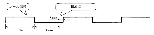
Tcomm=T0(180°−acomm)/180°
を計算することにより、時間Tcommを算出する。図2に示すように、この時間Tcommが、タイマをリセットして再始動させてから転流点に到達するまでの時間となっている。
IE=Ia1−Ia2
Ia1=IT1 かつ Ia2=IT2
である。
IE=IT1−IT2
IEa=Ia1−Ia2=IT1−IT2
IEb=Ib1−Ib2=IT3−IT4
IEa=0 又は、
IEb=0
IEa=Ia−0.5(Ib+Ic)
IEb=Ib−0.5(Ic+Ia)
IEc=Ic−0.5(Ia+Ib)
IEa=0 又は IEb=0 又は IEc
位相aについての例:
IEa=IT1−0.5(IT2+IT3)
IEa=Ia−0.5(Ib+Ic)
Ia+Ib+Ic=0
IEa=IEa+0
=IEa+λ(Ia+Ib+Ic)
=Ia−0.5(Ib+Ic)+λ(Ia+Ib+Ic)
IEa=1.5Ia
即ち、この場合には、転流角を決めるために条件Ia=0も利用することができる。
11 モータ制御部
20 転流信号
21 モータ電流
22 巻線電流
30 転流信号
31 モータ電流
32 巻線電流
40 転流信号
41 モータ電流
42 巻線電流
50 モータ(2コイル)
51 モータ制御部
60 モータ(4コイル)
61 モータ制御部
70 モータ(3コイル)
71 モータ制御部
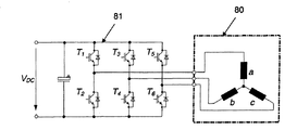
80 モータ(3コイル)
81 モータ制御部
Claims (5)
- ステータに対するロータの位置が検出され、それに基づいて転流信号(20)が生成され、転流信号に依存して、事前設定された転流が生じる電気角を示す転流角でモータ巻線(a)に通電が行われる、少なくとも一つのモータ巻線(a)を備えているブラシレス直流モータ(10,11)の転流方法において、
前記ロータの位置は、前記ステータの溝中央部に設けられた単数又は複数の位置センサにより検出され、前記位置センサに基づいて前記転流信号(20;30;40)が生成され、
前記転流信号(20;30;40)の発生時に巻線電流(22;32;42)の極性が検出され、転流角は、検出された巻線電流の極性に依存して、転流信号の発生時に巻線電流(I)が実質的にゼロになるように、又は、ゼロ通過を有するように変更されることを特徴とするブラシレス直流モータの転流方法。 - 巻線がバイポーラ通電される場合、転流信号の切換時に巻線電流(22)の極性が正であるとき、又は、転流信号の切換時に巻線電流(22)の極性が負であるとき、転流角が減少させられることを特徴とする請求項1に記載の方法。
- 巻線がバイポーラ通電される場合、転流信号の切換時に巻線電流(42)の極性が負であるとき、又は、転流信号の切換時に巻線電流(42)の極性が正であるとき、転流角が増加させられることを特徴とする請求項1に記載の方法。
- 巻線電流の値及び/又は極性が、対応するパワースイッチにおける電圧降下の測定によって検出されることを特徴とする請求項1乃至3のいずれか一項に記載の方法。
- ロータの位置が、前記ステータの溝中央部に設けられたホールセンサによって検出され、それに基づいて転流信号(20;30;40)が生成されることを特徴とする請求項1乃至4のいずれか一項に記載の方法。
Applications Claiming Priority (1)
| Application Number | Priority Date | Filing Date | Title |
|---|---|---|---|
| DE10346711A DE10346711A1 (de) | 2003-10-08 | 2003-10-08 | Verfahren zur Kommutierung eines bürstenlosen Gleichstrommotors |
Publications (2)
| Publication Number | Publication Date |
|---|---|
| JP2005117895A JP2005117895A (ja) | 2005-04-28 |
| JP4633433B2 true JP4633433B2 (ja) | 2011-02-16 |
Family
ID=34306319
Family Applications (1)
| Application Number | Title | Priority Date | Filing Date |
|---|---|---|---|
| JP2004296623A Expired - Fee Related JP4633433B2 (ja) | 2003-10-08 | 2004-10-08 | ブラシレス直流モータの転流方法 |
Country Status (4)
| Country | Link |
|---|---|
| US (1) | US7030583B2 (ja) |
| EP (1) | EP1523090A3 (ja) |
| JP (1) | JP4633433B2 (ja) |
| DE (1) | DE10346711A1 (ja) |
Families Citing this family (20)
| Publication number | Priority date | Publication date | Assignee | Title |
|---|---|---|---|---|
| SE526270C2 (sv) * | 2003-03-19 | 2005-08-09 | Forskarpatent I Syd Ab | Seriemagnetisering av synkronmotorer |
| DE10346711A1 (de) * | 2003-10-08 | 2005-05-25 | Minebea Co., Ltd. | Verfahren zur Kommutierung eines bürstenlosen Gleichstrommotors |
| DE102004001932B4 (de) * | 2004-01-14 | 2009-10-01 | Minebea Co., Ltd. | Verfahren zur Ansteuerung eines elektronisch kommutierten Motors und Motorsteuerung |
| EP1612923A1 (de) * | 2004-07-03 | 2006-01-04 | LuK Lamellen und Kupplungsbau Beteiligungs KG | Verfahren zum Messen der Drehzahl einer elektrischen Maschine |
| DE102005016333A1 (de) * | 2005-04-09 | 2006-10-12 | Minebea Co., Ltd. | Verfahren und Steuersystem zur Kommutierung eines einsträngigen bürstenlosen Motors |
| EP1734648B1 (de) * | 2005-06-13 | 2012-08-15 | Brose Fahrzeugteile GmbH & Co. KG, Würzburg | Asymmetrische Ansteuerung eines sensorlosen und bürstenlosen Elektromotors |
| US7423394B2 (en) * | 2006-01-12 | 2008-09-09 | Intelasense, Llc | Single-sensor based commutation of multi-phase motor |
| US7777436B2 (en) * | 2008-07-14 | 2010-08-17 | The Bergquist Torrington Company | Sensorless drive for unipolar three phase brushless DC motors |
| DE102008036704B4 (de) | 2008-08-07 | 2015-02-12 | Ulrich Clauss | Gleichstrom-Maschine mit elektronischer Kommutierung |
| DE102008057288A1 (de) * | 2008-11-14 | 2010-05-20 | Continental Automotive Gmbh | Steuervorrichtung für einen Motor und Verfahren zum Steuern des Motors |
| DE102010026021A1 (de) * | 2009-07-11 | 2011-01-13 | Ebm-Papst St. Georgen Gmbh & Co. Kg | Einphasiger elektronisch kommutierter Motor |
| US8773055B2 (en) * | 2010-01-12 | 2014-07-08 | Ebm-Papst St. Georgen Gmbh & Co. Kg | One-phase electronically commutated motor |
| DE102012024414A1 (de) | 2012-12-14 | 2014-06-18 | Minebea Co., Ltd. | Verdampfungshemmstoff zur Verwendung in einer Schmiermittelzusammensetzung in einem fluiddynamischen Lagersystem |
| US9385639B2 (en) | 2013-05-28 | 2016-07-05 | Stmicroelectronics S.R.L. | Switching controller for electric motors and related method of controlling electric motors |
| DE102013015361A1 (de) | 2013-09-16 | 2015-03-19 | Minebea Co., Ltd. | Additivzusammensetzung zur Verwendung in einer Schmiermittelzusammensetzung in einem fluiddynamischen Lagersystem |
| DE102013015360A1 (de) | 2013-09-16 | 2015-03-19 | Minebea Co., Ltd. | Additivzusammensetzung zur Verwendung in einer Schmiermittelzusammensetzung in einem fluiddynamischen Lagersystem |
| GB201317749D0 (en) | 2013-10-08 | 2013-11-20 | Dyson Technology Ltd | AC/DC boost converter |
| WO2015090386A1 (de) * | 2013-12-18 | 2015-06-25 | Siemens Aktiengesellschaft | Winkelgeber |
| DE102017214637A1 (de) * | 2017-08-22 | 2019-02-28 | Robert Bosch Gmbh | Verfahren zum Betrieb eines elektronisch kommutierten Elektromotors |
| DE102019209851A1 (de) * | 2019-07-04 | 2021-01-07 | Robert Bosch Gmbh | Handwerkzeugmaschine mit einem elektronisch kommutierten Motor |
Citations (2)
| Publication number | Priority date | Publication date | Assignee | Title |
|---|---|---|---|---|
| JP2002199778A (ja) * | 2000-12-27 | 2002-07-12 | Matsushita Electric Ind Co Ltd | モータ駆動装置 |
| JP2003219677A (ja) * | 2002-01-23 | 2003-07-31 | Toyota Motor Corp | 交流発電電動機用インバータ |
Family Cites Families (21)
| Publication number | Priority date | Publication date | Assignee | Title |
|---|---|---|---|---|
| USRE26622E (en) * | 1968-03-26 | 1969-07-01 | Synchronous motor control circuit | |
| DE2901676A1 (de) * | 1979-01-17 | 1980-08-14 | Papst Motoren Kg | Kollektorloser gleichstrommotor |
| CH658518A5 (de) * | 1982-09-04 | 1986-11-14 | Papst Motoren Gmbh & Co Kg | Sensorvorrichtung. |
| DE3517570A1 (de) * | 1985-05-15 | 1986-11-20 | Deutsche Thomson-Brandt Gmbh, 7730 Villingen-Schwenningen | Schaltung zur steuerung eines buerstenlosen elektromotors |
| US5003455A (en) * | 1990-08-14 | 1991-03-26 | Polyspede Electronics Corporation | Circuitry and method for controlling the firing of a thyristor |
| KR930004029B1 (ko) * | 1990-11-06 | 1993-05-19 | 주식회사 전연전기공업 | 트래피조이달(Trapezoidal) 구동형 무정류자 직류 전동기의 최적 정류회로 |
| JPH04185296A (ja) * | 1990-11-20 | 1992-07-02 | Seiko Epson Corp | 直流ブラシレスモータ制御装置 |
| KR100198294B1 (ko) * | 1996-06-20 | 1999-06-15 | 구자홍 | 비엘디씨 모터의 속도 제어 방법 |
| US5982122A (en) * | 1996-12-05 | 1999-11-09 | General Electric Company | Capacitively powered motor and constant speed control therefor |
| US6172498B1 (en) * | 1998-09-29 | 2001-01-09 | Rockwell Technologies, Llc | Method and apparatus for rotor angle detection |
| DE19860448A1 (de) * | 1998-12-28 | 2000-06-29 | Grundfos A S Bjerringbro | Verfahren zur Kommutierung eines elektronisch kommutierten bürstenlosen Mehrphasen-Permanentmagnetmotors |
| DE19860446A1 (de) * | 1998-12-28 | 2000-06-29 | Grundfos A S Bjerringbro | Verfahren zur Regelung eines spannungs-/frequenzumrichtergesteuerten Mehrphasen-Permanentmagnetmotors |
| DE59914199D1 (de) * | 1999-09-08 | 2007-03-29 | Melcher Rolf | Schaltungsanordnung zur Überwachung eines zum Steuern einer Last vorgesehenen elektronischen Schalters |
| DE19955248A1 (de) * | 1999-11-17 | 2001-05-31 | Bosch Gmbh Robert | Verfahren zur Verschiebung des Kommutierungszeitpunktes bei einem sensor- und bürstenlosen Gleichstrommotor sowie Anordnung zur Durchführung des Verfahrens |
| US6441572B2 (en) * | 1999-12-14 | 2002-08-27 | The Penn State Research Foundation | Detection of rotor angle in a permanent magnet synchronous motor at zero speed |
| DE10023370A1 (de) * | 2000-05-12 | 2001-11-22 | Mulfingen Elektrobau Ebm | System zur elektronischen Kommutierung eines bürstenlosen Gleichstrommotors |
| JP3674578B2 (ja) * | 2001-11-29 | 2005-07-20 | 株式会社デンソー | 三相インバータの電流検出装置 |
| US6847186B1 (en) * | 2002-10-18 | 2005-01-25 | Raser Technologies, Inc. | Resonant motor system |
| DE10346711A1 (de) * | 2003-10-08 | 2005-05-25 | Minebea Co., Ltd. | Verfahren zur Kommutierung eines bürstenlosen Gleichstrommotors |
| DE10355651B4 (de) * | 2003-11-28 | 2011-06-01 | Minebea Co., Ltd. | Verfahren zur Optimierung des Wirkungsgrades eines unter Last betriebenen Motors |
| US20050135794A1 (en) * | 2003-12-22 | 2005-06-23 | General Electric Company | Method and system for negative torque reduction in a brushless DC motor |
-
2003
- 2003-10-08 DE DE10346711A patent/DE10346711A1/de not_active Ceased
-
2004
- 2004-09-23 US US10/948,838 patent/US7030583B2/en active Active
- 2004-10-01 EP EP04023471A patent/EP1523090A3/de not_active Withdrawn
- 2004-10-08 JP JP2004296623A patent/JP4633433B2/ja not_active Expired - Fee Related
Patent Citations (2)
| Publication number | Priority date | Publication date | Assignee | Title |
|---|---|---|---|---|
| JP2002199778A (ja) * | 2000-12-27 | 2002-07-12 | Matsushita Electric Ind Co Ltd | モータ駆動装置 |
| JP2003219677A (ja) * | 2002-01-23 | 2003-07-31 | Toyota Motor Corp | 交流発電電動機用インバータ |
Also Published As
| Publication number | Publication date |
|---|---|
| US20050077854A1 (en) | 2005-04-14 |
| EP1523090A2 (de) | 2005-04-13 |
| US7030583B2 (en) | 2006-04-18 |
| JP2005117895A (ja) | 2005-04-28 |
| EP1523090A3 (de) | 2007-08-29 |
| DE10346711A1 (de) | 2005-05-25 |
Similar Documents
| Publication | Publication Date | Title |
|---|---|---|
| JP4633433B2 (ja) | ブラシレス直流モータの転流方法 | |
| JP6375431B2 (ja) | 永久磁石モータのロータ位置の決定方法 | |
| JP6065188B2 (ja) | 電気機械の制御 | |
| JP5310568B2 (ja) | インバータ制御装置と電動圧縮機および家庭用電気機器 | |
| JP2010541517A (ja) | インバータ制御装置とそれを用いたモータ駆動装置、電動圧縮機および家庭用電気機器 | |
| US8120297B2 (en) | Control of synchronous electrical machines | |
| JP2006136194A (ja) | ブラシレス直流モータ | |
| CN107317524B (zh) | 确定永磁电机的转子位置的方法 | |
| CN107395071B (zh) | 控制无刷永磁电机的方法 | |
| US7023173B2 (en) | Apparatus for driving brushless motor and method of controlling the motor | |
| JP5843955B2 (ja) | 単相交流永久磁石モータのセンサレス・ダイナミック駆動方法およびシステム | |
| TWI683531B (zh) | 單相直流無刷馬達僅於啟動運用感測器的驅動方法 | |
| EP3739745A1 (en) | Single-phase direct-current brushless motor and control apparatus and control method therefor | |
| JP5330728B2 (ja) | ブラシレスモータの駆動装置 | |
| KR102474670B1 (ko) | 스위치드 릴럭턴스 모터를 구동하는 구동 제어기 및 구동 제어 방법 | |
| JP2009011014A (ja) | インバータ制御装置と電動圧縮機および家庭用電気機器 | |
| KR102238456B1 (ko) | 스위치드 릴럭턴스 모터를 구동하는 구동 회로 | |
| KR102555790B1 (ko) | 무브러시 영구 자석 모터를 제어하는 방법 | |
| JP5326948B2 (ja) | インバータ制御装置と電動圧縮機および電気機器 | |
| KR100282366B1 (ko) | 센서리스 비엘디씨(bldc) 모터의 구동방법 | |
| KR102226615B1 (ko) | 스위치드 릴럭턴스 모터를 포함하는 모터 시스템의 동작 방법 | |
| JP2011055586A (ja) | モータ駆動制御回路 | |
| JPH08140391A (ja) | ブラシレスモータ駆動装置 | |
| JP3389300B2 (ja) | ブラシレスモータの運転方法 | |
| JP5995066B2 (ja) | 二相ブラシレスモータの制御装置 |
Legal Events
| Date | Code | Title | Description |
|---|---|---|---|
| A621 | Written request for application examination |
Free format text: JAPANESE INTERMEDIATE CODE: A621 Effective date: 20070803 |
|
| A131 | Notification of reasons for refusal |
Free format text: JAPANESE INTERMEDIATE CODE: A131 Effective date: 20100511 |
|
| A977 | Report on retrieval |
Free format text: JAPANESE INTERMEDIATE CODE: A971007 Effective date: 20100513 |
|
| A521 | Request for written amendment filed |
Free format text: JAPANESE INTERMEDIATE CODE: A523 Effective date: 20100712 |
|
| TRDD | Decision of grant or rejection written | ||
| A01 | Written decision to grant a patent or to grant a registration (utility model) |
Free format text: JAPANESE INTERMEDIATE CODE: A01 Effective date: 20101019 |
|
| A01 | Written decision to grant a patent or to grant a registration (utility model) |
Free format text: JAPANESE INTERMEDIATE CODE: A01 |
|
| A61 | First payment of annual fees (during grant procedure) |
Free format text: JAPANESE INTERMEDIATE CODE: A61 Effective date: 20101117 |
|
| R150 | Certificate of patent or registration of utility model |
Free format text: JAPANESE INTERMEDIATE CODE: R150 |
|
| FPAY | Renewal fee payment (event date is renewal date of database) |
Free format text: PAYMENT UNTIL: 20131126 Year of fee payment: 3 |
|
| R250 | Receipt of annual fees |
Free format text: JAPANESE INTERMEDIATE CODE: R250 |
|
| LAPS | Cancellation because of no payment of annual fees |