JP4631985B2 - Beverage extractor - Google Patents
Beverage extractor Download PDFInfo
- Publication number
- JP4631985B2 JP4631985B2 JP2009200065A JP2009200065A JP4631985B2 JP 4631985 B2 JP4631985 B2 JP 4631985B2 JP 2009200065 A JP2009200065 A JP 2009200065A JP 2009200065 A JP2009200065 A JP 2009200065A JP 4631985 B2 JP4631985 B2 JP 4631985B2
- Authority
- JP
- Japan
- Prior art keywords
- paper
- filter
- extraction
- unit
- roll
- Prior art date
- Legal status (The legal status is an assumption and is not a legal conclusion. Google has not performed a legal analysis and makes no representation as to the accuracy of the status listed.)
- Active
Links
Images


Landscapes
- Apparatus For Making Beverages (AREA)
- Beverage Vending Machines With Cups, And Gas Or Electricity Vending Machines (AREA)
Description
本発明は、カップ式自動販売機や飲料ディスペンサなどに内蔵され、コーヒー豆や茶葉などの原料を用いてコーヒーや茶系飲料などを抽出する飲料抽出装置に関する。 The present invention relates to a beverage extraction apparatus that is incorporated in a cup-type vending machine, a beverage dispenser, and the like and extracts coffee, tea-based beverages, and the like using raw materials such as coffee beans and tea leaves.
一般に、この種の飲料抽出装置として、抽出された飲料をろ過するために、連続するペーパーフィルタを用いたものと、繰り返し使用されるいわゆるパーマネントフィルタを用いたものがある。従来、前者の飲料抽出装置(以下、適宜「ペーパー抽出装置」という)として、例えば特許文献1に開示されたものが知られており、後者の飲料抽出装置(以下、適宜「ペーパーレス抽出装置」という)として、例えば本出願人がすでに出願した特許文献2に開示されたものが知られている。
Generally, as this type of beverage extraction device, there are one using a continuous paper filter and another using a so-called permanent filter which is repeatedly used to filter the extracted beverage. Conventionally, as the former beverage extraction device (hereinafter referred to as “paper extraction device” as appropriate), for example, the one disclosed in
特許文献1のペーパー抽出装置は、下面が開放し、供給された原料および湯によって内部で飲料を抽出するシリンダと、その下方において昇降自在に設けられたフィルタブロックと、シリンダとフィルタブロックの間にペーパーフィルタを送り出すペーパー送出し機構などを備えている。一方、特許文献2のペーパーレス抽出装置は、上記と同様のシリンダと、上面にパーマネントフィルタを有し、シリンダの下方において昇降自在に設けられたフィルタブロックと、パーマネントフィルタ上に残留した抽出滓を排出するためのスクレーパなどを備えている。
In the paper extraction device of
一般に、ペーパー抽出装置では、ペーパーフィルタによって、シリンダ内で抽出された飲料をろ過することにより、通常サイズの粉や葉などの原料はもちろん、原料に含まれる微粉も除去でき、残渣がほとんど無い、高品質の飲料を提供できるという利点がある。一方、ペーパーレス抽出装置では、ペーパー送出し機構を備えていない分、装置全体をコンパクトに構成できるとともに、ペーパーフィルタが不要な分、ランニングコストを抑制できるという利点がある。加えて、ペーパーフィルタの廃棄や交換が不要な分、オペレータにとって、抽出装置の操作を簡易化できるという利点もある。このように、ペーパー抽出装置およびペーパーレス抽出装置には、それぞれの特性に応じた利点がある。そのため、カップ式自動販売機や飲料ディスペンサなどの飲料提供機器では、その製造時に、飲料提供機器の種類や、提供すべき飲料の種類、品質などに応じて選択された抽出装置が搭載される。 In general, in a paper extraction device, by filtering a beverage extracted in a cylinder with a paper filter, not only raw materials such as normal size powder and leaves, but also fine powder contained in the raw material can be removed, and there is almost no residue. There is an advantage that a high quality beverage can be provided. On the other hand, the paperless extraction apparatus has an advantage that the entire apparatus can be configured compactly because the paper feeding mechanism is not provided, and the running cost can be suppressed because the paper filter is unnecessary. In addition, since there is no need to discard or replace the paper filter, there is also an advantage that the operation of the extraction device can be simplified for the operator. Thus, the paper extraction device and the paperless extraction device have advantages according to their characteristics. Therefore, in beverage providing devices such as cup-type vending machines and beverage dispensers, an extraction device selected according to the type of beverage providing device, the type of beverage to be provided, the quality, and the like is mounted.
しかし、ペーパー抽出装置およびペーパーレス抽出装置は、それぞれが専用品として製造されるため、両者の製造や将来のバージョンアップに備えた開発が別々に行われ、不経済である。また、ペーパー抽出装置およびペーパーレス抽出装置の一方を飲料提供機器に搭載した後における他方への変更は、飲料提供機器内のスペースや制御の関係上、非常に困難である。 However, since each of the paper extraction device and the paperless extraction device is manufactured as a dedicated product, development for both manufacture and future version upgrade is performed separately, which is uneconomical. Moreover, it is very difficult to change to the other after one of the paper extraction device and the paperless extraction device is mounted on the beverage providing device because of space and control in the beverage providing device.
本発明は、以上のような課題を解決するためになされたものであり、搭載すべき飲料提供機器の種類や提供すべき飲料の品質などに応じ、抽出装置本体に取付け可能なペーパーフィルタ送出し装置の有無を選択することにより、多種類の飲料提供機器に柔軟に対応でき、その結果、飲料を抽出によって調理する装置としての統一化を図ることができる飲料抽出装置を提供することを目的とする。 The present invention has been made in order to solve the above-described problems, and is capable of delivering a paper filter that can be attached to the main body of an extraction device according to the type of beverage providing device to be mounted and the quality of the beverage to be provided. It is an object of the present invention to provide a beverage extraction device that can flexibly cope with various types of beverage providing devices by selecting the presence or absence of a device, and as a result, can be unified as a device for cooking beverages by extraction. To do.
上記の目的を達成するために、請求項1に係る発明は、原料および水を用いて飲料を抽出するための飲料抽出装置であって、下面が開放するとともに原料および水が供給される抽出容器と、この抽出容器の下方に昇降自在に設けられ、抽出容器内で抽出された飲料をろ過しながら搬出する際に、抽出容器の下面をシールした状態で繰り返し使用されるパーマネントフィルタと、を有する抽出装置本体と、パーマネントフィルタよりもろ過の度合が高く、飲料をろ過するとともに、パーマネントフィルタの上側に残留した抽出後の原料である抽出滓を排出するための連続するペーパーフィルタを保持し、ペーパーフィルタを抽出容器とパーマネントフィルタの間に送り出し可能に構成されたペーパーフィルタ送出し装置と、を備え、ペーパーフィルタ送出し装置は、抽出装置本体に着脱自在に構成されるとともに、抽出装置本体に選択的に取り付けられることを特徴とする。
In order to achieve the above object, the invention according to
この構成によれば、飲料抽出装置は、上記の抽出装置本体およびペーパーフィルタ送出し装置を備えており、ペーパーフィルタ送出し装置が、抽出装置本体に対し、着脱自在に構成されるとともに、選択的に取り付けられる。 According to this configuration, the beverage extraction device includes the extraction device body and the paper filter delivery device, and the paper filter delivery device is configured to be detachable from the extraction device body and is selectively Attached to.
抽出装置本体にペーパーフィルタ送出し装置が取り付けられた飲料抽出装置では、抽出容器に原料および水が供給され、その抽出容器内で抽出された飲料が、抽出容器の下面をシールするパーマネントフィルタに加えて、ペーパーフィルタによってもろ過され、搬出される。この飲料抽出装置では、原料の残渣がほとんど無い、高品質の飲料を得ることができる。したがって、例えば、高品質の飲料の提供が求められる飲料提供機器などに搭載するのに適した飲料抽出装置を得ることができる。 In a beverage extraction device with a paper filter delivery device attached to the main body of the extraction device, raw materials and water are supplied to the extraction container, and the beverage extracted in the extraction container is added to the permanent filter that seals the lower surface of the extraction container. Then, it is filtered by a paper filter and carried out. In this beverage extraction apparatus, a high-quality beverage with almost no raw material residue can be obtained. Therefore, for example, it is possible to obtain a beverage extraction device suitable for being mounted on a beverage providing device that is required to provide a high-quality beverage.
一方、抽出装置本体にペーパーフィルタ送出し装置が取り付けられていない飲料抽出装置では、抽出容器内で抽出された飲料が、パーマネントフィルタによってろ過されながら搬出される。この飲料抽出装置では、ペーパーフィルタ送出し装置が無い分、飲料抽出装置全体をコンパクトに構成できるとともに、ペーパーフィルタが不要な分、ランニングコストを低減でき、加えて、ペーパーフィルタの廃棄や交換が不要な分、オペレータにとって、装置の操作を簡易化できる。したがって、例えば、比較的小さな飲料提供機器や操作が簡単な飲料提供機器などに搭載するのに適した飲料抽出装置を得ることができる。 On the other hand, in the beverage extraction device in which the paper filter delivery device is not attached to the extraction device body, the beverage extracted in the extraction container is carried out while being filtered by the permanent filter. In this beverage extraction device, the entire beverage extraction device can be made compact as much as there is no paper filter delivery device, and the running cost can be reduced by eliminating the need for the paper filter, and in addition, disposal and replacement of the paper filter is unnecessary. The operation of the device can be simplified for the operator. Therefore, for example, a beverage extraction device suitable for mounting on a relatively small beverage providing device or a beverage providing device that is easy to operate can be obtained.
以上のように、本発明の飲料抽出装置によれば、搭載すべき飲料提供機器の種類や提供すべき飲料の品質などに応じ、抽出装置本体に取付け可能なペーパーフィルタ送出し装置の有無を選択することにより、多種類の飲料提供機器に柔軟に対応でき、その結果、飲料を抽出によって調理する装置としての統一化を図ることができる。 As described above, according to the beverage extraction device of the present invention, the presence or absence of the paper filter delivery device that can be attached to the extraction device body is selected according to the type of beverage providing device to be mounted, the quality of the beverage to be provided, and the like. By doing so, it can respond flexibly to various types of beverage providing devices, and as a result, it can be unified as an apparatus for cooking beverages by extraction.
請求項2に係る発明は、請求項1に記載の飲料抽出装置において、抽出装置本体は、抽出滓を排出する抽出滓排出手段を、さらに有しており、抽出装置本体およびペーパーフィルタ送出し装置を制御するための制御装置を、さらに備え、制御装置は、ペーパーフィルタ送出し装置が抽出装置本体に取り付けられているときに、ペーパーフィルタ送出し装置を制御することによって、抽出滓を排出し、ペーパーフィルタ送出し装置が抽出装置本体に取り付けられていないときに、抽出滓排出手段を制御することによって抽出滓を排出することを特徴とする。 According to a second aspect of the present invention, in the beverage extraction device according to the first aspect, the main body of the extraction device further includes an extraction basket discharging means for discharging the extraction basket, and the extraction device main body and the paper filter delivery device A control device for controlling the paper filter, and the control device discharges the extraction soot by controlling the paper filter delivery device when the paper filter delivery device is attached to the extraction device body, When the paper filter delivery device is not attached to the extraction device main body, the extraction soot is discharged by controlling the extraction soot discharging means.
この構成によれば、抽出装置本体が、抽出滓を排出する抽出滓排出手段を有しており、抽出装置本体およびペーパーフィルタ送出し装置が、制御装置によって制御される。この制御装置は、ペーパーフィルタ送出し装置が抽出装置本体に取り付けられているときに、ペーパーフィルタ送出し装置を制御することによって、抽出滓を排出する一方、ペーパーフィルタ送出し装置が取り付けられていないときに、上記抽出滓排出手段を制御することによって、抽出滓を排出する。このように、ペーパーフィルタ送出し装置の有無にかかわらず、単一の制御装置によって、抽出滓の排出を確実に行うことができる。 According to this configuration, the extraction device main body has the extraction tub discharge means for discharging the extraction tub, and the extraction device main body and the paper filter delivery device are controlled by the control device. This control device, when the paper filter delivery device is attached to the extraction device main body, controls the paper filter delivery device to discharge the extraction soot, while the paper filter delivery device is not attached. Sometimes, the extracted soot is discharged by controlling the extracted soot discharging means. Thus, regardless of the presence or absence of the paper filter delivery device, the extraction basket can be reliably discharged by a single control device.
請求項3に係る発明は、請求項1または2に記載の飲料抽出装置において、抽出装置本体は、パーマネントフィルタを駆動するための第1駆動源を有する本体駆動ユニットと、この本体駆動ユニットに着脱自在に取り付けられ、抽出容器およびパーマネントフィルタを支持する抽出ユニットと、で構成されており、本体駆動ユニットは、第1駆動源の周囲を覆った状態で、本体駆動ユニットの外郭を構成するケースを、さらに有していることを特徴とする。 According to a third aspect of the present invention, in the beverage extraction device according to the first or second aspect, the extraction device body includes a main body drive unit having a first drive source for driving the permanent filter, and is attached to and detached from the main body drive unit. And an extraction unit that is freely attached and supports the extraction container and the permanent filter, and the main body drive unit has a case that constitutes an outline of the main body drive unit in a state of covering the periphery of the first drive source. , And further comprising.
この構成によれば、抽出装置本体が、本体駆動ユニットおよび抽出ユニットで構成され、抽出ユニットが本体駆動ユニットに着脱自在に取り付けられている。本体駆動ユニットは、パーマネントフィルタを駆動するための第1駆動源を有する一方、抽出ユニットは、抽出容器およびパーマネントフィルタを支持している。つまり、実質的な飲料の抽出は、抽出容器およびパーマネントフィルタを支持する抽出ユニットにおいて行われる。飲料の抽出が繰り返し行われることにより、抽出容器やパーマネントフィルタに汚れが堆積するので、これらを洗浄などする際に、抽出ユニットを本体駆動ユニットから取り外し、簡単に洗浄を行うことができる。 According to this configuration, the extraction apparatus main body includes the main body drive unit and the extraction unit, and the extraction unit is detachably attached to the main body drive unit. The main body drive unit has a first drive source for driving the permanent filter, while the extraction unit supports the extraction container and the permanent filter. In other words, substantial beverage extraction is performed in an extraction unit that supports the extraction container and the permanent filter. As the beverage is repeatedly extracted, dirt accumulates in the extraction container and the permanent filter. Therefore, when these are washed, the extraction unit can be removed from the main body drive unit and can be easily washed.
また、本体駆動ユニットは、その外郭を構成するケースを有しており、このケースによって、第1駆動源が覆われている。一般に、カップ式自動販売機などの飲料提供機器では、内部の清掃のために、水を供給するいわゆるリンスバルブが設けられていることが多い。したがって、本体駆動ユニットが飲料提供機器内に固定されている場合などに、リンスバルブを利用して、外部から水をかけ、内部の第1駆動源を濡らすことなく、本体駆動ユニットの外側を洗浄することができる。 Moreover, the main body drive unit has a case that constitutes the outline thereof, and the first drive source is covered by this case. In general, a beverage providing device such as a cup-type vending machine is often provided with a so-called rinse valve for supplying water for cleaning the inside. Therefore, when the main unit drive unit is fixed in the beverage supply device, the outside of the main unit drive unit is washed without applying water from the outside and wetting the first drive source inside using the rinse valve. can do.
請求項4に係る発明は、請求項1ないし3のいずれかに記載の飲料抽出装置において、ペーパーフィルタは、ロール状に巻かれたロール部を有しており、ペーパーフィルタ送出し装置は、第2駆動源を有するペーパー駆動ユニットと、ペーパーフィルタのロール部を回転自在に保持するホルダ部と、第2駆動源で駆動されることによって、ホルダ部からペーパーフィルタを引き出し、抽出容器とパーマネントフィルタの間に送り出す送出し機構と、を有するペーパーホルダユニットと、で構成されていることを特徴とする。
The invention according to
この構成によれば、ペーパーフィルタ送出し装置が、ペーパー駆動ユニットおよびペーパーホルダユニットで構成されている。ペーパー駆動ユニットは、第2駆動源を有する一方、ペーパーホルダユニットは、ペーパーフィルタのロール部を回転自在に保持するホルダ部、およびこのホルダ部からペーパーフィルタを引き出し、抽出容器とパーマネントフィルタの間に送り出す送出し機構を有している。また、この送出し機構は、ペーパー駆動ユニット側の第2駆動源によって駆動される。このように、ペーパーフィルタ送出し装置が、ペーパーフィルタの保持・送出し機能を有するペーパーホルダユニットと、駆動機能を有するペーパー駆動ユニットとで、ユニット化されることにより、故障などの際のメンテナンスや交換をユニットごとに容易に行うことができる。 According to this configuration, the paper filter delivery device is configured by the paper drive unit and the paper holder unit. While the paper drive unit has a second drive source, the paper holder unit holds the roll part of the paper filter in a rotatable manner, and pulls out the paper filter from the holder part between the extraction container and the permanent filter. A delivery mechanism is provided. The feeding mechanism is driven by a second drive source on the paper drive unit side. In this way, the paper filter sending device is unitized by the paper holder unit having the paper filter holding / feeding function and the paper driving unit having the driving function. Replacement can be easily performed for each unit.
請求項5に係る発明は、請求項4に記載の飲料抽出装置において、ペーパー駆動ユニットおよびペーパーホルダユニットは、互いに着脱自在に構成されていることを特徴とする。
The invention according to
この構成によれば、ペーパー駆動ユニットおよびペーパーホルダユニットが、互いに着脱自在に構成されているので、上述したユニットごとのメンテナンスや交換を、より一層容易に行うことができる。 According to this configuration, since the paper drive unit and the paper holder unit are configured to be detachable from each other, the above-described maintenance and replacement for each unit can be performed more easily.
請求項6に係る発明は、請求項5に記載の飲料抽出装置において、ペーパー駆動ユニットは、スイッチと、このスイッチを、ON状態に切り替えるON切替え位置と、OFF状態に切り替えるOFF切替え位置とに移動自在の切替えレバーと、この切替えレバーをON切替え位置側に付勢する付勢手段と、をさらに有し、ペーパーホルダユニットは、ペーパーフィルタがペーパー切れであるか否かを検出するためのペーパー切れ検出レバーを、さらに有し、ペーパー切れ検出レバーは、切替えレバーに係合するとともに、ペーパーフィルタのロール部の外周面に当接し、ペーパーフィルタの使用に伴って径が縮小するロール部に追従しながら移動可能に構成され、ロール部が所定の径に達するまで、切替えレバーを、付勢手段の付勢力に抗して、OFF切替え位置側に押圧し、ロール部が所定の径に達したときに、切替えレバーがON切替え位置に位置するのを許容することを特徴とする。 According to a sixth aspect of the present invention, in the beverage extraction device according to the fifth aspect, the paper drive unit moves to a switch, an ON switching position for switching the switch to the ON state, and an OFF switching position for switching to the OFF state. The paper holder unit further includes a flexible switching lever and a biasing means that biases the switching lever toward the ON switching position, and the paper holder unit detects whether the paper filter is out of paper or not. It further has a detection lever. The paper breakage detection lever engages with the switching lever and abuts the outer peripheral surface of the roll portion of the paper filter, and follows the roll portion whose diameter is reduced as the paper filter is used. The switching lever is resisted against the urging force of the urging means until the roll part reaches a predetermined diameter. Presses a position side OFF switch, when the roll unit has reached a predetermined diameter, characterized in that to allow the switching lever is positioned at the ON switching position.
この構成によれば、ペーパー駆動ユニットは、スイッチ、切替えレバーおよび付勢手段を有している。切替えレバーは、スイッチを、ON状態に切り替えるON切替え位置と、OFF状態に切り替えるOFF切替え位置とに移動自在に構成され、付勢手段によって、ON切替え位置側に付勢されている。一方、ペーパーホルダユニットは、ペーパー切れ検出レバーを有しており、このペーパー切れ検出レバーが、切替えレバーに係合するとともに、ペーパーフィルタのロール部の外周面に当接し、ペーパーフィルタの使用に伴って径が縮小するロール部に追従しながら移動可能に構成されている。また、ペーパー切れ検出レバーは、ロール部が所定の径、例えば、ペーパー切れであると判断される程度に残量が少なくなったロール部の径に達するまで、付勢手段の付勢力に抗して、切替えレバーをOFF切替え位置側に押圧する。この場合、スイッチがOFF状態となることで、ペーパー切れでないと判別することが可能である。一方、ペーパー切れ検出レバーは、ロール部が所定の径に達したときに、切替えレバーがON切替え位置に位置するのを許容する。この場合、スイッチがON状態となることで、ペーパー切れであると判別することが可能となる。以上のように、ペーパー駆動ユニット側のスイッチのON/OFF状態によって、ペーパーフィルタのペーパー切れを簡単かつ確実に判別することができる。 According to this configuration, the paper drive unit has the switch, the switching lever, and the urging means. The switching lever is configured to be movable between an ON switching position where the switch is switched to the ON state and an OFF switching position where the switch is switched to the OFF state, and is biased toward the ON switching position by the biasing means. On the other hand, the paper holder unit has a paper breakage detection lever. The paper breakage detection lever engages with the switching lever and abuts on the outer peripheral surface of the roll portion of the paper filter. Thus, it is configured to be movable while following the roll portion whose diameter is reduced. Further, the paper breakage detection lever resists the urging force of the urging means until the roll portion reaches a predetermined diameter, for example, the diameter of the roll portion whose remaining amount has decreased to such an extent that it is determined that the paper is out of paper. Then, press the switching lever toward the OFF switching position. In this case, when the switch is turned off, it can be determined that the paper has not run out. On the other hand, the paper breakage detection lever allows the switching lever to be positioned at the ON switching position when the roll portion reaches a predetermined diameter. In this case, when the switch is turned on, it can be determined that the paper is out. As described above, it is possible to easily and reliably determine whether the paper filter has run out of paper, based on the ON / OFF state of the switch on the paper drive unit side.
請求項7に係る発明は、請求項6に記載の飲料抽出装置において、ペーパー切れ検出レバーは、ペーパーホルダユニットがペーパー駆動ユニットに適正に取り付けられたときに、付勢手段の付勢力に抗して、切替えレバーをOFF切替え位置側に押圧することを特徴とする。
The invention according to
この構成によれば、ペーパーホルダユニットがペーパー駆動ユニットに適正に取り付けられたときに、ペーパー切れ検出レバーが、付勢手段の付勢力に抗して、切替えレバーをOFF切替え位置側に押圧する。この場合、スイッチはOFF状態となる。逆に言うと、ペーパーホルダユニットがペーパー駆動ユニットに適正に取り付けられていない状態は、ペーパーホルダユニットがペーパー駆動ユニットから取り外されることで、ペーパーホルダユニット側のペーパー切れ検出レバーが、ペーパー駆動ユニット側の切替えレバーから離れ、両者の係合が解除された状態と同じになる。この場合、ペーパー駆動ユニットにおいては、切替えレバーが付勢手段でON切替え位置側に付勢されるために、スイッチがON状態となる。つまり、ペーパーホルダユニットをペーパー駆動ユニットに取り付けたときに、本来、スイッチがOFF状態になるはずであるのに、スイッチが、ペーパーホルダユニットの取付け前と同様、ON状態に維持されることで、ペーパーホルダユニットが適正に取り付けられていないと判別することが可能である。以上のように、上記の構成によれば、ペーパー切れ検出レバーを利用して、ペーパーホルダユニットがペーパー駆動ユニットに適正に取り付けられているか否かを、容易に判別することができる。 According to this configuration, when the paper holder unit is properly attached to the paper drive unit, the paper breakage detection lever presses the switching lever toward the OFF switching position against the biasing force of the biasing means. In this case, the switch is turned off. Conversely, when the paper holder unit is not properly attached to the paper drive unit, the paper holder unit is removed from the paper drive unit so that the paper breakage detection lever on the paper holder unit side This is the same as the state where the engagement between the two is released. In this case, in the paper drive unit, the switch is turned on because the switch lever is biased to the ON switch position side by the biasing means. In other words, when the paper holder unit is attached to the paper drive unit, the switch should originally be in the OFF state, but the switch is maintained in the ON state as before the paper holder unit is attached. It is possible to determine that the paper holder unit is not properly attached. As described above, according to the above configuration, it is possible to easily determine whether or not the paper holder unit is properly attached to the paper drive unit using the paper breakage detection lever.
請求項8に係る発明は、請求項4ないし7のいずれかに記載の飲料抽出装置において、ペーパーホルダユニットは、下面が開放し、ペーパーフィルタのロール部を、その中心軸線が左右方向に延びるように収容するロール部収容ケースと、このロール部収容ケースの左右の側壁に、ロール部収容ケースの内部に対して出没自在にかつ内方に突出するように設けられ、ロール部の左右の端面の中央部に係合した状態で、ロール部を回転自在に支持する左右のロール部支持部材と、を備え、左右のロール部支持部材はいずれも、ロール部がロール部収容ケースに対して着脱される際に、ロール部の左右の端面で押圧されることによって、ロール部収容ケースの対応する側壁側に退避するように構成されていることを特徴とする。
The invention according to
この構成によれば、ペーパーフィルタのロール部を収容するロール部収容ケースは、下面が開放しており、ロール部を、その中心軸線が左右方向に延びるように収容する。また、ロール部収容ケースの左右の側壁には、ロール部収容ケースの内部に対して出没自在にかつ内方に突出する左右のロール部支持部材が設けられており、これらのロール部支持部材により、ロール部の左右の端面の中央部に係合した状態で、ロール部が回転自在に支持される。 According to this structure, the roll part accommodation case which accommodates the roll part of a paper filter is open | released in the lower surface, and accommodates a roll part so that the center axis line may extend in the left-right direction. The left and right side walls of the roll unit accommodation case are provided with left and right roll unit support members that protrude and inwardly protrude with respect to the inside of the roll unit storage case. The roll part is rotatably supported in a state of being engaged with the center part of the left and right end faces of the roll part.
ペーパーフィルタのロール部をロール部収容ケースにセットする場合、ロール部収容ケースの下方からその内部に挿入する。この場合、左右のロール部支持部材は、ロール部の左右の端面で押圧され、対応する側壁側に退避する。そして、ロール部の左右の端面の中央部がロール部支持部材の位置に達したときに、ロール部による左右のロール部支持部材の押圧が解除されることで、退避していた両ロール部支持部材が内方に戻り、ロール部を支持する。このように、ペーパーフィルタのロール部をセットする場合、ロール部をロール部収容ケースに下方から挿入するだけで、ロール部のセットを行うことができる。一方、ペーパーフィルタの交換の際に、そのロール部をロール部収容ケースから取り外す場合、ロール部をロール部収容ケース内において上下方向に若干動かし、上記の場合と同様にして、ロール部の左右の端面で左右のロール部支持部材を押圧し、側壁側に退避させる。そして、この状態のまま、ロール部を下方に引き抜くだけで、ロール部を取り外すことができる。以上のように、ペーパーホルダユニットに対するペーパーフィルタのロール部のセットおよび取外しを簡単に行うことができる。 When setting the roll part of a paper filter in a roll part accommodation case, it inserts into the inside from the downward direction of a roll part accommodation case. In this case, the left and right roll part support members are pressed by the left and right end faces of the roll part and retract to the corresponding side wall side. And when the center part of the left and right end surfaces of the roll part reaches the position of the roll part support member, both roll part supports that have been retracted are released by releasing the pressing of the left and right roll part support members by the roll part. The member returns inward to support the roll part. Thus, when setting the roll part of a paper filter, a roll part can be set only by inserting a roll part into a roll part accommodation case from the downward direction. On the other hand, when removing the roll unit from the roll unit storage case when replacing the paper filter, the roll unit is slightly moved up and down in the roll unit storage case, and in the same manner as described above, The left and right roll support members are pressed at the end surfaces and retracted to the side wall side. And a roll part can be removed only by pulling a roll part below in this state. As described above, it is possible to easily set and remove the roll portion of the paper filter with respect to the paper holder unit.
請求項9に係る発明は、請求項4ないし8のいずれかに記載の飲料抽出装置において、ペーパーフィルタ送出し装置が抽出装置本体の下側に取り付けられた状態において、ペーパーフィルタは、抽出装置本体の内部を通り、抽出装置本体の前側において垂下するようにセットされることを特徴とする。
The invention according to
この構成によれば、抽出時に使用されたペーパーフィルタが、抽出装置本体の前側において垂下するので、例えば、オペレータがペーパーフィルタから使用済み部分を切り離す際に、その切離し作業を抽出装置本体の前側において簡単に行うことができる。 According to this configuration, the paper filter used at the time of extraction hangs down on the front side of the extraction device body.For example, when the operator separates the used part from the paper filter, the separation work is performed on the front side of the extraction device body. It can be done easily.
請求項10に係る発明は、請求項9に記載の飲料抽出装置において、抽出装置本体には、ペーパーフィルタをセットする際に、ペーパーフィルタが、抽出装置本体の下方から手動で挿し入れながら送られることにより、ペーパーフィルタの先端部を、抽出装置本体の内部に案内し、さらに、抽出容器とパーマネントフィルタの間を通って、抽出装置本体の前方に到達するように案内するペーパーガイド部材が設けられていることを特徴とする。
The invention according to
この構成によれば、ペーパーフィルタをセットする際に、そのペーパーフィルタを抽出装置本体の下方から手動で挿し入れながら送る。このペーパーフィルタは、ペーパーガイド部材により、抽出装置本体の内部に案内され、さらに、抽出容器とパーマネントフィルタの間を通って、抽出装置本体の前方に到達するように案内される。これにより、抽出装置本体へのペーパーフィルタのセットを簡単に行うことができる。 According to this configuration, when the paper filter is set, the paper filter is sent while being manually inserted from below the extraction device body. The paper filter is guided inside the extraction apparatus main body by a paper guide member, and is further guided to reach the front of the extraction apparatus main body through the space between the extraction container and the permanent filter. Thereby, the paper filter can be easily set on the extraction apparatus main body.
請求項11に係る発明は、請求項9または10に記載の飲料抽出装置において、送出し機構は、第2駆動源によって駆動され、ペーパーホルダユニットの前端部に回転自在に設けられたペーパー送りローラと、このペーパー送りローラの前方に回転自在に設けられ、ペーパー送りローラとの間に、ペーパーフィルタの抽出装置本体の前側に垂下する部分を挟持するペーパー挟持ローラと、を有することを特徴とする。 According to an eleventh aspect of the present invention, in the beverage extraction apparatus according to the ninth or tenth aspect, the feeding mechanism is driven by the second drive source, and is a paper feed roller rotatably provided at the front end portion of the paper holder unit. And a paper clamping roller that is rotatably provided in front of the paper feeding roller and clamps a portion of the paper filter that hangs down to the front side of the main body of the extraction device. .
この構成によれば、ペーパーホルダユニットの前端部に回転自在に設けられたペーパー送りローラと、このペーパー送りローラの前方に回転自在に設けられたペーパー挟持ローラとによって、ペーパーフィルタの抽出装置本体の前側に垂下する部分を挟持する。そして、第2駆動源によって、ペーパー送りローラが所定方向に回転駆動されることにより、両ローラでペーパーフィルタを挟持しながら送り出す。これにより、ペーパーフィルタの使用済み部分を下方に送り出すとともに、次回の飲料の抽出に備えて、ロール部収容ケース内のロール部からペーパーフィルタを引き出し、ペーパーフィルタの使用済み部分に続く未使用部分を、抽出容器とパーマネントフィルタの間に移動させることができる。 According to this configuration, the paper filter extraction device main body is provided by the paper feed roller rotatably provided at the front end portion of the paper holder unit and the paper clamping roller rotatably provided in front of the paper feed roller. Hold the part that hangs forward. Then, the paper feed roller is rotationally driven in a predetermined direction by the second drive source, so that the paper filter is fed while being sandwiched by both rollers. As a result, the used part of the paper filter is sent downward, and in preparation for the next beverage extraction, the paper filter is pulled out from the roll part in the roll part containing case, and the unused part following the used part of the paper filter is removed. It can be moved between the extraction vessel and the permanent filter.
請求項12に係る発明は、請求項11に記載の飲料抽出装置において、送出し機構は、ペーパー挟持ローラを回転自在に支持し、ペーパー挟持ローラを、ペーパー送りローラ側に押圧する押圧位置と、ペーパー送りローラから離隔する離隔位置との間で移動可能に構成されたペーパー挟持ローラ支持部材を、さらに有していることを特徴とする。 According to a twelfth aspect of the present invention, in the beverage extraction device according to the eleventh aspect, the delivery mechanism rotatably supports the paper sandwiching roller, and a pressing position that presses the paper sandwiching roller toward the paper feed roller. It further has a paper nipping roller support member configured to be movable between a separation position separated from the paper feed roller.
この構成によれば、ペーパー挟持ローラがペーパー挟持ローラ支持部材に回転自在に支持され、このペーパー挟持ローラ支持部材が、上記押圧位置と離隔位置との間で移動可能に構成されている。ペーパーフィルタをペーパー送りローラとペーパー挟持ローラの間に挟んだ状態にセットする際に、ペーパー挟持ローラ支持部材を離隔位置に移動させることにより、両ローラ間に比較的大きなスペースを確保でき、そのスペースにペーパーフィルタを通した後で、ペーパー挟持ローラ支持部材を押圧位置に移動させることにより、ペーパーフィルタの両ローラ間のセットを簡単に行うことができる。 According to this configuration, the paper clamping roller is rotatably supported by the paper clamping roller support member, and the paper clamping roller support member is configured to be movable between the pressing position and the separation position. When setting the paper filter so that it is sandwiched between the paper feed roller and the paper clamping roller, a relatively large space can be secured between both rollers by moving the paper clamping roller support member to the separation position. After passing the paper filter through the paper filter, the paper nipping roller support member is moved to the pressing position, whereby the paper filter can be easily set between both rollers.
請求項13に係る発明は、請求項12に記載の飲料抽出装置において、ペーパー挟持ローラ支持部材は、押圧位置に位置するときに、ペーパー挟持ローラの上側に位置するとともに、ペーパーフィルタの抽出装置本体の前側に垂下する部分に前方から当接し、ペーパーフィルタから抽出滓を分離するための抽出滓分離部を有していることを特徴とする。 According to a thirteenth aspect of the present invention, in the beverage extraction device according to the twelfth aspect, when the paper clamping roller support member is located at the pressing position, the paper clamping roller support member is located above the paper clamping roller, and the paper filter extraction device body. It has a feature that it has an extraction basket separating portion for coming into contact with the front part of the paper and separating the extraction basket from the paper filter.
この構成によれば、ペーパー挟持ローラ支持部材が抽出滓分離部を有しており、この抽出滓分離部は、ペーパー挟持ローラ支持部材が押圧位置に位置するときに、ペーパー挟持ローラの上側に位置するとともに、ペーパーフィルタの抽出装置本体の前側に垂下する部分に前方から当接する。これにより、ペーパー送りローラとペーパー挟持ローラによるペーパーフィルタの送出しの際に、抽出後にペーパーフィルタ上に残留した抽出滓を、両ローラの上流側において、抽出滓分離部でペーパーフィルタから分離し、排出することができる。これにより、抽出滓が、ペーパー送りローラとペーパー挟持ローラの間に詰まるのを防止でき、両ローラによるペーパーフィルタの円滑な送出しを確保することができる。また、ペーパーフィルタの使用済み部分と抽出滓を分離して、バケツなどに収容できるので、両者を分離せずにバケツに収容する場合に比べて、バケツ内で折り畳まれるように収容されるペーパーフィルタの嵩を小さくでき、収容効率を高めることができる。さらに、例えば、抽出滓とペーパーフィルタを別個のバケツに収容することなどにより、両者を分別して廃棄することができ、廃棄処理の利便性を向上させることができる。 According to this configuration, the paper pinching roller support member has the extraction pin separation unit, and the extraction pin separation unit is positioned above the paper pinching roller when the paper pinching roller support member is located at the pressing position. At the same time, the paper filter is brought into contact with the front part of the extraction device main body from the front side. Thereby, when the paper filter is sent out by the paper feed roller and the paper sandwiching roller, the extraction soot remaining on the paper filter after the extraction is separated from the paper filter by the extraction soot separating unit on the upstream side of both rollers, Can be discharged. As a result, the extraction basket can be prevented from clogging between the paper feed roller and the paper nipping roller, and smooth feeding of the paper filter by both rollers can be ensured. Also, since the used part of the paper filter and the extraction basket can be separated and accommodated in a bucket or the like, the paper filter is accommodated so as to be folded in the bucket as compared with the case where the both are not separated and accommodated in the bucket. Can be reduced in volume, and the accommodation efficiency can be increased. Furthermore, for example, by storing the extraction basket and the paper filter in separate buckets, both can be separated and discarded, and the convenience of the disposal process can be improved.
請求項14に係る発明は、請求項11ないし13のいずれかに記載の飲料抽出装置において、ペーパー送りローラは、外周部の所定位置に、押圧位置に位置するペーパー挟持ローラとの間に所定間隔を隔てて、ペーパーフィルタを挟持しない非挟持部を有していることを特徴とする。
The invention according to
この構成によれば、ペーパー送りローラの外周部の所定位置には、ペーパー挟持ローラとの間に所定間隔を隔てて、ペーパーフィルタを挟持しない非挟持部が設けられているので、その非挟持部をペーパー挟持ローラに対向させることにより、ペーパー送りローラとペーパー挟持ローラの間に隙間を確保することができる。したがって、ペーパーフィルタをペーパー送りローラとペーパー挟持ローラの間にセットする際に、上記隙間にペーパーフィルタを通すことにより、ペーパーフィルタの両ローラ間のセットを行うことができる。また、ペーパーフィルタの送出し以外の待機時に、非挟持部がペーパー挟持ローラに対向するように、ペーパー送りローラの停止角度位置を設定することにより、飲料抽出装置のメンテナンスなど際に、ペーパーフィルタを両ローラの下方に、手動で簡単に引き出すことができる。加えて、飲料の抽出時におけるパーマネントフィルタの上昇に伴い、ペーパーフィルタがパーマネントフィルタ側に引っ張られた場合でも、ペーパーフィルタがペーパー送りローラとペーパ挟持ローラで挟持されていないので、ペーパーフィルタが破れるなどの不具合を回避することができる。 According to this configuration, since the non-clamping portion that does not clamp the paper filter is provided at a predetermined position on the outer peripheral portion of the paper feed roller with a predetermined interval between the paper-feeding roller and the non-clamping portion. By facing the paper to the paper clamping roller, a gap can be secured between the paper feed roller and the paper clamping roller. Accordingly, when the paper filter is set between the paper feed roller and the paper nipping roller, the paper filter can be set between the two rollers by passing the paper filter through the gap. In addition, when the beverage extraction device is maintained, the paper filter can be used for maintenance of the beverage extraction device by setting the stop angle position of the paper feed roller so that the non-nip portion is opposed to the paper pinching roller during standby other than the delivery of the paper filter. It can be easily pulled out manually below both rollers. In addition, even when the paper filter is pulled to the permanent filter side with the rise of the permanent filter during beverage extraction, the paper filter is broken because the paper filter is not pinched by the paper feed roller and the paper pinching roller Can be avoided.
請求項15に係る発明は、請求項14に記載の飲料抽出装置において、ペーパーホルダユニットは、ペーパー駆動ユニットから取り外されたときに、ペーパー送りローラを、非挟持部がペーパー挟持ローラに対向する位置にロックし、ペーパー駆動ユニットに取り付けられたときに、ロックを解除するペーパー送りローラロック機構を、さらに有していることを特徴とする。 According to a fifteenth aspect of the present invention, in the beverage extraction device according to the fourteenth aspect, when the paper holder unit is detached from the paper drive unit, the paper feed roller is positioned at a position where the non-nip portion faces the paper pinch roller And a paper feed roller lock mechanism for releasing the lock when attached to the paper drive unit.
この構成によれば、ペーパーホルダユニットがペーパー駆動ユニットから取り外されたときに、ペーパー送りローラは、ペーパー送りローラロック機構により、非挟持部がペーパー挟持ローラに対向する位置にロックされる。上述したように、待機時に、非挟持部がペーパー挟持ローラに対向するように、ペーパー送りローラが停止していることが好ましい。したがって、メンテナンスなどの際に、ペーパーホルダユニットがペーパー駆動ユニットから取り外され、再度、ペーパー駆動ユニットに取り付けられるまで、ペーパー送りローラの停止角度位置を保つことができるので、待機時におけるペーパー送りローラの上記停止角度位置を確保することができる。また、ペーパー送りローラのロックの解除は、ペーパーホルダユニットをペーパー駆動ユニットに取り付けるだけで、簡単に行うことができる。 According to this configuration, when the paper holder unit is detached from the paper drive unit, the paper feed roller is locked at a position where the non-nip portion faces the paper pinch roller by the paper feed roller lock mechanism. As described above, it is preferable that the paper feed roller is stopped so that the non-nipping portion faces the paper clamping roller during standby. Therefore, when the maintenance is performed, the paper feed roller can be kept at the stop angle position until the paper holder unit is detached from the paper drive unit and attached again to the paper drive unit. The stop angle position can be secured. Also, the paper feed roller can be unlocked simply by attaching the paper holder unit to the paper drive unit.
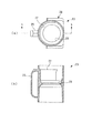
請求項16に係る発明は、請求項3に記載の飲料抽出装置において、抽出ユニットは、上方に開放する漏斗状のフィルタセット部を有するとともに、フィルタセット部にパーマネントフィルタを下方から支持した状態にセットする支持部材を有し、パーマネントフィルタは、プラスチックから成り、上下方向に貫通する多数の細孔を有する平板状のフィルタ本体部と、このフィルタ本体部の下面に突設され、フィルタセット部に載置されることにより、フィルタ本体部を水平に保持するフィルタ保持部と、を有していることを特徴とする。 According to a sixteenth aspect of the present invention, in the beverage extraction device according to the third aspect, the extraction unit has a funnel-shaped filter set portion that opens upward, and the permanent filter is supported on the filter set portion from below. The permanent filter has a supporting member to be set, and the permanent filter is made of plastic and has a flat plate-like filter main body portion having a large number of fine holes penetrating in the vertical direction, and is protruded from the lower surface of the filter main body portion. And a filter holding portion that holds the filter main body portion horizontally by being placed thereon.
この構成によれば、抽出ユニットが、パーマネントフィルタを下方から支持する支持部材を有しており、この支持部材の漏斗状のフィルタセット部にパーマネントフィルタがセットされる。抽出容器内で抽出された飲料の搬出時には、その飲料がフィルタ本体の多数の細孔を通って、フィルタセット部側に流れ、支持部材の外部に搬出される。この場合、フィルタ本体部の下面に突設されたフィルタ保持部がフィルタセット部に載置されることにより、フィルタ本体部が水平に保持されるので、飲料を搬出するために、フィルタ本体部に比較的高い圧力が作用しても、フィルタ本体部が変形することはない。これにより、抽出容器からの飲料の円滑かつ安定した搬出を確保することができる。また、金属製に比べて安価なプラスチック製のパーマネントフィルタを採用することにより、飲料抽出装置の製造コストを低減することができる。さらに、プラスチックは一般に、金属に比べて熱伝導率が低いので、プラスチック製のパーマネントフィルタを採用することにより、抽出容器内で抽出される飲料の温度低下を抑制することができる。これにより、例えば、温かい飲料を抽出する場合でも、その抽出温度を高く維持したり、温度低下した飲料の温度を上昇させたりするためのヒータなどを設ける必要がなく、省エネを図ることができる。 According to this configuration, the extraction unit has the support member that supports the permanent filter from below, and the permanent filter is set in the funnel-shaped filter set portion of the support member. When the beverage extracted in the extraction container is carried out, the beverage flows through the numerous pores of the filter body to the filter set side and is carried out of the support member. In this case, since the filter main body is horizontally held by placing the filter holding portion protruding from the lower surface of the filter main body on the filter set portion, the filter main body Even when a relatively high pressure is applied, the filter main body is not deformed. Thereby, smooth and stable carry-out of the beverage from the extraction container can be ensured. Moreover, the manufacturing cost of a drink extraction apparatus can be reduced by employ | adopting the permanent filter made from a plastic cheaper compared with metal. Furthermore, since plastics generally have a lower thermal conductivity than metals, by adopting a plastic permanent filter, it is possible to suppress the temperature drop of the beverage extracted in the extraction container. Thereby, for example, even when a hot beverage is extracted, it is not necessary to provide a heater or the like for maintaining the extraction temperature high or increasing the temperature of the beverage whose temperature has been lowered, and energy saving can be achieved.
請求項17に係る発明は、請求項16に記載の飲料抽出装置において、フィルタ保持部は、平面形状が格子状に形成された複数のリブを有していることを特徴とする。 According to a seventeenth aspect of the present invention, in the beverage extraction device according to the sixteenth aspect, the filter holding portion has a plurality of ribs whose planar shape is formed in a lattice shape.
この構成によれば、比較的簡単な構成のフィルタ保持部によって、フィルタ本体部を安定して水平に保持することができる。 According to this configuration, the filter main body can be stably held horizontally by the filter holding portion having a relatively simple configuration.
請求項18に係る発明は、請求項3に記載の飲料抽出装置において、本体駆動ユニットは、抽出ユニットに係合することにより、抽出ユニットを本体駆動ユニットに取り付けられた状態にロックするロック部を、さらに有し、抽出ユニットは、抽出ユニットを本体駆動ユニットから取り外すために操作される取外しレバーを有し、取外しレバーは、ロック部によるロックが行われているときに、ロック部に押圧されることによって位置するロック位置と、ロック部によるロックが行われていないときに位置する非ロック位置とに移動自在に構成されていることを特徴とする。 According to an eighteenth aspect of the present invention, in the beverage extraction device according to the third aspect, the main body driving unit engages with the extraction unit to thereby lock the extraction unit in a state attached to the main body driving unit. The extraction unit further includes a removal lever that is operated to remove the extraction unit from the main body drive unit, and the removal lever is pressed by the lock portion when the lock portion is locked. Thus, it is configured to be movable between a lock position positioned by this position and a non-lock position positioned when the lock portion is not locked.
この構成によれば、本体駆動ユニットのロック部が抽出ユニットに係合することにより、この抽出ユニットは、本体駆動ユニットに取り付けられた状態にロックされる。また、抽出ユニットには、抽出ユニットを本体駆動ユニットから取り外すために操作される取外しレバーが設けられている。この取外しレバーは、ロック部によるロックが行われているとき、すなわち、抽出ユニットが本体駆動ユニットに適正に取り付けられているときには、ロック部に押圧されることによって、ロック位置に位置する。一方、ロック部によるロックが行われていないとき、すなわち、抽出ユニットが本体駆動ユニットから取り外されているとき、および抽出ユニットが本体駆動ユニットに適正に取り付けられていないときには、取外しレバーは、非ロック位置に位置する。したがって、抽出ユニットを本体駆動ユニットに取り付けた作業者は、取外しレバーの位置を視認することによって、抽出ユニットが本体駆動ユニットに適正に取り付けられているか否かを容易に判断することができる。例えば、抽出ユニットを本体駆動ユニットに取り付けた場合でも、取外しレバーの位置が非ロック位置に位置するときには、ロック部によるロックが適正に行われておらず、したがって、抽出ユニットが本体駆動ユニットに適正に取り付けられていないと判断することができる。 According to this configuration, when the lock portion of the main body drive unit is engaged with the extraction unit, the extraction unit is locked in a state of being attached to the main body drive unit. Further, the extraction unit is provided with a removal lever that is operated to remove the extraction unit from the main body drive unit. The detachment lever is positioned at the lock position by being pressed by the lock portion when the lock portion is locked, that is, when the extraction unit is properly attached to the main body drive unit. On the other hand, when the lock unit is not locked, that is, when the extraction unit is detached from the main body drive unit, and when the extraction unit is not properly attached to the main body drive unit, the removal lever is unlocked. Located in position. Therefore, the operator who attached the extraction unit to the main body drive unit can easily determine whether or not the extraction unit is properly attached to the main body drive unit by visually recognizing the position of the removal lever. For example, even when the extraction unit is attached to the main unit drive unit, if the position of the removal lever is in the unlocked position, the lock unit is not properly locked, and therefore the extraction unit is appropriate for the main unit drive unit. It can be determined that it is not attached to.
請求項19に係る発明は、請求項18に記載の飲料抽出装置において、抽出ユニットは、前面に開閉自在に設けられた前面カバーを、さらに有し、取外しレバーは、前面にインジケータ部を有するとともに、前面カバーの後方に、左右方向に延びる軸線を中心として回動自在に設けられ、ロック位置に位置するときにインジケータ部の下端が前面カバーの下端と同じ高さに位置し、非ロック位置に位置するときにインジケータ部の下端が前面カバーの下端よりも下方に位置するように構成されていることを特徴とする。 The invention according to claim 19 is the beverage extraction device according to claim 18, wherein the extraction unit further has a front cover provided on the front face so as to be freely opened and closed, and the removal lever has an indicator part on the front face. It is provided behind the front cover so as to be rotatable about an axis extending in the left-right direction, and the lower end of the indicator portion is positioned at the same height as the lower end of the front cover when positioned at the locked position, and is in the unlocked position. It is characterized in that the lower end of the indicator unit is positioned below the lower end of the front cover when positioned.
この構成によれば、抽出ユニットの前面に、前面カバーが開閉自在に設けられ、その前面カバーの後方には、前面にインジケータ部を有する取外しレバーが、左右方向に延びる軸線を中心として回動自在に設けられている。この取外しレバーがロック位置に位置するときには、インジケータ部の下端が前面カバーの下端と同じ高さに位置する一方、取外しレバーが非ロック位置に位置するときには、インジケータ部の下端が前面カバーの下端よりも下方に位置する。したがって、抽出ユニットの前方から、前面カバーの下端を基準として、インジケータ部の下端の位置を視認するだけで、抽出ユニットが本体駆動ユニットに適正に取り付けられているか否かを容易に判断することができる。 According to this configuration, the front cover is provided to be openable and closable on the front surface of the extraction unit, and at the rear of the front cover, the detachable lever having the indicator portion on the front surface is rotatable about an axis extending in the left-right direction. Is provided. When the removal lever is in the locked position, the lower end of the indicator unit is positioned at the same height as the lower end of the front cover, while when the removal lever is in the unlocked position, the lower end of the indicator unit is lower than the lower end of the front cover. Is also located below. Therefore, from the front of the extraction unit, it is possible to easily determine whether or not the extraction unit is properly attached to the main body drive unit only by visually recognizing the position of the lower end of the indicator unit with reference to the lower end of the front cover. it can.
請求項20に係る発明は、請求項8に記載の飲料抽出装置において、各ロール部支持部材は、ロール部収容ケースの対応する側壁に貫通した状態に係合し、ロール部の端面の中央部に係合した状態で、ロール部を支持するためのロール部支持凸部と、このロール部支持凸部から側壁に沿って延び、側壁の外側に配置された脚部と、この脚部の両側において脚部の先端と異なる位置に設けられ、脚部の延び方向と直交しかつ側壁に沿って、互いに反対方向に突出する一対の支点軸部と、を有し、側壁は、一対の支点軸部にそれぞれ係合し、一対の支点軸部を抜止め状態に支持する一対の抜止め支持部を有していることを特徴とする。 According to a twentieth aspect of the present invention, in the beverage extraction device according to the eighth aspect of the present invention, each roll part support member engages with a corresponding side wall of the roll part housing case, and the center part of the end face of the roll part A roll part supporting convex part for supporting the roll part in a state of being engaged with the leg part, a leg part extending from the roll part supporting convex part along the side wall and disposed outside the side wall, and both sides of the leg part And a pair of fulcrum shafts that are provided at positions different from the tips of the leg portions and that are orthogonal to the extending direction of the leg portions and project in opposite directions along the side walls. It is characterized by having a pair of retaining support portions that respectively engage with each other and support the pair of fulcrum shaft portions in a retaining state.
この構成によれば、各ロール部支持部材では、ペーパーフィルタのロール部を支持するためのロール部支持凸部が、ロール部収容ケースの対応する側壁に貫通した状態に係合し、このロール部支持凸部から側壁に沿って延びる脚部が、側壁の外側に配置されている。また、この脚部の両側においてその先端と異なる位置に設けられた一対の支点軸部が、脚部の延び方向と直交しかつ側壁に沿って、互いに反対方向に突出している。そして、これらの支点軸部が、側壁に設けられた一対の支持部にそれぞれ係合し、抜止め状態に支持されている。 According to this structure, in each roll part support member, the roll part support convex part for supporting the roll part of a paper filter engages in the state which penetrated the corresponding side wall of the roll part accommodation case, and this roll part Leg portions extending along the side wall from the support convex portion are disposed outside the side wall. In addition, a pair of fulcrum shaft portions provided at positions different from the distal ends on both sides of the leg portion are orthogonal to the extending direction of the leg portion and protrude in opposite directions along the side wall. And these fulcrum shaft parts are respectively engaged with a pair of support parts provided in the side wall, and are supported in the retaining state.
ペーパーフィルタのロール部をロール部収容ケースにセットしたり、取り外したりする場合、各ロール部支持部材では、ロール部支持凸部がロール部で押圧されることによって、脚部が一対の支点軸部を支点として撓み、それにより、ロール部支持凸部が、対応する側壁側に退避する。そして、ロール部の中央部がロール支持凸部の位置に達したり、ロール部が取り外されたりすることにより、ロール部支持凸部への押圧が解除されることで、撓んでいた脚部が元に戻り、それにより、ロール部支持凸部も元の位置に戻る。このように、比較的簡単な構成のロール部支持部材を有するペーパーホルダユニットにおいて、ロール部収容ケースへのペーパーフィルタのロール部のセットおよび取外しを簡単に行うことができる。 When setting or removing the roll part of the paper filter in the roll part housing case, in each roll part support member, the leg part is a pair of fulcrum shaft parts by pressing the roll part support convex part with the roll part. As a fulcrum, whereby the roll support convex portion retracts to the corresponding side wall side. Then, when the central part of the roll part reaches the position of the roll support convex part or the roll part is removed, the pressure on the roll support convex part is released, so that the bent leg part is the original. Thus, the roll portion support convex portion also returns to the original position. As described above, in the paper holder unit having the roll part supporting member having a relatively simple configuration, the roll part of the paper filter can be easily set and removed from the roll part accommodation case.
請求項21に係る発明は、請求項20に記載の飲料抽出装置において、各抜止め支持部は、ロール部収容ケースの対応する側壁に突設され、側壁との間に各支点軸部を収容する凹部を有する係合部と、側壁の凹部の開口付近に設けられ、ロール部支持部材の側壁への取付けの際に凹部への支点軸部の圧入を許容し、支点軸部の凹部からの離脱を阻止する抜止め突起と、を有することを特徴とする。
The invention according to
この構成によれば、各ロール部支持部材をロール部収容ケースの対応する側壁に取り付ける場合、ロール部支持部材の各支点軸部を、対応する抜止め支持部の係合部に対し、その凹部の開口と抜止め突起との隙間から圧入する。そして、係合部の凹部に収容された支点軸部は、抜止め防止突起によって、凹部からの離脱が阻止される。このように、ロール部支持部材を、ロール部収容ケースの対応する側壁に、抜止め状態で直接取り付けることができる。 According to this structure, when attaching each roll part support member to the corresponding side wall of a roll part accommodation case, each fulcrum shaft part of a roll part support member is the recessed part with respect to the engaging part of a corresponding retaining support part. Press-fit from the gap between the opening and the retaining protrusion. And the fulcrum shaft part accommodated in the recessed part of the engaging part is prevented from detaching from the recessed part by the retaining prevention protrusion. Thus, the roll part support member can be directly attached to the corresponding side wall of the roll part accommodation case in a retaining state.
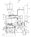
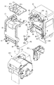
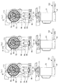
以下、図面を参照しながら、本発明の好ましい実施形態を詳細に説明する。図1および2は、ペーパーフィルタ式およびパーマネントフィルタ式のコーヒー抽出装置をそれぞれ備えたカップ式自動販売機の内部構造を模式的に示している。両図に示すように、これらのカップ式自動販売機1は、コーヒー抽出装置2(飲料抽出装置)により、コーヒー豆および湯(水)を用いてコーヒーを抽出し、購入者にカップ入りのレギュラーコーヒーを提供するものである。
Hereinafter, preferred embodiments of the present invention will be described in detail with reference to the drawings. 1 and 2 schematically show the internal structure of a cup type vending machine equipped with a paper filter type and a permanent filter type coffee brewing device, respectively. As shown in both figures, these cup-
ペーパーフィルタ式のコーヒー抽出装置2は、抽出されたコーヒーを、後述するペーパーフィルタPおよびメッシュフィルタ72でろ過するタイプのものであり、一方、パーマネントフィルタ式のコーヒー抽出装置2は、抽出されたコーヒーを、メッシュフィルタ72のみでろ過するタイプのものである。
The paper filter type
なお、以下の説明では、ペーパーフィルタ式およびパーマネントフィルタ式のコーヒー抽出装置2を区別する場合には、それぞれを適宜、「ペーパーブリュア2A」および「メッシュブリュア2B」と称呼するものとする。また、ペーパーブリュア2Aを備えたカップ式自動販売機1と、メッシュブリュア2Bを備えたカップ式自動販売機1とを区別する場合には適宜、前者に符号「1A」を、後者に符号「1B」を付すものとする。
In the following description, when the paper filter type and the permanent filter type
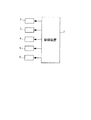
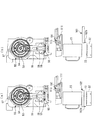
図1および図2に示すように、カップ式自動販売機1は、コーヒー抽出装置2と、このコーヒー抽出装置2に、所定量のコーヒー粉および湯をそれぞれ供給する原料供給装置3および給湯装置4と、コーヒー抽出装置2によって抽出されたコーヒーをクリームや砂糖とともに混合するミキシングボウル5と、このミキシングボウル5にクリームや砂糖を供給するクリーム・砂糖供給装置6とを備えている。また、これらは、図3に示すように、マイクロコンピュータを有する制御装置7によって制御される。
As shown in FIGS. 1 and 2, a cup
原料供給装置3は、コーヒー豆を収納する複数(図1および図2ではいずれも2つのみ図示)のキャニスタ11と、コーヒー豆を挽くミル12とを備えている。販売時に、キャニスタ11からシュート11aを介してミル12に供給されたコーヒー豆は、ミル12によって粉末状に挽かれ、そのコーヒー粉(以下「原料」という)が、シュート12aを介してコーヒー抽出装置2に供給される。給湯装置4は、湯を貯留する温水タンク13と、電磁弁で構成された湯弁14とを備えており、販売時やコーヒー抽出装置2のリンス時に、湯弁14が開放することにより、温水タンク13から所定量の湯が給湯チューブ15を介してコーヒー抽出装置2に供給される。ミキシングボウル5は、コーヒー抽出装置2によって抽出されたコーヒーを、クリーム・砂糖供給装置6からシュート6aを介して供給された所定量のクリームや砂糖とともに攪拌する。その後、ミキシングボウル5内のコーヒーは、ミキシングボウル5に接続された飲料チューブ16を介して、商品取出口10にセットされたカップCに供給される。
The raw
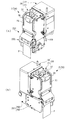
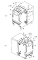
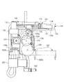
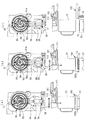
次に、コーヒー抽出装置2について詳述する。図4はペーパーブリュア2Aを、図5はメッシュブリュア2Bを示している。両図に示すように、ペーパーブリュア2Aおよびメッシュブリュア2Bは、コーヒーの抽出を実質的に行うブリュア本体20(抽出装置本体)がほぼ共通しており、前者2Aは、ブリュア本体20に後述するペーパーフィルタ送出し装置201を取り付けたものである一方、後者2Bは、ブリュア本体20のみで構成されたものである。
Next, the
図6は、ペーパーブリュア2Aを、後述するユニットごとに分解して示している。なお、以下の説明ではまず、両ブリュア2Aおよび2Bに共通のブリュア本体20について、両ブリュア2Aおよび2Bの相違点も含めて説明し、その後で、ペーパーブリュア2Aにおけるペーパーフィルタ送出し装置201について説明する。
FIG. 6 shows the
ブリュア本体20は、コーヒーを抽出するためのドリップユニット21(抽出ユニット)と、このドリップユニット21を駆動する本体駆動ユニット22で構成されている。本体駆動ユニット22は、自動販売機1内にねじ止めなどで固定されており、この本体駆動ユニット22に、ドリップユニット21が着脱自在に取り付けられている。
The
ドリップユニット21は、原料および湯が供給され、内部においてコーヒーの抽出を行うためのシリンダ23(抽出容器)と、このシリンダ23を着脱自在に収容するシリンダホルダ24とで構成されている。
The
図7は、シリンダ23がシリンダホルダ24から取り外された状態を示している。このシリンダ23は、プラスチックから成り、同図および図8に示すように、上下方向に延びるとともに上面および下面が開放し、所定のサイズ(例えば、高さ:102mm、容積:328ml)を有する円筒状に形成されている。また、シリンダ23の外周面には、シリンダ23をシリンダホルダ24に着脱する際に利用される取っ手25およびガイド部26が設けられている。ガイド部26は、互いに上下方向に所定間隔を隔てて設けられ、上下対称に形成された上下2つのガイド部26、26で構成されている。
FIG. 7 shows a state where the
また、シリンダ23の内面には、シリンダ23に供給された湯を内面の周方向に沿って案内するための湯案内壁27が設けられている。図8に示すように、湯案内壁27は、シリンダ23の上端付近と上下方向の中央部との間において、シリンダ23の内面に沿って設けられるとともに内方に若干突出し、平面形状が取っ手25の反対側に開放するU字状に形成されている。さらに、シリンダ23の内面には、その内面に沿って下方に流れた湯を、シリンダ23の下半部において周方向に拡散させるための湯拡散凸部28が設けられている。この湯拡散凸部28は、シリンダ23の上下方向の中央部において、内方に向かってテーパ状に所定長さ突出し、シリンダ23の周方向の全体にわたって延びている。
In addition, a hot
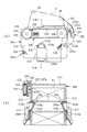
図9に示すように、シリンダホルダ24は、内側にシリンダ収容部24aを有するボックス状に形成されており、内側の下部に昇降自在に設けられ、シリンダ23内のコーヒーをろ過しながら外部に搬送するためのフィルタブロック32と、シリンダ収容部24aに収容されたシリンダ23を左右から挟んだ状態で保持するシリンダキャッチャ34と、上端部において回動自在に支持され、シリンダホルダ24の前面を開閉する前面カバー35などを備えている。
As shown in FIG. 9, the
また、シリンダホルダ24は、その外郭が、互いに所定間隔を隔てて対向する左右の側壁41、41と、両側壁41、41の後端部間にわたり、その上半部を覆うように設けられた背壁42と、両側壁41、41の下端部間わたるように設けられた底壁43などで構成されており、前面、上面および背面下半部が開放されている。なお、図示しないが、底壁43は、複数の棒状部材によって格子状に形成されている。また、左右の側壁41、41の上部には、前端寄りの位置に、両側壁41、41間を連結する前上カバー36が設けられ、この前上カバー36の後方に、シリンダホルダ24の上面を覆うホルダカバー37が着脱自在に取り付けられている。
Further, the
さらに、左右の側壁41、41の前端部および後端部にはそれぞれ、下部の所定位置に、ペーパーフィルタPを案内するためのガイドローラ38および39が着脱自在に取り付けられている。これらのガイドローラ38、39は、左右の側壁41、41間にわたって左右方向に延び、両側壁41、41に回転自在に支持されている。また、両ガイドローラ38、39は、ペーパーブリュア2Aのシリンダホルダ24には取り付けられる一方、メッシュブリュア2Bでは、取り外される(図5参照)。
Further, guide
シリンダホルダ24の左右の側壁41、41の各々は、側面形状がほぼ矩形状に形成されるとともに、外側の側面が開放したケース状の側壁本体44と、その開放した側面を覆うように、側壁本体44にねじ止めされた外カバー45とを備えている。そして、図10に示すように、各側壁41内には、フィルタブロック32および後述するシリンダヘッド101を駆動することによって、シリンダ23の下面および上面をそれぞれ開閉するシリンダ開閉機構51が設けられている。なお、左右のシリンダ開閉機構51、51は、左右の側壁41、41内に、ほぼ左右対称に構成されているので、以下の説明では、右側壁41に内蔵されたものを中心に説明する。
Each of the left and
図10および図11に示すように、シリンダ開閉機構51は、側壁本体44内の上半部の中央付近に突設された支軸44aに回転自在に支持され、所定形状の第1および第2カム溝53および54を有するカム円板55と、側壁本体44内の下半部に上下方向にスライド自在に設けられ、カム円板55の第1カム溝53に係合するとともにフィルタブロック32に連結されたスライダ56と、側壁本体44内の上部の所定位置に突設された支軸44bに回転自在に支持され、カム円板55の第2カム溝54に係合するとともに、後述するシリンダヘッド101をシリンダ23の上面に押圧した状態でロックするためのシリンダヘッドロック部材57とを備えている。
As shown in FIGS. 10 and 11, the cylinder opening /
カム円板55は、所定の直径および厚さを有する円板状に形成されており、周面全体にギヤ部55aが形成されている。また、カム円板55の外カバー45側の周縁部には、ほぼ1/2円弧分、径方向に若干突出した凸部55bが設けられている。さらに、カム円板55の側壁本体44側の側面に、前記第1および第2カム溝53、54が設けられている。
The
図12に示すように、第1カム溝53は、カム円板55の側面の周縁部に設けられ、カム円板55の支軸44aを中心とする円弧状にかつ反時計方向にほぼ一周するように延びる外側カム部61と、この外側カム部61に連なり、支軸44aに向かって円弧状に延びる駆動カム部62と、この駆動カム部62に連なり、支軸44aを中心とする円弧状にかつ支軸44aの付近でほぼ一周するように延びる内側カム部63とで構成されている。また、外側カム部61のうち、駆動カム部62付近の所定角度部分(以下「近接部61a」という)は、それ以外の外側カム部61に比べて、支軸44a寄りに形成されている。
As shown in FIG. 12, the
一方、第2カム溝54は、第1カム溝53の外側カム部61よりも内側に設けられ、支軸44aを中心とする円弧状にかつ外側カム部61の先端部付近から反時計方向にほぼ3/4円弧状に延びる外側カム部64と、この外側カム部64に連なり、支軸44aに向かって延びる駆動カム部65と、この駆動カム部65に連なり、支軸44aを中心とする円弧状に延びる内側カム部66とで構成されている。
On the other hand, the
スライダ56は、図11(b)に示すように、上下方向に延びるとともに下部が下方に向かって拡幅していて、ほぼ凸字状に形成されている。このスライダ56の上端部には、カム円板55側に突出する係合凸部56aが設けられており、この係合凸部56aが、カム円板55の第1カム溝53に摺動自在に係合している。また、スライダ56の下端部には、スライダ56と前記フィルタブロック32とを連結する2本の連結シャフト71、71が固定されている。両連結シャフト71、71は、互いに前後方向(図11では左右方向)に間隔を隔てかつ左右方向(図11では図の表裏方向)に平行に延びている。各連結シャフト71は、側壁本体44の上下方向に延びる長孔44cを貫通し、一端部が上記スライダ56に固定される一方、他端部が左側のシリンダ開閉機構51のスライダ56に固定されている。したがって、フィルタブロック32は、両連結シャフト71、71を介して、左右のスライダ56、56に支持されている。また、スライダ56の中央部には、上下方向に延びる長孔56bが形成されており、この長孔56bに、側壁本体44内の下部の所定位置に突設された支軸44dが摺動自在に貫通している。
As shown in FIG. 11B, the
以上のように構成されたスライダ56は、カム円板55の回転に伴い、側壁本体44内の上下方向に延びる一対のガイドレール44e、44e間に案内されながら、上下方向にスライドする。これに伴い、フィルタブロック32が昇降し、シリンダ23の下面を開閉する。具体的には、図10(a)および図11に示すカム円板55が、両図の時計方向に回転し、スライダ56の係合凸部56aが、第1カム溝53の外側カム部61から内側カム部63に向かって、駆動カム部62を摺動することにより、スライダ56が上昇する。
The
そして、スライダ56の係合凸部56aが、内側カム部63に到達することにより、ペーパーブリュア2Aのドリップユニット21では、フィルタブロック32がシリンダ23の下面に、ペーパーフィルタPを介して密着した状態で、これをシールする(図34(b)参照)。一方、メッシュブリュア2Bのドリップユニット21では、フィルタブロック32がシリンダ23の下面に直接、密着した状態で、これをシールする(図38(b)、図42(c)参照)。そして、それらの状態から、カム円板55が、反時計方向に回転し、スライダ56が下降することにより、フィルタブロック32も下降し、それにより、シリンダ23の下面が開放される(図36(b)、図40(b)、図44(b)参照)。
Then, when the engagement
図9、10および13に示すように、フィルタブロック32は、コーヒーをろ過するための円形のメッシュフィルタ72(パーマネントフィルタ)と、このメッシュフィルタ72の周囲を囲むように設けられた幅広リング状のパッキン73と、これらを上面において支持するとともに、上下に連通した通路を有するブロック状の支持部材74などで構成されている。メッシュフィルタ72は、シリンダ23の内径よりも一回り小さい薄板状の金属板(例えばステンレス板)から成り、所定の径(例えば30μm)を有する多数の細孔が形成されている。このように構成されたフィルタブロック32は、前述したように、スライダ56の上下方向のスライドに伴って昇降し、シリンダ23の下面の閉鎖時には、パッキン73の上面がシリンダ23の下面周縁部に当接した状態で、これをシールする。この場合、ペーパーブリュア2Aでは、フィルタブロック32が、シリンダ23との間にペーパーフィルタを挟持する一方、メッシュブリュア2Bでは、フィルタブロック32がシリンダ23に直接、当接する。
As shown in FIGS. 9, 10 and 13, the
また、フィルタブロック32の支持部材74と、右側壁41の背面下端部に設けられたジョイントホース40(図10参照)との間には、フィルタブロックチューブ32aが接続されている。なお、ジョイントホース40は、ドリップユニット21が本体駆動ユニット22に取り付けられた状態において、本体駆動ユニット22側の後述するジョイントホース140に接続される。
In addition, a
また、図10(a)および図11に示すように、右側の側壁41の下端部には、上記ジョイントホース40に接続された廃液チューブ50が設けられるとともに、この廃液チューブ50を開閉する廃液チューブピンチ部材58が設けられている。廃液チューブ50は、ゴムなどの弾性材で構成されており、ジョイントホース40から前方に水平に延びる水平部50aを有し、この水平部50aから下方に延びている。また、廃液チューブピンチ部材58は、上下方向に延びる板状に形成されており、上端部には、スライダ56の長孔56bに摺動自在に係合する係合凸部58aが設けられる一方、下端部には、廃液チューブ50の水平部50aの下側に、これを横切るように突出しかつ台形状の断面を有する押圧部58bが設けられている。さらに、廃液チューブ50の水平部50aの上側には、廃液チューブピンチ部材58と協働して廃液チューブ50をピンチし、これを閉鎖するための押さえばね59が設けられている。この押さえばね59は、細長い板ばねで構成されており、廃液チューブ50の水平部50aに沿って延び、これに接するように配置されている。また、押さえばね59の両端部は、上方に折り曲げられ、側壁本体44内の廃液チューブピンチ部材58の前後(図11では左右)に設けられた2つの支持部44f、44fに支持されている。
As shown in FIGS. 10A and 11, a
上記のように構成された廃液チューブピンチ部材58は、カム円板55の回転に伴うスライダ56の昇降に連動して、昇降する。具体的には、図11に示す状態から、スライダ56が上昇すると、その長孔56bの下端部が廃液チューブピンチ部材58の係合凸部58aに当接する。そして、スライダ56がさらに上昇すると、廃液チューブピンチ部材58が、係合凸部58aを介して持ち上げられることにより、上昇する。それにより、廃液チューブピンチ部材58の押圧部58bが、廃液チューブ50の水平部50aを下方から押し潰し、それにより、廃液チューブ50が閉鎖される(図34(b)など参照)。なお、この状態から、スライダ56が下降することにより、廃液チューブピンチ部材58も下降し、元の位置に戻る。
The waste
また、図11(b)に示すように、シリンダヘッドロック部材57は、上下方向に延びる所定形状に形成され、その中心部が、側壁本体44内の支軸44bに回動自在に支持されている。シリンダヘッドロック部材57の下端部には、カム円板55側に突出した係合凸部57aが設けられており、この係合凸部57aが、カム円板55の前記第2カム溝54に摺動自在に係合している。また、シリンダヘッドロック部材57の上端部には、後方に突出するように延びる鉤状のロック部57bが設けられている。
Further, as shown in FIG. 11B, the cylinder
このように構成されたシリンダヘッドロック部材57は、カム円板55の回転に伴って回動し、上端部のロック部57bによって、後述するシリンダヘッド101をシリンダ23の上面に押圧しかつロックすることにより、シリンダ23の上面をシールする。具体的には、図11(b)および図12に示すカム円板55が、両図の時計方向に回転し、シリンダヘッドロック部材57の係合凸部57aが、第2カム溝54の外側カム部64から内側カム部66に向かって、駆動カム部65を摺動することにより、シリンダヘッドロック部材57が、支軸44bを中心として、図11(b)の時計方向に回動する。そして、シリンダヘッドロック部材57のロック部57bが、後述するシリンダヘッド101の上部のヘッドガイドロッド113に係合するとともに、これを下方に押し下げるようにロックする。それにより、シリンダヘッド101がシリンダ23の上面に密着した状態で、これをシールする(図35(b)など参照)。
The cylinder
以上のように構成されたシリンダ開閉機構51は、前述したように、左右の側壁41、41にそれぞれ内蔵されており、両シリンダ開閉機構51、51のカム円板55のギヤ部55a、55aが、対応する側壁本体44内の所定位置に回転自在に設けられたギヤ76、76に噛み合っている。図10に示すように、両ギヤ76、76は、左右方向に水平に延びる動力伝達シャフト75の両端部に固定されており、各ギヤ76が対応する側壁本体44内の後端部の上下方向の中央部に配置されている。同図(b)に示すように、左側の側壁本体44に設けられたギヤ76(以下「従動ジョイントギヤ76A」という)は、後方に若干露出しており、ドリップユニット21が駆動ユニット22に取り付けられた状態において、駆動ユニット22側の後述する駆動ジョイントギヤ124に噛み合う。したがって、従動ジョイントギヤ76aが回転すると、これに噛み合う左側のカム円板55が回転し、動力伝達シャフト75および右側のギヤ76を介して、右側のカム円板55が左側のそれに同期して回転する。
As described above, the cylinder opening /
また、左右の側壁41、41にはそれぞれ、ドリップユニット21を本体駆動ユニット22から取り外す際に操作される取外しレバー84、84が設けられている。図11に示すように、取外しレバー84は、前後方向に延び、その長さ方向のほぼ中央において、前記支軸44dに回動自在に支持されている。取外しレバー84の前端部(図11の左端部)の操作部84aは、側壁41の外部に臨むとともに、側壁41の前部に設けられかつ前方に開放した凹部41aの内側に位置している。また、取外しレバー84の後端部は、下方に所定長さ延びており、その下端部に、側方に突出する取外し凸部84bが設けられている。この取外し凸部84bは、図6などに示すように、側壁41の外カバー45の所定位置に形成された長孔45aを介して、外部に突出している。
The left and
ここで、図6、図14および図15を参照して、本体駆動ユニット22に対するドリップユニット21の着脱構造について説明する。図6および図14に示すように、ドリップユニット21の左右の側面(外カバー45)には、後端部の所定位置に上下2つの係合凸部45b、45bが設けられている。各係合凸部45bは、外方に若干突出し、側面形状が下方に開口するコ字状に形成されている。また、ドリップユニット21の左右の側壁41、41には、背面の上端部および下端部に、後方に開放し、計4つの支持孔41b(図10(b)参照)が形成されている。
Here, with reference to FIG. 6, FIG. 14, and FIG. 15, the attachment / detachment structure of the
一方、本体駆動ユニット22の前部の左右端部にはそれぞれ、ドリップユニット21の上下の係合凸部45b、45bに対応するように、前方に突出する上下2つの鉤状のロック部85、85が設けられている。図14(b)に示すように、これらのロック部85、85は、上下方向に延びかつ側面形状が前方に開口するコ字状の連結部材86の上下の前端部に、それぞれ取り付けられている。また、左右の連結部材86、86は、上端部において板ばね87で連結されるとともに、下方に付勢されている。さらに、本体駆動ユニット22の左右両端部には、ドリップユニット21の4つの支持孔41bにそれぞれ対応する位置に、前方に突出する計4つの支持突起88(図6参照)が設けられている。
On the other hand, on the left and right ends of the front portion of the main
以上のように構成されたドリップユニット21側および本体駆動ユニット22側の着脱構造により、図14(b)に示すように、ドリップユニット21を本体駆動ユニット22の前側に取り付けた状態では、後者22の各支持突起88が前者21の各支持孔41bに挿入されるとともに、後者22の各ロック部85が前者21の各係合凸部45bに係合する。これにより、ドリップユニット21は、本体駆動ユニット22の前側にしっかりと取り付けられる。一方、ドリップユニット21を本体駆動ユニット22から取り外す場合には、図15(b)に示すように、ドリップユニット21の前面カバー35を若干開放し、左右の取外しレバー84の操作部84aを同時に押し下げる。これにより、各取外しレバー84の取外し凸部84bが、本体駆動ユニット22側の下側のロック部85を、板ばね87の付勢力に抗して押し上げ、その結果、上下のロック部85、85が、ドリップユニット21の上下の係合凸部45b、45bから外れる。そして、その状態のまま、ドリップユニット21を前方に引き出すことにより、ドリップユニット21が本体駆動ユニット22から取り外される。
In the state where the
また、図10(b)に示すように、ドリップユニット21の左側壁41内には、ドリップユニット21を本体駆動ユニット22から取り外したときに、カム円板55を回転不能にするためのカムロック機構89が設けられている。このカムロック機構89は、所定形状に形成され、従動ジョイントギヤ76Aの下方において上下方向にスライド自在のロック部材89aと、このロック部材89aを上方に付勢するばね89bとで構成されている。ドリップユニット21が本体駆動ユニット22から取り外されたときには、ロック部材89aが、従動ジョイントギヤ76Aに下方から係合することで、そのギヤ76Aを回転不能にする。これにより、従動ジョイントギヤ76Aに噛み合うカム円板55も回転不能となる。一方、ドリップユニット21が本体駆動ユニット22に取り付けられたときには、本体駆動ユニット22の前側に突設されたロック解除凸部90(図6参照)が、上記ロック部材89aに係合し、これを下方に押し下げることで、ロック部材89aによる従動ジョイントギヤ76Aのロックを解除する。これにより、従動ジョイントギヤ76Aが回転可能となり、それにより、カム円板55も回転可能となる。
Further, as shown in FIG. 10B, a cam lock mechanism is provided in the
上記のように、ドリップユニット21が本体駆動ユニット22から取り外された状態において、カム円板55を回転不能にロックするのは、次の理由による。すなわち、カム円板55の回転角度の制御は、後述するように、本体駆動ユニット22に設けられ、カム円板55と同期して回転するスイッチギヤ125aを有するモードスイッチ125を利用して行われる。そのため、スイッチギヤ125aとカム円板55の回転角度の整合性を保つ必要があるからである。
As described above, in the state where the
次に、シリンダホルダ24内に収容されたシリンダ23を把持するシリンダキャッチャ34について説明する。図9に示すように、シリンダキャッチャ34は、平面形状が前方に開口するコ字状の支持部材91と、この支持部材91の左右の前端部にそれぞれ固定された左右の把持部材92、92で構成されている。支持部材91は、板ばねから成り、左右方向に所定長さ延びる基部91aと、この基部91aの左右端部においてそれぞれ直角に屈曲し、前方に所定長さ延びる左右2つのアーム部91b、91bとで構成されている。基部91aは、背壁42の内側面にねじ止めされている。そして、両アーム部91b、91bの前端部に、前記把持部材92、92が固定されている。両把持部材92、92は、互いに対向し、それらの対向面が凸状に形成されている。
Next, the
このように構成されたシリンダキャッチャ34により、シリンダホルダ24のシリンダ収容部24aに収容されたシリンダ23は、支持部材91のばね力により、左右の把持部材92、92によって左右からしっかりと挟持される。
With the
図4〜図6に示すように、シリンダホルダ24の上面を覆うホルダカバー37は、平面形状がほぼ矩形状に形成されており、原料をシリンダ23に投入するための原料投入口37a、シリンダ23に湯を供給するための湯供給口37b、およびコーヒーの調理時に発生する湯気を排出するための湯気排出口37cが設けられている。原料投入口37aには、ミル12のシュート12a(図1、2参照)が接続され、湯供給口37bには、給湯チューブ15(図1、2参照)が接続され、そして、湯気排出口37cには、湯気抜き用のホース(図示せず)が接続されている。
As shown in FIGS. 4 to 6, the
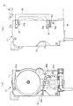
次に、図16〜図20を参照しながら、本体駆動ユニット22について説明する。本体駆動ユニット22は、上述したドリップユニット21のカム円板55、およびシリンダ23の上面を開閉するシリンダヘッド101を駆動するとともに、シリンダ23にエアを供給し、さらに、メッシュブリュア2Bでは、抽出滓を排出するためのスクレーパ102(抽出滓排出手段)を駆動するものである。
Next, the main
図16および図17はそれぞれ、ペーパーブリュア2Aおよびメッシュブリュア2Bの本体駆動ユニット22を示している。両図に示すように、本体駆動ユニット22は、その前壁を構成するプラスチック製のフレーム103(ケース)と、このフレーム103の上部から前方に突出し、前後方向に移動自在に設けられた前記シリンダヘッド101と、カム円板55を駆動するカム駆動機構104と、シリンダヘッド101およびスクレーパ102を駆動するシリンダヘッド・スクレーパ駆動機構105と、後述する複数のピンチ8を駆動するピンチ駆動機構106と、シリンダ23にエアを供給するエアポンプ107などを備えている。上記のカム駆動機構104、シリンダヘッド・スクレーパ駆動機構105、ピンチ駆動機構106、およびエアポンプ107は、フレーム103の背面側に取り付けられており、前面および底面が開放されたボックス状のユニットカバー108(ケース)によって覆われている。
16 and 17 show the main
シリンダヘッド101は、平面形状がシリンダ23の上面よりも大きい円形のヘッド本体111と、フレーム103の上部に設けられた上部開口103aを貫通した状態で、前後方向に移動自在に設けられ、前端部においてヘッド本体111を上下に若干揺動自在に支持するスライダ112とを有している。ヘッド本体111は、後述する第1エア搬送チューブ9Aに接続されており、ヘッド本体111の底面の所定位置には、第1エア搬送チューブ9Aを介して搬送されたエアを下方に送り出すためのエア供給口(図示せず)が設けられている。また、ヘッド本体111の上端部には、ヘッド本体111の外形よりも長く、左右方向に延びるヘッドガイドロッド113が設けられている。このヘッドガイドロッド113は、ドリップユニット21が本体駆動ユニット22に取り付けられた状態において、シリンダホルダ24の左右の側壁41、41の上端部に、前後方向に摺動自在に係合する。
The
さらに、ヘッド本体111の前半上部には、前記ホルダカバー37の原料投入口37aからの原料、および湯供給口37bからの湯を、シリンダ23に案内する原料・湯案内部材114が取り付けられている。この原料・湯案内部材114は、ヘッド本体111の前方に設けられた補助原料シュート115と、この補助原料シュート115の左方に設けられた湯案内受け部116とで一体に構成されている。補助原料シュート115は、上下方向に延びる筒状に形成されており、シリンダヘッド101が待機位置に位置するときに、ホルダカバー37の原料投入口37aとシリンダ23の間に位置し、原料投入口37aから投入された原料を、さらにシリンダ23に案内する。
Further, a raw material / hot
一方、湯案内受け部116は、上面が開放するケース状に形成されており、シリンダヘッド101が待機位置に位置するときに、ホルダカバー37の湯供給口37bから供給された湯を、さらにシリンダ23に案内するとともに、湯供給口37bから後だれする湯を受けることで、その湯でシリンダヘッド101が濡れるのを防止する。また、湯案内受け部116の底壁の前端部には、上下方向に貫通し、下方に若干突出する補助給湯ノズル116aが設けられている。この補助給湯ノズル116aは、シリンダヘッド101が待機位置に位置するときに、シリンダ23内の湯案内壁27に真上から臨む位置に配置されている。したがって、湯供給口37bから湯案内受け部116に流入し、補助給湯ノズル116aから吐出した湯は、シリンダ23内の湯案内壁27に上方から当たり、この湯案内壁27によって、シリンダ23の内面の周方向に案内されながら、シリンダ23内に流れ落ちる。また、シリンダ23の内面を伝って流れ落ちる湯は、シリンダ23内の湯拡散凸部28に一旦、受けられ、さらにシリンダ23の内面の周方向に拡がりながら、下方に流れる。以上のようにして、湯がシリンダ23に供給される。
On the other hand, the hot water
図16(a)に示すように、ペーパーブリュア2Aの本体駆動ユニット22では、フレーム103の中央部に設けられた中央部開口103bを前方から覆った状態で、上下方向に延びるペーパーガイドプレート109(ペーパーガイド部材)が取り付けられている。このペーパーガイドプレート109は、フレーム103の下半部を覆うとともに、側面形状が後方に凸湾曲する湾曲部109aと、この湾曲部109aから斜め下後方に所定長さ延びる傾斜部109bとを有している。
As shown in FIG. 16 (a), in the main
ペーパーフィルタPをドリップユニット21のシリンダ23とフィルタブロック32の間にセットする際に、ペーパーブリュア2Aの下方から、ペーパーフィルタPを手動で挿し入れながら送ることにより、ペーパーフィルタPの先端部が、ペーパーガイドプレート109の傾斜部109bに沿って上方に案内され、さらに湾曲部109aに沿って前方に案内される。これにより、ペーパーフィルタPは、ドリップユニット21の後ろ側から、シリンダ23とフィルタブロック32の間を通って、ドリップユニット21の前方に到達する。このように、ペーパーガイドプレート109を利用して、ペーパーフィルタPのセットを簡単に行うことができる。
When the paper filter P is set between the
また、図17(a)に示すように、メッシュブリュア2Bの本体駆動ユニット22では、フレーム103の中央部開口103bに、スクレーパ102がセットされる。同図(b)に示すように、スクレーパ102は、平面形状がフィルタブロック32のそれよりも一回り大きい矩形枠状に形成されたサポート102aと、サポート102aにその前端部から垂下するように取り付けられ、正面形状が横長矩形状のゴム製のスクレーパ本体102bとで構成されている。サポート102aの後端部には、左右方向に延びるとともに上方に開口した係合溝102cが設けられており、この係合溝102の所定位置に、後方に開口する切欠き102dが形成されている。
In addition, as shown in FIG. 17A, in the main
このように構成されたスクレーパ102は、フレーム103の中央部開口103の左右の縁部にガイドされながら、前後方向にスライド可能になっている。そして、このスクレーパ102が、シリンダヘッド・スクレーパ駆動機構105によって駆動されることにより、前端部のスクレーパ本体102bがフィルタブロック32上を前後方向に移動する。それにより、コーヒー抽出後にメッシュフィルタ72上に残留した原料である抽出滓は、スクレーパ本体102bで掻き取られ、ドリップユニット21の前方または後方に排出される。
The
図18に示すように、カム駆動機構104は、DCモータから成る第1モータ121(第1駆動源)と、この第1モータ121にギヤボックス122(図20参照)を介して接続された出力ギヤ123と、この出力ギヤ123に噛み合うとともに、ドリップユニット21が本体駆動ユニット22に取り付けられた状態において、ドリップユニット21側の前記従動ジョイントギヤ76Aに噛み合う駆動ジョイントギヤ124とを有している。
As shown in FIG. 18, the
出力ギヤ123の付近には、カム円板55の回転角度を制御するためのモードスイッチ125が設けられている。このモードスイッチ125は、中間ギヤ126を介して出力ギヤ123に噛み合うとともに、カム円板55と同期して、等角度で回転するスイッチギヤ125aを有している。モードスイッチ125は、スイッチギヤ125aが複数の所定の回転角度においてON状態になる複数のモードを有しており、前記制御装置7が、それらのモードに応じて、カム円板55の回転角度を識別する。
A
シリンダヘッド・スクレーパ駆動機構105は、DCモータから成る第2モータ131と、この第2モータ131に接続され、上下方向に延びかつ両端部が外部に突出する出力軸(図示せず)を有するギヤボックス132と、上記出力軸の上下端部にそれぞれ設けられたシリンダヘッド駆動部(図示せず)およびスクレーパ駆動部133(抽出滓排出手段)などで構成されている。シリンダヘッド駆動部は、シリンダヘッド101のスライダ112の後端部に係合しており、上記出力軸の回転に伴って回転することにより、シリンダヘッド101を、待機位置(図18の実線で示す位置)と、シリンダ23を閉鎖する閉鎖位置(図18の2点鎖線で示す位置)との間で、前後方向に駆動する。
The cylinder head /
一方、スクレーパ駆動部133は、水平に所定長さ延びるアーム133aと、その先端部から下方に突出する係合凸部133bとを有している。メッシュブリュア2Bの本体駆動ユニット22において、フレーム103の前方から中央部開口103bにスクレーパ102がセットされたときに、スクレーパ駆動部133の係合凸部133bが、スクレーパ102の後端部の切欠き102dを介して、係合溝102cに係合する。シリンダヘッド・スクレーパ駆動機構105の上記出力軸の回転に伴って、スクレーパ駆動部133が回転することにより、係合凸部133bがスクレーパ102の係合溝102c内を摺動する。これにより、スクレーパ102は、待機位置(図19の実線で示す位置)と、スクレーパ本体102bがフィルタブロック32の前端よりも前方の位置(図19の2点鎖線で示す位置)との間で、前後方向に移動する。
On the other hand, the
なお、上記のシリンダヘッド駆動部およびスクレーパ駆動部133はいずれも、ワンウェイクラッチを介して出力軸に連結されており、出力軸が所定方向に回転したときにシリンダヘッド駆動部のみが回転し、出力軸が上記と逆方向に回転したときにスクレーパ駆動部133のみが回転するようになっている。
The cylinder head drive unit and the
ピンチ駆動機構106は、コーヒー抽出時に、コーヒーやエアを搬送するための搬送チューブ9の複数の所定箇所を開閉するためのピンチ8を駆動するものである。ここで、図1、2を参照して、搬送チューブ9およびピンチ8配置関係について簡単に説明する。両図に示すように、搬送チューブ9は、エアポンプ107とシリンダヘッド101の間に接続された第1エア搬送チューブ9Aと、エアポンプ107と本体駆動ユニット22側のジョイントホース140の間に接続された第2エア搬送チューブ9Bと、ジョイントホース140に接続された飲料搬送チューブ9Cとで構成されている。これらの搬送チューブ9A〜9Cはいずれも、ゴムなどの弾性材で構成されている。上記ジョイントホース140は、本体駆動ユニット22の前側の右下端部に設けられており、ドリップユニット21が本体駆動ユニット22に取り付けられた状態において、ドリップユニット21側のジョイントホース40に接続される。
The
また、ピンチ8は、上記搬送チューブ9A〜9Cの途中にそれぞれ取り付けられた3つのピンチ、具体的には、第1エアピンチ8A、第2エアピンチ8Bおよび飲料ピンチ8Cで構成されている。これらのピンチ8A〜8Cは、同じものである。図20に示すように、各ピンチ8は、自身が取り付けられた搬送チューブ9の部分を保持するチューブホルダ141と、チューブホルダ141に回動自在に取り付けられ、これと協働して搬送チューブ9を押し潰し、閉鎖するためのピンチ本体142と、このピンチ本体142の搬送チューブ9と反対側に回転自在に設けられ、ピンチ本体142を搬送チューブ9側に押圧するための所定形状のカム143とで構成されている。
The
このように構成されたピンチ8A〜8Cは、第1および第2エアピンチ8A、8Bが、左右に隣接して配置され、飲料ピンチ8Cが、第1エアピンチ8Aの前方にこれに対向するように配置されている。なお、これらのピンチ8A〜8Cでは、カム143が共通化されている。
ピンチ駆動機構106は、前述したカム駆動機構104と共通の第1モータ121およびギヤボックス122と、その出力軸の右端部に固定された出力ギヤ144と、これに噛み合うとともに、ピンチ8のカム143の回転シャフト145に固定された駆動ギヤ146などを備えている。
The
上述したように、カム駆動機構104およびピンチ駆動機構106は、第1モータ121を共通の駆動源とし、前者104によるカム円板55、フィルタブロック32、シリンダヘッドロック部材57および廃液チューブピンチ部材58と、後者106による3つのピンチ8A〜8Cとを、相互に連係するように駆動する。これにより、コーヒーの抽出時において、シリンダ23の上面および下面の開閉、廃液チューブピンチ部材58による廃液チューブ50の開閉、ならびにピンチ8A〜8Cによる搬送チューブ9A〜9Cの開閉を、効率良くかつ適切に行うことができる。
As described above, the
次に、図21〜図28を参照して、ペーパーブリュア2Aのペーパーフィルタ送出し装置201について説明する。このペーパーフィルタ送出し装置201は、ペーパーフィルタPを保持するペーパーホルダユニット202と、このペーパーホルダユニット202を駆動するペーパー駆動ユニット203とで構成されている。ペーパーホルダユニット202は、ドリップユニット21の底面に、前後方向にスライドしながら着脱自在に取り付けられる一方、ペーパー駆動ユニット203は、本体駆動ユニット22の底面左端部に、前後方向にスライドしながら着脱自在に取り付けられている。
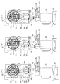
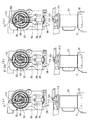
Next, the paper
図22、23および24に示すように、ペーパーホルダユニット202は、ドリップユニット21のシリンダ23の外径よりも幅広の帯状の連続するペーパーフィルタPと、このペーパーフィルタPを送出し可能に保持するホルダ本体204(ホルダ部)と、ホルダ本体204の前側上部に設けられた左右2つのペーパー送りドラム205、205(ペーパー送りローラ)と、ホルダ本体204の前端部に、両ペーパー送りドラム205、205を覆うように取り付けられたペーパーセットドア206(ペーパー挟持ローラ支持部材)と、ホルダ本体204の背面側に設けられたペーパー切れ検出レバー207と、ホルダ本体204の左側壁に内蔵され、ペーパー送りドラム205、205を回転駆動するためのドラム駆動機構208(送出し機構)などを備えている。
As shown in FIGS. 22, 23 and 24, the
ペーパーフィルタPは、コーヒー抽出用の一般的なものと同様、植物繊維などをきめ細かく織って作製されており、前述したメッシュフィルタ72よりもろ過度合が高くなっている。また、ペーパーフィルタPは、所定の内径を有する円筒状の芯部Psの周囲にロール状に巻かれたロール部Prを有している。
The paper filter P is produced by finely weaving plant fibers and the like, similar to a general one for coffee extraction, and has a higher degree of filtration than the
ホルダ本体204は、下面および前面下半部が開放するボックス状に形成され、内部にペーパーフィルタPのロール部Prを収容するプラスチック製のフレーム211(ロール部収容ケース)を備えている。フレーム211は、その中央部が、図23(b)に示すように、背面側から前面側にわたり、上方に凸の円弧状に形成されており、その天井部において取り付けられ、前面下端部まで延びるフィルムカバー212によって、前面下半部が覆われている。また、フレーム211は、左右の側壁213、213を有しており、左側の側壁213の外側にカバー215が取り付けられている。両側壁213、213にはいずれも、ほぼ中央の左右対称な位置に、所定の径を有する円形の開口213aが形成されている。そして、各側壁213の外側には、開口213aを介して、フレーム211の内部に対して出没自在に構成され、ペーパーフィルタPのロール部Prを支持するロール部支持部材216が取り付けられている。
The holder
ロール部支持部材216は、プラスチックの成形品で構成され、図24に示すように、側面形状が上記開口213aよりも一回り小さい円形の凸部216aと、この凸部216aから下方に延び、可撓性を有する所定形状の脚部216bとで構成されている。凸部216aは、側壁213の開口213aからフレーム211の内方に若干突出するように配置され、凸部216aの下半部に、下方に向かって側壁213に接近するように傾斜する傾斜面216cが形成されている。以上のように構成された左右のロール部支持部材216により、ペーパーフィルタPのロール部Prは、その芯部Psに凸部216aが挿入された状態で、回転自在に支持されている。
The
また、ペーパーホルダユニット202へのペーパーフィルタPの取付けおよび取外しは、次のように簡単に行える。すなわち、ペーパーフィルタPのロール部Prを、ホルダ本体204の下方からその内部に挿し入れると、ロール部Prの左右の端面が左右のロール部支持部材216の凸部216aの傾斜面216cに当接しながら、各凸部216aを側壁213側に押圧し、それにより、内方に突出していた各凸部216aが側壁213側に退避する。つまり、両凸部216a、216aは、左右に押し広げられる(図24(b)の2点鎖線で示す状態)。そして、ロール部Prの芯部Psが凸部216aの位置に達したときに、両凸部216aが内方に戻り、芯部Psに係合する。このように、ペーパーフィルタPの取付けは、ロール部Prをホルダ本体204に下方から挿し入れるだけで、簡単に行うことができる。
Moreover, attachment and removal of the paper filter P to the
一方、ペーパーフィルタPの交換時など、ペーパーホルダユニット202からペーパーフィルタPのロール部Prを取り外す場合には、そのロール部Prを、ホルダ本体204内で一旦押し上げる。この場合、ロール部Prの芯部Psの下半部の縁部が、左右のロール部支持部材216の傾斜面216cに当接し、それにより、上述したペーパーフィルタPの取付け時と同様、左右のロール部支持部材216の凸部216a、216aが左右に押し広げられる。そして、この状態から、ロール部Prを斜め下前方に引き出す。これにより、ロール部Prは、ホルダ本体204の前面下半部を介して、前方に取り出される。以上のように、ペーパーフィルタPの取外しも、上述した手順により、簡単に行うことができる。
On the other hand, when removing the roll part Pr of the paper filter P from the
なお、各ロール部支持部材216は、その脚部216bにおいて、所定の抜止め部材217により、フレーム211の側壁213にしっかりと取り付けられている。したがって、上述したペーパーフィルタPの取付けおよび取外しの際に、凸部216aがロール部Prで押圧されても、ロール部支持部材216が、フレーム211の側壁213から外れることはない。
In addition, each roll
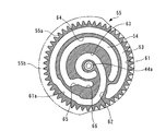
図22および図23に示すように、左右のペーパー送りドラム205、205は、形状およびサイズが互いに同じものであり、ホルダ本体204の左右の側壁213、213間にわたって左右方向に延び、かつ両側壁213、213に回転自在に支持されたドラムシャフト218に、互いに左右方向に間隔を隔てて固定されている。このペーパー送りドラム205は、所定の厚さおよび径を有する円弧部205aと、この円弧部205aの両端に直線的に連なる直線部205b(非挟持部)と、この直線部205bの内側縁部に突設され、円弧部205aの径よりも小さい径を有する小円弧部205cとにより、所定形状に形成されている。円弧部205aには、その周方向に沿って、多数の歯が形成されている。
As shown in FIGS. 22 and 23, the left and right paper feed drums 205, 205 have the same shape and size, extend in the left-right direction between the left and
ペーパーセットドア206は、左右方向に延びるドア本体221と、このドア本体221の両端部から直角に延び、側面形状が「く」字状の左右のアーム222、222とを備えている。ドア本体221の背面には、左右方向に延びるローラシャフト223が固定され、その両端部に、両ペーパー送りドラム205、205にそれぞれ対応するように、ローラ224、224(ペーパー挟持ローラ)が回転自在に支持されている。また、ドア本体221の前面には、ペーパーフィルタPで抽出滓を排出する際に、その抽出滓をペーパーフィルタPから分離するための滓分離プレート225(抽出滓分離部)が取り付けられている。この滓分離プレート225は、ペーパーホルダユニット202が前記ドリップユニット21に取り付けられた状態において、ドア本体221からドリップユニット21の前側のガイドローラ38付近まで、後ろ上がりに傾斜するように延びている。
The paper set
左右のアーム222、222は、その先端部の外面に突設された係合凸部222aが、ホルダ本体204の左右の側壁213の前端部に形成された縦長の係合孔213bに、内側から挿入された状態で、回動自在に支持されている。また、各アーム222の長さ方向のほぼ中央部と、対応する側壁213との間には、ペーパーセットドア206をホルダ本体204側に付勢するばね226が取り付けられている。さらに、各アーム222のドア本体221寄りの所定位置には、外方に突出し、対応する側壁213の前端上部に設けられた係止部213cに係止されることによって、ペーパーセットドア206を閉鎖した状態にロックするためのロック部222bが設けられている。
The left and
ペーパーフィルタPは、ホルダ本体204の背面下端部のガイドローラ204a、およびドリップユニット21の後ろ側のガイドローラ39で案内され、シリンダ23とフィルタブロック32の間を通り、さらにドリップユニット21の前側のガイドローラ38で案内され、ドリップユニット21の前側において垂下するようにセットされる。そして、ペーパーフィルタPの垂下した部分が、上記のように構成された左右のペーパー送りドラム205、205、およびペーパーセットドア206の両ローラ224、224によって挟持される。ペーパー送りドラム205、205が、ドラム駆動機構208によって、所定方向(図23(b)における時計方向)に回転駆動されることにより、上記のようにセットされたペーパーフィルタPが、ホルダ本体204内のロール部Pr側から送られる。
The paper filter P is guided by the
また、図22(b)および図23(b)に示すように、両ペーパー送りドラム205、205は、ペーパーフィルタPの送出し以外の待機時に、各直線部205bが対応するローラ224、224に対向するようになっている。この場合、ペーパーフィルタPは、ペーパー送りドラム205とローラ224とで挟持されない。したがって、ペーパーブリュア2Aのメンテナンスなどの際に、ペーパーフィルタPを、ペーパー送りドラム205およびローラ224の下方に、手動で簡単に引き出すことができる。また、コーヒーの抽出時におけるフィルタブロック32の上昇に伴い、ペーパーフィルタPがフィルタブロック32側に引っ張られた場合でも、ペーパーフィルタPがペーパー送りドラム205およびローラ224で挟持されていないので、ペーパーフィルタPが破れるなどの不具合を回避することができる。
Also, as shown in FIGS. 22B and 23B, the paper feed drums 205 and 205 are respectively in contact with the
また、ペーパーフィルタPを、ペーパー送りドラム205とローラ224の間にセットする場合、図23(b)に示すように、ペーパーセットドア206を前側に回動させることで開放することにより(離隔位置)、ペーパー送りドラム205とローラ224の間に比較的大きなスペースを確保することができる。そして、そのスペースにペーパーフィルタPを通した後で、ペーパーセットドア206を元の状態に閉鎖する(押圧位置)。このように、ペーパーセットドア206を開閉することにより、ペーパーフィルタPの上記セットを簡単に行うことができる。
When the paper filter P is set between the
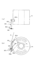
図23(b)および図25に示すように、ペーパー切れ検出レバー207は、ホルダ本体204のフレーム211の背面下端部に、左右方向に水平に延びる支軸207aを中心に回動自在に支持されている。また、ペーパー切れ検出レバー207は、支軸207aの右端部(図25(a)の上端部)から上方に延びる長尺のレバー本体207bと、支軸207aの左端部(図25(a)の下端部)から斜め下後方に若干延びる検出レバー部207cとを有している。前者207bは、フレーム211の内側に位置し、後者207cは、フレーム211の後方に突出している。また、ペーパー切れ検出レバー207の支軸207aの左端部には、ねじりばね228が取り付けられており、このねじりばね228により、ペーパー切れ検出レバー207が、図23(b)において、時計方向に付勢されている。したがって、同図に示すように、ペーパー切れ検出レバー207では、レバー本体207bがペーパーフィルタPのロール部Prの外周面に当接しており、図25(b)に示すように、ロール部Prの径の縮小に伴い、それに追従しながら、ペーパー切れ検出レバー207が時計方向に回動する。これに伴い、検出レバー部207cは、上方に回動し、そのことが、ペーパー駆動ユニット203側の後述するペーパー切れ検出スイッチ247によって検出される。
As shown in FIGS. 23B and 25, the paper
次に、左右のペーパー送りドラム205、205を回転駆動するドラム駆動機構208について説明する。図24に示すように、ドラム駆動機構208は、ホルダ本体204の左側壁、すなわちフレーム211の左側壁213とカバー215とで囲まれたスペースに設けられている。このドラム駆動機構208は、ドラムシャフト218の左側壁213から突出する端部に固定された前プーリ231と、左側壁213の後端部に回転自在に設けられた後プーリ232と、両プーリ231、232に巻き掛けられたタイミングベルト233と、後プーリ232と共通の支軸234に固定され、後プーリ232と左側壁213との間に配置された従動ギヤ235とを備えている。ペーパー駆動ユニット203の後述する駆動ギヤ244によって、従動ギヤ235が所定方向(図24(a)の時計方向)に回転駆動されることにより、後プーリ232が同じ方向に回転し、したがって、タイミングベルト233を介して、前プーリ231も同じ方向に回転する。それにより、左右のペーパー送りドラム205、205が前述したように回転し、ペーパーフィルタPを送る。
Next, the
また、フレーム211の上記従動ギヤ235の付近には、ペーパーホルダユニット202が、ドリップユニット21から取り外され、ペーパー駆動ユニット203と分離したときに、従動ギヤ235をロックするギヤロック機構236(ペーパー送りローラロック機構)が設けられている。図26に示すように、このギヤロック機構236は、所定形状のロック部材237と、このロック部材237を後方(図26の左方)に付勢するばね238で構成されている。ロック部材237は、横長リング状に形成され、従動ギヤ235の側面に一体に設けられたボス部235aの周囲を囲むリング部237aと、このリング部237aから前方に延び、フレーム211の左側壁213に前後方向にスライド自在に支持されたスライド部237bとを有している。また、リング部237aの内側の前端部には、後方に突出するロック凸部239が設けられている。
Further, in the vicinity of the driven
一方、従動ギヤ235のボス部235aの周面の所定位置には、外方に開口する係合凹部235bが形成されている。この係合凹部235bは、従動ギヤ235が待機位置に位置するときに、図26に示すように、ロック部材237のロック部239に対向する。
On the other hand, an
上記のように構成されたギヤロック機構236では、図26(a)に示すように、ペーパーホルダユニット202およびペーパー駆動ユニット203が、互いに離れた状態であるときに、ロック部材237がばね238で付勢され、ロック凸部239が従動ギヤ235の係合凹部235bに嵌合する。これにより、従動ギヤ235がロックされる。一方、ペーパーホルダユニット202およびペーパー駆動ユニット203が、互いに連結された状態では、ペーパー駆動ユニット203の前端部のロック部材当接部241aが、ロック部材237のリング部237aに後方から当接し、ばね238の付勢力に抗して、ロック部材237を前方に押圧する。これにより、ロック部材237のロック部239が、従動ギヤ235の係合凹部235bから外れ、その結果、従動ギヤ235が回転可能な状態となる。
In the
このように、ペーパーホルダユニット202が、ペーパー駆動ユニット203から取り外されたときに、従動ギヤ235がロックされるので、これと一体の後プーリ232に加えて、これとタイミングベルト233を介して連結された前プーリ231もロックされる。その結果、前プーリ231と共通の回転軸であるドラムシャフト218に固定された両ペーパー送りドラム205、205もロックされる。これにより、ペーパーホルダユニット202がペーパー駆動ユニット203から取り外された状態において、各ペーパー送りドラム205の直線部205bが、対応するローラ224に対向するように、ペーパー送りドラム205をロックすることができる。
Thus, when the
前述したように、待機時に、直線部205bがローラ224に対向するように、ペーパー送りドラム205が停止していることが好ましい。したがって、メンテナンスなどの際に、ペーパーホルダユニット202がペーパー駆動ユニット203から取り外され、再度、ペーパー駆動ユニット203に取り付けられるまで、ペーパー送りドラム205の停止角度位置を保つことができるので、待機時におけるペーパー送りドラム205の上記停止角度位置を確保することができる。また、ペーパー送りドラム205のロックの解除は、ペーパーホルダユニット202をペーパー駆動ユニット203に取り付けるだけで、簡単に行うことができる。
As described above, it is preferable that the
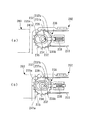
図27は、ペーパー駆動ユニット203を示しており、また図28は、ペーパー駆動ユニット203の内部構造を、ペーパーホルダユニット202とともに示している。両図に示すように、ペーパー駆動ユニット203は、その外郭を構成するケース241内の後部に配置されたモータ242(第2駆動源)と、このモータ242に接続され、ケース241の右側面に取り付けられたギヤボックス243と、ケース241内の前部に配置され、ギヤボックス243の左右方向(図28の表裏方向)に延びる出力軸243aに固定された駆動ギヤ244とを備えている。駆動ギヤ244の左側面には、所定位置に係合凹部245aを有するカム245が設けられている。また、駆動ギヤ244の後方に、カム245によってON/OFF切り替えされるマイクロスイッチから成るペーパー送り検出スイッチ246が配置されている。このペーパー送り検出スイッチ246は、その操作レバー246aの先端部にスイッチローラ246bを有しており、このスイッチローラ246bが駆動ギヤ244のカム245の周面に押圧されることにより、ON状態となり、スイッチローラ246bがカム245の係合凹部245aに対向し、押圧が解除されることにより、OFF状態となる。
FIG. 27 shows the
また、ペーパー駆動ユニット203には、ケース241の下端部に、マイクロスイッチから成るペーパー切れ検出スイッチ247(スイッチ)が設けられ、その下側に、これをON/OFF切り替えする切替えレバー248が配置されている。ペーパー切れ検出スイッチ247は、その操作レバー247aの先端部にスイッチローラ247bを有しており、このスイッチローラ247bが切替えレバー248によって下方から押圧されることにより、ON状態となり、その押圧が解除されることにより、OFF状態となる。
Further, the
図28(a)に示すように、切替えレバー248は、前後方向に延び、後端部(同図の左端部)の支点248aを中心として、ペーパー切れ検出スイッチ247をON状態に切り替えるON切替え位置(図28(a)に示す位置)と、OFF状態に切り替えるOFF切替え位置(図28(b)に示す位置)との間で、ケース241に回動自在に支持されている。また、切替えレバー248の前端部には、斜め上および斜め下に延びる二股状の係合部248bが設けられている。さらに、切替えレバー248の支点248aには、ねじりばね249(付勢手段)が設けられ、このねじりばね249により、切替えレバー248が、図28において反時計方向に付勢されている。
As shown in FIG. 28 (a), the switching
したがって、図28(a)に示すように、ペーパーホルダユニット202とペーパー駆動ユニット203が分離した状態では、ペーパー切れ検出スイッチ247が、切替えレバー248に下方から押圧され、ON状態となる。一方、同図(b)に示すように、ペーパーホルダユニット202がペーパー駆動ユニット203に取り付けられた状態では、ペーパーホルダユニット202側のペーパー切れ検出レバー207の検出レバー部207cが、ペーパー駆動ユニット203側の切替えレバー248の前端部の係合部248bに係合する。
Therefore, as shown in FIG. 28A, in a state where the
図23(b)に示すように、ペーパーフィルタPの残量が十分ある場合には、ペーパー切れ検出レバー207の下端部の検出レバー部207cは、後方斜め下に延びるように位置する。この場合、図28(b)に示すように、検出レバー部207cは、ペーパー駆動ユニット203の切替えレバー248の係合部248bに係合し、これを下方に押圧する。これにより、切替えレバー248は、OFF切替え位置に位置し、その結果、ペーパー切れ検出スイッチ247がOFF状態であることで、前記制御装置7により、ペーパー切れでないと判別される。
As shown in FIG. 23B, when the remaining amount of the paper filter P is sufficient, the
一方、コーヒーの抽出によるペーパーフィルタPの使用に伴い、ペーパーフィルタPのロール部Prの径が、図25(b)の2点鎖線で示すように小さくなり、所定の径に達すると、ペーパー切れ検出レバー207の下端部の検出レバー部207cが、ほぼ水平に延びるように位置する。これより、検出レバー部207によるペーパー駆動ユニット203側の切替えレバー248の押圧が解除される。それにより、切替えレバー248は、ねじりばね249の付勢力により、ON切替え位置に位置し、その結果、ペーパー切れ検出スイッチ247がON状態であることで、制御装置7により、ペーパー切れであると判別される。
On the other hand, with the use of the paper filter P by coffee extraction, the diameter of the roll part Pr of the paper filter P becomes smaller as shown by the two-dot chain line in FIG. The
また、上記のペーパー切れ検出レバー207は、ペーパー切れに加えて、ペーパーホルダユニット202がペーパー駆動ユニット203に適正に取り付けられているか否かの判別にも利用される。すなわち、ペーパーホルダユニット202がペーパー駆動ユニット203から取り外されたときには、図28(a)に示すように、ペーパー駆動ユニット203の切替えレバー248がON切替え位置に位置し、ペーパー切れ検出スイッチ247がON状態となる。この状態から、ペーパーホルダユニット202がペーパー駆動ユニット203に適正に取り付けられたときには、図28(b)に示すように、ペーパー切れ検出レバー207の検出レバー部207cが、ペーパー駆動ユニット203側の切替えレバー248の係合部248bに係合し、これを下方に押圧する。これにより、切替えレバー248は、OFF切替え位置に位置し、その結果、ペーパー切れ検出スイッチ247がON状態からOFF状態になることで、制御装置7により、ペーパーホルダユニット202が適正に取り付けられたと判別される。
Further, the paper
一方、ペーパーホルダユニット202がペーパー駆動ユニット203に適正に取り付けられていないときには、ペーパー切れ検出レバー207の検出レバー部207cが、ペーパー駆動ユニット203側の切替えレバー248に適正に係合しないことで、切替えレバー248がON切替え位置に維持され、その結果、ペーパー切れ検出スイッチ247がON状態のままとなる。つまり、ペーパーホルダユニット202をペーパー駆動ユニット203に取り付けたときに、本来、ペーパ切れ検出スイッチ247がOFF状態になるはずであるのに、ペーパー切れ検出スイッチ247がON状態のままであることで、ペーパーホルダユニットが適正に取り付けられていないと判別することが可能である。以上のように、ペーパー切れ検出レバー207を利用して、ペーパーホルダユニット202がペーパー駆動ユニット203に適正に取り付けられているか否かを、容易に判別することができる。
On the other hand, when the
次に、以上のように構成されたコーヒー抽出装置2の動作について、図29〜図33のフローチャート、および図34〜図44の動作図を参照しながら説明する。なお、動作図では、上段にカム円板55の回転動作を中心に示し、下段にフィルタブロック32およびシリンダヘッド101の動作を中心に示すものとする。また、以下の説明ではまず、ペーパーブリュア2Aによるコーヒーの調理動作について、図34〜図37の動作図を参照して説明し、その後で、メッシュブリュア2Bによるコーヒーの調理動作について説明する。
Next, the operation of the
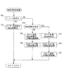
図29は、ペーパーブリュア2Aおよびメッシュブリュア2Bをそれぞれ備えたカップ式自動販売機1Aおよび1Bにおいて、購入者によるコーヒーの商品選択ボタンの操作に基づく販売指令があったときの販売動作の実行処理(メインルーチン)を示している。この制御プログラムは、カップ式自動販売機1Aおよび1Bのいずれにも対応しており、両ブリュア2Aおよび2Bに対し共通化されたものである。
FIG. 29 shows the execution processing of the sales operation when there is a sales instruction based on the operation of the product selection button of the coffee by the purchaser in the cup
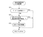
また、図34(a)は、ペーパーブリュア2Aの待機状態を示している。この待機状態では、カム円板55、フィルタブロック32およびシリンダヘッド101が、それぞれの待機位置に位置するとともに、シリンダ23の上面および下面がいずれも開放されている。なお、この待機状態では、図45の(1)に示すように、第1エアピンチ8A、第2エアピンチ8Bおよび飲料ピンチ8Cがいずれも開放状態であり、したがって、ピンチ8Aから8Cにそれぞれ対応する搬送チューブ9A〜9Cがいずれも開放されている。
FIG. 34 (a) shows the standby state of the
図29に示す販売動作のメインルーチンではまず、ステップ1(「S1」と図示。以下同じ)において、抽出滓排出用イニシャル処理(サブルーチン)を実行する。図30は、抽出滓排出用イニシャル処理を示している。同図に示すように、本サブルーチンではまず、ペーパーフィルタPが有るか否かを判別する(ステップ21)。具体的には、ブリュア本体20にペーパー駆動ユニット203が取り付けられ、このペーパー駆動ユニット203のモータ242が制御装置7に電気的に接続されているか否かによって判別される。ペーパーブリュア2Aは、ペーパー駆動ユニット203を備えているので、上記ステップ22の判別結果がYESとなり、そのまま本サブルーチンを終了する。
In the main routine of the selling operation shown in FIG. 29, first, in step 1 (illustrated as “S1”, the same applies hereinafter), the initial process (subroutine) for discharging the extracted soot is executed. FIG. 30 shows the initial process for discharging the extracted soot. As shown in the figure, in this subroutine, it is first determined whether or not the paper filter P is present (step 21). Specifically, the
図29のメインルーチンに戻り、ステップ2において、フィルタブロック32を上昇させる。具体的には、本体駆動ユニット22において、カム駆動機構104の第1モータ121が所定方向に回転することにより、ドリップユニット21のカム円板55が、図34において時計方向に回転する。それにより、カム円板55の第1カム溝53に係合するスライダ56が上昇し、これに支持されたフィルタブロック32が、その上側のペーパーフィルタPとともに上昇する。この場合、スライダ56の上昇途中において、スライダ56の長孔56bの下縁部が、廃液チューブピンチ部材58の係合凸部58aに当接し、その後、スライダ56の上昇に伴って、廃液チューブピンチ部材58も上昇する。そして、図34(b)に示すように、カム円板55が待機位置から約180度回転することにより、フィルタブロック32がシリンダ23の下面にペーパーフィルタPを押し当てた状態で、シリンダ23の下面をシールする。またこの場合、廃液チューブピンチ部材58が、その押圧部58bと押さえばね59との間で、廃液チューブ50を押し潰すことにより、これを閉鎖する。
Returning to the main routine of FIG. 29, in
次いで、この状態において、原料供給装置3および給湯装置4からそれぞれ、所定量の原料(例えば10g)および湯(例えば105ml)を、シリンダ23内に供給する(ステップ3)。具体的には、原料は、ホルダカバー37の原料投入口37aおよびシリンダヘッド101の補助原料シュート115を介して、シリンダ23に供給される。また、購入者によって、コーヒーの増量ボタンが操作され、後述する大容量抽出を実行する場合には、上記よりも多い原料(例えば15g)をシリンダ23に供給する。一方、湯は、ホルダカバー37の湯供給口37bおよびシリンダヘッド101の補助給湯ノズル116aを介して、シリンダ23に供給される。なお、この原料・湯の供給状態では、図45の(2)に示すように、第2エアピンチ8Bのみが開放状態となり、他のピンチ8Aおよび8Cがいずれも閉鎖状態になっている。
Next, in this state, a predetermined amount of raw material (for example, 10 g) and hot water (for example, 105 ml) are respectively supplied from the raw
また、原料および湯の供給後、上記の状態のまま、エアポンプ107を所定時間、作動させることにより、攪拌用エアをシリンダ23に供給する(ステップ4)。具体的には、エアポンプ107から、第2エア搬送チューブ9Bおよびフィルタブロックチューブ32aを介して、エアがフィルタブロック32に送られる。これにより、そのエアが、フィルタブロック32のメッシュフィルタ72およびペーパーフィルタPを通過し、シリンダ23内の原料および湯を攪拌する。
In addition, after supplying the raw material and hot water, the
上記攪拌の終了後、図34(c)に示すように、給湯装置4から、後湯として所定量の湯(例えば50ml)を、シリンダ23内に供給する(ステップ5)。このように後湯を供給することにより、原料供給時に原料がシリンダ23の内面上部に付着した場合でも、その原料を、後湯によってシリンダ23の内面から脱離させることができる。その結果、シリンダ23に供給されたすべての原料を、コーヒーの調理に有効に使用できるとともに、シリンダ23に付着していた原料が次回の販売時に使用されるのを防止することで、次回の販売に、良質のコーヒーを調理することができる。
After the completion of the stirring, as shown in FIG. 34 (c), a predetermined amount of hot water (for example, 50 ml) is supplied from the hot
次いで、本体駆動ユニット22において、シリンダヘッド・スクレーパ駆動機構105の第2モータ131が所定方向に回転することにより、シリンダヘッド駆動部が所定角度(例えば180度)、回転し、それにより、待機位置のシリンダヘッド101が前進する(ステップ6)。具体的には、図35(a)に示すように、シリンダヘッド101のヘッド本体111がシリンダ23の真上に到達する。そして、この状態のまま、エアポンプ107を所定時間、再度作動させることにより、上述した攪拌と同様、攪拌用エアをシリンダ23に供給する(ステップ7)。以上により、シリンダ23の内部において、コーヒーが抽出される。
Next, in the main
次いで、カム駆動機構104の第1モータ121が再度回転し、それにより、カム円板55がさらに回転する。そして、図35(b)に示すように、カム円板55が待機位置から約240度回転することにより、カム円板55の第2カム溝54に係合するシリンダヘッドロック部材57が、同図において時計方向に若干回動し、そのロック部57bによって、ヘッドガイドロッド113を下方に押し下げ、シリンダヘッド101をロックする(ステップ8)。これにより、シリンダヘッド101は、ヘッド本体111がシリンダ23の上面に当接した状態でこれをシールする。なお、この状態では、図45の(3)に示すように、第1エアピンチ8Aおよび飲料ピンチ8Cが開放状態となる一方、第2エアピンチ8Bが閉鎖状態となる。
Next, the
そして、ステップ9において、コーヒーの抽出処理(サブルーチン)を実行する。図31は、コーヒー抽出処理を示している。同図に示すように、本サブルーチンではまず、前述したステップ21と同様にして、ペーパーフィルタPが有るか否かを判別する(ステップ31)。ペーパーブリュア2Aでは、ステップ31の判別結果がYESとなり、続くステップ32において、大容量抽出か否かを判別する。この大容量抽出は、購入者によって、コーヒーの増量ボタンが操作されたときに実行されるコーヒーの抽出処理である。
In
コーヒーの増量ボタンが操作されていないとき(ステップ32:NO)には、ステップ33に進み、エアポンプ107を所定時間、作動させることにより、搬出用エアをシリンダ23に供給する。具体的には、エアポンプ107から、第1エア搬送チューブ9Aを介して、エアが、シリンダヘッド101に送られ、シリンダ23に供給される。そのエアにより、シリンダ23内が加圧され、内部で抽出されたコーヒーは、ペーパーフィルタPおよびメッシュフィルタ72でろ過され、フィルタブロック32、フィルタブロックチューブ32a、飲料搬送チューブ9C、ミキシングボウル5および飲料チューブ16を順に通って、商品取出口10にセットされたカップCに供給される。
When the coffee increase button is not operated (step 32: NO), the process proceeds to step 33, and the
一方、コーヒーの増量ボタンが操作されたとき(ステップ32:YES)には、ステップ34に進み、大容量抽出処理(サブルーチン)を実行する(ステップ34)。図32は、大容量抽出処理を示している。同図に示すように、本サブルーチンではまず、上述した図31のステップ33と同様にして、搬出用エア(1回目)をシリンダ23に供給する(ステップ41)。これにより、シリンダ23内で抽出されたコーヒーは、1回目の抽出によるコーヒーとして、カップCに供給される。ただしこの場合、シリンダ23内のコーヒーが完全に搬出される前に、エアポンプ107を停止し、すでにシリンダ23に供給されたエアの残圧によって、コーヒーの搬出を行うのが好ましい。これにより、原料の微粉末がコーヒーとともに搬出され、カップCに供給されるのを低減し、それにより、雑味の無い良質のコーヒーをカップCに供給することができる。
On the other hand, when the coffee increase button is operated (step 32: YES), the process proceeds to step 34 to execute a large-capacity extraction process (subroutine) (step 34). FIG. 32 shows the large capacity extraction process. As shown in the figure, in this subroutine, first, the carry-out air (first time) is supplied to the
次いで、カム駆動機構104の第1モータ121が上記と逆方向に回転することにより、カム円板55も逆方向に所定角度(約60度、待機位置から約180度)、回転する。この場合、図35(c)に示すように、シリンダヘッドロック部材57によるヘッドガイドロッド113のロックが解除されることで、シリンダヘッド101のロックを解除する(ステップ42)。なおこの場合、そのヘッドガイドロッド113は、カム円板55の凸部55bで押し上げられる。
Next, when the
次いで、シリンダヘッド・スクレーパ駆動機構105の第2モータ131が、上記と同じ方向に回転することにより、シリンダヘッド駆動部が、さらに所定角度(例えば180度)、回転し、それにより、図37(a)に示すように、シリンダヘッド101が後退し、待機位置に戻る(ステップ43)。これにより、シリンダ23の上面が開放される。そして、給湯装置4から、追加湯として所定量の湯(例えば140ml)を、シリンダ23内に供給する(ステップ44)。
Next, when the
また、追加湯の供給後、前記ステップ4と同様にして、攪拌用エアをシリンダ23に供給し(ステップ45)、シリンダ23内の既存の原料および追加湯を攪拌する。この攪拌の終了後、前記ステップ6および8と同様にして、待機位置のシリンダヘッド101をシリンダ23の真上まで前進させる(ステップ46)とともに、そのシリンダヘッド101をロックする(ステップ47)。これにより、図37(b)に示すように、シリンダ23の上面がシリンダヘッド101でシールされる。そして、図31のステップ33と同様にして、搬出用エア(2回目)をシリンダ23に供給する(ステップ48)。これにより、シリンダ23内で抽出されたコーヒーは、2回目の抽出によるコーヒーとして、カップCに供給される。
Further, after supplying the additional hot water, the air for stirring is supplied to the
なお、上述した大容量抽出が実行される場合、2回目の抽出によるコーヒーのカップCへの供給が完了するまで、商品取出口10の取出口扉10aは、図示しないロック機構によって、開放不能になっている。これにより、1回目の抽出によるコーヒーのカップCへの供給が完了した後に、購入者が誤って、カップCを商品取出口10から取り出すのを防止することができる。
When the above-described large-capacity extraction is performed, the
図29のメインルーチンに戻り、上述したステップ9のコーヒー抽出処理の終了後、図32の前記ステップ42と同様にして、シリンダヘッド101のロックを解除し(ステップ10)、その後、前記ステップ43と同様にして、シリンダヘッド101が後退し、待機位置に戻る(ステップ11)。
Returning to the main routine of FIG. 29, after completion of the coffee extraction process in
次いで、上記の状態のまま、図36(a)に示すように、給湯装置4から所定量の湯(例えば8ml)を、シリンダ23の内面を洗浄するためのリンス湯(1回目)として、シリンダ23に投入する(ステップ12)。前述したように、シリンダ23の内部の形状、および待機位置に位置するシリンダヘッド101の補助給湯ノズル116aの位置関係により、補助給湯ノズル116aを介してシリンダ23に投入されるリンス湯は、シリンダ23の内面を伝いかつ周方向に拡がりながら流れ落ちる。これにより、シリンダ23からのコーヒーの搬出後に、シリンダ23の内面に付着した抽出滓は、リンス湯とともに、下方に流れ落ちる。
Next, as shown in FIG. 36 (a), a predetermined amount of hot water (for example, 8 ml) is used as rinse water (first time) for cleaning the inner surface of the
その後、カム駆動機構104の第1モータ121が上記と同じ方向に回転することにより、カム円板55が所定角度(約180度)、回転し、それにより、図36(b)に示すように、フィルタブロック32が下降し(ステップ13)、待機位置に戻る。この場合、フィルタブロック32上のペーパーフィルタPには、抽出滓Gが残留する。そして、この状態のまま、同図に示すように、給湯装置4から所定量の湯(例えば10ml)を、リンス湯(2回目)として、さらにシリンダ23に投入する(ステップ14)。この2回目のリンス湯により、シリンダ23の下端部に付着・残留していた抽出滓が洗い流され、ペーパーフィルタP上に落下する。
Thereafter, the
そして、抽出滓排出処理(サブルーチン)を実行して(ステップ15)、図29のメインルーチンを終了し、待機状態に戻る。図33は、抽出滓排出処理を示している。同図に示すように、本サブルーチンではまず、前述したステップ21と同様にして、ペーパーフィルタPが有るか否かを判別する(ステップ51)。ペーパーブリュア2Aでは、このステップ51の判別結果がYESとなり、ペーパーフィルタPを所定長さ送り(ステップ52)、それにより、図36(c)に示すように、ペーパーフィルタP上の抽出滓Gを前方に排出する。この場合、同図に示すように抽出滓Gは、ペーパーホルダユニット202の滓分離プレート225によって、ペーパーフィルタPから分離される。そして、排出された抽出滓Gは、下方の滓バケツBに収容される。
Then, the extracted soot discharge process (subroutine) is executed (step 15), the main routine of FIG. 29 is terminated, and the process returns to the standby state. FIG. 33 shows the extracted soot discharging process. As shown in the figure, in this subroutine, first, similarly to step 21 described above, it is determined whether or not the paper filter P is present (step 51). In the
以上により、ペーパーブリュア2Aを備えたカップ式自動販売機1Aによるコーヒーの販売が終了する。
Thus, the sale of coffee by the cup
次に、メッシュブリュア2Bによるコーヒーの調理動作について、図38〜図44の動作図を参照しながら説明する。このメッシュブリュア2Bによるコーヒーの調理動作は、上述したペーパーブリュア2Aに対し、図29のメインルーチンのうち、ステップ1、10および15の3つのサブルーチンのみが異なっており、その他の制御については、上述したペーパーブリュア2Aと共通している。したがって、以下の説明では、これらのサブルーチンを中心として説明するものとする。
Next, the coffee cooking operation by the
また、メッシュブリュア2Bでは、抽出滓の排出方向があらかじめ、ドリップユニット21の前方または後方に排出するように設定でき、さらには、所定回数(例えば1〜10回)ごとに、前方および後方に交互に排出するように設定できるようになっている。したがって、以下の説明では、まず、図38〜図41の動作図を参照しながら、抽出滓の排出方向が前方に設定されているメッシュブリュア2B(以下、適宜「前排出メッシュブリュア2B」という)の動作について説明し、その後で、図42〜図44の動作図を参照しながら、抽出滓の排出方向が後方に設定されているメッシュブリュア2B(以下、適宜「後排出メッシュブリュア2B」という)の動作について説明する。
Further, in the
図38(a)は、前排出メッシュブリュア2Bの待機状態を示している。この待機状態では、上述したペーパーブリュア2Aと同様、カム円板55、フィルタブロック32およびシリンダヘッド101が、それぞれの待機位置に位置するのに加えて、スクレーパ102が、フィルタブロック32の後方の待機位置に位置している。
FIG. 38A shows a standby state of the front
前記図29に示すように、販売動作のメインルーチンではまず、ステップ1において、サブルーチンである抽出滓排出用イニシャル処理を実行し、本サブルーチンでは、前記図30に示すように、ペーパーフィルタPが有るか否かを判別する(ステップ21)。本例では、メッシュブリュア2Bが、ペーパー駆動ユニット203を備えていないので、上記ステップ21の判別結果がNOとなり、ステップ22に進み、スクレーパ102による抽出滓の排出方向が前方であるか否かを判別する。本例の前排出メッシュブリュア2Bでは、抽出滓の排出方向が前方に設定されているので、上記ステップ22の判別結果がYESとなり、そのまま本サブルーチンを終了する。
As shown in FIG. 29, in the main routine of the sales operation, first, the initial processing for discharging the extracted soot, which is a subroutine, is executed in
図29のメインルーチンに戻り、前記ステップ2〜8を実行する。図38(b)、(c)および図39(a)、(b)はそれぞれ、前述したペーパーブリュア2Aの動作図である図34(b)、(c)および図35(a)、(b)に対応するものである。
Returning to the main routine of FIG. 29,
次いで、ステップ9において、サブルーチンであるコーヒー抽出処理を実行し、本サブルーチンでは、前記図31に示すように、ペーパーフィルタPが有るか否かを判別する(ステップ31)。本例では、上記ステップ31の判別結果がNOとなり、前記ステップ33を実行し、本サブルーチンを終了する。このステップ33の実行により、シリンダ23内で抽出されたコーヒーは、メッシュフィルタ72でろ過され、商品取出口10のカップCに供給される。
Next, in
図29のメインルーチンに戻り、前記ステップ10〜14を実行する。図39(c)および図40(a)、(b)はそれぞれ、前述したペーパーブリュア2Aの動作図である図35(c)および図36(a)、(b)に対応するものである。なお、本例では、ステップ13において、カム円板55が待機位置を超えた角度位置(待機位置から約−40度)まで回転する。この場合、図40(b)に示すように、スライダ56は、係合凸部56aを介して、カム円板55の第1カム溝53の近接部61aに係合する。以上により、フィルタブロック32は、待機位置まで一旦、下降した後、その位置よりも若干高い位置に上昇して停止し、そのメッシュフィルタ72上に抽出滓Gが残留する。
Returning to the main routine of FIG. 29, steps 10 to 14 are executed. FIGS. 39 (c), 40 (a), and (b) correspond to FIGS. 35 (c), 36 (a), and (b), respectively, which are operation diagrams of the
次いで、ステップ15において、サブルーチンである抽出滓排出処理を実行する。本サブルーチンでは、前記図33に示すように、ペーパーフィルタPが有るか否かを判別し(ステップ51)、本例では、この判別結果がNOとなり、ステップ54に進む。このステップ54では、抽出滓の排出方向が前方に設定されているか否かを判別する。本例では、この判別結果がYESとなり、待機位置に位置するスクレーパ102が前進し、抽出滓Gを前方に排出する(ステップ57)。具体的には、シリンダヘッド・スクレーパ駆動機構105の第2モータ131が所定方向に回転することにより、スクレーパ駆動部133が約180度回転する。これにより、図40(c)に示すように、スクレーパ102が待機位置から前方の抽出滓排出位置まで移動する。この場合、スクレーパ本体102bの下端が、フィルタブロック32のメッシュフィルタ72に摺接しながら、メッシュフィルタ72上の抽出滓Gを掻き取り、前方に排出する。
Next, in
また、この抽出滓Gの前方への排出後、カム駆動機構104の第1モータ121が所定方向に回転し、それにより、カム円板55が、図40において時計方向に所定角度(例えば約40度)、回転し、待機位置に戻る。それにより、図41(a)に示すように、フィルタブロック32が若干下降し、待機位置に戻る(ステップ58)。この状態では、フィルタブロック32のメッシュフィルタ72と、スクレーパ本体102bの下端との間に、隙間が確保される。
Further, after the extraction rod G is discharged forward, the
その後、シリンダヘッド・スクレーパ駆動機構105の第2モータ131が、上記と同じ方向に回転することにより、スクレーパ駆動部133が約180度回転する。これにより、図41(b)に示すように、スクレーパ102が後退し、待機位置に戻る(ステップ59)。
Thereafter, the
以上により、前排出メッシュブリュア2Bを備えたカップ式自動販売機1Bによるコーヒーの販売が終了する。
Thus, the sale of coffee by the cup
次に、抽出滓の排出方向が後方に設定されている後排出メッシュブリュア2Bの動作について説明する。図42(a)は、後排出メッシュブリュア2Bの待機状態を示している。なお、この待機状態は、上述した前排出メッシュブリュア2Bと同じであり、スクレーパ102が後方の待機位置に位置している。
Next, the operation of the rear
前記図29に示すように、販売動作のメインルーチンではまず、ステップ1において、サブルーチンである抽出滓排出用イニシャル処理を実行し、本サブルーチンでは、前記図30のステップ21および22の判別を行う。このステップ22は、スクレーパ102による抽出滓の排出方向が前方であるか否かを判別しており、本例のメッシュブリュア2Bでは、抽出滓の排出方向が後方に設定されているので、上記ステップ22の判別結果がNOとなり、ステップ23に進む。
As shown in FIG. 29, in the main routine of the sales operation, first, the initial process for discharging the extracted soot, which is a subroutine, is executed in
このステップ23では、シリンダヘッド・スクレーパ駆動機構105の第2モータ131が所定方向に回転することにより、スクレーパ駆動部133が約180度回転する。これにより、図42(b)に示すように、スクレーパ102は、待機位置から前方の前述した抽出滓排出位置と同じ位置(以下「前側待機位置」という)まで移動する。
In
図29のメインルーチンに戻り、前記ステップ2〜14を実行する。図42(c)、図43(a)〜(c)および図44(a)、(b)はそれぞれ、抽出滓の前方排出を行う前述した前排出メッシュブリュア2Bの動作図である図38(b)、図39(a)〜(c)および図40(a)、(b)に対応するものである。
Returning to the main routine of FIG. 29,
次いで、ステップ15において、サブルーチンである抽出滓排出処理を実行し、本サブルーチンでは、前記図33のステップ51および54の判別を行う。このステップ54は、抽出滓の排出方向が前方であるか否かを判別しており、本例の後排出メッシュブリュア2Bでは、抽出滓の排出方向が後方に設定されているので、上記ステップ54の判別結果がNOとなり、ステップ55に進む。
Next, at
このステップ55では、シリンダヘッド・スクレーパ駆動機構105の第2モータ131が、上記と同じ方向に回転することにより、スクレーパ駆動部133が約180度回転する。これにより、図44(c)に示すように、スクレーパ102は、前側待機位置から後方に移動することによって、抽出滓Gを後方に排出し、待機位置に戻る。
In
その後、カム駆動機構104の第1モータ121が所定方向に回転し、それにより、カム円板55が、図44(c)において時計方向に所定角度(例えば約40度)、回転する。それにより、フィルタブロック32が若干下降し、待機位置に戻る(ステップ56、図42(a)参照)。
Thereafter, the
以上により、後排出メッシュブリュア2Bを備えたカップ式自動販売機1Bによるコーヒーの販売が終了する。
Thus, the sale of coffee by the cup
以上詳述したように、本実施形態によれば、ブリュア本体20に、ペーパーホルダユニット202およびペーパー駆動ユニット203で構成されるペーパーフィルタ送出し装置201を取り付けることにより、ペーパーブリュア2Aが構成され、ペーパーフィルタ送出し装置201を省略することにより、メッシュブリュア2Bが構成される。つまり、ブリュア本体20に対し、ペーパーフィルタ送出し装置201を選択的に取り付けることが可能である。
As described in detail above, according to the present embodiment, the
ペーパーブリュア2Aでは、シリンダ23内で抽出されたコーヒーが、メッシュフィルタ72に加えて、ペーパーフィルタPによってもろ過され、搬出される。このペーパーブリュア2Aでは、原料の残渣がほとんど無い、高品質のコーヒーを得ることができる。したがって、例えば、高品質のコーヒーの提供が求められるカップ式自動販売機などの飲料提供機器に搭載するのに適したコーヒー抽出装置2を得ることができる。
In the
一方、メッシュブリュア2Bでは、ペーパーフィルタ送出し装置201が取り付けられていない分、装置全体をコンパクトに構成できるとともに、ペーパーフィルタPが不要な分、ランニングコストを低減でき、加えて、ペーパーフィルタPの廃棄や交換が不要な分、オペレータにとって、装置の操作を簡易化できる。したがって、例えば、比較的小さな飲料提供機器や操作が簡単な飲料提供機器に搭載するのに適したコーヒー抽出装置2を得ることができる。
On the other hand, in the
以上のように、本実施形態によれば、搭載すべき飲料提供機器の種類や提供すべきコーヒーの品質などに応じ、ブリュア本体20に取付け可能なペーパーフィルタ送出し装置201の有無を選択することにより、多種類の飲料提供機器に柔軟に対応でき、その結果、コーヒーを抽出によって調理する装置としての統一化を図ることができる。
As described above, according to the present embodiment, the presence or absence of the paper
次に、図46〜図50を参照しながら、ドリップユニット21におけるメッシュフィルタ72および取外しレバー84の変形例、ならびにペーパーホルダユニット202におけるロール部支持部材216の取付け構造の変形例について、順に説明する。なお、以下の説明では、前述したコーヒー抽出装置2と同じ構成部品については同一の符号を付すものとする。
Next, a modification of the
図46は、メッシュフィルタ72の変形例としてのプラスチック製のメッシュフィルタ(以下「プラスチックフィルタ」という)301を示している。このプラスチックフィルタ301は、所定の樹脂材料(例えばポリプロピレン)を射出成形することなどにより、所定形状の樹脂成形品で構成されている。具体的には、平面形状が円形に形成された平板状のフィルタ本体部302と、このフィルタ本体部302の下面に一体に突設され、平面形状が格子状の補強部303(フィルタ保持部)によって構成されている。
FIG. 46 shows a plastic mesh filter (hereinafter referred to as “plastic filter”) 301 as a modification of the
フィルタ本体部302は、上下方向に貫通する多数の細孔302aを有しており、また、フィルタ本体部302の周縁部が、下方に所定長さ垂下するように形成されている。一方、補強部303は、縦横3つずつの薄板状のリブ304で構成されている。これらのリブ304のうち、フィルタ本体部302の中心部において互いに直交する2つのリブ304、304の各々には、互いに間隔を隔てて、下方に突出する2つの凸部304a、304aが設けられている。これらの凸部304aは、直交する上記2つのリブ304、304の交点を中心として対称に形成されている。また、各凸部304aは、フィルタ本体部302の周縁部の下端よりも下方に突出し、下面が上記交点に向かって前下がりに傾斜している。
The filter
図47は、上記のプラスチックフィルタ301を備えたフィルタブロック32の縦断面図である。同図に示すように、フィルタブロック32の支持部材74は、その中央部に、コーヒーおよびエアが通る通路74aを有しており、その上側に、上方に開放する漏斗状のフィルタセット部74bが形成されている。そして、このフィルタセット部74bに、プラスチックフィルタ301が載置された状態でセットされる。より具体的には、フィルタ本体部302の周縁部の下面および補強部303の4つの凸部304aの下面が、フィルタセット部74bに接した状態でセットされる。またこの場合、フィルタ本体部302の各細孔302aと支持部材74の通路74aは、補強部303の各リブ304が邪魔になることなく、連通する。
FIG. 47 is a longitudinal sectional view of the
以上のように構成されたプラスチックフィルタ301を備えたコーヒー抽出装置2では、シリンダ23内で抽出されたコーヒーをカップCに供給するために、前述したように、シリンダヘッド101を介して、これによって上面がシールされたシリンダ23にエアが供給される。この場合、シリンダ23内のコーヒーは、プラスチックフィルタ301の細孔302aを通って、支持部材74のフィルタセット部74b側に流れ、さらに支持部材74の通路74aに円滑に流れる。またこの場合、プラスチックフィルタ301のフィルタ本体部302には、シリンダ23にエアが供給されることで、比較的高い圧力が作用するものの、フィルタ本体部302とフィルタセット部74bとの間の補強部303により、フィルタ本体部302が変形することはない。
In the
以上のように、前記メッシュフィルタ72に代えて、プラスチックフィルタ301を採用したコーヒー抽出装置2では、メッシュフィルタ72を採用する場合と同様、シリンダ23からのコーヒーの円滑かつ安定した搬出を確保することができる。また、金属製のメッシュフィルタ72に比べて安価なプラスチックフィルタ301を採用することにより、コーヒー抽出装置2の製造コストを低減することができる。さらに、プラスチックは一般に、金属に比べて熱伝導率が低いので、プラスチックフィルタ301を採用することにより、シリンダ23内で抽出されるコーヒーの温度低下を抑制することができる。これにより、温度が比較的高く、適温のコーヒーを販売することができるので、例えば、抽出温度を高く維持したり、温度低下したコーヒーの温度を上昇させたりするためのヒータなどを設ける必要がなく、省エネを図ることができる。
As described above, in the
図48(a)は、取外しレバー84の変形例として、本体駆動ユニット22に対するドリップユニット21の装着の適否を表示する機能を有する取外しレバー(以下「機能付き取外しレバー」という)305を備えたドリップユニット21を示している。同図に示すように、この機能付き取外しレバー305は、取外しレバー84の操作部84aに対し、側面形状がL字状に形成された操作部305aを有している。
FIG. 48 (a) shows a drip provided with a removal lever (hereinafter referred to as “function-equipped removal lever”) 305 having a function of indicating whether or not the
この操作部305aは、その前面に、所定高さを有するインジケータ部305bを有しており、図48に示すように、ドリップユニット21が本体駆動ユニット22に適正に取り付けられた状態において、インジケータ部305bの下端が、前面カバー35の下端と同じ高さになるように構成されている。なおこの場合、機能付き取外しレバー305は、本発明のロック位置に位置している。
The
また、機能付き取外しレバー305は、その重心が支軸44dよりも前側(図48の左側)に位置するように構成されている。したがって、ドリップユニット21が本体駆動ユニット22から取り外された状態では、図49(a)に示すように、機能付き取外しレバー305の操作部305aが下方に若干傾斜し、インジケータ部305bの下端が、前面カバー35の下端よりも下方に位置する。なおこの場合、機能付き取外しレバー305は、本発明の非ロック位置に位置している。
Further, the
このように構成された機能付き取外しレバー305を備えたドリップユニット21では、図49(b)に示すように、本体駆動ユニット22に対して適正に取り付けられていない場合、機能付き取外しレバー305のインジケータ部305bの下端が、前面カバー35の下端よりも下方に位置する。これにより、ドリップユニット21が適正に取り付けられていないことが、ドリップユニット21の前方から容易に視認することができる。
In the
以上のように、前記左右の取外しレバー84、84に代えて、機能付き取外しレバー305、305を採用したコーヒー抽出装置2では、取外しレバー84を採用する場合と同様、左右の機能付き取外しレバー305、305を操作することにより、ドリップユニット21を本体駆動ユニット22から容易に取り外すことができる。また、ドリップユニット21を本体駆動ユニット22に取り付けた際に、前面カバー35に対する各機能付き取外しレバー305のインジケータ部305bの位置を見るだけで、トリップユニット21が適正に取り付けられているか否かを容易に判断することができる。
As described above, in the
図50(a)は、ペーパーホルダユニット202におけるロール部支持部材216の取付け構造の変形例を示している。ロール部支持部材216は、前述したように、円形の凸部216a(ロール部支持凸部)と、この凸部216aから下方に延びる脚部216bとで構成されている。より具体的には、脚部216bは、同図に示すように、上下方向に延びる中央脚部306と、この中央脚部306の両側に間隔を隔てて配置され、上下方向に延びる左右のサイド脚部307、307と、各サイド脚部307の所定位置から互いに反対方向に突出する左右一対の支点軸部308、308とを有している。
FIG. 50A shows a modification of the attachment structure of the
両サイド脚部307は、下端部同士が中央脚部306の下方において連結され、また、上下方向のほぼ中央付近において屈曲し、下端に近づくほど、ホルダ本体204の側壁213から次第に離れるように形成されている。なお、各サイド脚部307には、リブ307bが設けられている。
Both
また、一対の支点軸部308、308はいずれも、中央脚部206の下端よりも上方に、かつ対応するサイド脚部307の屈曲部付近に設けられている。そして、これらの支点軸部308、308が、ホルダ本体204の側壁213に突設された左右一対の係合ガイド311、311(抜止め支持部、係合部)および係合突起312、312(抜止め支持部、抜止め突起)によって支持されている。
Further, the pair of
両係合ガイド311は、ロール部支持部材216の脚部216bの横幅寸法よりも若干広い間隔を隔てた状態で、上下方向に所定長さ延びている。図50(b)および(c)に示すように、各係合ガイド311には、ホルダ本体204の側壁213との間に、下方に開放する係合凹部311a(凹部)が設けられている。この係合凹部311aの幅寸法は、ロール部支持部材216の支点軸部308の直径よりも若干大きく設定されている。一方、各係合突起312は、対応する係合ガイド311の係合凹部311aの開口付近に位置し、係合ガイド311の上記係合凹部311aを構成する部分との間の距離が、ロール部支持部材216の支点軸部308の直径よりも若干小さく設定されている。
Both engagement guides 311 extend a predetermined length in the vertical direction with a gap slightly wider than the width of the
以上のように構成されたロール部支持部材216を、係合ガイド311および係合突起312を有するホルダ本体204の側壁213に取り付ける場合、図50(c)に示すように、ロール部支持部材216の各支点軸部308を、対応する係合ガイド311の係合凹部311aに下方から挿入する。この場合、各支点軸部308は、対応する係合突起312を乗り越えるようにして、係合凹部311aに圧入される。これにより、各支点軸部308は、対応する係合ガイド311の係合凹部311aおよび係合突起312によって、抜止め状態に支持される。
When the
このようにして、ホルダ本体204の側壁213に取り付けられたロール部支持部材216は、ホルダ本体204へのペーパーフィルタPの取付けおよび取外しの際に、支点軸部308を支点として、中央脚部306が撓む(図50(b)の2点鎖線参照)。そして、ペーパーフィルタPの取付けおよび取外しの完了に伴い、ロール部支持部材216は、中央脚部306の復元力により、元の位置に戻る。
In this manner, the
以上のように、このロール部支持部材216の取付け構造では、前述したロール部支持部材216自体の機能を確保しながら、前記抜止め部材217を使用することなく、ロール部支持部材216をホルダ本体204の側壁213に、抜止め状態で直接取り付けることができる。
As described above, in the mounting structure of the roll
なお、本発明は、説明した上記実施形態に限定されることなく、種々の態様で実施することができる。例えば、実施形態では、本発明をコーヒー抽出装置に適用した場合について説明したが、原料として茶葉を用い、茶系飲料を抽出する飲料抽出装置に適用することも、もちろん可能である。また、実施形態で示したペーパーブリュア2Aおよびメッシュブリュア2Bの細部の構成などは、あくまで例示であり、本発明の趣旨の範囲内で適宜、変更することができる。
In addition, this invention can be implemented in various aspects, without being limited to the said embodiment described. For example, in the embodiment, the case where the present invention is applied to a coffee extraction device has been described. However, it is of course possible to apply the present invention to a beverage extraction device that extracts tea-based beverages using tea leaves as a raw material. Further, the detailed configurations of the
1 カップ式自動販売機
2 コーヒー抽出装置(飲料抽出装置)
2A ペーパーブリュア(飲料抽出装置)
2B メッシュブリュア(飲料抽出装置)
7 制御装置
20 ブリュア本体(抽出装置本体)
21 ドリップユニット(抽出ユニット)
22 本体駆動ユニット
23 シリンダ(抽出容器)
32 フィルタブロック
35 前面カバー
72 メッシュフィルタ(パーマネントフィルタ)
74 支持部材
74b フィルタセット部
85 ロック部
102 スクレーパ(抽出滓排出手段)
103 フレーム(ケース)
104 カム駆動機構
105 シリンダヘッド・スクレーパ駆動機構
108 ユニットカバー(ケース)
109 ペーパーガイドプレート(ペーパーガイド部材)
121 第1モータ(第1駆動源)
133 スクレーパ駆動部(抽出滓排出手段)
201 ペーパーフィルタ送出し装置
202 ペーパーホルダユニット
203 ペーパー駆動ユニット
204 ホルダ本体(ホルダ部)
205 ペーパー送りドラム(ペーパー送りローラ)
205b 直線部(非挟持部)
206 ペーパーセットドア(ペーパー挟持ローラ支持部材)
207 ペーパー切れ検出レバー
208 ドラム駆動機構(送出し機構)
211 フレーム(ロール部収容ケース)
213 側壁
216 ロール部支持部材
216a 凸部(ロール部支持凸部)
216b 脚部
224 ローラ(ペーパー挟持ローラ)
225 滓分離プレート(抽出滓分離部)
236 ギヤロック機構(ペーパー送りローラロック機構)
242 モータ(第2駆動源)
247 ペーパー切れ検出スイッチ(スイッチ)
248 切替えレバー
249 ねじりばね(付勢手段)
301 プラスチックフィルタ(パーマネントフィルタ)
302 フィルタ本体部
302a 細孔
303 補強部(フィルタ保持部)
304 リブ
305 機能付き取外しレバー
305b インジケータ部
308 支点軸部
311 係合ガイド(抜止め支持部、係合部)
311a 係合凹部(凹部)
312 係合突起(抜止め支持部、抜止め突起)
C カップ
P ペーパーフィルタ
Pr ロール部
Ps 芯部
1 Cup
2A Paper brewer (beverage extraction device)
2B mesh brewer (beverage extraction device)
7
21 Drip unit (extraction unit)
22 Main
32
74 Supporting
103 frame (case)
104
109 Paper guide plate (paper guide member)
121 1st motor (1st drive source)
133 Scraper driving part (extraction waste discharging means)
201 Paper
205 Paper feed drum (paper feed roller)
205b Straight part (Non-clamping part)
206 Paper set door (paper clamping roller support member)
207 Out of
211 frame (roll section accommodation case)
213
225 Straw separation plate
236 Gear lock mechanism (paper feed roller lock mechanism)
242 Motor (second drive source)
247 Paper out detection switch (switch)
248
301 Plastic filter (permanent filter)
302
311a Engaging recess (recess)
312 Engagement protrusion (prevention support part, prevention protrusion)
C Cup P Paper filter Pr Roll part Ps Core part
Claims (21)
下面が開放するとともに原料および水が供給される抽出容器と、この抽出容器の下方に昇降自在に設けられ、当該抽出容器内で抽出された飲料をろ過しながら搬出する際に、当該抽出容器の下面をシールした状態で繰り返し使用されるパーマネントフィルタと、を有する抽出装置本体と、
前記パーマネントフィルタよりもろ過の度合が高く、前記飲料をろ過するとともに、前記パーマネントフィルタの上側に残留した抽出後の原料である抽出滓を排出するための連続するペーパーフィルタを保持し、当該ペーパーフィルタを前記抽出容器と前記パーマネントフィルタの間に送り出し可能に構成されたペーパーフィルタ送出し装置と、
を備え、
前記ペーパーフィルタ送出し装置は、前記抽出装置本体に着脱自在に構成されるとともに、当該抽出装置本体に選択的に取り付けられることを特徴とする飲料抽出装置。 A beverage extraction device for extracting a beverage using raw materials and water,
An extraction container in which the lower surface is opened and the raw material and water are supplied, and is provided below the extraction container so as to freely move up and down.When the beverage extracted in the extraction container is taken out while being filtered, the extraction container A permanent filter repeatedly used in a state where the lower surface is sealed;
The degree of filtration is higher than that of the permanent filter, and while holding the continuous paper filter for filtering the beverage and discharging the extracted residue that is the raw material after extraction remaining on the upper side of the permanent filter, the paper filter A paper filter delivery device configured to be capable of being delivered between the extraction container and the permanent filter;
With
The paper filter delivery device is configured to be detachably attached to the extraction device body, and is selectively attached to the extraction device body.
前記抽出装置本体および前記ペーパーフィルタ送出し装置を制御するための制御装置を、さらに備え、
当該制御装置は、前記ペーパーフィルタ送出し装置が前記抽出装置本体に取り付けられているときに、前記ペーパーフィルタ送出し装置を制御することによって、前記抽出滓を排出し、前記ペーパーフィルタ送出し装置が前記抽出装置本体に取り付けられていないときに、前記抽出滓排出手段を制御することによって前記抽出滓を排出することを特徴とする請求項1に記載の飲料抽出装置。 The extraction device main body further includes an extraction basket discharging means for discharging the extraction basket,
A control device for controlling the extraction device main body and the paper filter delivery device;
The control device controls the paper filter delivery device to discharge the extraction soot when the paper filter delivery device is attached to the extraction device body, and the paper filter delivery device 2. The beverage extraction device according to claim 1, wherein, when not attached to the extraction device main body, the extraction basket is discharged by controlling the extraction basket discharging means.
前記パーマネントフィルタを駆動するための第1駆動源を有する本体駆動ユニットと、この本体駆動ユニットに着脱自在に取り付けられ、前記抽出容器および前記パーマネントフィルタを支持する抽出ユニットと、で構成されており、
前記本体駆動ユニットは、前記第1駆動源の周囲を覆った状態で、当該本体駆動ユニットの外郭を構成するケースを、さらに有していることを特徴とする請求項1または2に記載の飲料抽出装置。 The extraction device main body includes:
A main body drive unit having a first drive source for driving the permanent filter, and an extraction unit that is detachably attached to the main body drive unit and supports the extraction container and the permanent filter,
The beverage according to claim 1 or 2, wherein the main body drive unit further includes a case that forms an outline of the main body drive unit in a state of covering the periphery of the first drive source. Extraction device.
前記ペーパーフィルタ送出し装置は、
第2駆動源を有するペーパー駆動ユニットと、
前記ペーパーフィルタの前記ロール部を回転自在に保持するホルダ部と、前記第2駆動源で駆動されることによって、前記ホルダ部から前記ペーパーフィルタを引き出し、前記抽出容器と前記パーマネントフィルタの間に送り出す送出し機構と、を有するペーパーホルダユニットと、
で構成されていることを特徴とする請求項1ないし3のいずれかに記載の飲料抽出装置。 The paper filter has a roll portion wound in a roll shape,
The paper filter delivery device comprises:
A paper drive unit having a second drive source;
The paper filter is pulled out from the holder portion and driven between the extraction container and the permanent filter by being driven by the holder portion that rotatably holds the roll portion of the paper filter and the second drive source. A paper holder unit having a delivery mechanism;
It is comprised by these, The drink extraction apparatus in any one of Claim 1 thru | or 3 characterized by the above-mentioned.
スイッチと、
このスイッチを、ON状態に切り替えるON切替え位置と、OFF状態に切り替えるOFF切替え位置とに移動自在の切替えレバーと、
この切替えレバーを前記ON切替え位置側に付勢する付勢手段と、をさらに有し、
前記ペーパーホルダユニットは、
前記ペーパーフィルタがペーパー切れであるか否かを検出するためのペーパー切れ検出レバーを、さらに有し、
当該ペーパー切れ検出レバーは、前記切替えレバーに係合するとともに、前記ペーパーフィルタのロール部の外周面に当接し、当該ペーパーフィルタの使用に伴って径が縮小する前記ロール部に追従しながら移動可能に構成され、当該ロール部が所定の径に達するまで、前記切替えレバーを、前記付勢手段の付勢力に抗して、前記OFF切替え位置側に押圧し、当該ロール部が所定の径に達したときに、前記切替えレバーが前記ON切替え位置に位置するのを許容することを特徴とする請求項5に記載の飲料抽出装置。 The paper drive unit is
A switch,
A switch lever that is movable between an ON switching position for switching the switch to the ON state and an OFF switching position for switching to the OFF state;
Biasing means for biasing the switching lever toward the ON switching position;
The paper holder unit is
A paper break detection lever for detecting whether or not the paper filter is out of paper,
The paper breakage detection lever engages with the switching lever, contacts the outer peripheral surface of the roll portion of the paper filter, and can move while following the roll portion whose diameter is reduced as the paper filter is used. The switching lever is pressed toward the OFF switching position against the urging force of the urging means until the roll part reaches a predetermined diameter, and the roll part reaches a predetermined diameter. The beverage brewing apparatus according to claim 5, wherein when it is done, the switching lever is allowed to be positioned at the ON switching position.
下面が開放し、前記ペーパーフィルタの前記ロール部を、その中心軸線が左右方向に延びるように収容するロール部収容ケースと、
このロール部収容ケースの左右の側壁に、当該ロール部収容ケースの内部に対して出没自在にかつ内方に突出するように設けられ、前記ロール部の左右の端面の中央部に係合した状態で、当該ロール部を回転自在に支持する左右のロール部支持部材と、を備え、
当該左右のロール部支持部材はいずれも、前記ロール部が前記ロール部収容ケースに対して着脱される際に、当該ロール部の左右の端面で押圧されることによって、前記ロール部収容ケースの対応する側壁側に退避するように構成されていることを特徴とする請求項4ないし7のいずれかに記載の飲料抽出装置。 The paper holder unit is
A lower surface is opened, and a roll portion storage case that stores the roll portion of the paper filter so that a central axis thereof extends in the left-right direction;
The left and right side walls of the roll unit housing case are provided so as to be able to protrude and inwardly protrude with respect to the inside of the roll unit housing case, and are engaged with the center portions of the left and right end surfaces of the roll unit. And left and right roll part support members that rotatably support the roll part,
When the roll part is attached to or detached from the roll part storage case, the left and right roll part support members are both pressed against the left and right end surfaces of the roll part, thereby supporting the roll part storage case. The beverage extraction device according to any one of claims 4 to 7, wherein the beverage extraction device is configured to retract to the side wall side.
前記ペーパーフィルタは、前記抽出装置本体の内部を通り、当該抽出装置本体の前側において垂下するようにセットされることを特徴とする請求項4ないし8のいずれかに記載の飲料抽出装置。 In a state where the paper filter delivery device is attached to the lower side of the extraction device body,
The beverage extraction device according to any one of claims 4 to 8, wherein the paper filter is set so as to pass through the inside of the extraction device body and hang down on the front side of the extraction device body.
前記第2駆動源によって駆動され、前記ペーパーホルダユニットの前端部に回転自在に設けられたペーパー送りローラと、
このペーパー送りローラの前方に回転自在に設けられ、当該ペーパー送りローラとの間に、前記ペーパーフィルタの前記抽出装置本体の前側に垂下する部分を挟持するペーパー挟持ローラと、
を有することを特徴とする請求項9または10に記載の飲料抽出装置。 The delivery mechanism is
A paper feed roller driven by the second drive source and rotatably provided at a front end of the paper holder unit;
A paper clamping roller that is rotatably provided in front of the paper feeding roller, and sandwiches a portion of the paper filter that hangs down to the front side of the extraction device body between the paper feeding roller;
The beverage extraction device according to claim 9 or 10, characterized by comprising:
前記ペーパー挟持ローラを回転自在に支持し、当該ペーパー挟持ローラを、前記ペーパー送りローラ側に押圧する押圧位置と、当該ペーパー送りローラから離隔する離隔位置との間で移動可能に構成されたペーパー挟持ローラ支持部材を、さらに有していることを特徴とする請求項11に記載の飲料抽出装置。 The delivery mechanism is
The paper clamping roller is configured to rotatably support the paper clamping roller and to be movable between a pressing position for pressing the paper clamping roller toward the paper feeding roller and a separation position spaced apart from the paper feeding roller. The beverage extraction apparatus according to claim 11, further comprising a roller support member.
前記パーマネントフィルタは、プラスチックから成り、
上下方向に貫通する多数の細孔を有する平板状のフィルタ本体部と、
このフィルタ本体部の下面に突設され、前記フィルタセット部に載置されることにより、前記フィルタ本体部を水平に保持するフィルタ保持部と、
を有していることを特徴とする請求項3に記載の飲料抽出装置。 The extraction unit has a funnel-shaped filter set part that opens upward, and a support member that sets the permanent filter to the filter set part in a state of supporting the permanent filter from below,
The permanent filter is made of plastic,
A plate-like filter body having a large number of pores penetrating in the vertical direction;
Projecting on the lower surface of the filter body, and being placed on the filter set part, a filter holding part for holding the filter body part horizontally,
The beverage extraction device according to claim 3, wherein
前記抽出ユニットは、当該抽出ユニットを前記本体駆動ユニットから取り外すために操作される取外しレバーを有し、
当該取外しレバーは、前記ロック部による前記ロックが行われているときに、当該ロック部に押圧されることによって位置するロック位置と、前記ロック部による前記ロックが行われていないときに位置する非ロック位置とに移動自在に構成されていることを特徴とする請求項3に記載の飲料抽出装置。 The main body drive unit further includes a lock portion that locks the extraction unit in a state attached to the main body drive unit by engaging the extraction unit.
The extraction unit has a removal lever that is operated to remove the extraction unit from the main body drive unit;
The detaching lever is located when the lock is locked by the lock, and is positioned when pressed by the lock, and when the lock is not locked by the lock. The beverage extraction device according to claim 3, wherein the beverage extraction device is configured to be movable to a locked position.
前記取外しレバーは、前面にインジケータ部を有するとともに、前記前面カバーの後方に、左右方向に延びる軸線を中心として回動自在に設けられ、前記ロック位置に位置するときに前記インジケータ部の下端が前記前面カバーの下端と同じ高さに位置し、前記非ロック位置に位置するときに前記インジケータ部の下端が前記前面カバーの下端よりも下方に位置するように構成されていることを特徴とする請求項18に記載の飲料抽出装置。 The extraction unit further includes a front cover provided on the front surface so as to be freely opened and closed,
The detachable lever has an indicator portion on the front surface, and is provided behind the front cover so as to be rotatable about an axis extending in the left-right direction, and when the lower end of the indicator portion is positioned at the lock position, It is located at the same height as the lower end of the front cover, and is configured such that the lower end of the indicator unit is positioned below the lower end of the front cover when the unlocked position is reached. Item 19. A beverage extraction device according to Item 18.
前記ロール部収容ケースの対応する側壁に貫通した状態に係合し、前記ロール部の端面の中央部に係合した状態で、当該ロール部を支持するためのロール部支持凸部と、
このロール部支持凸部から前記側壁に沿って延び、当該側壁の外側に配置された脚部と、
この脚部の両側において当該脚部の先端と異なる位置に設けられ、当該脚部の延び方向と直交しかつ前記側壁に沿って、互いに反対方向に突出する一対の支点軸部と、を有し、
前記側壁は、前記一対の支点軸部にそれぞれ係合し、当該一対の支点軸部を抜止め状態に支持する一対の抜止め支持部を有していることを特徴とする請求項8に記載の飲料抽出装置。 Each of the roll support members is
A roll part supporting convex part for supporting the roll part in a state engaged with a corresponding side wall of the roll part accommodation case and engaged with a central part of an end surface of the roll part;
A leg portion extending along the side wall from the roll portion support convex portion and disposed outside the side wall;
A pair of fulcrum shaft portions that are provided at positions different from the tip ends of the leg portions on both sides of the leg portions and that are orthogonal to the extending direction of the leg portions and project in opposite directions along the side wall; ,
9. The side wall includes a pair of retaining support portions that respectively engage with the pair of fulcrum shaft portions and support the pair of fulcrum shaft portions in a retaining state. Beverage extraction equipment.
前記ロール部収容ケースの対応する側壁に突設され、当該側壁との間に前記各支点軸部を収容する凹部を有する係合部と、
前記側壁の前記凹部の開口付近に設けられ、前記ロール部支持部材の前記側壁への取付けの際に前記凹部への前記支点軸部の圧入を許容し、当該支点軸部の当該凹部からの離脱を阻止する抜止め突起と、
を有することを特徴とする請求項20に記載の飲料抽出装置。 Each retaining support portion is
An engaging portion that protrudes from a corresponding side wall of the roll portion housing case and has a recess that houses the fulcrum shaft portion between the side wall,
Provided near the opening of the concave portion of the side wall, allowing the fulcrum shaft portion to be press-fitted into the concave portion when the roll support member is attached to the side wall, and detaching the fulcrum shaft portion from the concave portion Retaining protrusions to prevent
The beverage extraction device according to claim 20, wherein
Priority Applications (1)
| Application Number | Priority Date | Filing Date | Title |
|---|---|---|---|
| JP2009200065A JP4631985B2 (en) | 2009-01-09 | 2009-08-31 | Beverage extractor |
Applications Claiming Priority (2)
| Application Number | Priority Date | Filing Date | Title |
|---|---|---|---|
| JP2009003392 | 2009-01-09 | ||
| JP2009200065A JP4631985B2 (en) | 2009-01-09 | 2009-08-31 | Beverage extractor |
Publications (2)
| Publication Number | Publication Date |
|---|---|
| JP2010179086A JP2010179086A (en) | 2010-08-19 |
| JP4631985B2 true JP4631985B2 (en) | 2011-02-16 |
Family
ID=42761088
Family Applications (2)
| Application Number | Title | Priority Date | Filing Date |
|---|---|---|---|
| JP2009200065A Active JP4631985B2 (en) | 2009-01-09 | 2009-08-31 | Beverage extractor |
| JP2010002197A Expired - Fee Related JP5463920B2 (en) | 2009-01-09 | 2010-01-07 | Paper filter delivery device for beverage extraction device |
Family Applications After (1)
| Application Number | Title | Priority Date | Filing Date |
|---|---|---|---|
| JP2010002197A Expired - Fee Related JP5463920B2 (en) | 2009-01-09 | 2010-01-07 | Paper filter delivery device for beverage extraction device |
Country Status (1)
| Country | Link |
|---|---|
| JP (2) | JP4631985B2 (en) |
Cited By (1)
| Publication number | Priority date | Publication date | Assignee | Title |
|---|---|---|---|---|
| KR101816472B1 (en) | 2017-01-06 | 2018-01-08 | (주)유로 | Valves for coffee bean extractor |
Families Citing this family (7)
| Publication number | Priority date | Publication date | Assignee | Title |
|---|---|---|---|---|
| JP5942646B2 (en) * | 2012-07-06 | 2016-06-29 | 富士電機株式会社 | Paper filter feeding device for beverage extractor |
| WO2020054488A1 (en) | 2018-09-14 | 2020-03-19 | 富士電機株式会社 | Beverage supply apparatus |
| JP6702383B2 (en) * | 2018-09-18 | 2020-06-03 | 富士電機株式会社 | Beverage supply device |
| JP2020043933A (en) * | 2018-09-14 | 2020-03-26 | 富士電機株式会社 | Beverage supply device |
| JP6702382B2 (en) * | 2018-09-14 | 2020-06-03 | 富士電機株式会社 | Beverage supply device |
| JP6702381B2 (en) * | 2018-09-14 | 2020-06-03 | 富士電機株式会社 | Beverage supply device |
| JP7443773B2 (en) * | 2020-01-10 | 2024-03-06 | 富士電機株式会社 | beverage dispensing equipment |
Family Cites Families (4)
| Publication number | Priority date | Publication date | Assignee | Title |
|---|---|---|---|---|
| JPH06259652A (en) * | 1993-03-04 | 1994-09-16 | Fuji Electric Co Ltd | Paper filter feed mechanism for beverage extractor |
| JP3649859B2 (en) * | 1997-06-17 | 2005-05-18 | 三洋電機株式会社 | Coffee beverage production equipment |
| JP3770242B2 (en) * | 2003-03-05 | 2006-04-26 | ブラザー工業株式会社 | Recording medium roll cassette and image forming apparatus |
| JP5029114B2 (en) * | 2006-12-11 | 2012-09-19 | 富士電機リテイルシステムズ株式会社 | Beverage extractor |
-
2009
- 2009-08-31 JP JP2009200065A patent/JP4631985B2/en active Active
-
2010
- 2010-01-07 JP JP2010002197A patent/JP5463920B2/en not_active Expired - Fee Related
Cited By (1)
| Publication number | Priority date | Publication date | Assignee | Title |
|---|---|---|---|---|
| KR101816472B1 (en) | 2017-01-06 | 2018-01-08 | (주)유로 | Valves for coffee bean extractor |
Also Published As
| Publication number | Publication date |
|---|---|
| JP5463920B2 (en) | 2014-04-09 |
| JP2010179093A (en) | 2010-08-19 |
| JP2010179086A (en) | 2010-08-19 |
Similar Documents
| Publication | Publication Date | Title |
|---|---|---|
| JP4631985B2 (en) | Beverage extractor | |
| JP5251967B2 (en) | Beverage extractor | |
| JP5012160B2 (en) | Beverage extractor | |
| JP5115097B2 (en) | Beverage extraction apparatus and beverage supply apparatus provided with the same | |
| JP4692638B2 (en) | Beverage cooking apparatus and beverage providing apparatus provided with the same | |
| JP5397099B2 (en) | Beverage extractor | |
| JP5532072B2 (en) | Beverage extractor | |
| JP5287267B2 (en) | Beverage extractor | |
| JP5029114B2 (en) | Beverage extractor | |
| JP2009089875A (en) | Beverage extraction device | |
| JP5246108B2 (en) | Beverage extractor | |
| JP5463930B2 (en) | Beverage extractor | |
| JP2011050449A (en) | Beverage extraction apparatus | |
| JP4674639B2 (en) | Beverage extractor | |
| JP5012205B2 (en) | Beverage extractor | |
| JP4957346B2 (en) | Beverage extractor | |
| JP4760549B2 (en) | Beverage extractor | |
| JP4811138B2 (en) | Beverage extractor | |
| JP5333627B2 (en) | Beverage extractor | |
| JP5168889B2 (en) | Beverage extractor | |
| JP5115095B2 (en) | Beverage extractor | |
| JP2012081321A (en) | Beverage extraction apparatus | |
| JP5055977B2 (en) | Beverage extractor | |
| JP2010189057A (en) | Beverage dispenser |
Legal Events
| Date | Code | Title | Description |
|---|---|---|---|
| A871 | Explanation of circumstances concerning accelerated examination |
Free format text: JAPANESE INTERMEDIATE CODE: A871 Effective date: 20100714 |
|
| TRDD | Decision of grant or rejection written | ||
| A975 | Report on accelerated examination |
Free format text: JAPANESE INTERMEDIATE CODE: A971005 Effective date: 20101013 |
|
| A01 | Written decision to grant a patent or to grant a registration (utility model) |
Free format text: JAPANESE INTERMEDIATE CODE: A01 Effective date: 20101019 |
|
| A01 | Written decision to grant a patent or to grant a registration (utility model) |
Free format text: JAPANESE INTERMEDIATE CODE: A01 |
|
| A61 | First payment of annual fees (during grant procedure) |
Free format text: JAPANESE INTERMEDIATE CODE: A61 Effective date: 20101101 |
|
| R150 | Certificate of patent or registration of utility model |
Ref document number: 4631985 Country of ref document: JP Free format text: JAPANESE INTERMEDIATE CODE: R150 Free format text: JAPANESE INTERMEDIATE CODE: R150 |
|
| FPAY | Renewal fee payment (event date is renewal date of database) |
Free format text: PAYMENT UNTIL: 20131126 Year of fee payment: 3 |
|
| S531 | Written request for registration of change of domicile |
Free format text: JAPANESE INTERMEDIATE CODE: R313531 |
|
| FPAY | Renewal fee payment (event date is renewal date of database) |
Free format text: PAYMENT UNTIL: 20131126 Year of fee payment: 3 |
|
| R350 | Written notification of registration of transfer |
Free format text: JAPANESE INTERMEDIATE CODE: R350 |
|
| FPAY | Renewal fee payment (event date is renewal date of database) |
Free format text: PAYMENT UNTIL: 20131126 Year of fee payment: 3 |
|
| S111 | Request for change of ownership or part of ownership |
Free format text: JAPANESE INTERMEDIATE CODE: R313111 |
|
| FPAY | Renewal fee payment (event date is renewal date of database) |
Free format text: PAYMENT UNTIL: 20131126 Year of fee payment: 3 |
|
| R350 | Written notification of registration of transfer |
Free format text: JAPANESE INTERMEDIATE CODE: R350 |
|
| R250 | Receipt of annual fees |
Free format text: JAPANESE INTERMEDIATE CODE: R250 |
|
| R250 | Receipt of annual fees |
Free format text: JAPANESE INTERMEDIATE CODE: R250 |
|
| R250 | Receipt of annual fees |
Free format text: JAPANESE INTERMEDIATE CODE: R250 |
|
| R250 | Receipt of annual fees |
Free format text: JAPANESE INTERMEDIATE CODE: R250 |
|
| R250 | Receipt of annual fees |
Free format text: JAPANESE INTERMEDIATE CODE: R250 |
|
| R250 | Receipt of annual fees |
Free format text: JAPANESE INTERMEDIATE CODE: R250 |
|
| R250 | Receipt of annual fees |
Free format text: JAPANESE INTERMEDIATE CODE: R250 |
|
| R250 | Receipt of annual fees |
Free format text: JAPANESE INTERMEDIATE CODE: R250 |
|
| S802 | Written request for registration of partial abandonment of right |
Free format text: JAPANESE INTERMEDIATE CODE: R311802 |
|
| R350 | Written notification of registration of transfer |
Free format text: JAPANESE INTERMEDIATE CODE: R350 |
|
| R250 | Receipt of annual fees |
Free format text: JAPANESE INTERMEDIATE CODE: R250 |
|
| R250 | Receipt of annual fees |
Free format text: JAPANESE INTERMEDIATE CODE: R250 |
|
| R250 | Receipt of annual fees |
Free format text: JAPANESE INTERMEDIATE CODE: R250 |
|
| R250 | Receipt of annual fees |
Free format text: JAPANESE INTERMEDIATE CODE: R250 |
|
| R250 | Receipt of annual fees |
Free format text: JAPANESE INTERMEDIATE CODE: R250 |