JP3649859B2 - Coffee beverage production equipment - Google Patents
Coffee beverage production equipment Download PDFInfo
- Publication number
- JP3649859B2 JP3649859B2 JP16006897A JP16006897A JP3649859B2 JP 3649859 B2 JP3649859 B2 JP 3649859B2 JP 16006897 A JP16006897 A JP 16006897A JP 16006897 A JP16006897 A JP 16006897A JP 3649859 B2 JP3649859 B2 JP 3649859B2
- Authority
- JP
- Japan
- Prior art keywords
- coffee
- powder
- beverage
- coffee beverage
- discharge port
- Prior art date
- Legal status (The legal status is an assumption and is not a legal conclusion. Google has not performed a legal analysis and makes no representation as to the accuracy of the status listed.)
- Expired - Fee Related
Links
- 235000013353 coffee beverage Nutrition 0.000 title claims description 93
- 238000004519 manufacturing process Methods 0.000 title claims description 29
- 241000533293 Sesbania emerus Species 0.000 claims description 45
- 239000000843 powder Substances 0.000 claims description 38
- BQCADISMDOOEFD-UHFFFAOYSA-N Silver Chemical compound [Ag] BQCADISMDOOEFD-UHFFFAOYSA-N 0.000 claims description 30
- 229910052709 silver Inorganic materials 0.000 claims description 30
- 239000004332 silver Substances 0.000 claims description 30
- XLYOFNOQVPJJNP-UHFFFAOYSA-N water Substances O XLYOFNOQVPJJNP-UHFFFAOYSA-N 0.000 claims description 27
- 238000002156 mixing Methods 0.000 claims description 9
- 239000002994 raw material Substances 0.000 claims description 9
- 239000002245 particle Substances 0.000 claims description 5
- 238000007599 discharging Methods 0.000 claims description 3
- 238000001514 detection method Methods 0.000 description 75
- 238000000034 method Methods 0.000 description 60
- 230000008569 process Effects 0.000 description 60
- 238000000605 extraction Methods 0.000 description 47
- 239000002699 waste material Substances 0.000 description 37
- 235000013361 beverage Nutrition 0.000 description 27
- 239000006071 cream Substances 0.000 description 14
- 239000003638 chemical reducing agent Substances 0.000 description 11
- 239000000203 mixture Substances 0.000 description 11
- 235000019606 astringent taste Nutrition 0.000 description 10
- 238000003825 pressing Methods 0.000 description 10
- 238000010586 diagram Methods 0.000 description 9
- 238000003756 stirring Methods 0.000 description 8
- 238000003860 storage Methods 0.000 description 7
- 235000019640 taste Nutrition 0.000 description 7
- 235000015123 black coffee Nutrition 0.000 description 6
- 238000004891 communication Methods 0.000 description 4
- 244000046052 Phaseolus vulgaris Species 0.000 description 3
- 235000010627 Phaseolus vulgaris Nutrition 0.000 description 3
- 235000019658 bitter taste Nutrition 0.000 description 3
- 239000000284 extract Substances 0.000 description 3
- 239000000463 material Substances 0.000 description 3
- 230000007246 mechanism Effects 0.000 description 3
- 238000010828 elution Methods 0.000 description 2
- 239000010946 fine silver Substances 0.000 description 2
- 238000000227 grinding Methods 0.000 description 2
- 239000004615 ingredient Substances 0.000 description 2
- 238000012856 packing Methods 0.000 description 2
- 238000005192 partition Methods 0.000 description 2
- 235000003276 Apios tuberosa Nutrition 0.000 description 1
- 244000170226 Voandzeia subterranea Species 0.000 description 1
- 235000013030 Voandzeia subterranea Nutrition 0.000 description 1
- 238000013019 agitation Methods 0.000 description 1
- 230000008901 benefit Effects 0.000 description 1
- 230000008859 change Effects 0.000 description 1
- 230000003111 delayed effect Effects 0.000 description 1
- 239000000428 dust Substances 0.000 description 1
- 230000000694 effects Effects 0.000 description 1
- 239000000835 fiber Substances 0.000 description 1
- 235000007924 ground bean Nutrition 0.000 description 1
- 239000007788 liquid Substances 0.000 description 1
- 230000009467 reduction Effects 0.000 description 1
- 230000004044 response Effects 0.000 description 1
- 230000014860 sensory perception of taste Effects 0.000 description 1
- 238000004904 shortening Methods 0.000 description 1
- 239000004071 soot Substances 0.000 description 1
- 239000010902 straw Substances 0.000 description 1
- 230000007704 transition Effects 0.000 description 1
Images


Landscapes
- Beverage Vending Machines With Cups, And Gas Or Electricity Vending Machines (AREA)
- Tea And Coffee (AREA)
- Apparatus For Making Beverages (AREA)
Description
【0001】
【発明の属する技術分野】
本発明はコーヒー飲料の製造装置に関し、特に、コーヒーの抽出液に含まれる苦味や雑味感を除去することのできるコーヒー飲料の製造装置に関する。
【0002】
【従来技術】
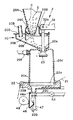
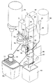
図15は、従来のコーヒー飲料の製造装置を示す。このコーヒー飲料の製造装置は、焙煎されたコーヒー豆を供給口61aからシュート62に供給するコーヒー豆キャニスタ61と、シュート62に供給されたコーヒー豆をコーヒー豆導入口63aから受けてロールで所定の粒度に粉砕するコーヒーミル63と、コーヒーミル63のロールを回転させるミルモータ64と、湯タンク80の湯弁81からチューブ82を介して供給される湯によってコーヒーミル63で粉砕されたコーヒー粉末を抽出し、ロール67から供給されるペーパフィルタ67aでろ過したコーヒー飲料を供給するコーヒー抽出機66と、コーヒー抽出機66から抽出後のコーヒー粉末を受けるかすバケツ69と、コーヒー抽出機66からチューブ83を介して供給されたコーヒー飲料を貯蔵する貯蔵槽60と、砂糖を供給口71aから供給する砂糖キャニスタ71と、クリームを供給口72aから供給するクリームキャニスタ72と、砂糖キャニスタ71あるいはクリームキャニスタ72から供給された砂糖あるいはクリーム、又はこの両者を粉シュート73を介して受け、貯蔵槽60から供給されるコーヒー飲料と混合する混合器74と、カップ受台77上にカップ76を供給するカップディスペンサ75と、貯蔵槽60のコーヒー飲料の過剰分や、カップ76からのこぼれ等を受ける排水バケツ78より構成されている。
【0003】
以上の構成において、砂糖およびクリーム入りのコーヒー飲料の販売要求があると、貯蔵槽60から所定量のコーヒー飲料が混合器74に供給され、これと同時に砂糖キャニスタ71およびクリームキャニスタ72より所定量の砂糖とクリームが混合器74に供給されて、砂糖、クリームがコーヒー飲料と混合されて砂糖およびクリーム入りのコーヒー飲料とされ、カップ76に供給される。
【0004】
一方、貯蔵槽60がコーヒー飲料を貯蔵していないときは、コーヒー豆キャニスタ61が、供給口61aからシュート62を介して所定量(一般には、8〜10g)のコーヒー豆をコーヒーミル63のコーヒー豆導入口63aに供給する。ミルモータ64は販売要求があったときに回転を開始する。従って、コーヒーミル63は供給されたコーヒー豆をロールで所定の粒度で粉砕してコーヒー抽出機66に供給する。コーヒー抽出機66にコーヒー粉末が供給されると、湯タンク80から湯弁81およびチューブ82を介して湯が供給されて抽出が行われ、抽出液がロール67から供給されるペーパフィルタ67aによってろ過されてコーヒー飲料になる。このようにして提供されたコーヒー飲料は、貯蔵槽60を通路の一部として通過して混合器74に供給される。以降、前述した動作の繰り返しによって、砂糖およびクリーム入りのコーヒー飲料となってカップ76に供給される。
【0005】
また、予め所定の粒度に粉砕されて貯蔵されているコーヒー豆を販売要求に応じてコーヒー抽出機66に供給するコーヒー飲料の製造装置がある。
【0006】
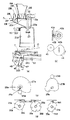
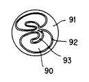
図16は、果肉91に包まれたコーヒー豆90を示し、コーヒー豆90は銀皮(シルバースキン)92によって被われており、一部が93で示すようにコーヒー豆90の内側に巻き込まれている。この部分の銀皮は焙煎後に豆を粉砕して取り出す以外に取り出すことはできない。銀皮がコーヒー飲料に含まれると、味覚として好ましくない渋味を呈することになる。
【0007】
コーヒー飲料の味覚にとって、砂糖およびクリームを入れないブラックコーヒー飲料では、渋味の制御が重要になる。従来、渋味の制御が困難であったために、渋味の少ない濃いブラックコーヒー飲料を提供するときは、通常のコーヒー豆の使用量である8〜10gの2倍の15〜20gのコーヒー豆を使用し、渋味の溶出が遅れることを利用して抽出時間を短くしていた。
【0008】
一方、砂糖入りコーヒー飲料では、渋味が砂糖でマスクされるので、その制御がそれ程重要でなくなる。従って、8〜10gのコーヒー豆を使用しても、抽出時間を少し長くすることによって十分な濃さの砂糖入りコーヒーを得ることができる。
【0009】
また、銀皮は多くの繊維質を含んでおり、コーヒーミルで粉砕されるとき、微細化してペーパフィルタを通過する60〜80メッシュ以下のダスト分になりやすい傾向を有する。
【0010】
このようにしてコーヒー飲料に含まれる銀皮の量が増えると、ブラックコーヒー飲料に加えて、砂糖入りやクリーム入りのコーヒー飲料までが雑味感の伴ったものとなり、味覚を低下させることになる。
【0011】
このような背景により、従来のコーヒー飲料の製造装置では、雑味感を解消する課題を残しながらも、コーヒー豆の使用量を増やして抽出時間を短くすることにより渋味を抑えてブラックコーヒー飲料の味覚を高めている。
【0012】
【発明が解決しようとする課題】
しかし、従来のコーヒー飲料の製造装置によると、ブラックコーヒー飲料については、コーヒー豆の使用量を増やして抽出時間を短くすることにより渋味を抑えているので材料費がコストアップになる。また、コーヒー豆を挽くことによって銀皮が微細化してコーヒー粉末に混入し、これを完全に除去することが困難になるので、ブラックコーヒー飲料、および砂糖入りあるいはクリーム入りのコーヒー飲料の雑味感を解消することができない。
従って、本発明の目的は、材料費のコストアップを抑制して渋味や雑味感の少ないコーヒー飲料を製造するコーヒー飲料の製造装置を提供することにある。
【0013】
本発明の他の目的は、コーヒー粉末に含まれる微細な銀皮を選択的に除去できるコーヒー飲料の製造装置を提供することにある。
【0014】
【課題を解決するための手段】
本発明は上記した目的を達成するため、コーヒー豆を所定の粒度で砕いて得られるコーヒー粉原料を抽出機の前段に位置する粉シュートの放出口から放出させることによって前記抽出機に供給してコーヒー飲料を製造するコーヒー飲料の製造装置において、
前記放出口よりも上方に排気口を有し、前記排気口から排気することにより、前記粉シュートの外側に前記放出口から上方に向かう空気の流れを発生させて前記放出口から放出される前記コーヒー粉原料に混入している銀皮を吸い上げて除去する銀皮除去手段を備えたことを特徴とするコーヒー飲料の製造装置を提供する。
【0015】
また、前記放出口は、前記コーヒー粉原料と湯を混合して前記抽出機に供給する混合室へ前記コーヒー粉原料を投入する粉シュートの放出口であり、前記銀皮除去手段は、前記粉シュートの放出口を囲うドーム状の吸入部を有することが好ましい。また、前記銀皮除去手段は、前記混合室に供給される湯によって発生する湯気を除去するブロアファンの回転に基づいてコーヒー粉原料に混入している銀皮を吸い上げて除去することが好ましい。
また、前記銀皮除去手段は、前記抽出機の蓋部材に前記粉シュートの放出口および前記ドーム状の吸入部を一体的に形成することが好ましい。
【0016】
【発明の実施の形態】
以下、本発明の実施の形態を図面を参照して詳細に説明する。
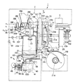
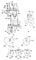
図1は、本発明の実施の形態に係るコーヒー飲料の製造装置の構成図である。このコーヒー飲料の製造装置1は、コーヒー豆を所定の粒度に砕いたひき豆(以下、単にコーヒー豆という)と湯との混合体からコーヒーを抽出する抽出部2と、コーヒー抽出後のコーヒー豆の滓を廃棄する廃棄処理部4と、本装置1の各部に加圧空気を送るエアポンプ5とを有する。
【0017】
抽出部2は、図示しない案内レールによって上下動可能に支持され、上方から供給されたコーヒー豆と湯との混合体を下方へ供給するシリンダ20と、シリンダ20の上方に配置され、コーヒー豆をシリンダ20に供給する粉シュート20Aと、シリンダ20に湯を供給するための湯導入口20Bと、シリンダ20内の湯気およびコーヒー豆に混入した銀皮を除去するための排気口20Cと、粉シュート20Aと一体的に形成されたドーム状のカバー20Dと、カバー20Dと連続的に形成され、シリンダ20内に突出する仕切り板20Eを具備する蓋200と、シリンダ20の下方に配置され、シリンダ20から供給される混合体をろ過するペーパーフィルタ21と、ペーパーフィルタ21でろ過されたコーヒー抽出液を受け入れる飲料受け22を有する。
【0018】
シリンダ20は、蓋200の粉シュート20Aから供給されるコーヒー豆と、湯導入口20Bから供給される湯を受け入れる混合室20bと、コーヒー豆と湯との混合体を下方に設けた排出口20cから排出してコーヒーの抽出が行われる抽出室20dとを連通口20eで連通して形成されている。連通口20eは、バルブ23によって開閉されるようになっており、抽出室20dには、エアポンプ5からの加圧空気を導入する導入口20fを有する。
【0019】
ペーパーフィルタ21は、回動可能な軸21Aにロール状でセットされ、後述する廃棄処理部4の廃棄処理モータ40の駆動により、図1の左方向へ引き出されるように構成されている。また、ペーパーフィルタ21は、基端側が回動可能に支持され、中間部あるいは先端側がロール状のペーパーフィルタ21に常に当接するフィルタ検出レバー21Bと、ペーパーフィルタ21の残量が少なくなってフィルタ検出レバー21Bが回動してスイッチング動作し、ペーパーフィルタ無しを示す検出信号を後述する制御部6に出力して警報出力等に供するマイクロスイッチ等のフィルタ無しセンサ21Cとを備えている。
【0020】
飲料受け22は、上部にシリンダ20が当接する開口22aを有し、開口22aの周囲に混合体が漏れるのを防ぐゴムパッキン22Aを有する。また、端部にペーパーフィルタ21の走行方向を変更するローラ22Bを有し、下部に飲料をカップ側へ供給する飲料供給管22C、および飲料を廃棄する廃棄管22Dを有する。飲料供給管22Cには飲料供給バルブ53が介装されている。
【0021】
また、抽出部2は、抽出モータ24と、両側から出力軸25a,25bをそれぞれ突設し、抽出モータ24の回転数を所定の回転数に減速する減速機25と、一方の出力軸25aの一端をベアリング26aによって支持した支持板26と、一方の出力軸25aに固定されたシリンダカム27Aおよびバルブカム27Bと、シリンダ20を駆動するシリンダ駆動板28Aと、バルブ23を駆動するバルブ駆動板28Bと、シリンダ駆動板28Aに取り付けられたシリンダカムフォロア29Aと、バルブ駆動板28Bに取り付けられたバルブカムフォロア29Bと、シリンダ駆動板28Aに取り付けられた係止部材28aとバルブ駆動板28Bに取り付けられた係止部材28bとに両端がそれぞれ係止され、シリンダ駆動板28Aとバルブ駆動板28Bとを互いに引き寄せてシリンダカムフォロア29Aおよびバルブカムフォロア29Bをシリンダカム27Aおよびバルブカム27Bにそれぞれ当接させる引張コイルバネ30と、シリンダ20とシリンダ駆動板28Aとを連結する複数の連結部材31A,31B,および31Cと、バルブ23を先端側のピン32aによって回動可能に連結したレバー32と、バルブ駆動板28Bに取り付けられ、ピン32bによってレバー32を回動可能に連結した連結部材33と、レバー32の後端側とバルブ駆動板28Bに取り付けられた係止部材28cとに両端がそれぞれ係止された引張コイルバネ34とを備えている。この抽出部2は、出力軸25a,25bおよび出力軸41aがそれぞれ1回転することにより攪拌工程,抽出工程,滓廃棄工程の一連の工程が終了するように構成されている。
【0022】
減速機25は、他方の出力軸25b側に各工程の細部を検出する工程検出機構を有する。すなわち、減速機25の他方の出力軸25bには、第1,第2および第3の工程検出板35A,35B,および35Cを取り付け、第1,第2および第3の工程検出板35A,35B,および35Cの周囲には、第1,第2および第3の工程検出板35A,35B,および35Cの回転位置を検出(例えば、遮光によってOFF)するホトセンサ等の第1,第2および第3の工程検出センサ36A,36B,および36Cを配置している。
【0023】
エアポンプ5には、抽出室20dの導入口20fと飲料受け22に通じるエアパイプ52が接続され、エアパイプ52には、抽出室20dの導入口20fの前段に上部空気電磁弁50が、また、飲料受け22の前段に下部空気電磁弁51がそれぞれ設けられている。
【0024】
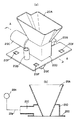
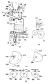
図2(a)は、蓋200を示し、蓋200はシリンダ20に設けられる固定用の係合突起(図示せず)と係合する固定穴20Fと、バルブ23を連通させるための切欠き部20Gを有する。また、カバー20Dの上部は排気口20Cへの空気の流れを円滑化するために曲線的(ドーム状)に形成されている。
【0025】
図2(b)は、図2(a)における蓋200のA−A断面を示し、カバー20Dに一体的に形成されている排気口20Cには配管20gを介してブロアファン20Hが接続されている。この排気口20Cは、粉シュート20Aの下端(コーヒー豆の放出口)より上方に位置するように設けられている。
【0026】
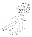
図3は、図1のA−A断面を示し、シリンダカム27Aおよびバルブカム27Bは、キー25cによって一方の出力軸25aに固定されており、シリンダカム27Aおよびバルブカム27Bのカム面は、同図のように形成されている。
【0027】
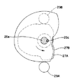
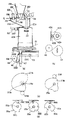
図4は、工程検出機構の斜視図である。第1の工程検出板35Aは、2ヵ所に約90度の突部35aを形成し、第2の工程検出板35Bは、4ヵ所に約70度の突部35aを形成し、第3の工程検出板35Cは、1ヵ所に約180度の突部35aを形成している。
【0028】
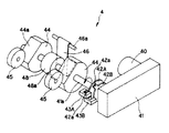
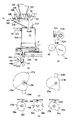
図5は、廃棄処理部4の要部斜視図である。廃棄処理部4は、廃棄処理モータ40と、廃棄処理モータ40の回転数を所定の回転数に減速する減速機41と、減速機41の出力軸41aに取り付けられた廃棄管開検出板42A,および廃棄管閉検出板42Bと、廃棄管開検出板42Aの突部42aによる遮光(例えばOFF)によって廃棄管22Dの開状態(待機状態)を示すOFF信号を出力するホトセンサ等の廃棄管開検出センサ43Aと、廃棄管閉検出板42Bの突部42aによる遮光(例えばOFF)によって廃棄管22Dの閉状態を示すOFF信号を出力するホトセンサ等の廃棄管閉検出センサ43Bと、円周上に切欠き部44aを有して出力軸41aに取り付けられ、ペーパーフィルタ21を一定長さ分送り出す一対のフィルタ送りローラ44,44と、ペーパーフィルタ21を一対のフィルタ送りローラ44,44側に図示しないバネによって押圧する一対のガイドローラ45,45と、支軸46aによって回動可能に支持され、廃棄管22Dを固定板(図1参照)47との間で押圧閉止する板バネ等からなる押圧板46と、出力軸41aに取り付けられ、押圧板46を回動させる円周上に突部48aを有した押圧カム48を有する。
【0029】
図6は、本発明のコーヒー飲料の製造装置の制御ブロック図を示し、コーヒー飲料の製造装置の各部を制御する制御部6に、廃棄管開検出センサ43A、廃棄管閉検出センサ43B、第1,第2および第3の工程検出センサ36A,36B,36C、フィルタ無しセンサ21C、エアポンプ5、上部空気電磁弁50、下部空気電磁弁51、飲料供給バルブ53、抽出モータ24、廃棄処理モータ40、およびブロアファン20Hを各々接続し、更に、コーヒー飲料の販売を制御する主制御部7を接続している。
【0030】
制御部6は、主制御部7から販売信号が入力されると、抽出モータ24,廃棄処理モータ40,およびエアポンプ5を制御して飲料抽出制御、すなわち、攪拌工程,抽出工程,滓廃棄工程の一連の工程を行わせる。
【0031】
次に、図7から図14を参照しつつ本発明のコーヒー飲料の製造装置1の動作を説明する。
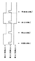
図7は、第1,第2および第3の工程検出センサ36A,36B,36Cの出力信号を示す図である。
図8から図14は、本装置1の動作を示し、同図(a) は主要部(シリンダ20、バルブ13等)の位置を示す図、同図(b) は廃棄管開検出板42Aおよび廃棄管閉検出板42B、およびフィルタ送りローラ44の位置を示す図、同図(c) はシリンダカム27Aおよびバルブカム27Bの位置を示す図、同図(d) は第1,第2および第3の工程検出板35A,35B,35Cの位置を示す図である。
【0032】
(1) 待機状態(図8参照)
待機状態においては、本装置1の主要部は、図7に示す待機位置P1 にあり、図8に示す状態にある。すなわち、第1,第2および第3の工程検出センサ36A,36B,および36CはONとなり、廃棄管開検出センサ43AはOFF、廃棄管閉検出センサ43BはONとなっている。フィルタ送りローラ44とガイドローラ45との間に若干の隙間を有しており、フィルタ送りローラ44が回転してもペーパーフィルタ21は、全く移動しないようになっている。押圧板46は、廃棄管22Dの弾性力によって押圧カム48に当接している。
【0033】
(2) 攪拌工程(図9,図10参照)
制御部6は、主制御部7から販売信号が入力されると、第2の工程検出センサ36BがONのとき、第1,第3の工程検出センサ36A,36CのONに基づいて待機位置P1 から攪拌位置P2 への移行動作を行う。すなわち、制御部6は、廃棄処理モータ40を正転駆動(図9(a) において出力軸41aが左回転する駆動)する。廃棄処理モータ40の駆動トルクが減速機41を介して出力軸41aに伝達され、出力軸41aが約60°正転(図9(a) において左回転)して、図9(a) に示すように、押圧カム48の突部48aが押圧板46を押圧することにより、廃棄管22Dが押圧板46と固定板47との間で閉止される。廃棄管閉検出センサ43Bは、廃棄管閉検出板42Bの突部42aによって遮光され、OFF信号を制御部6に出力する。制御部6は、廃棄管閉検出センサ43BからのOFF信号に基づいて廃棄処理モータ40の駆動を停止する。
【0034】
続いて制御部6は、抽出モータ24を正転駆動(図10(d) において出力軸25bが左回転する駆動)する。抽出モータ24の駆動トルクが減速機25を介して出力軸25a,25bに伝達され、出力軸25a,25bが正転(図10(d) において左回転)して、図10(c) に示すように、シリンダカム27Aおよびバルブカム27Bが正転することにより、シリンダ駆動板28Aおよびバルブ駆動板28Bが下降する。シリンダ駆動板28Aが下降すると、複数の連結部材31A,31B,31Cを介してシリンダ20が下降し、抽出室20dの下端がペーパーフィルタ21を飲料受け22へ圧接する。一方、バルブ駆動板28Bが下降すると、連結部材33,レバー32を介してバルブ23も下降する。第1の工程検出センサ36Aは、第1の工程検出板35Aによって遮光され、OFF信号を制御部6に出力する。続いて、第2の工程検出センサ36Bは、ON信号を制御部6に出力する。制御部6は、第2の工程検出センサ36BがONのとき、第1の工程検出センサ36AのOFFに基づいて抽出モータ24の駆動を停止する。本装置1の主要部は、図7に示す攪拌位置P2 に到達し、図10に示す状態となる。図10に示す状態では、同図(d) に示すように、第2,第3の工程検出センサ36B,36Cは、第2,第3の工程検出板35B,35Cの突部35aによって遮光されていないので、ON信号を制御部6にそれぞれ出力している。
【0035】
制御部6は、第2の工程検出センサ36BのONのとき、第1の工程検出センサ36AのOFF、第3の工程検出センサ36CのONに基づいて攪拌工程を行う。すなわち、制御部6は、コーヒー豆および湯の供給要求信号を主制御部7に出力する。この主制御部7の制御に基づいて粉シュート20Aからコーヒー豆が供給され、湯導入口20Bから湯が供給されて混合室20bで混合される。制御部6は、コーヒー豆と湯の供給に合わせて、飲料供給バルブ53を閉じ、さらに下部空気電磁弁51を開き、エアポンプ5を駆動する。エアポンプ5は、加圧空気をエアパイプ52を介して飲料受け22に送る。この加圧空気は、ペーパーフィルタ21を通過して抽出室20d内へ流入する。この加圧空気が抽出室20d内の混合体中を通過する際、その気泡の流れが混合体を攪拌するように作用する。ペーパーフィルタ21の下方から加圧空気を供給することで、コーヒー豆に含まれる成分の湯への溶出が助長され、短時間で飲料を抽出することができる。
【0036】
図11は、コーヒー豆の供給を示し、主制御部7から制御部6に販売信号が出力されるとブロアファン20Hが回転し、カバー20Dの内部に矢印で示す空気の流れを発生させる。この空気流が砕かれたコーヒー豆Cと銀皮Sに作用し、その重さの差により軽い銀皮Sは空気流に乗り、仕切り板20Eに沿ってカバー20Dの上方に移動し、排気口20Cからカバー20Dの外部に吸い出され、排気口20Cに接続される配管(図示せず)を介してかすバケツ等のかす処理部に誘導される。一方、重いコーヒー豆Cは、粉シュート20Aからほぼ垂直に落下する。ブロアファン20Hはコーヒー豆の供給後も回転し、湯導入口20Bから供給される湯によって発生する湯気(図示せず)を上記した空気流に基づいて排気口20Cからカバー20Dの外部に吸い出して除去する。
【0037】
(3) 抽出工程(図12参照)
制御部6は、タイマーで設定された攪拌時間が経過すると、抽出モータ24を正転駆動する。抽出モータ24の駆動トルクが減速機25を介して出力軸25a,25bに伝達され、シリンダカム27A,バルブカム27Bが正転する。図12(c) に示すように、シリンダカム27Aのカム半径は変化しないので、シリンダ20は上下動しないが、バルブカム27Bのカム半径は大きくなるので、バルブ23が上昇し、図12(a) に示すように、連通口20eを閉じる。第3の工程検出センサ36Cは、第3の工程検出板35Cによって遮光され、OFF信号を制御部6に出力する。続いて第2の工程検出センサ36Bは、ON信号を制御部6に出力する。制御部6は、第2の工程検出センサ36BがONのとき、第3の工程検出センサ36CのOFFに基づいて抽出モータ24の駆動を停止する。本装置1の主要部は、図7に示す抽出位置P3 に到達し、図12に示す状態となる。図12に示す状態では、同図(d) に示すように、第1,2の工程検出センサ36A,36BはONになる。
【0038】
制御部6は、第2の工程検出センサ36BのONのとき、第1の工程検出センサ36AのON、第3の工程検出センサ36CのOFFに基づいて抽出工程を行う。すなわち、制御部6は、上部空気電磁弁50を開け、下部空気電磁弁51を閉じ、飲料供給バルブ53を開き、エアポンプ5を駆動して、エアポンプ5からの加圧空気をエアパイプ52を介して抽出室20dの上方の導入口20fから供給する。抽出室20d内の混合体は、エアポンプ5からの加圧空気によって下方へ圧送され、ペーパーフィルタ21でろ過される。ペーパーフィルタ21でろ過された飲料は、飲料受け22,飲料供給管22Cを介してカップ側へ供給される。抽出室20dに加圧空気を送ることで、抽出室20d内の気圧が増加して混合体がペーパーフィルタ21側に押し下げられるので、短時間で混合体が飲料と滓に分離され、効率良くろ過することができる。
【0039】
(4) 滓廃棄処理(図13,図14参照)
タイマで設定された抽出時間が経過すると、制御部6は、抽出モータ24を正転駆動する。抽出モータ24の駆動トルクが減速機25を介して出力軸25a,25bに伝達され、シリンダカム27A,バルブカム27Bが正転し、シリンダ駆動板28Aおよびバルブ駆動板28Bが上昇し、シリンダ20およびバルブ23が最上位まで上昇する。第1,第3の工程検出センサ36A,36Cは、第1,第3の工程検出板35A,35Cによって遮光され、OFF信号を制御部6に出力する。続いて第2の工程検出センサ36Bは、ON信号を制御部6に出力する。制御部6は、第2の工程検出センサ36BがONのとき、第1,第3の工程検出センサ36A,36CのOFFに基づいて抽出モータ24の駆動を停止する。本装置1の主要部は、図7に示す滓廃棄位置P4 に到達し、図13に示す状態となる。図13の状態では、同図(d) に示すように、第2の工程検出センサ36BはONとなり、ペーパーフィルタ21上にはコーヒー豆の滓7が残る。
制御部6は、第2の工程検出センサ36BがONのとき、第1,第3の工程検出センサ36A,36CのOFFに基づいて滓廃棄工程を行う。すなわち、制御部6は、廃棄処理モータ40を正転駆動する。廃棄処理モータ40の駆動トルクが減速機41を介して出力軸41aに伝達され、出力軸41aが正転し、フィルタ送りローラ44が回転してペーパーフィルタ21を引き出す。ペーパーフィルタ21上の滓7がローラ22Bを通過する際、図14(a) の想像線で示すように滓7が折れてペーパーフィルタ21から離れ、廃棄バケツ(図示せず)へ落下する。廃棄管開検出センサ43Aは、廃棄管開検出板42Aによって遮光され、OFF信号を制御部6に出力する。制御部6は、廃棄管開検出センサ43AからのOFF信号に基づいて廃棄処理モータ40の駆動を停止する。本装置1の主要部は、図14に示す状態となる。
【0040】
上記した実施の形態によると、粉シュート20Aの近傍にブロアファン20Hと接続された排気口20Cを設け、粉シュート20Aから供給されるコーヒー豆に混入している銀皮をブロアファン20Hの回転に基づいて吸い上げるので、通常のコーヒー豆の使用量(8〜10g)でも渋みの少ないコーヒー飲料を提供することができる。また、排気口20Cへの銀皮の吸引を促すようにドーム状のカバー20Dを蓋200に一体的に形成したことにより、ブロアファン20Hの回転に基づく排気口20Cの吸引効率が向上し、コーヒー豆と銀皮の重さの違いによる銀皮の選択的な除去を効率良く行うことができる。このドーム状のカバー20Dは蓋200の製造時に同時に形成できるので、加工に要するコスト増も僅かである。
【0041】
また、ブロアファン20Hは、シリンダ20に発生する湯気の除去に用いるものを銀皮除去に兼用しても良く、この場合には構成の簡素化が図れ、飲料抽出装置の製造コストを抑えることができる。
【0042】
なお、本発明は、上記実施の形態に限定されず、種々な実施の形態が可能である。例えば、工程を検出するセンサとしては、絶対値型のエンコーダを用いてもよい。
【0043】
【発明の効果】
以上説明した通り、本発明のコーヒー飲料の製造装置によると、粉シュートから供給されるコーヒー粉原料に混入している銀皮を吸い上げて除去するようにしたため、材料費のコストアップを抑えながら渋みや雑味感を低減する。また、コーヒー豆に含まれる微細な銀皮を選択的に除去することができる。
【図面の簡単な説明】
【図1】本発明の実施の形態におけるコーヒー飲料の製造装置を示す斜視図。
【図2】 (a) は、粉シュートを有する蓋の斜視図であり、(b) は、(a) のA−A部における断面図である。
【図3】図1のA−A部の断面図。
【図4】本発明の実施の形態における工程検出機構を示す斜視図。
【図5】本発明の実施の形態における廃棄処理部を示す斜視図。
【図6】本発明の実施の形態における制御ブロック図。
【図7】本発明の実施の形態における第1,第2,および第3の工程検出センサの出力信号に基づくタイミングチャート。
【図8】本発明の実施の形態におけるコーヒー飲料の製造装置の待機状態を示す説明図。
【図9】本発明の実施の形態におけるコーヒー飲料の製造装置の廃棄管の閉止状態を示す説明図。
【図10】本発明の実施の形態におけるコーヒー飲料の製造装置の攪拌工程を示す説明図。
【図11】銀皮の除去を示す説明図。
【図12】本発明の実施の形態におけるコーヒー飲料の製造装置の抽出工程を示す説明図。
【図13】本発明の実施の形態におけるコーヒー飲料の製造装置の滓廃棄処理工程の開始状態を示す説明図。
【図14】本発明の実施の形態におけるコーヒー飲料の製造装置の滓廃棄処理工程の終了状態を示す説明図。
【図15】従来のコーヒ飲料の製造装置を示す説明図。
【図16】コーヒー豆を示す説明図。
【符号の説明】
1,コーヒー飲料の製造装置
2,抽出部
4,廃棄処理部
5,エアポンプ
6,制御部
20,シリンダ
20A,粉シュート
20B,湯導入口
20C,排気口
20D,カバー
20E,仕切り板
20F,固定穴
20G,切欠き部
20H,ブロアファン
20b,混合室
20c,排出口
20d,抽出室
20e,連通口
20f,導入口
20g,配管
21,ペーパーフィルタ
21A,軸
21B,フィルタ検出レバー
21C,フィルタ無しセンサ
22,飲料受け
22A,ゴムパッキン
22B,ローラ
22C,飲料供給管
22D,廃棄管
22a,開口
23,バルブ
24,抽出モータ
25,減速機
25a,出力軸
25b,出力軸
25c,キー
26,支持板
26a,ベアリング
27A,シリンダカム
27B,バルブカム
28A,シリンダ駆動板
28B,バルブ駆動板
28a,係止部材
28b,係止部材
29A,シリンダカムフォロア
29B,バルブカムフォロア
30,引張コイルバネ
31A,連結部材
31B,連結部材
31C,連結部材
32a,ピン
32,レバー
32b,ピン
33,連結部材
34,引張コイルバネ
35A,第1の工程検出板
35B,第2の工程検出板
35C,第3の工程検出板
35a,突部
36A,第1の工程検出センサ
36B,第2の工程検出センサ
36C,第3の工程検出センサ
40,廃棄処理モータ
41,減速機
41a,出力軸
42A,廃棄管開検出板
42B,廃棄管閉検出板
42a,突部
43A,廃棄管開検出センサ
43B,廃棄管閉検出センサ
44,フィルタ送りローラ
44a,切欠き部
45,ガイドローラ
46a,支軸
47,固定板
46,押圧板
48,押圧カム
48a,突部
50,上部空気電磁弁
51,下部空気電磁弁
52,エアパイプ
53,飲料供給バルブ
60,貯蔵槽
61,コーヒー豆キャニスタ
61a,供給口
62,シュート
63,コーヒーミル
63a,コーヒー豆導入口
64,ミルモータ
66,コーヒー抽出機
67,ロール
67a,ペーパーフィルタ
69,かすバケツ
71,砂糖キャニスタ
71a,供給口
72,クリームキャニスタ
72a,供給口
73,粉シュート
74,混合器
75,カップディスペンサ
76,カップ
77,カップ受台
78,排水バケツ
80,湯タンク
81,湯弁
82,チューブ
83,チューブ
90,コーヒー豆
91,果肉
92,銀皮
93,銀皮
200,蓋[0001]
BACKGROUND OF THE INVENTION
The present invention relates to an apparatus for producing a coffee beverage, and more particularly to an apparatus for producing a coffee beverage capable of removing the bitterness and a bitter taste contained in an extract of coffee.
[0002]
[Prior art]
FIG. 15 shows a conventional coffee beverage production apparatus. The coffee beverage manufacturing apparatus includes a
[0003]
In the above configuration, when there is a demand for selling coffee beverages containing sugar and cream, a predetermined amount of coffee beverage is supplied from the
[0004]
On the other hand, when the
[0005]
There is also a coffee beverage manufacturing apparatus that supplies coffee beans that have been crushed and stored in advance to a predetermined particle size to a
[0006]
FIG. 16 shows
[0007]
For the taste of coffee beverages, the control of astringency is important for black coffee beverages without sugar and cream. Conventionally, since it was difficult to control astringency, when providing a dark black coffee beverage with less astringency, 15 to 20 g of coffee beans, which is twice the usual amount of coffee beans used, 8 to 10 g, is used. The extraction time was shortened by taking advantage of the delayed elution of astringency.
[0008]
On the other hand, in a coffee drink with sugar, the astringency is masked with sugar, so its control becomes less important. Therefore, even if 8 to 10 g of coffee beans are used, a sufficiently strong sugar-containing coffee can be obtained by slightly extending the extraction time.
[0009]
Silver skin contains a lot of fibers, and when pulverized by a coffee mill, it tends to be fine and become dust of 60 to 80 mesh or less passing through a paper filter.
[0010]
If the amount of silver crust contained in the coffee beverage is increased in this way, in addition to the black coffee beverage, the coffee beverage containing sugar or cream is accompanied by a sense of taste, and the taste is lowered. .
[0011]
With such a background, in the conventional coffee beverage production apparatus, while remaining the problem of eliminating the taste of taste, the astringency is reduced by increasing the amount of coffee beans used and shortening the extraction time, thereby reducing the black coffee beverage To enhance the taste.
[0012]
[Problems to be solved by the invention]
However, according to the conventional coffee beverage manufacturing apparatus, the black coffee beverage increases the amount of coffee beans used and shortens the extraction time, thereby reducing the astringency and increasing the material cost. In addition, grinding the coffee beans makes the silver crust finer and mixed into the coffee powder, making it difficult to completely remove it. Therefore, it is difficult to completely remove black coffee and sugar or cream coffee. Can not be resolved.
Accordingly, an object of the present invention is to provide a coffee beverage production apparatus that produces a coffee beverage with less astringency and a bitter taste while suppressing an increase in material costs.
[0013]
Another object of the present invention is to provide a coffee beverage production apparatus capable of selectively removing fine silver crust contained in coffee powder.
[0014]
[Means for Solving the Problems]
In order to achieve the above-mentioned object, the present invention locates the coffee powder raw material obtained by crushing coffee beans with a predetermined particle size in the front stage of the extractor.Powder chuteIn a coffee beverage production apparatus for producing a coffee beverage by supplying to the extractor by discharging from a discharge port,
The exhaust port has an exhaust port above the discharge port, and exhausting from the exhaust port generates an air flow upward from the discharge port on the outside of the powder chute.There is provided a coffee beverage production apparatus comprising silver skin removing means for sucking and removing silver skin mixed in the coffee powder raw material discharged from the discharge port.
[0015]
In addition, the discharge portMix coffee powder ingredients and hot waterSaidTo the mixing chamber supplied to the extractorSaidIt is the outlet of the powder chute that feeds the coffee powder ingredients,SaidSilver skin removal meansSaidIt is preferable to have a dome-shaped suction part surrounding the discharge port of the powder chute. Also,SaidSilver skin removal meansSaidBased on the rotation of a blower fan that removes steam generated by the hot water supplied to the mixing chamber, the silver crust mixed in the coffee powder raw material is sucked up and removed.It is preferable.
Also,The silver skin removing means isSaidFor the lid of the extractorSaidPowder chute outlet andSaidIt is preferable to form the dome-shaped suction part integrally.
[0016]
DETAILED DESCRIPTION OF THE INVENTION
Hereinafter, embodiments of the present invention will be described in detail with reference to the drawings.
FIG. 1 is a configuration diagram of a coffee beverage manufacturing apparatus according to an embodiment of the present invention. The coffee beverage production apparatus 1 includes an
[0017]
The
[0018]
The
[0019]
The
[0020]
The
[0021]
Further, the
[0022]
The
[0023]
The
[0024]
FIG. 2A shows the
[0025]
FIG. 2B shows an AA cross section of the
[0026]
3 shows a cross section taken along the line AA of FIG. 1. The
[0027]
FIG. 4 is a perspective view of the process detection mechanism. The first
[0028]
FIG. 5 is a perspective view of a main part of the disposal processing unit 4. The waste processing unit 4 includes a
[0029]
FIG. 6 shows a control block diagram of the coffee beverage production apparatus of the present invention. The
[0030]
When the sales signal is input from the
[0031]
Next, the operation of the coffee beverage production apparatus 1 according to the present invention will be described with reference to FIGS.
FIG. 7 is a diagram illustrating output signals of the first, second, and third
FIGS. 8 to 14 show the operation of the apparatus 1. FIG. 8 (a) shows the positions of the main parts (
[0032]
(1) Standby state (see Fig. 8)
In the standby state, the main part of the apparatus 1 is the standby position P shown in FIG.1And is in the state shown in FIG. That is, the first, second, and third
[0033]
(2) Stirring process (see Fig. 9 and Fig. 10)
When the sales signal is input from the
[0034]
Subsequently, the
[0035]
When the second
[0036]
FIG. 11 shows the supply of coffee beans. When a sales signal is output from the
[0037]
(3) Extraction process (see Fig. 12)
When the stirring time set by the timer has elapsed, the
[0038]
When the second
[0039]
(4) Waste disposal processing (see Fig. 13 and Fig. 14)
When the extraction time set by the timer has elapsed, the
When the second
[0040]
According to the above-described embodiment, the
[0041]
In addition, the
[0042]
In addition, this invention is not limited to the said embodiment, Various embodiment is possible. For example, an absolute value type encoder may be used as a sensor for detecting a process.
[0043]
【The invention's effect】
As described above, according to the coffee beverage manufacturing apparatus of the present invention, the silver crust mixed in the coffee powder raw material supplied from the powder chute is sucked up and removed, so it is astringent while suppressing an increase in material costs. And reduce taste. Moreover, the fine silver skin contained in coffee beans can be selectively removed.
[Brief description of the drawings]
FIG. 1 is a perspective view showing a coffee beverage manufacturing apparatus according to an embodiment of the present invention.
FIG. 2A is a perspective view of a lid having a powder chute, and FIG. 2B is a cross-sectional view taken along a line AA in FIG.
3 is a cross-sectional view taken along a line AA in FIG.
FIG. 4 is a perspective view showing a process detection mechanism in the embodiment of the present invention.
FIG. 5 is a perspective view showing a disposal processing unit according to the embodiment of the present invention.
FIG. 6 is a control block diagram according to the embodiment of the present invention.
FIG. 7 is a timing chart based on output signals of the first, second, and third process detection sensors in the embodiment of the present invention.
FIG. 8 is an explanatory diagram showing a standby state of the coffee beverage manufacturing apparatus according to the embodiment of the present invention.
FIG. 9 is an explanatory diagram showing a closed state of a waste pipe of the coffee beverage manufacturing apparatus according to the embodiment of the present invention.
FIG. 10 is an explanatory view showing an agitation process of the coffee beverage production apparatus in the embodiment of the present invention.
FIG. 11 is an explanatory view showing removal of silver skin.
FIG. 12 is an explanatory diagram showing an extraction process of the coffee beverage manufacturing apparatus in the embodiment of the present invention.
FIG. 13 is an explanatory diagram showing a start state of a waste disposal process of the coffee beverage manufacturing apparatus according to the embodiment of the present invention.
FIG. 14 is an explanatory view showing the end state of the mash disposal process of the coffee beverage manufacturing apparatus in the embodiment of the present invention.
FIG. 15 is an explanatory view showing a conventional coffee beverage manufacturing apparatus.
FIG. 16 is an explanatory diagram showing coffee beans.
[Explanation of symbols]
1, Coffee beverage production equipment
2, Extraction unit
4.Disposal processing department
5, Air pump
6, control unit
20, cylinder
20A, powder chute
20B, hot water inlet
20C, exhaust port
20D, cover
20E, partition plate
20F, fixing hole
20G, notch
20H, blower fan
20b, mixing chamber
20c, outlet
20d, extraction chamber
20e, communication port
20f, inlet
20g, piping
21, paper filter
21A, shaft
21B, filter detection lever
21C, sensor without filter
22. Beverage receptacle
22A, rubber packing
22B, Roller
22C, beverage supply pipe
22D, waste pipe
22a, opening
23, valve
24, extraction motor
25, reducer
25a, output shaft
25b, output shaft
25c, key
26, support plate
26a, bearing
27A, cylinder cam
27B, valve cam
28A, cylinder drive plate
28B, valve drive plate
28a, locking member
28b, locking member
29A, cylinder cam follower
29B, valve cam follower
30 、 Tension coil spring
31A, connecting member
31B, connecting member
31C, connecting member
32a, pin
32, lever
32b, pin
33, connecting member
34, tension coil spring
35A, first process detection plate
35B, second process detection plate
35C, third process detection plate
35a, protrusion
36A, first process detection sensor
36B, second process detection sensor
36C, third process detection sensor
40, disposal motor
41, reducer
41a, output shaft
42A, waste pipe open detection plate
42B, waste pipe closing detection plate
42a, protrusion
43A, waste pipe open detection sensor
43B, waste pipe closure detection sensor
44, filter feed roller
44a, notch
45, guide roller
46a, spindle
47, fixed plate
46, pressing plate
48, pressing cam
48a, protrusion
50, upper air solenoid valve
51, lower air solenoid valve
52, air pipe
53, Beverage supply valve
60, storage tank
61, coffee bean canister
61a, supply port
62, chute
63, coffee mill
63a, coffee bean inlet
64, mill motor
66, coffee extractor
67, roll
67a, paper filter
69, debris bucket
71, sugar canister
71a, supply port
72, cream canister
72a, supply port
73, powder chute
74, mixer
75, cup dispenser
76, cup
77, cup holder
78, drain bucket
80, hot water tank
81, hot water valve
82, tube
83, tube
90, coffee beans
91, pulp
92, Silver skin
93, silver skin
200, lid
Claims (4)
前記放出口よりも上方に排気口を有し、前記排気口から排気することにより、前記粉シュートの外側に前記放出口から上方に向かう空気の流れを発生させて前記放出口から放出される前記コーヒー粉原料に混入している銀皮を吸い上げて除去する銀皮除去手段を備えたことを特徴とするコーヒー飲料の製造装置。In a coffee beverage production apparatus for producing a coffee beverage by supplying a coffee powder raw material obtained by crushing coffee beans to a predetermined particle size from a discharge port of a powder chute located in the preceding stage of the extractor to supply the extractor ,
The exhaust port has an exhaust port above the discharge port, and exhausts from the exhaust port, thereby generating an air flow upward from the discharge port on the outside of the powder chute and discharging from the discharge port. An apparatus for producing a coffee beverage, comprising silver skin removing means for sucking and removing silver skin mixed in a coffee powder raw material.
前記銀皮除去手段は、前記粉シュートの放出口を囲うドーム状の吸入部を有する構成の請求項第1項記載のコーヒー飲料の製造装置。Before Kiho outlet is outlet powder chute to introduce the coffee grounds the raw material into the mixing chamber supplied to the extractor by mixing the coffee powder raw material and hot water,
The apparatus for producing a coffee beverage according to claim 1, wherein the silver skin removing means has a dome-shaped suction portion surrounding the discharge port of the powder chute.
Priority Applications (1)
| Application Number | Priority Date | Filing Date | Title |
|---|---|---|---|
| JP16006897A JP3649859B2 (en) | 1997-06-17 | 1997-06-17 | Coffee beverage production equipment |
Applications Claiming Priority (1)
| Application Number | Priority Date | Filing Date | Title |
|---|---|---|---|
| JP16006897A JP3649859B2 (en) | 1997-06-17 | 1997-06-17 | Coffee beverage production equipment |
Publications (2)
| Publication Number | Publication Date |
|---|---|
| JPH114769A JPH114769A (en) | 1999-01-12 |
| JP3649859B2 true JP3649859B2 (en) | 2005-05-18 |
Family
ID=15707205
Family Applications (1)
| Application Number | Title | Priority Date | Filing Date |
|---|---|---|---|
| JP16006897A Expired - Fee Related JP3649859B2 (en) | 1997-06-17 | 1997-06-17 | Coffee beverage production equipment |
Country Status (1)
| Country | Link |
|---|---|
| JP (1) | JP3649859B2 (en) |
Families Citing this family (5)
| Publication number | Priority date | Publication date | Assignee | Title |
|---|---|---|---|---|
| JP2003267496A (en) * | 2002-03-12 | 2003-09-25 | Amekaze:Kk | Placing table for coffee extracting device |
| JP4631985B2 (en) * | 2009-01-09 | 2011-02-16 | 富士電機リテイルシステムズ株式会社 | Beverage extractor |
| JP6467615B1 (en) * | 2017-08-07 | 2019-02-13 | 株式会社Tree Field | Beverage production apparatus and control method |
| JP6467614B1 (en) * | 2017-08-07 | 2019-02-13 | 株式会社Tree Field | Beverage production apparatus and control method |
| CN114767535B (en) * | 2022-04-19 | 2023-06-27 | 安徽美邸康药业有限公司 | Automatic recovery device of waste gas for plaster decoction |
-
1997
- 1997-06-17 JP JP16006897A patent/JP3649859B2/en not_active Expired - Fee Related
Also Published As
| Publication number | Publication date |
|---|---|
| JPH114769A (en) | 1999-01-12 |
Similar Documents
| Publication | Publication Date | Title |
|---|---|---|
| JP5220337B2 (en) | High temperature beverage preparation apparatus and method | |
| US5845561A (en) | Apparatus for preparing a coffee beverage | |
| JP3649859B2 (en) | Coffee beverage production equipment | |
| JP3796017B2 (en) | Beverage extractor | |
| JP5338508B2 (en) | Cup-type beverage vending machine | |
| JP3900056B2 (en) | Tea-based beverage supply device tea leaf supply device | |
| CN114340453A (en) | Beverage supply device | |
| JP3649860B2 (en) | Beverage extractor | |
| JP3845740B2 (en) | Beverage production equipment | |
| JP3649858B2 (en) | Beverage extractor | |
| JP2002170157A (en) | Drink percolator | |
| KR960009233B1 (en) | Coffee Maker | |
| JP6702381B2 (en) | Beverage supply device | |
| JP3931779B2 (en) | Tea-based beverage cooking equipment | |
| JP3778725B2 (en) | Beverage supply equipment | |
| CN115868837B (en) | Food processor, method of controlling the same, apparatus for controlling the same, and readable storage medium storing the apparatus | |
| JPH0642314Y2 (en) | Beverage extractor for vending machines | |
| JP3778688B2 (en) | Beverage extractor | |
| CN1053333C (en) | Coffee making machine | |
| JPH1166420A (en) | Automatic vending machine for extracted drink | |
| JPH0157398B2 (en) | ||
| JP2736203B2 (en) | Extraction filtration method in vending machine | |
| KR200160952Y1 (en) | Vending Machine of Vending Machine | |
| JPH07234970A (en) | Extraction filtering device for vending machines | |
| JP2008017980A (en) | Coffee mill apparatus |
Legal Events
| Date | Code | Title | Description |
|---|---|---|---|
| A977 | Report on retrieval |
Free format text: JAPANESE INTERMEDIATE CODE: A971007 Effective date: 20040715 |
|
| A131 | Notification of reasons for refusal |
Free format text: JAPANESE INTERMEDIATE CODE: A131 Effective date: 20040727 |
|
| A521 | Written amendment |
Free format text: JAPANESE INTERMEDIATE CODE: A523 Effective date: 20040927 |
|
| TRDD | Decision of grant or rejection written | ||
| A01 | Written decision to grant a patent or to grant a registration (utility model) |
Free format text: JAPANESE INTERMEDIATE CODE: A01 Effective date: 20050208 |
|
| A61 | First payment of annual fees (during grant procedure) |
Free format text: JAPANESE INTERMEDIATE CODE: A61 Effective date: 20050216 |
|
| FPAY | Renewal fee payment (prs date is renewal date of database) |
Free format text: PAYMENT UNTIL: 20090225 Year of fee payment: 4 |
|
| LAPS | Cancellation because of no payment of annual fees |