JP3845740B2 - Beverage production equipment - Google Patents
Beverage production equipment Download PDFInfo
- Publication number
- JP3845740B2 JP3845740B2 JP2002086438A JP2002086438A JP3845740B2 JP 3845740 B2 JP3845740 B2 JP 3845740B2 JP 2002086438 A JP2002086438 A JP 2002086438A JP 2002086438 A JP2002086438 A JP 2002086438A JP 3845740 B2 JP3845740 B2 JP 3845740B2
- Authority
- JP
- Japan
- Prior art keywords
- cup
- beverage
- lid
- coffee
- unit
- Prior art date
- Legal status (The legal status is an assumption and is not a legal conclusion. Google has not performed a legal analysis and makes no representation as to the accuracy of the status listed.)
- Expired - Fee Related
Links
- 235000013361 beverage Nutrition 0.000 title claims description 102
- 238000004519 manufacturing process Methods 0.000 title claims description 46
- 235000013353 coffee beverage Nutrition 0.000 claims description 111
- 230000007246 mechanism Effects 0.000 claims description 76
- XLYOFNOQVPJJNP-UHFFFAOYSA-N water Substances O XLYOFNOQVPJJNP-UHFFFAOYSA-N 0.000 claims description 68
- 239000007788 liquid Substances 0.000 claims description 31
- 230000003028 elevating effect Effects 0.000 claims description 24
- 239000002994 raw material Substances 0.000 claims description 23
- 238000000605 extraction Methods 0.000 claims description 22
- 235000003276 Apios tuberosa Nutrition 0.000 claims description 14
- 244000170226 Voandzeia subterranea Species 0.000 claims description 14
- 235000013030 Voandzeia subterranea Nutrition 0.000 claims description 14
- 235000007924 ground bean Nutrition 0.000 claims description 14
- 238000003756 stirring Methods 0.000 claims description 14
- 238000007789 sealing Methods 0.000 claims description 8
- 244000269722 Thea sinensis Species 0.000 claims description 7
- 238000001914 filtration Methods 0.000 claims description 7
- 239000000203 mixture Substances 0.000 claims description 7
- 239000000284 extract Substances 0.000 claims description 5
- 241000533293 Sesbania emerus Species 0.000 claims description 4
- 238000000227 grinding Methods 0.000 claims description 2
- 230000015572 biosynthetic process Effects 0.000 claims 1
- 101150038956 cup-4 gene Proteins 0.000 description 76
- 240000007154 Coffea arabica Species 0.000 description 53
- 235000016213 coffee Nutrition 0.000 description 53
- 238000004140 cleaning Methods 0.000 description 38
- 238000001514 detection method Methods 0.000 description 28
- 238000005520 cutting process Methods 0.000 description 15
- 238000003860 storage Methods 0.000 description 13
- 239000000463 material Substances 0.000 description 11
- 238000005406 washing Methods 0.000 description 11
- 238000010586 diagram Methods 0.000 description 9
- 230000033001 locomotion Effects 0.000 description 8
- 239000002699 waste material Substances 0.000 description 7
- 239000006071 cream Substances 0.000 description 6
- 235000021251 pulses Nutrition 0.000 description 6
- 239000004071 soot Substances 0.000 description 6
- 235000020357 syrup Nutrition 0.000 description 6
- 239000006188 syrup Substances 0.000 description 6
- 238000000034 method Methods 0.000 description 5
- 230000008569 process Effects 0.000 description 5
- 230000005540 biological transmission Effects 0.000 description 4
- 238000002156 mixing Methods 0.000 description 4
- YCKRFDGAMUMZLT-UHFFFAOYSA-N Fluorine atom Chemical compound [F] YCKRFDGAMUMZLT-UHFFFAOYSA-N 0.000 description 3
- 238000010411 cooking Methods 0.000 description 3
- 229910052731 fluorine Inorganic materials 0.000 description 3
- 239000011737 fluorine Substances 0.000 description 3
- 230000003287 optical effect Effects 0.000 description 3
- 239000000843 powder Substances 0.000 description 3
- 238000000926 separation method Methods 0.000 description 3
- 235000013616 tea Nutrition 0.000 description 3
- 230000007723 transport mechanism Effects 0.000 description 3
- 235000006468 Thea sinensis Nutrition 0.000 description 2
- 239000011248 coating agent Substances 0.000 description 2
- 238000000576 coating method Methods 0.000 description 2
- 230000035622 drinking Effects 0.000 description 2
- 230000000694 effects Effects 0.000 description 2
- 239000013013 elastic material Substances 0.000 description 2
- 239000003205 fragrance Substances 0.000 description 2
- 235000009569 green tea Nutrition 0.000 description 2
- 235000012171 hot beverage Nutrition 0.000 description 2
- 239000007769 metal material Substances 0.000 description 2
- 239000002245 particle Substances 0.000 description 2
- 238000003825 pressing Methods 0.000 description 2
- 230000009467 reduction Effects 0.000 description 2
- 230000004044 response Effects 0.000 description 2
- 239000007787 solid Substances 0.000 description 2
- 244000046052 Phaseolus vulgaris Species 0.000 description 1
- 235000010627 Phaseolus vulgaris Nutrition 0.000 description 1
- 230000004308 accommodation Effects 0.000 description 1
- 229940069765 bean extract Drugs 0.000 description 1
- 235000020279 black tea Nutrition 0.000 description 1
- 230000008859 change Effects 0.000 description 1
- 239000003638 chemical reducing agent Substances 0.000 description 1
- 235000020965 cold beverage Nutrition 0.000 description 1
- 238000011109 contamination Methods 0.000 description 1
- 230000007423 decrease Effects 0.000 description 1
- 238000010790 dilution Methods 0.000 description 1
- 239000012895 dilution Substances 0.000 description 1
- 230000005611 electricity Effects 0.000 description 1
- 239000004615 ingredient Substances 0.000 description 1
- 238000009434 installation Methods 0.000 description 1
- 235000020438 lemon syrup Nutrition 0.000 description 1
- 235000020333 oolong tea Nutrition 0.000 description 1
- 230000000149 penetrating effect Effects 0.000 description 1
- 230000002093 peripheral effect Effects 0.000 description 1
- 238000010298 pulverizing process Methods 0.000 description 1
- 239000011347 resin Substances 0.000 description 1
- 229920005989 resin Polymers 0.000 description 1
- 239000011343 solid material Substances 0.000 description 1
- 239000000243 solution Substances 0.000 description 1
- 238000011144 upstream manufacturing Methods 0.000 description 1
- 238000004804 winding Methods 0.000 description 1
Images


Landscapes
- Beverage Vending Machines With Cups, And Gas Or Electricity Vending Machines (AREA)
- Apparatus For Making Beverages (AREA)
Description
【0001】
【発明の属する技術分野】
本発明は飲料製造装置に関し、特に、カップ式飲料を製造する飲料製造装置に関する。
【0002】
【従来の技術】
従来、カップ式飲料としてコーヒー飲料を提供するコーヒー供給装置が知られており、特に、コーヒー豆を予め定めた粒度に挽いた挽き豆を湯で抽出することによりコーヒー抽出飲料(以下、コーヒー飲料という)を製造するカップ式自動販売機やコーヒーディスペンサ等の飲料製造装置がある。
【0003】
かかる飲料製造装置においては、主として業務用に供されることから、販売要求に対してコーヒー飲料を顧客に提供するまでの時間に制約がある。このため、速やかなコーヒー抽出を実現するものとして、挽き豆と湯の混合体をフィルタで強制ろ過することによってコーヒー飲料を抽出するものがある。
【0004】
強制ろ過に基づいてコーヒー飲料を抽出する飲料製造装置として、例えば、特開平11−221155号公報に開示されるものがある。
【0005】
図15は、特開平11−221155号に開示される飲料製造装置の概略構成を示し、挽き豆と湯の混合体をフィルタでろ過してコーヒー飲料を抽出するコーヒー抽出器90と、コーヒー抽出器90から配管90Aを介して搬送されるコーヒー飲料91を貯留する貯留タンク92と、貯留タンク92に接続されて先端に設けられるノズル92Bからカップ93にコーヒー飲料91を注入する配管92Aと、貯留タンク92に接続される空気ライン94と、空気ライン94に設けられて貯留タンク92を減圧する真空ポンプ95と、空気ライン94に設けられて貯留タンク92に圧縮空気を送り込むエアコンプレッサ96と、空気ライン94に設けられるエアバルブ97,98を有する。
【0006】
この飲料製造装置は、エアバルブ97を開き、エアバルブ98を閉じて真空ポンプ95を始動することで、コーヒー抽出器90から貯留タンク92に負圧に基づいてコーヒー飲料91を搬送する。コーヒー飲料91をカップ93に注入するときは、エアバルブ97を閉じ、エアバルブ98を開いてエアコンプレッサ96を始動することで貯留タンク92からカップ93にコーヒー飲料91を加圧液送する。
【0007】
このような構成によると、コーヒー飲料を搬送する配管にポンプを設けてコーヒーを搬送する構成に比べて簡単な構成とすることができる。
【0008】
【発明が解決しようとする課題】
しかし、従来の飲料製造装置によると、抽出したコーヒー飲料を一旦貯留してからカップに供給しているため、貯留部等の構成部品が必要となって装置コストが大になるという問題がある。また、コーヒー飲料を貯留する構造では、抽出したての香り、味覚に優れる抽出飲料をカップに速やかに供給することができない。
【0009】
従って、本発明の目的は、抽出飲料の香り、味覚を損なうことなく速やかにカップに供給することができる飲料製造装置を提供することにある。
【0010】
【課題を解決するための手段】
本発明は上記した目的を達成するため、飲料を形成する飲料形成部と、前記飲料を顧客に提供するカップと、昇降機構によって前記カップに対して相対移動可能に設けられ、前記カップを気密封止する蓋部と、前記蓋部によって前記カップが気密封止されたとき、前記カップ内の空間に気密的に接続され、前記飲料形成部から前記カップへ前記飲料を供給する飲料供給配管と、前記蓋部によって前記カップが気密封止されたとき、前記カップ内の空間に気密的に接続され、前記カップ内及び前記飲料供給配管に負圧を発生させる負圧発生部と、前記飲料形成部、前記昇降機構、及び前記負圧発生部を制御する制御部とを備え、前記制御部は、販売要求があると、前期飲料形成部に前記飲料の形成を行わせると共に、前記昇降機構を制御して前記蓋部によって前記カップを気密封止した後、前記負圧発生部を制御して前記カップ内及び前記飲料供給配管に負圧を生じさせ、当該負圧に基づいて前記飲料を前記カップに供給することを特徴とする飲料製造装置を提供する。
【0014】
上記した飲料製造装置によると、飲料を受容して顧客に提供するための容器を気密的に接続させることで管路を供給圧伝達経路および飲料送出経路として用いることができる。供給圧に基づいて飲料形成部から管路を介して送出される飲料は、容器において気液分離される。
【0015】
【発明の実施の形態】
以下、本発明の実施の形態を図面を参照して詳細に説明する。
【0016】
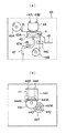
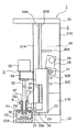
図1(a)は、本発明の第1の実施の形態に係る飲料製造装置の概略構成を示し、この飲料製造装置は、コーヒー豆の挽き豆を湯で抽出することにより得られるコーヒー飲料をカップ式飲料として供給するコーヒーディスペンサであり、カップトレイ3と、カップトレイ3上に配置されてコーヒー飲料を受容するカップ4と、カップ4に受容されたコーヒー飲料および補助原料をカップ内で粉砕、混合、および攪拌するカッティング部5と、カッティング部5を支柱24Aおよび24Bに沿って昇降させる昇降機構部23と、昇降機構部23の背面に設けられてピニオンギヤ27から伝達される回転力を往復方向の駆動力に変換するラック部25と、カッティング部5の蓋部55に配管42Aを介して接続される負圧発生部40と、カッティング部5の蓋部55に配管47を介して接続されるコーヒー抽出器43によって構成されている。
【0017】
カッティング部5は、電力の供給に基づいて回転する駆動モータ50と、駆動モータ50の回転軸に接続されるシャフト52と、シャフト52の先端に取り付けられてシャフト52の回転に基づいてコーヒー飲料および補助原料の混合,攪拌を行う金属材料からなるカッター53と、駆動モータ50を昇降機構部23に着脱自在に支持する駆動モータ支持部54と、樹脂材料で形成されてシャフト52の長さ方向に移動可能に設けられる蓋部55と、蓋部55を着脱自在に支持するとともに昇降機構部23と協働して支柱24Aおよび24Bの長さ方向に移動可能に支持される蓋部支持部材56を有し、蓋部55には、配管47を接続する接続部550と、配管42Aを接続する接続部551と、配管9を接続するための接続部55aが設けられている。また、昇降機構部23と蓋部支持部材56との間の支柱24Aには、蓋部支持部材56を図1(a)における下方に付勢する弾性力を付与するスプリング57が同軸的に設けられている。
【0018】
カッター53は、金属材料で形成されて液体の混合および固形物の粉砕も可能な形状となるように曲げ加工された刃であり、シャフト52の先端に着脱自在に取付けられている。このカッター53は、飲料の種類に応じて、更には、カップ4のサイズや形状に合わせて最適な形状のものを用いることができ、例えば、複数の刃を持ったプロペラ状のものを使用することができる。
【0019】
負圧発生部40は、配管42Aを介してカップ4の内部および配管47を減圧することにより、コーヒー飲料を配管47に送出する供給圧としての負圧を生じさせるものであり、図示しないモータによって駆動される真空ポンプ41と、真空ポンプ41の上流側に設けられて吸引される空気に含まれる液体分を分離するトラップ42と、トラップ42で気液分離された液体分を図示しない廃液バケツに排出させる廃液管42Bを有する。
【0020】
コーヒー抽出器43は、抽出原料としてのコーヒー豆を予め定めた粒度に粉砕して形成される挽き豆を使用し、これを湯に曝すことにより抽出されるコーヒー飲料を負圧に基づいてフィルタでろ過するものであり、後述する昇降機構に基づいて移動可能に設けられるシリンダ44と、シリンダ44に密着してコーヒー抽出部を形成するチャンバー部45と、シリンダ44とチャンバー部45によって挟持されてコーヒー抽出部に受容された湯と挽き豆の混合体をろ過するペーパーフィルタ46と、未使用のペーパーフィルタ46からなるペーパーロール46Aと、使用後のペーパーフィルタ46を巻き取って形成されるペーパーロール46Bと、ペーパーフィルタ46を搬送させる搬送ローラー46Cと、コーヒー抽出部からコーヒー液を送出させるフッ素樹脂チューブ等の弾性材料によって形成される配管47と、モータによって駆動されるカムおよびカムの偏心量に基づいて配管47を変形させる閉止部材を有し、配管47を押圧して弾性変形させることにより閉止するコック部47Aと、コーヒー抽出後の抽出滓を受容する滓受けバケツ48を有する。
【0021】
また、コーヒー抽出器43は、図示しない構成として、コーヒー飲料に応じた粗さの挽き豆を形成してシリンダ44に供給する挽き豆供給部と、高温の湯をシリンダ44に供給する給湯部を有している。
【0022】
図1(b)は、蓋部55の断面を示し、中央にシャフト52を貫通させるための空洞部が形成されており、接続部550から蓋部55の下部端面にかけて形成される流路550Aと、流路550Aの送出側に設けられるノズル553と、接続部551から蓋部55の下部端面にかけて形成される流路55bと、流路55bの吸入側に設けられるパイプ部554を有し、パイプ部554は、蓋部55の表面に付着した液体が流路55bに吸引されることのない突出長をもって設けられている。流路550Aは、蓋部55の上部側面に形成される洗浄水供給用の接続部55aとも接続されている。このことによりカップ4内への飲料吸引、および配管9を介して供給される洗浄水の供給に使用される。配管9は、洗浄水の逆流を防ぐ図示しない電磁弁が装着されて洗浄水供給部(後述)に接続される。また、蓋部55の上部端面には、空洞部とシャフト52との気密漏れを防ぐシールリング552が設けられている。
【0023】
また、蓋部55は、カップに内接する外径を有して形成されており、カップ内壁との接触性を高めるためにカップ接触部分がテーパー状に形成されている。また、飲料の付着を抑制するために表面にフッ素コーティングが施されている。
【0024】
図2は、コーヒー抽出器43を部分的に示し、ペーパーフィルタ46は、(a)に示すように2つのロールRによってチャンバー部45に設けられるチャンバー45Aとシリンダ44との間に配置される。チャンバー45Aは、上部が変形V字型に形成されている。シリンダ44は、図示されるガイド溝44Aおよび44Bに沿って昇降可能に形成されており、チャンバー45Aの上部と密着可能な逆三角形状に形成されている。また、背面に昇降機構が設けられている。同図においてはコック部47Aが配管47を塞いだ状態を示しており、この状態ではコック部47Aの下流にコーヒー液が送出されない状態となる。
【0025】
図2(b)は、シリンダ44の昇降機構をシリンダ44の背面側より示し、コーヒー抽出器43の背面には、シリンダ44を支持するベース440と、ベース440を昇降させる駆動力を発生させる昇降モータ441と、昇降モータ441の回転軸に取り付けられる駆動ギヤ442と、昇降モータ441の回転軸の回転量を検出する切り欠き状の検出部443Aを有する回転量検出板443と、駆動ギヤ442と噛合して回転するギヤ444を有し、ギヤ444にはベース440と係合する係合突起444Aが形成されており、係合突起444Aはベース440に形成されたガイド溝440Aに収容されている。
【0026】
検出部443Aは、一対の発光素子および受光素子からなる図示しない光学センサによって検出される。検出部443Aでは発光素子から受光素子に光が入射し、それ以外の部分では遮光されることによって出力パルスを生じることから、パルスカウント値に基づいてギヤ444の回転量を知ることができる。
【0027】
図2(b)において、ギヤ444は、昇降モータ441の反時計方向の回転に基づいて時計方向に回転し、そのことによって係合突起444Aがガイド溝440A内で右方向に移動することによってベース440を上昇させる。また、昇降モータ441の時計方向の回転に基づいて反時計方向に回転し、そのことによって係合突起444Aがガイド溝440A内で左方向に移動することによってベース440を下降させる。
【0028】
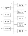
図3は、飲料製造装置の制御ブロックを示し、販売飲料に応じたサイズのカップ4をカップトレイ3に供給するカップディスペンサ6と、カップ4に製氷された氷を供給する製氷部7と、カップ4に砂糖、クリーム等の補助原料を供給する補助原料供給部8と、配管9およびカッティング部5の一部を介して洗浄水を供給する洗浄水供給部10と、各部に設けられるモータ、電磁弁に電力を供給する駆動部11と、オペレータが入力する販売要求に応じた販売要求信号を入力する販売要求信号入力部12と、販売要求信号入力部12から入力する販売要求信号に基づいて各部を制御する制御部13ををバス14で接続している。
【0029】
補助原料供給部8は、粉末あるいは固形状の補助原料をオーガ等の送り出し分材によって供給する供給器と、供給器から供給される補助原料を受容して少量の湯で溶解する溶解器を有しており、溶解器で溶解した補助原料液がカップ4に供給される。
【0030】
制御部13は、カップ3のサイズ(大、中、小)に応じた昇降機構部23の垂直移動量、速度を変更可能に設けられるカッター53の回転速度のデータ、飲料製造時における昇降機構部23の昇降駆動パターン等のプログラムを格納する記憶部と、前述のデータおよびプログラムを手操作等によって変更可能なコントローラ(いずれも図示せず)を有している。
【0031】
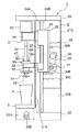
図4は、カッティング部5を含む飲料製造部1の側面部を開放して示し、本体2は、上部20、前面部21A、側面部21B、背面部21C、および基部22によって構成されており、上部20および基部22は、昇降機構部23を垂直方向に移動可能に支持する2本の支柱24Aおよび24Bを支持している。基部22は、カップトレイ3を介して落下した液体を受容するドリップトレイ22Aを収容しており、ドリップトレイ22Aは、受容した廃液等の液体を外部に排出する排出口22Bを有し、排出口22Bは図示しない電磁弁等によって開閉を制御される。
【0032】
昇降機構部23は、背面部にラック部25を有し、ラック部25には駆動モータ26を駆動することにより回転するピニオンギヤ27が噛合している。ピニオンギヤ27は、駆動モータ26の回転トルクを所定の減速比に減速して伝達する減速機28とともに支持部29に固定されており、側面部21Bは、ラック部25とピニオンギヤ27とが所定の噛み合い状態となるように支持部29を固定している。
【0033】
支持部29は、昇降機構部23の所定の位置を検出する一対の発光素子および受光素子からなる光学センサ等の垂直位置検出センサ30A,30B、および30Cを有する。垂直位置検出センサ30Aは、昇降機構部23の上限位置を検出し、垂直位置検出センサ30Bは、昇降機構部23の下限位置を検出し、垂直位置検出センサ30Cは、カッター53の洗浄位置を検出する。昇降機構部23の下限位置は、カップトレイ3にカップ4を配置したときに後述するカッターがカップ4の底部に接触することのない深さ位置である。
【0034】
昇降機構部23は、駆動部11から飲料製造動作に応じて供給される電力に基づいてカッティング部5を昇降させる。また、昇降機構部23は、カッティング部5の先端に付着した汚れを洗浄する洗浄動作においても駆動部11から供給される電力に基づいて洗浄位置に応じた位置にカッティング部5を移動させる。
【0035】
カップトレイ3は、本体2に着脱自在に設けられており、カップ4よりこぼれた飲料等の液体を下方に設けられるドリップトレイ(図示せず)で受容するように格子状に形成されている。
【0036】
図5は、飲料製造部1を背面方向より示し、昇降機構部23は、垂直位置検出センサを遮光するための検出突起23Aを有し、昇降機構部23が支柱24Aおよび24Bに沿って移動すると、その垂直位置に応じて垂直位置検出センサ30A,30B、および30Cの光路を遮るように構成されている。垂直位置検出センサ30A,30B、および30Cは、検出突起23Aによって遮光されるとOFFとなり、制御部13は、垂直位置検出センサのOFFに基づいて駆動モータ26の通電を停止する。前面部21Aには、駆動モータ支持部54および蓋部支持部材56(図示せず)を通過させるための開口部21Dが形成されている。駆動モータ26は、駆動軸の回転量に応じた出力パルスを発生するエンコーダ26Aを備えている。
【0037】
制御部13は、飲料製造部1の電源投入時に駆動モータ26を駆動して昇降機構部23を上限位置へ移動させる。昇降機構部23が上限位置に達すると、垂直位置検出センサ30Aが検出突起23Aによって遮光されてOFFとなり、制御部13は、駆動モータ26の通電停止信号を駆動部11に出力する。駆動部11は、駆動モータ26への通電を停止し、そのことによって駆動モータ26が停止する。制御部13は、駆動モータ26の回転に伴ってエンコーダ26Aから入力した出力パルスをリセットして販売待機状態となる。
【0038】
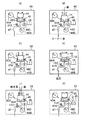
図6(a)から(f)は、コーヒー抽出器43の各部の動作を示す。
図6(a)は、販売待機状態を示し、シリンダ44は上限位置に配置されており、ペーパーフィルタ46は未使用部分がチャンバー部45Aに位置するように設けられる。コック部47Aは配管47を開放している。
【0039】
図6(b)は、シリンダ44の下降動作を示し、コーヒー飲料の販売要求信号が入力されると、シリンダ44が矢印方向に下降してペーパーフィルタ46を間に挟んだ状態でチャンバー45A上に密着する。このことによりコーヒー抽出部が形成される。
【0040】
図6(c)は、原料の供給動作を示し、コーヒー抽出部が形成されると、コック部47Aが回転して配管47を閉止する。次に、シリンダ44に挽き豆供給部から挽き豆が供給される。続いて、シリンダ44に給湯部から高温の湯が供給される。ここで供給される湯量は、挽き豆に水分が浸透する程度の量であり、予め定めた湯量が供給されると湯の供給が停止される。
【0041】
図6(d)は、コーヒー液の送出動作を示し、コック部47Aを回転させて配管47を開き、コーヒー抽出部内に受容された挽き豆と湯の混合体を配管47に作用する負圧に基づいて吸引する。このことによりコーヒー抽出部内でペーパーフィルタ46によりろ過されたコーヒー液が配管47を介して矢印方向に送出する。配管47が開かれると、給湯部はコーヒー抽出部に湯を断続的に供給することにより、適量の湯によってコーヒー抽出が進行するように抽出動作を実行させる。
【0042】
図6(e)は、シリンダ44の上昇動作を示し、配管47に負圧が作用している状態でシリンダ44を矢印方向に上昇させる。チャンバー45Aは、負圧に基づいてペーパーフィルタ46に挽き豆の抽出滓を吸着させており、このことによってシリンダ44と抽出滓との分離を速やかに行わせる。
【0043】
図6(f)は、抽出滓の廃棄動作を示し、配管47の負圧を開放して搬送ローラー46Cを駆動してチャンバー部45から使用済みのペーパーフィルタ46を抽出滓とともに除去する。抽出滓はペーパーフィルタ46の移動に基づいて隣接する滓受けバケツ48に排出される。使用後のペーパーフィルタ46はペーパーロール46Bに巻き取られる。
【0044】
次に、本発明の飲料製造装置によるコーヒー飲料(ホット飲料)の供給動作について、先に説明した各図面を参照しつつ説明する。
【0045】
図7(a)から(d)は、カップ4における飲料の製造工程を示す。なお、図7においては説明を容易にするために動作に係る部分以外の図示を簡略化している。
【0046】
図7(a)において、オペレータが販売要求信号入力部12を操作することにより、制御部13にコーヒー飲料の販売要求信号が入力する。制御部13は、販売要求のあったコーヒー飲料が砂糖、クリーム等の補助原料を含むものであるとき、補助原料供給部8に制御信号を出力する。補助原料供給部8は、コーヒー飲料の種類に応じた補助原料液(同図においては湯で溶解した砂糖液およびクリーム液)を予めカップ4に供給する。
【0047】
また、制御部13は、販売要求信号の入力に基づいてコーヒー抽出器43のコック部47Aを駆動して配管47を閉止し、コーヒー飲料の抽出動作を実行させる。コーヒー抽出器43は、給湯部からコーヒー抽出部に断続的に供給される湯によって挽き豆と湯の接触状態が一定かつ適切な状態となるように管理される。
【0048】
図7(b)は、蓋部55でカップ4を封止した状態を示し、制御部13は、補助原料液の供給後、一定時間が経過すると駆動部11に通電開始信号を出力する。駆動部11は、通電開始信号に基づいて駆動モータ26に通電することにより、図7(a)に示す販売待機位置から昇降機構部23をカップ4のある位置へ下降させる。蓋部支持部材56は、昇降機構部23が下降すると、スプリング57によって下方への弾性力を受ける。このことにより昇降機構部23とともに下降する。蓋部55は、蓋部支持部材56の下降に基づいてカップ4に内接すると、スプリング57の弾性力に基づいてカップ4の内壁面に密接し、そのことによってカップ4が動かないように保持するとともに、カッター53の回転中心とカップの中心軸が一致するようにカップ4の中心位置決めを行う。
【0049】
図7(c)は、カップ4へのコーヒー飲料供給状態を示し、制御部13は、垂直位置検出センサ30Bの検出信号を入力してから一定時間の経過後に負圧発生部40に設けられる真空ポンプ41の駆動命令を駆動部11に出力する。駆動部11は、駆動命令に基づいて真空ポンプ41のモータに通電することにより真空ポンプ41を駆動する。制御部13は、真空ポンプ41を駆動してから一定時間経過後にコック部47Aの駆動命令を駆動部11に出力する。駆動部11は、駆動命令に基づいてコック部47Aのモータに通電することによりカムを回転させて配管47を開放する。コック部47Aの開放によってカップ4および配管47が減圧されて負圧が生じる。蓋部55で封止されたカップ4にはコーヒー抽出器43から負圧に基づいて吸引されたコーヒー飲料が満たされる。トラップ42は、カップ4へのコーヒー飲料の吸引に際し、配管42Aを介してカップ4から空気とともに吸引される水蒸気を気液分離して空気のみを真空ポンプ41を介して大気放出させる。また、気液分離された液体分は廃液管42Bを介して廃液バケツに排出させる。
【0050】
制御部13は、真空ポンプ41の駆動開始から一定時間の経過後に駆動モータ50の駆動命令を駆動部11に出力する。駆動部11は、駆動命令に基づいて駆動モータ50に通電することにより駆動モータ50を駆動する。カップ4内では、カッティング部5のシャフト52を介して駆動されるカッター53によってコーヒー飲料と補助原料液が混合される。また、駆動部11は、昇降機構部23の駆動モータ26に飲料に応じた通電パターンで通電することにより、昇降機構部23を支柱24Aおよび24Bに沿って所定の回数で往復移動させる。カッター53は、昇降機構部23の往復運動に基づいてコーヒー飲料をカップ4の深さ方向に攪拌する。蓋部55は、カッター53の回転に伴ってカップ周縁部に集中する原料がカップ4の外に漏れ出すことを防止する。
【0051】
図7(d)は、コーヒー飲料の供給完了状態を示し、制御部13は、カップ4におけるコーヒー飲料の攪拌を終えると、昇降機構部23の駆動命令を駆動部11に出力する。駆動部11は、駆動信号に基づいて昇降機構部23の駆動モータ26に通電することにより、昇降機構部23が販売待機位置の方向に移動するようにピニオンギヤ27を回転させる。昇降機構部23が上限位置に達すると、垂直位置検出センサ30Aが検出突起23Aによって遮光されてOFFとなり、制御部13は、駆動モータ26の通電停止信号を駆動部11に出力する。駆動部11は、駆動モータ26への通電を停止し、そのことによって駆動モータ26が停止する。制御部13は、駆動モータ26の回転に伴ってエンコーダ26Aから入力した出力パルスをリセットして販売待機状態となる。このようにして製造されたコーヒー飲料を顧客に提供する。
【0052】
図8は、コーヒー飲料製造後の洗浄動作を示し、説明を容易にするためにドリップトレイ22Aを切断して示す。以下、ドリップトレイ22Aを洗浄槽として使用する洗浄動作を説明する。ドリップトレイ22A内の廃液を排出口22Bを介して排出した後に排出口22Bを閉じ、カップトレイ3を取り外してドリップトレイ22Aに洗浄水供給部10から配管9を介して洗浄水Wを満たす。この洗浄水Wを満たしたドリップトレイ22Aにカッター53および蓋部55を浸漬することによって付着した原料を洗い流す。
【0053】
制御部13は、コントローラから洗浄命令を入力すると、駆動部11に通電開始信号を出力する。駆動部11は、通電開始信号に基づいて駆動モータ26に通電することにより、昇降機構部23を洗浄位置まで下降させる。昇降機構部23が洗浄位置に達すると、垂直位置検出センサ30Cが検出突起23Aによって遮光されてOFFとなり、制御部13は、駆動モータ26の通電停止信号を駆動部11に出力する。駆動部11は、駆動モータ26への通電を停止し、そのことによって駆動モータ26が停止する。このとき、カッター53および蓋部55はドリップトレイ22Aの内部に配置される。
【0054】
次に、制御部13は、洗浄水供給部10に洗浄水供給信号を出力する。洗浄水供給部10は、洗浄水供給信号に基づいて配管9に洗浄水Wを送出する。洗浄水Wは、配管9から流路550Aを介してドリップトレイ22Aの内部に供給される。制御部13は、一定時間の経過後に洗浄水供給部10に洗浄水停止信号を出力する。洗浄水供給部10は、洗浄水停止信号に洗浄水Wの送出を停止する。続いて、制御部13は、駆動部11に通電開始信号を出力する。駆動部11は、通電開始信号に基づいて駆動モータ50に通電することによりカッター53を低速で回転させる。このことによってドリップトレイ22A内の洗浄水Wが攪拌され、洗浄水に浸漬されているカッター53および蓋部55を洗浄する。
【0055】
制御部13は、一定時間の経過後に駆動部11に通電停止信号を出力する。駆動部11は、通電停止信号に基づいて駆動モータ50への通電を停止する。このことにより駆動モータ50が停止する。制御部13は、排出口22Bの電磁弁を開放して洗浄水Wを排出させる。また、駆動部11に通電開始信号を出力して駆動モータ26に電力を供給させる。駆動モータ26は、通電に基づいて昇降機構部23を上昇させる。昇降機構部23が上限位置に達すると、垂直位置検出センサ30Aが検出突起23Aによって遮光されてOFFとなり、制御部13は、駆動モータ26の通電停止信号を駆動部11に出力する。駆動部11は、駆動モータ26への通電を停止し、そのことによって駆動モータ26が停止する。制御部13は、駆動モータ26の回転に伴ってエンコーダ26Aから入力した出力パルスをリセットして販売待機状態となる。
【0056】
上記した洗浄動作においては、操作者が事前にカップトレイ3を取り外す作業が必要となるが、例えば、カップトレイ3を機械的に収納可能なシャッター機構等によって構成し、飲料製造後にカップトレイ3を収容して洗浄工程を行った後に洗浄水Wを排水し、昇降機構部23を販売待機位置に戻し、収容していたカップトレイ3を収容前の状態に復元させるようにしても良い。また、飲料製造動作に連続して洗浄動作を行わせる以外に、必要に応じて洗浄動作のみを実行させることもできる。
【0057】
図9は、カップ4を洗浄槽として用いる他の洗浄動作を示し、説明を容易にするためにカップ4を切断して図示している。カップディスペンサ6からカップトレイ3にカップ4を供給し、昇降機構部23を下降させて蓋部55で開口部を封止した状態で配管9および流路550Aを介してカップ4内に洗浄水Wを供給する。次に、駆動モータ50を駆動してカッター53を回転させることにより、洗浄水Wを攪拌してカッター53および蓋部55のカップ内部側を洗浄するようにしても良い。洗浄工程の終了後は、昇降機構部23を販売待機位置に移動させるとともに洗浄水Wの満たされたカップ4をカップトレイ3から取り除く。
【0058】
上記した第1の実施の形態によると、配管42Aおよび配管47を接続される蓋部55でカップ4から空気や液体が漏れないように気密的に封止するようにしたので、カップ4を含めたこれらの配管を負圧伝達経路および飲料送出経路として共用することができる。このことにより、配管の設置数を低減させて飲料供給系の構成を簡素化することができる。また、コーヒー抽出器43からカップ4へ直にコーヒー飲料を供給でき、かつ、外気に触れないことから香り、味覚を失うことなく速やかに供給できる。
【0059】
また、カップ4を蓋部55で封止しているので、負圧によるコーヒー飲料のカップ吸引時にコーヒー飲料が外部にこぼれることを防止できる。また、蓋部55はカップ4の飲み口より下方に内接するように形成されているので、顧客への提供時に飲み口部分にコーヒー飲料の付着がなく、見た目の良好なカップ式飲料として提供することができる。
【0060】
また、蓋部55をドリップトレイ22A又はカップ4に貯留した洗浄水に浸漬して洗浄可能な構成としているので、付着したコーヒー飲料や補助原料による汚損を抑制して衛生的に維持することができる。
【0061】
蓋部55の表面にフッ素コーティングを施しているので、飲料製造後の洗浄時に蓋部55の洗浄性を向上させることができる。
【0062】
また、カッティング部5とともに昇降可能な蓋部55をシャフト52に同軸的に設けたことによって、カップ4に蓋部55が内接する際にカップ4の中心軸がカッター53の回転軸と一線状になるように位置決めされる。このことによりカッター53の回転時にカップ4が倒れたり不安定になることを防ぐことができるとともに均一な攪拌効果が得られる。
【0063】
蓋部55によるカップ4の封止時に、カッター53の回転中心とカップの中心軸とをずらして配置するようにしても良く、カッター53の回転に基づいてカップ4の内部に発生する渦の形成状態を変化させて異なった攪拌性を付与することもできる。
【0064】
コーヒー抽出器43に設けられるチャンバー45Aの上部を変形V字型に形成したことによって、抽出滓の廃棄時にチャンバー45Aの上部に密着していたペーパーフィルタ46が張架されて抽出滓の分離が促される。このことによりペーパーフィルタ46上の滓残りを低減でき、ペーパーフィルタ搬送系の汚損を低減させることができる。
【0065】
抽出飲料としては、上記したコーヒー飲料の他に紅茶、ウーロン茶、緑茶等のお茶飲料であっても良い。
【0066】
また、コーヒー抽出器以外の他の飲料形成部として、シロップ原料と希釈水あるいは炭酸水を一定の希釈比率で混合することにより飲料を製造するものであっても良く、ホット飲料の他のコールド飲料を供給するものに適用しても良い。
【0067】
また、カップ4にコーヒー飲料を送出させるための供給圧を付与する構成は、上記した負圧発生部40に限定されず、例えば、コーヒー抽出器43のコーヒー抽出部を加圧する加圧器を設け、加圧抽出されたコーヒー飲料を配管47を介して蓋部55で封止されたカップ4に圧送し、カップ4で気液分離された空気を配管42Aを介して大気放出させるようにしても良い。あるいは、配管42Aを加圧器に接続して空気を循環させる構成としても良い。
【0068】
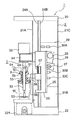
図10は、第2の実施の形態として、カッティング部5にカップ4を封止する二重蓋を設けた飲料製造部1を示し、蓋部55は、カップ4に内接する外径を有して形成された円板状の下蓋55Aと、カップ4の上部を封止する円板状の上蓋55Bと、下蓋55Aに同軸的に設けられて上蓋55Bを図面に示す下方向に押し付けるスプリング55Dを有し、下蓋55Aと上蓋55Bとをシャフト52に同軸的に直列に配置している。下蓋55Aは、カップ4の内壁との接触性を高めるためにカップ接触部分がテーパー状に形成されており、第1の実施の形態において説明したノズルおよびパイプ部(符号省略)が設けられている。上蓋55Bは、下蓋55Aの筒状部分に沿って摺動自在に支持されている。また、下蓋55Aおよび上蓋55Bは、飲料の付着を抑制するために表面にフッ素コーティングが施されている。
【0069】
また、蓋部55は、配管9を接続するための接続部55aが筒状部55Cに形成されている。その他の構成および機能は第1の実施の形態で説明した飲料製造部1と同一であるので重複する説明を省略する。
【0070】
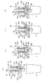
図11(a)から(d)は、蓋部55がカップ4を封止する動作および分離する動作を示し、説明を容易にするために動作に係る部分以外の図示を簡略化している。図11(a)に示すカップ未封状態にあるとき、上蓋55Bはスプリング55Dによって下蓋55A側に押し付けられている。シャフト52は、その先端部に設けられる小径部51に固定ピン51Aを有し、カッター53の固定溝53Aに固定ピン51Aを係止することによってカッター53が回転時に脱落しないように固定している。
【0071】
図11(b)は、蓋部55が下降して上蓋55Bがカップ4の上部に当接した状態を示し、蓋部55が矢印方向に下降すると、まず、下蓋55Aがカップ4内に挿入され、続いて、上蓋55Bがカップ4の上部に当接する。
【0072】
図11(c)は、蓋部55が更に矢印方向に下降して下蓋55Aがカップ4の内壁に当接した状態を示し、下蓋55Aがカップ4の内壁に密接して隙間を封止することにより飲み口側(カップ周縁部)への液漏れを防ぐ。このとき、下蓋55Aはカップ4の中心とカッター53の回転中心が一致するようにカップ4を位置決めする。また、蓋部55の下降によって、スプリング支持部55Eがスプリング55Dを圧縮することにより、上蓋55Bをカップ4の上部に押し付ける。このことによって、カップ4をカップトレイ(図示せず)上に安定的に配置する。
【0073】
図11(d)は、カップ4から蓋部55が分離するときの状態を示し、蓋部55が矢印方向に上昇すると、上蓋55Bはスプリング55Dの弾性力に基づいてカップ4の上部を下方に押し付けていることにより、その反作用によってカップ4に下蓋55Aの分離を促す方向の力を付与する。一方、下蓋55Aは矢印で示す方向に移動することにより、カップ4と下蓋55Aとが分離する。
【0074】
上記した第2の実施の形態によると、下蓋55Aおよび上蓋55Bからなる蓋部55をカッティング部5に設けたことによって、カップ4内へのコーヒー飲料吸引時、および混合,攪拌時に下蓋55Aによってコーヒー飲料が外へ漏れることを防ぐとともに、上蓋55Bによってカップ4が上方から安定的に保持される。また、カップ4と蓋部55とを分離するときは、スプリング55Dの反撥力に基づいて上蓋55Bが下蓋55Aの分離方向と相反する方向にカップ4を押すことにより、下蓋55Aをカップ4から抜け易くするので、カップ4と蓋部55との分離性を向上させることができる。
【0075】
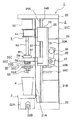
図12は、第3の実施の形態として、カップ4への負圧抽出を可能にする負圧発生部40およびコーヒー抽出器43を設けたカップ式飲料の自動販売機を示し、調理部60は、水平方向に延びる搬送機構61と、カップCを供給するカップ供給装置62と、クリーム、コーヒー、および砂糖等の補助原料(粉末)をカップCに供給する原料貯蔵部63A、63B,および63Cを備えたキャニスタ63と、カップCにレモンシロップ、生クリーム等のシロップをシロップポンプ64Aの送出動作に基づいて送出管64Bから送出するシロップ供給装置64と、カップCに湯を供給する湯タンク65と、粉末原料と湯との攪拌(調理)、氷等の固形分の粉砕を行う回転可能なカッター部66Aおよび蓋部66Bを有する攪拌機構66と、アイス飲料の調理に使用する氷を製氷し、貯水する製氷機67と、コーヒー,紅茶,緑茶等の抽出飲料を製造するコーヒー抽出器43と、蓋部66Bで封止されたカップCの内部を減圧して負圧空間を形成する負圧発生部40を有する。コーヒー抽出器43は、第1の実施の形態で説明したコーヒー抽出器43と同一の構成を有する。
【0076】
搬送機構61は、左右方向(図12に対し)水平に直線的に延びる支持フレーム68、支持フレーム68の両端部にそれぞれ回転自在に軸支された駆動プーリ69Aおよび従動プーリ69B、駆動プーリ69Aおよび従動プーリ69Bの間に掛け渡した無端の搬送ベルト70、駆動プーリ69Aを作動させる搬送モータ71、および、支持フレーム68と平行して設けたサブフレーム72によって構成された主搬送部73と、一端を搬送ベルト70に固定し、他端をサブフレーム72上に載置して設けられ、両端部にそれぞれ回転自在に軸支された駆動プーリ74Aおよび従動プーリ74Bを有する支持フレーム75、駆動プーリ74Aおよび従動プーリ74Bの間に掛け渡した無端の搬送ベルト76、駆動プーリ74Aを作動させる搬送モータ77、搬送ベルト70の作動に伴って支持フレーム75が支持フレーム68面上を転勤するように設けたローラ78、および、サブフレーム72面上を転勤するように設けたローラ79によって構成されたカップ保持機構搬送部80を有し、カップ保持機構搬送部80は、搬送ベルト76に固定されたカップ保持機構81を有している。
【0077】
カップ保持機構搬送部80は、搬送モータ71を回転させて搬送ベルト70を駆動すると、ローラ78が支持フレーム68、ローラ79がサブフレーム72のそれぞれの面上を転動することにより、図示する左右方向に円滑に移動する。
【0078】
カップ保持機構81は、搬送ベルト76の搬送動作に応じて支持フレーム75上を転動できるようにローラ82を有する。搬送モータ77を回転させて搬送ベルト76を駆動すると、ローラ82が支持フレーム75の面上を転動することにより、図示する前後方向に円滑に移動する。
【0079】
搬送モータ71および搬送モータ77は、図示しない制御部から出力される駆動信号に基づいて正転方向又は逆転方向に回転し、そのことによってカップ保持機構81を、同図における前後左右方向へ自在に移動させる。
【0080】
また、カップ保持機構81は、カップ供給装置62から供給されるカップCを受けるカップ受台83と、カップCの胴部を把持するカップ把持アーム84とを有し、カップ受台83は、モーターを駆動源として回転量を往復方向の運動量に変換する図示しないカップ受台昇降機構により、カップCのサイズ(大、中、小)に応じたカップ高さ(上下)方向に移動する。また、カップ把持アーム84は、図示しないアーム開閉機構によってカップCのサイズに応じたアーム間隔に一対のアームを開閉することによりカップ受台83で受けたカップCを把持する。
【0081】
図13(a)および(b)は、攪拌機構66において、カッター66Aに同軸的に設けられる蓋部66Bを示し、この蓋部66Bは、図13(a)に示すように、カッター66Aに同軸的に設けられるスプリング66Cによって、上記したカップ保持機構81に保持されて搬送されたカップCの内壁面に密接するように形成されている。また、蓋部66Bは、コーヒー抽出器43で抽出された抽出飲料を供給する配管47を接続する接続部660と、負圧発生部40に接続される配管42Aを接続する接続部661が設けられている。カップCは、搬送時に接触を防ぐために所定の高さ位置に配置される。カップCに受容されて搬送された原料は、カッター66Aの回転に基づいて粉砕、混合されるとともに、図13(b)に示すように、カップ受台83の上下動作に基づいてカップ内の表面部から底面部にかけての深さ方向に攪拌される。このとき、蓋部66Bは、スプリング66Cの弾性力に基づいてカップCの内壁面に密接し、カップCから原料がこぼれることを防止する。
【0082】
以下に、上記したカップ式飲料の自動販売機で、抽出飲料としてのコーヒー飲料を製造する動作を説明する。
【0083】
顧客によって図示しない飲料選択ボタン(砂糖,クリーム入りコーヒー飲料)が押されると、制御部は、カップ供給装置62にカップ供給動作を実行させる。カップ供給装置62はカップ保持機構81にカップCを供給する。カップ保持機構81は、カップ受台83でカップCを受けるとともにカップ把持アーム84でカップCを保持固定する。次に、制御部は、搬送モータ71と搬送モータ77を駆動してカップ保持機構81を補助原料としての砂糖,クリームの供給位置に順次移動させることにより補助原料がカップCに供給される。
【0084】
次に、制御部は、カップ保持機構81を攪拌機構66のある位置に移動させる。制御部は、カップ受台昇降機構のモータに通電することにより、カップ把持アーム84で把持しているカップCをカップ受台83とともにカッター66Aの方向に上昇させる。蓋部66Bは、カップ受台83の上昇に基づいてカップCと内接し、そのことによってカップCを封止する。負圧発生部40は配管42Aを介してカップCの内部を減圧することにより負圧空間を形成する。コーヒー抽出器43は、負圧発生部40によって生じた負圧に基づいて配管47を介してカップCにコーヒー飲料を送出する。制御部は、攪拌機構66に通電してカッター66Aを回転させるとともに、カップ受台昇降機構のモータに通電してカップ受台83を上下に移動させる。このようにしてカップC内のコーヒー飲料を深さ方向に攪拌する。
【0085】
制御部は、コーヒー飲料の製造工程が終了すると、カップ保持機構搬送部80を駆動してカップ保持機構81を図示しない販売口に移動させる。カップ把持アーム84は、把持しているカップCを販売口で分離する。制御部は、カップ保持機構81を待機位置に移動させる。このようにしてコーヒー飲料を購入客に販売する。
【0086】
上記した第3の実施の形態によると、カッター66Aに対してカップ保持機構81で保持しているカップCを昇降させるようにしたので、カップCを負圧伝達経路および飲料送出経路として用いることができ、機内の収容スペースや配管設置上の制約があるカップ式飲料の自動販売機においても構成を複雑化させることなく、香り、味覚に優れるコーヒー飲料を速やかにカップCに供給することができる。
【0087】
なお、図12に示す構成では、カッター66Aを固定系に設けたものとして説明したが、第1の実施の形態で説明した昇降機構部によって昇降可能な構成としても良く、カップ受台83に載置されたカップCの昇降動作に応じてカッター部66Aを昇降させるようにしても良い。このような構成によると、カップ受台83のみを移動させる構成と比べてカップCの深さ方向への攪拌性を損なうことなくカップ受台83の垂直移動量を半減させることができる。
【0088】
また、カップCを封止する蓋部については、上記した内接型の蓋の他にカップCの上部を覆って封止する外接型の蓋部であっても良い。この場合には、カップCのサイズが複数使用されるカップ式飲料の自動販売機において飲料の種類又は顧客の希望によって販売量が増減する場合であっても対応することが可能になる。
【0089】
図14(a)は、第4の実施の形態として、カッティング部5にカップ4の上部を覆って封止する外接型の蓋部55Fを設けた飲料製造装置の概略構成を示し、蓋部55Fは、カップ4のサイズによって開口径が異なる場合でも封止することができる直径を有して形成されている。その他の構成は第1の実施の形態で説明した飲料製造装置と同一であるので、重複する説明を省略する。
【0090】
図14(b)は、蓋部55Fがカップ4を封止した状態を示す。この状態で配管42Aを介してカップ4の内部および配管47を減圧し、コーヒー抽出器43から配管47を介してコーヒー飲料をカップ4に吸引する。
【0091】
上記した第4の実施の形態によると、カップ4の上部を覆って封止する蓋部55Fを設けたので、蓋部55Fの交換を必要とせずに複数のカップサイズに対応できるとともに、負圧による抽出性を損なうことなくコーヒー、紅茶等の抽出飲料を、例えば、S、M、Lといった顧客の希望する販売量に応じてカップ4に速やかに供給することができる。
【0092】
上記した各実施の形態において、カップを封止する内接型の蓋部については、カップ内壁との接触性を高めるためにカップ接触部分をテーパー状に形成しているが、例えば、フッ素ゴム等の弾性材料で形成された環状のシールリングをカップ接触部分に設けるようにしても良い。また、内接型、外接型ともに蓋部の底部(カップ側)を肉抜きしてカッターを断面内に収容可能な形状とすることで、カッターの露出を防ぐことができ、カッターに不用意に接触することによる事故の発生を防ぐことができる。
【0093】
【発明の効果】
以上説明した通り、本発明の飲料製造装置によると、コーヒー飲料を受容して顧客に提供するためのカップを供給圧伝達経路および飲料送出経路として配管に気密的に接続させるようにしたため、抽出飲料の香り、味覚を損なうことなく速やかにカップに供給することができる。
【図面の簡単な説明】
【図1】(a)は、本発明の第1の実施の形態に係る飲料製造装置の概略構成図
(b)は、蓋部の断面図
【図2】(a)は、コーヒー抽出器の正面図
(b)は、コーヒー抽出器の背面図
【図3】飲料製造装置の制御ブロック図
【図4】飲料製造部の一方を開放した側面図
【図5】飲料製造部の一方を開放した背面図
【図6】(a)から(f)は、コーヒー抽出器の動作説明図
【図7】(a)から(d)は、カップにおけるコーヒー飲料の製造工程を示す動作説明図
【図8】飲料製造部の洗浄工程を示す部分断面図
【図9】飲料製造部の他の洗浄工程を示す部分断面図
【図10】本発明の第2の実施の形態に係る飲料製造装置の概略構成図
【図11】(a)から(d)は、第2の実施の形態における蓋部がカップを封止する動作および分離する動作を示す動作図
【図12】本発明の第3の実施の形態に係るカップ式飲料の自動販売機の概略構成図
【図13】第3の実施の形態に係る攪拌機構の概略構成図
【図14】(a)は、本発明の第4の実施の形態に係る飲料製造装置の概略構成図
(b)は、蓋部の断面図
【図15】従来の飲料製造装置の概略構成図
【符号の説明】
1,飲料製造部 2,本体 3,カップトレイ 4,カップ
5,カッティング部 6,カップディスペンサ 7,製氷部
8,補助原料供給部 9,配管 10,洗浄水供給部 11,駆動部
12,販売要求信号入力部 13,制御部 14,バス 20,上部
21A,前面部 21B,側面部 21C,背面部 21D,開口部
22,基部22A,ドリップトレイ 22B,排出口 23,昇降機構部
23A,検出突起 24A,支柱 25,ラック部26,駆動モータ
26A,エンコーダ 27,ピニオンギヤ 28,減速機
29,支持部 30A,垂直位置検出センサ 30B,垂直位置検出センサ
30C,垂直位置検出センサ
40,負圧発生部 41,真空ポンプ 42,トラップ 42A,配管
42B,廃液管 43,コーヒー抽出器 44,シリンダ 45,チャンバー部
45A,チャンバー 46,ペーパーフィルタ 46A,ペーパーロール
46B,ペーパーロール 46C,搬送ローラー 47,配管
47A,コック部 48,滓受けバケツ 50,駆動モータ 51,小径部
51A,固定ピン 52,シャフト 53,カッター 53A,固定溝
54,駆動モータ支持部55,蓋部 55A,下蓋 55B,上蓋
55a,接続部 55b,流路 55C,筒状部 55D,スプリング
55E,スプリング支持部 55F,蓋部 56,蓋部支持部材
57,スプリング60,調理部 61,搬送機構 62,カップ供給装置
63,キャニスタ 63A,原料貯蔵部 64,シロップ供給装置
64A,シロップポンプ 64B,送出管 65,湯タンク
66,攪拌機構 66A,カッター 66B,蓋部 66C,スプリング
67,製氷機 68,支持フレーム 69A,駆動プーリ 69B,従動プーリ
70,搬送ベルト 71,搬送モータ 72,サブフレーム
73,主搬送部 74A,駆動プーリ 74B,従動プーリ
75,支持フレーム 76,搬送ベルト 77,搬送モータ
78,ローラ 79,ローラ 80,カップ保持機構搬送部
81,カップ保持機構 82,ローラ 83,カップ受台
84,カップ把持アーム 90,コーヒー抽出器 90A,配管
91,コーヒー飲料 92,貯留タンク 92A,配管 92B,ノズル
93,カップ 94,空気ライン 95,真空ポンプ
96,エアコンプレッサ 97,エアバルブ 98,エアバルブ
550,接続部 550A,流路 551,接続部 552,シールリング
553,ノズル 554,パイプ部 660,接続部 661,接続部[0001]
BACKGROUND OF THE INVENTION
The present invention relates to a beverage production apparatus, and more particularly to a beverage production apparatus for producing a cup-type beverage.
[0002]
[Prior art]
2. Description of the Related Art Conventionally, a coffee supply device that provides a coffee beverage as a cup-type beverage is known. In particular, a coffee extraction beverage (hereinafter referred to as a coffee beverage) is obtained by extracting ground beans obtained by grinding coffee beans to a predetermined particle size with hot water. ) For producing beverages such as cup-type vending machines and coffee dispensers.
[0003]
In such a beverage manufacturing apparatus, since it is mainly used for business, there is a limitation in the time until a coffee beverage is provided to a customer in response to a sales request. For this reason, as what implement | achieves quick coffee extraction, there exists what extracts a coffee drink by forcibly filtering the mixture of ground beans and hot water with a filter.
[0004]
An example of a beverage production apparatus that extracts a coffee beverage based on forced filtration is disclosed in Japanese Patent Application Laid-Open No. 11-221155.
[0005]
FIG. 15 shows a schematic configuration of a beverage manufacturing apparatus disclosed in JP-A-11-221155, a
[0006]
This beverage production apparatus opens the
[0007]
According to such a structure, it can be set as a simple structure compared with the structure which provides a pump in piping which conveys a coffee drink, and conveys coffee.
[0008]
[Problems to be solved by the invention]
However, according to the conventional beverage manufacturing apparatus, since the extracted coffee beverage is temporarily stored and then supplied to the cup, there is a problem in that component parts such as a storage portion are required and the apparatus cost increases. Moreover, in the structure which stores a coffee drink, the extracted drink excellent in the freshly extracted fragrance and taste cannot be rapidly supplied to a cup.
[0009]
Therefore, the objective of this invention is providing the drink manufacturing apparatus which can be rapidly supplied to a cup, without impairing the fragrance and taste of an extracted drink.
[0010]
[Means for Solving the Problems]
In order to achieve the above-described object, the present invention provides a beverage forming part for forming a beverage, When the cup that provides the beverage to the customer, the lid mechanism is provided so as to be movable relative to the cup by an elevating mechanism, and the cup is hermetically sealed by the lid, When the cup is hermetically sealed by a beverage supply pipe that is airtightly connected to the space in the cup and supplies the beverage from the beverage forming portion to the cup, and the lid portion, the space in the cup A negative pressure generating unit that is airtightly connected and generates a negative pressure in the cup and the beverage supply pipe, and a controller that controls the beverage forming unit, the elevating mechanism, and the negative pressure generating unit, When there is a sales request, the control unit causes the beverage forming unit to form the beverage and controls the lifting mechanism to hermetically seal the cup with the lid, and then the negative pressure generating unit. Control Causing a negative pressure inside and the beverage supply pipeline the cup, to supply the beverage to the cup on the basis of the negative pressure A beverage production apparatus is provided.
[0014]
According to the beverage manufacturing apparatus described above, the pipe line can be used as the supply pressure transmission path and the beverage delivery path by airtightly connecting containers for receiving beverages and providing them to customers. The beverage delivered from the beverage forming part via the conduit based on the supply pressure is gas-liquid separated in the container.
[0015]
DETAILED DESCRIPTION OF THE INVENTION
Hereinafter, embodiments of the present invention will be described in detail with reference to the drawings.
[0016]
Fig.1 (a) shows schematic structure of the drink manufacturing apparatus based on the 1st Embodiment of this invention, This drink manufacturing apparatus is a coffee drink obtained by extracting the ground coffee beans with hot water. It is a coffee dispenser to be supplied as a cup-type beverage, and a
[0017]
The
[0018]
The
[0019]
The negative
[0020]
The
[0021]
In addition, the
[0022]
FIG. 1B shows a cross section of the
[0023]
The
[0024]
FIG. 2 partially shows the
[0025]
FIG. 2B shows the lifting mechanism of the
[0026]
The
[0027]
In FIG. 2 (b), the
[0028]
FIG. 3 shows a control block of the beverage manufacturing apparatus, a cup dispenser 6 for supplying a
[0029]
The auxiliary raw material supply unit 8 has a feeder that supplies powder or solid auxiliary raw material by a feed material such as an auger, and a dissolver that receives the auxiliary raw material supplied from the supplier and dissolves it with a small amount of hot water. The auxiliary raw material solution dissolved in the dissolver is supplied to the
[0030]
The
[0031]
FIG. 4 shows an open side of the
[0032]
The elevating
[0033]
The
[0034]
The raising /
[0035]
The
[0036]
FIG. 5 shows the
[0037]
The
[0038]
FIGS. 6A to 6F show the operation of each part of the
FIG. 6A shows a sales standby state, the
[0039]
FIG. 6B shows the lowering operation of the
[0040]
FIG. 6C shows the raw material supply operation. When the coffee extraction unit is formed, the
[0041]
FIG. 6 (d) shows the coffee liquid delivery operation. The
[0042]
FIG. 6 (e) shows the raising operation of the
[0043]
FIG. 6 (f) shows the disposal operation of the extraction soot, releasing the negative pressure of the
[0044]
Next, the supply operation of the coffee beverage (hot beverage) by the beverage production apparatus of the present invention will be described with reference to the drawings described above.
[0045]
FIGS. 7A to 7D show a process for producing a beverage in the
[0046]
In FIG. 7A, when the operator operates the sales request
[0047]
Moreover, the
[0048]
FIG. 7B shows a state in which the
[0049]
FIG.7 (c) shows the coffee drink supply state to the
[0050]
The
[0051]
FIG. 7 (d) shows a coffee beverage supply completion state, and when the
[0052]
FIG. 8 shows the washing operation after the coffee beverage is produced, and shows the
[0053]
When the
[0054]
Next, the
[0055]
The
[0056]
In the above-described cleaning operation, the operator needs to remove the
[0057]
FIG. 9 shows another cleaning operation using the
[0058]
According to the first embodiment described above, the
[0059]
Moreover, since the
[0060]
Moreover, since it is set as the structure which can be wash | cleaned by immersing the
[0061]
Since the surface of the
[0062]
Further, the
[0063]
When the
[0064]
By forming the upper part of the
[0065]
As the extracted beverage, tea beverages such as black tea, oolong tea and green tea may be used in addition to the coffee beverage described above.
[0066]
Further, as a beverage forming part other than the coffee extractor, a beverage may be produced by mixing a syrup raw material and diluted water or carbonated water at a certain dilution ratio, and other cold beverages other than hot beverages You may apply to what supplies.
[0067]
Moreover, the structure which provides the supply pressure for sending a coffee drink to the
[0068]
FIG. 10 shows the
[0069]
Moreover, the
[0070]
FIGS. 11A to 11D show the operation of sealing and separating the
[0071]
FIG. 11B shows a state in which the
[0072]
FIG. 11C shows a state in which the
[0073]
FIG. 11D shows a state when the
[0074]
According to the second embodiment described above, by providing the cutting
[0075]
FIG. 12 shows a cup-type beverage vending machine provided with a
[0076]
The
[0077]
When the
[0078]
The
[0079]
The
[0080]
The
[0081]
FIGS. 13A and 13B show a
[0082]
Below, the operation | movement which manufactures the coffee drink as an extracted drink with the above-mentioned cup-type drink vending machine is demonstrated.
[0083]
When a beverage selection button (sugar, creamed coffee beverage) (not shown) is pressed by the customer, the control unit causes the
[0084]
Next, the control unit moves the
[0085]
When the coffee beverage manufacturing process is completed, the control unit drives the cup holding
[0086]
According to the third embodiment described above, since the cup C held by the
[0087]
In the configuration shown in FIG. 12, the
[0088]
The lid for sealing the cup C may be a circumscribed lid that covers and seals the upper portion of the cup C in addition to the inscribed lid described above. In this case, in a cup-type beverage vending machine in which a plurality of sizes of cups C are used, it is possible to cope with a case where the sales amount increases or decreases depending on the type of beverage or the desire of the customer.
[0089]
FIG. 14A shows a schematic configuration of a beverage production apparatus in which a
[0090]
FIG. 14B shows a state where the
[0091]
According to the fourth embodiment described above, since the
[0092]
In each of the above-described embodiments, the inscribed lid for sealing the cup has a cup contact portion formed in a tapered shape in order to improve the contact with the inner wall of the cup. An annular seal ring made of the elastic material may be provided at the cup contact portion. In addition, by making the bottom part (cup side) of the lid part thin so that the cutter can be accommodated in the cross section for both the inscribed type and the circumscribed type, exposure of the cutter can be prevented, and the cutter is inadvertent Accidents caused by contact can be prevented.
[0093]
【The invention's effect】
As described above, according to the beverage production apparatus of the present invention, the cup for receiving the coffee beverage and providing it to the customer is hermetically connected to the pipe as the supply pressure transmission path and the beverage delivery path. Can be quickly supplied to the cup without impairing the scent and taste.
[Brief description of the drawings]
FIG. 1A is a schematic configuration diagram of a beverage production apparatus according to a first embodiment of the present invention.
(B) is a sectional view of the lid
FIG. 2A is a front view of a coffee extractor.
(B) is a rear view of the coffee extractor
FIG. 3 is a control block diagram of the beverage manufacturing apparatus.
FIG. 4 is a side view of one of the beverage production departments opened.
FIG. 5 is a rear view with one side of the beverage production department opened.
FIGS. 6A to 6F are diagrams for explaining the operation of the coffee extractor.
FIGS. 7A to 7D are operation explanatory views showing a process for producing a coffee beverage in a cup.
FIG. 8 is a partial cross-sectional view showing the washing process of the beverage production department
FIG. 9 is a partial cross-sectional view showing another cleaning process of the beverage production department
FIG. 10 is a schematic configuration diagram of a beverage production apparatus according to a second embodiment of the present invention.
FIGS. 11A to 11D are operation diagrams showing the operation of the lid portion sealing and separating the cup in the second embodiment;
FIG. 12 is a schematic configuration diagram of a cup-type beverage vending machine according to a third embodiment of the present invention.
FIG. 13 is a schematic configuration diagram of a stirring mechanism according to a third embodiment.
FIG. 14 (a) is a schematic configuration diagram of a beverage manufacturing apparatus according to a fourth embodiment of the present invention.
(B) is a sectional view of the lid
FIG. 15 is a schematic configuration diagram of a conventional beverage manufacturing apparatus.
[Explanation of symbols]
1,
5, cutting part 6, cup dispenser 7, ice making part
8, Auxiliary
12, sales request
21A,
22,
23A,
26A,
29,
30C, vertical position detection sensor
40, negative
42B,
45A,
46B,
47A,
51A, fixing
54, drive
55a,
55E,
57,
63,
64A,
66, stirring
67,
70,
73,
75,
78,
81,
84,
91,
93,
96,
550,
553,
Claims (8)
前記飲料を顧客に提供するカップと、
昇降機構によって前記カップに対して相対移動可能に設けられ、前記カップを気密封止する蓋部と、
前記蓋部によって前記カップが気密封止されたとき、前記カップ内の空間に気密的に接続され、前記飲料形成部から前記カップへ前記飲料を供給する飲料供給配管と、
前記蓋部によって前記カップが気密封止されたとき、前記カップ内の空間に気密的に接続され、前記カップ内及び前記飲料供給配管に負圧を発生させる負圧発生部と、
前記飲料形成部、前記昇降機構、及び前記負圧発生部を制御する制御部とを備え、
前記制御部は、販売要求があると、前記飲料形成部に前記飲料の形成を行わせると共に、前記昇降機構を制御して前記蓋部によって前記カップを気密封止した後、前記負圧発生部を制御して前記カップ内及び前記飲料供給配管に負圧を生じさせ、当該負圧に基づいて前記飲料を前記カップに供給することを特徴とする飲料製造装置。A beverage forming part for forming a beverage;
A cup for providing the beverage to a customer;
A lid that is provided so as to be relatively movable with respect to the cup by an elevating mechanism, and hermetically seals the cup;
When the cup is hermetically sealed by the lid, a beverage supply pipe that is hermetically connected to the space in the cup and supplies the beverage from the beverage forming unit to the cup;
When the cup is hermetically sealed by the lid, a negative pressure generator that is hermetically connected to the space in the cup and generates negative pressure in the cup and the beverage supply pipe;
A controller for controlling the beverage forming part, the elevating mechanism, and the negative pressure generating part,
When there is a sales request, the control unit causes the beverage forming unit to form the beverage, and controls the lifting mechanism to hermetically seal the cup with the lid, and then the negative pressure generating unit. control to cause negative pressure in and the beverage supply pipeline the cup, beverage production device characterized that you supplying the beverage to the cup on the basis of the negative pressure.
前記カップに外接する第2の蓋によって構成されることを特徴とする請求項第1項記載の飲料製造装置。 The lid portion includes a first lid inscribed in the cup;
Beverage production device as set forth in claim 1, wherein claims, characterized in that constituted by a second cover circumscribing the said cup.
Priority Applications (1)
| Application Number | Priority Date | Filing Date | Title |
|---|---|---|---|
| JP2002086438A JP3845740B2 (en) | 2002-02-20 | 2002-03-26 | Beverage production equipment |
Applications Claiming Priority (3)
| Application Number | Priority Date | Filing Date | Title |
|---|---|---|---|
| JP2002-43044 | 2002-02-20 | ||
| JP2002043044 | 2002-02-20 | ||
| JP2002086438A JP3845740B2 (en) | 2002-02-20 | 2002-03-26 | Beverage production equipment |
Publications (2)
| Publication Number | Publication Date |
|---|---|
| JP2003310440A JP2003310440A (en) | 2003-11-05 |
| JP3845740B2 true JP3845740B2 (en) | 2006-11-15 |
Family
ID=29551732
Family Applications (1)
| Application Number | Title | Priority Date | Filing Date |
|---|---|---|---|
| JP2002086438A Expired - Fee Related JP3845740B2 (en) | 2002-02-20 | 2002-03-26 | Beverage production equipment |
Country Status (1)
| Country | Link |
|---|---|
| JP (1) | JP3845740B2 (en) |
Families Citing this family (5)
| Publication number | Priority date | Publication date | Assignee | Title |
|---|---|---|---|---|
| US8251572B2 (en) * | 2010-06-28 | 2012-08-28 | Vita-Mix Corporation | Apparatus for releasing a cup from the cup holder of a food mixing machine |
| US8646379B2 (en) * | 2010-11-15 | 2014-02-11 | Conair Corporation | Brewed beverage appliance and method |
| JP6291881B2 (en) * | 2014-02-03 | 2018-03-14 | 富士電機株式会社 | Cup vending machine |
| CN110115481B (en) * | 2018-02-06 | 2022-01-28 | 广东美的生活电器制造有限公司 | Food processor |
| FR3121338B1 (en) * | 2021-04-02 | 2023-02-24 | Seb Sa | Machine for the preparation and/or distribution of liquid or pasty foods provided with a movable head and a cup rest that can be moved together. |
-
2002
- 2002-03-26 JP JP2002086438A patent/JP3845740B2/en not_active Expired - Fee Related
Also Published As
| Publication number | Publication date |
|---|---|
| JP2003310440A (en) | 2003-11-05 |
Similar Documents
| Publication | Publication Date | Title |
|---|---|---|
| US9907427B2 (en) | System and method for making a beverage | |
| US5309820A (en) | Beverage preparing assemblies | |
| EP2262402B1 (en) | Brewer system with active brewing mechanism and buffer reservoir piston compression of brewing substance | |
| JPH07114670A (en) | Extraction and distribution machine of drink | |
| US8943952B2 (en) | Brewer including substance removal assembly | |
| JP3920632B2 (en) | Beverage production equipment | |
| JP3845740B2 (en) | Beverage production equipment | |
| WO1988002612A1 (en) | Apparatus for preparing an infusion | |
| JP3960839B2 (en) | Beverage production equipment | |
| EP3876801B1 (en) | Autonomous rapid batch beverage maker, system and method | |
| JP5282676B2 (en) | Cup-type beverage vending machine | |
| JP2003240396A (en) | Ice crusher, and equipment for producing beverage using the same | |
| JP2020114501A (en) | Stirrer for cup type vending machine | |
| JP3649859B2 (en) | Coffee beverage production equipment | |
| JP5195355B2 (en) | Beverage extractor | |
| JP3649858B2 (en) | Beverage extractor | |
| JP7338197B2 (en) | beverage extraction equipment | |
| JP7396632B2 (en) | Beverage manufacturing equipment and extraction container pressure control method | |
| JP7355373B2 (en) | beverage manufacturing equipment | |
| CA2919031C (en) | Beverage brewing device for automatically brewing and dispensing single cup quantities of beverage through a vending machine with minimal manual participation | |
| JP3778688B2 (en) | Beverage extractor | |
| JPH04165490A (en) | beverage extraction equipment | |
| JPH07272113A (en) | Beverage stirring device |
Legal Events
| Date | Code | Title | Description |
|---|---|---|---|
| A621 | Written request for application examination |
Free format text: JAPANESE INTERMEDIATE CODE: A621 Effective date: 20041101 |
|
| A131 | Notification of reasons for refusal |
Free format text: JAPANESE INTERMEDIATE CODE: A131 Effective date: 20060405 |
|
| A521 | Written amendment |
Free format text: JAPANESE INTERMEDIATE CODE: A523 Effective date: 20060605 |
|
| TRDD | Decision of grant or rejection written | ||
| A01 | Written decision to grant a patent or to grant a registration (utility model) |
Free format text: JAPANESE INTERMEDIATE CODE: A01 Effective date: 20060704 |
|
| A711 | Notification of change in applicant |
Free format text: JAPANESE INTERMEDIATE CODE: A711 Effective date: 20060719 |
|
| A61 | First payment of annual fees (during grant procedure) |
Free format text: JAPANESE INTERMEDIATE CODE: A61 Effective date: 20060731 |
|
| FPAY | Renewal fee payment (event date is renewal date of database) |
Free format text: PAYMENT UNTIL: 20100901 Year of fee payment: 4 |
|
| LAPS | Cancellation because of no payment of annual fees |