JP3920632B2 - Beverage production equipment - Google Patents
Beverage production equipment Download PDFInfo
- Publication number
- JP3920632B2 JP3920632B2 JP2001359725A JP2001359725A JP3920632B2 JP 3920632 B2 JP3920632 B2 JP 3920632B2 JP 2001359725 A JP2001359725 A JP 2001359725A JP 2001359725 A JP2001359725 A JP 2001359725A JP 3920632 B2 JP3920632 B2 JP 3920632B2
- Authority
- JP
- Japan
- Prior art keywords
- container
- cup
- cutter
- lid
- unit
- Prior art date
- Legal status (The legal status is an assumption and is not a legal conclusion. Google has not performed a legal analysis and makes no representation as to the accuracy of the status listed.)
- Expired - Fee Related
Links
Images


Landscapes
- Crushing And Pulverization Processes (AREA)
- Accessories For Mixers (AREA)
- Mixers Of The Rotary Stirring Type (AREA)
- Beverage Vending Machines With Cups, And Gas Or Electricity Vending Machines (AREA)
- Devices For Dispensing Beverages (AREA)
Description
【0001】
【発明の属する技術分野】
本発明は飲料製造装置に関し、特に、カップに供給されたシロップと氷を前記カップ内で混合してシャーベット状の飲料(フローズン飲料)を製造する飲料製造装置に関する。
【0002】
【従来の技術】
従来、シロップと氷とをタンク内で混合(または攪拌)してシャーベット状の飲料(以下、フローズン飲料という)を製造する飲料製造装置が知られている。この飲料製造装置には、大気開放型のタンクの内部で希釈水とシロップを冷却しながら攪拌する無炭酸型と、炭酸ガスで加圧した圧力タンクの内部で希釈水とシロップを冷却しながら攪拌する炭酸型がある。
【0003】
このような飲料製造装置として、例えば、特開2000−163651号公報に開示されるものがある。この飲料製造装置によると、大気開放型のタンク内にオーガ式製氷機を兼ねた攪拌羽根付きの冷却シリンダを有し、希釈水とシロップとを混合しながら製氷機で製氷する。製氷機から送り出される氷とシロップの混合体を冷却しながら攪拌羽根で攪拌することで、口当たりが良く、清涼感のあるシャーベット状のフローズン飲料を形成できる反面、シロップと希釈水の混合、冷却を行うタンクや製氷機等のフローズン飲料用の機器が必要になることから、機器サイズに制約のある自動販売機等への適用が難しいという問題がある。
【0004】
原料等の混合をカップで行う飲料製造装置として、例えば、実公平4−54546号公報に開示されるものがある。この飲料製造装置では、カップに原料と希釈用水を収容し、カップ上面をカップカバーで覆った状態で攪拌羽根の回転駆動に基づいてカップ内の原料および希釈用水を攪拌混合して飲料を作成している。
【0005】
【発明が解決しようとする課題】
しかし、従来の飲料製造装置によると、攪拌によって液体や粉末の混合を促進させているため、氷のような固い固形分を含む原料をカップ内で粉砕するには攪拌羽根の回転力および粉砕力を必要とする反面、攪拌羽根の回転速度を大にすると原料がカップから飛び散って周囲を汚損するだけでなく、攪拌によってカップが不安定となる恐れがある。これを防ぐためにカップ上面を覆うと、原料の飛び散りは防止できるが、カップ内壁の飲み口部分に原料が付着して見た目を損ねるという問題がある。
【0006】
従って、本発明の目的は、カップの安定性を損なうことなく、固形分を含む原料の粉砕および混合を速やかに、確実に行うことのできる飲料製造装置を提供することにある。
【0007】
【課題を解決するための手段】
本発明は上記した目的を達成するため、固形分を含む原料を収容する容器と、前記容器に挿入されて前記固形分を回転動作に基づいて粉砕するカッターを有するカッティング部と、
前記カッターの挿入時に前記容器に内接する第1の蓋および前記容器に外接する第2の蓋からなる蓋部と、
前記蓋部で封じた前記容器と前記カッティング部とを相対移動させることによって前記容器の深さ方向に前記カッターの回転に基づく前記原料の攪拌を行わせる制御手段を有する飲料製造装置を提供する。
【0008】
また、本発明は上記した目的を達成するため、固形分を含む原料を収容する容器と、
前記容器に挿入されて前記固形分を回転動作に基づいて粉砕するカッターと、前記原料の粉砕時の負荷に応じて前記カッターの駆動を制限する駆動制限部を有するカッティング部と、
前記カッターの挿入時に前記容器に内接する第1の蓋および前記容器に外接する第2の蓋からなる蓋部と、
前記蓋部で封じた前記容器と前記カッティング部とを相対移動させることによって前記容器の深さ方向に前記カッターの回転に基づく前記原料の攪拌を行わせる制御手段を有する飲料製造装置を提供する。
【0009】
また、本発明は上記した目的を達成するため、固形分を含む原料を収容する容器と、
前記容器に挿入されて前記固形分を回転動作に基づいて粉砕するカッターと、前記カッターを回転駆動する駆動トルクを発生する駆動モータと、前記駆動トルクを前記カッターに伝達する回転軸と、前記回転軸に設けられて前記原料の粉砕時の負荷に応じて前記回転トルクの伝達を制限する回転トルク制限部を有するカッティング部と、
前記カッターの挿入時に前記容器に内接する第1の蓋および前記容器に外接する第2の蓋を前記回転軸と同軸的に直列に配置した蓋部と、
前記蓋部で封じた前記容器と前記カッティング部とを相対移動させることによって前記容器の深さ方向に前記カッターの回転に基づく前記原料の攪拌を行わせる制御手段を有する飲料製造装置を提供する。
【0010】
上記した飲料製造装置によると、第1の蓋および第2の蓋によって二重に封じられた容器の内部で固形分を含む原料を粉砕することにより、カッターの回転動作による容器外への原料の漏れが容器に内接した第1の蓋によって防止される。また、容器に外接した第2の蓋によってカッターの回転時に容器が不安定になることが防止される。また、原料粉砕時の負荷変動が大になったときはカッターの駆動を制限してカッティング部を保護する。
【0011】
【発明の実施の形態】
以下、本発明の実施の形態を図面を参照して詳細に説明する。
【0012】
図1は、本発明の第1の実施の形態に係る飲料製造装置の概略構成を示し、本体2と、カップトレイ3と、カップトレイ3に配置されて原料を受容するカップ4と、カップ4に受容された原料をカップ内で粉砕、混合、および攪拌するカッティング部5からなるフローズン飲料製造部1と、カップトレイ3に販売飲料に応じたサイズのカップ4を供給するカップディスペンサ6と、カップ4に製氷された氷を供給する製氷部7と、カップ4にシロップを供給するシロップ供給部8と、配管9およびカッティング部5の一部を介して洗浄水を供給する洗浄水供給部10と、カッティング部5に電力を供給して回転駆動制御および昇降制御を行う駆動部11と、ユーザーからの販売要求に応じた販売要求信号を入力する販売要求信号入力部12と、販売要求信号入力部12から入力する販売要求信号に基づいて各部を制御する制御部13を有する。
【0013】
本体2は、カッティング部5を昇降させる昇降機構部を内蔵し、昇降機構部は、駆動部11から飲料製造動作に応じて供給される電力に基づいてカッティング部5を上下に昇降させる。また、昇降機構部は、カッティング部5の先端に付着した汚れを洗浄する洗浄動作においても駆動部11から供給される電力に基づいて洗浄位置に応じた位置にカッティング部5を移動させる。
【0014】
カップトレイ3は、本体2に着脱自在に設けられており、カップ4よりこぼれた飲料等の液体を下方に設けられるドリップトレイ(図示せず)で受容するように格子状に形成されている。
【0015】
カッティング部5は、電力の供給に基づいて回転し、回転速度の調整が可能な駆動モータ50(駆動源)と、駆動モータ50の回転軸に取付けられるシャフト取り付け部58と、シャフト取り付け部58に止め金59によって接続されるシャフト52(トルク伝達系)と、シャフト52の先端に取り付けられて回転することによりカップ4内の原料を粉砕、混合、および攪拌するカッター53と、樹脂材料で形成されてカップ4を封止する蓋部55を有する。
【0016】
カッター53は、金属材料で形成されて固形物の粉砕に適した形状となるように曲げ加工された刃であり、シャフト52の先端に着脱自在に取付けられている。このカッター53は、原料やフローズン飲料の種類に応じて、更には、カップ4のサイズや形状に合わせて最適な形状のものを用いることができ、例えば、複数の刃を持ったプロペラ状のものを使用することができる。
【0017】
シャフト52は、止め金59による固定に基づいて駆動モータ50の回転時にシャフト取り付け部58とともに回転する。シャフト52、シャフト取り付け部58、および止め金59は、シャフト52の回転を妨げる負荷が一定値以上となったときに止め金59の弾性変形に基づいてシャフト取り付け部58の空転を一時的に許容してシャフト52への回転トルクの伝達を制限する回転トルク制限部を構成している。
【0018】
製氷部7は、ロッド式、オーガ式等の製氷形式に基づいてアイス飲料用として飲料水を凍らせて形成された氷を供給する。
【0019】
シロップ供給部8は、シロップタンクに貯蔵されたシロップを炭酸ガス等で加圧することにより供給するもの、重力によって自然落下させて供給するもの、又は、BIB(BAG IN BOX)から供給するもの等を用いることができる。
【0020】
制御部13は、カップのサイズ(大、中、小)に応じた昇降機構部の垂直移動量、速度を変更可能に設けられるカッターの回転速度等のデータ、飲料製造時における昇降機構部の昇降駆動パターン等のプログラムを格納する記憶部と、前述のデータおよびプログラムを手操作等によって変更可能なコントローラ(いずれも図示せず)を有している。
【0021】
図2は、フローズン飲料製造部1の一方の側面部を開放して示し、本体2は、上部20、前面部21A、側面部21B、背面部21C、および基部22によって構成されており、上部20および基部22は、昇降機構部23を垂直方向に移動可能に支持する2本の支柱24Aおよび24Bを支持している。基部22は、カップトレイ3を介して落下した液体を受容するドリップトレイ22Aを収容しており、ドリップトレイ22Aは、受容した廃液等の液体を外部に排出する排出口22Bを有し、排出口22Bは図示しない電磁弁等によって開閉を制御される。
【0022】
昇降機構部23は、背面部にラック部25を有し、ラック部25には駆動モータ26を駆動することにより回転するピニオンギヤ27が噛合している。ピニオンギヤ27は、駆動モータ26の回転トルクを所定の減速比に減速して伝達する減速機28とともに支持部29に固定されており、側面部21Bは、ラック部25とピニオンギヤ27とが所定の噛み合い状態となるように支持部29を固定している。
【0023】
支持部29は、昇降機構部23の所定の位置を検出する一対の発光素子および受光素子からなる光学センサ等の垂直位置検出センサ30A,30B、および30Cを有する。垂直位置検出センサ30Aは、昇降機構部23の上限位置を検出し、垂直位置検出センサ30Bは、昇降機構部23の下限位置を検出し、垂直位置検出センサ30Cは、カッター53の洗浄位置を検出する。昇降機構部23の下限位置は、カップトレイ3にカップ4を配置したときに後述するカッターがカップ4の底部に接触することのない深さ位置である。
【0024】
カッティング部5は、駆動モータ50を昇降機構部23に着脱自在に支持する駆動モータ支持部54と、シャフト52の長さ方向に移動可能に設けられて下蓋55A、上蓋55B、筒状部55C、スプリング55D、スプリング支持部55E、配管接続部55F、および洗浄水流路55Gを有する蓋部55と、蓋部55を着脱自在に支持するとともに昇降機構部23と協働して支柱24Aおよび24Bの長さ方向に移動可能に支持される蓋部支持部材56を有し、昇降機構部23と蓋部支持部材56との間の支柱24Aには、蓋部支持部材56を図2における下方に押し付ける弾性力を付与するスプリング57が同軸的に設けられている。
【0025】
蓋部55は、カップ4に内接する外径を有して形成された円板状の下蓋55Aと、カップ4の上部を封止する円板状の上蓋55Bと、下蓋55Aに同軸的に設けられて上蓋55Bを図面に示す下方向に押し付けるスプリング55Dを有し、下蓋55Aと上蓋55Bとをシャフト52に同軸的に直列に配置している。下蓋55Aは、カップ4の内壁との接触性を高めるためにカップ接触部分がテーパー状に形成されている。上蓋55Bは、下蓋55Aの筒状部分に沿って摺動自在に支持されている。また、下蓋55Aおよび上蓋55Bは、飲料の付着を抑制するために表面にフッ素コーティングが施されている。
【0026】
また、蓋部55は、配管9を接続するための配管接続部55Fを有し、洗浄工程において洗浄水供給部10から配管9を介して供給される洗浄水をシャフト52に沿ってカッター53側に供給する洗浄水流路55Gを断面内に有している。
【0027】
図3は、フローズン飲料製造部1を背面方向より示し、昇降機構部23は、垂直位置検出センサを遮光するための検出突起23Aを有し、昇降機構部23が支柱24Aおよび24Bに沿って移動すると、その垂直位置に応じて垂直位置検出センサ30A,30B、および30Cの光路を遮るように構成されている。垂直位置検出センサ30A,30B、および30Cは、検出突起23Aによって遮光されるとOFFとなり、制御部13は、垂直位置検出センサのOFFに基づいて駆動モータ26の通電を停止する。前面部21Aには、駆動モータ支持部54および蓋部支持部材56(図示せず)を通過させるための開口部21Dが形成されている。駆動モータ26は、駆動軸の回転量に応じた出力パルスを発生するエンコーダ26Aを備えている。
【0028】
制御部13は、フローズン飲料製造部1の電源投入時に駆動モータ26を駆動して昇降機構部23を上限位置へ移動させる。昇降機構部23が上限位置に達すると、垂直位置検出センサ30Aが検出突起23Aによって遮光されてOFFとなり、制御部13は、駆動モータ26の通電停止信号を駆動部11に出力する。駆動部11は、駆動モータ26への通電を停止し、そのことによって駆動モータ26が停止する。制御部13は、駆動モータ26の回転に伴ってエンコーダ26Aから入力した出力パルスをリセットして販売待機状態となる。
【0029】
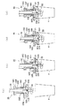
図4(a)から(d)は、蓋部55がカップ4を封止する動作および分離する動作を示し、図4(a)に示す待機状態にあるとき、上蓋55Bはスプリング55Dによって下蓋55A側に押し付けられている。シャフト52は、その先端部に設けられる小径部51に固定ピン51Aを有し、カッター53の固定溝53Aに固定ピン51Aを係止することによってカッター53が回転時に脱落しないように固定している。
【0030】
図4(b)は、蓋部55が下降して上蓋55Bがカップ4の上部に当接した状態を示し、蓋部55が矢印方向に下降すると、まず、下蓋55Aがカップ4内に挿入され、続いて、上蓋55Bがカップ4の上部に当接する。
【0031】
図4(c)は、蓋部55が更に矢印方向に下降して下蓋55Aがカップ4の内壁に当接した状態を示し、下蓋55Aがカップ4の内壁に密接して隙間を封止することにより飲み口側(カップ周縁部)への液漏れを防ぐ。このとき、下蓋55Aはカップ4の中心とカッター53の回転中心が一致するようにカップ4を位置決めする。また、蓋部55の下降によって、スプリング支持部55Eがスプリング55Dを圧縮することにより、上蓋55Bをカップ4の上部に押し付ける。このことによって、カップ4をカップトレイ(図示せず)上に安定的に配置する。
【0032】
図4(d)は、カップ4から蓋部55が分離するときの状態を示し、蓋部55が矢印方向に上昇すると、上蓋55Bはスプリング55Dの弾性力に基づいてカップ4の上部を下方に押し付けていることにより、その反作用によってカップ4に下蓋55Aの分離を促す方向の力を付与する。一方、下蓋55Aは矢印で示す方向に移動することにより、カップ4と下蓋55Aとが分離する。
【0033】
図5は、シャフト取り付け部58を部分的に拡大して示し、駆動モータ(図示せず)の回転軸に取付けられる筒部58Aと、筒部58Aの側面に切欠部58Bを有する。切欠部58Bは、止め金59の幅(紙面における垂直方向の寸法)に応じた開口寸法で形成されている。シャフト52は、切欠部58Bの形状に応じた切欠部52Bと、切欠部52Bの形成部に設けられる段部52Cを有する。段部52Cは、シャフト取り付け部58が空転したとき、シャフト52が自重によってシャフト取り付け部58から脱落するのを防ぐものである。止め金59は、シャフト取り付け部58とシャフト52とを係止する弾性力と強度を有する金属材料によって形成されており、脚部59Aおよび59Bと、脚部59Aおよび59Bとを結合する胴部59Cを有する。シャフト取り付け部58とシャフト52との係止は、まず、シャフト52をa方向より筒部58Aに挿入し、切欠部52Bを切欠部58Bに位置させてb方向より止め金59を挿入することによって行う。同図においては、シャフト取り付け部58がパイプ状で、シャフト52が円柱状であるが、シャフト52がパイプ状でシャフト取り付け部58が円柱状であっても良い。
【0034】
図6(a)は、シャフト取り付け部58とシャフト52との係止状態を示し、(b)および(c)は、(a)に示すX−X部で切断した断面を示す。止め金59による係止によって、シャフト52がシャフト取り付け部58から脱落しないように固定されている。このような係止構造でシャフト取り付け部58を(c)に示すA方向に回転駆動し、シャフト52の回転を妨げる負荷が一定の値を超えると、シャフト取り付け部58がシャフト52との係止に抗して単独で回転する。止め金59の脚部59Aおよび59Bは、シャフト取り付け部58の回転時に弾性変形することによってシャフト取り付け部58を一時的に空転させる。シャフト52は、シャフト取り付け部58が空転しても段部52Cで止め金59を保持しているので長さ方向への移動が規制される。
【0035】
止め金59の形状については、上記する略“コ”の字形に限定されず、過負荷時にシャフト取り付け部58とシャフト52との係合を一時的に解くことができる構造であれば良い。
【0036】
次に、フローズン飲料製造部1の動作を上記した図面および図7(a)から(d)に基づいて説明する。
【0037】
(a)原料供給工程
図7(a)は、フローズン飲料の原料供給工程を示し、操作者が販売要求信号入力部12を操作することにより、制御部13にフローズン飲料の販売要求信号が入力する。制御部13は、製氷部7およびシロップ供給部8にフローズン飲料の販売量に応じた制御信号を出力する。製氷部7は、制御信号の入力に基づいて販売量に基づいて予め設定された量の氷をカップ4に供給する。また、シロップ供給部8は、制御信号の入力に基づいて予め設定された量のシロップをカップ4に供給する。
【0038】
(b)原料粉砕工程
図7(b)は、フローズン飲料の原料粉砕工程を示し、制御部13は、前述の制御信号の出力後、一定時間が経過すると駆動部11に通電開始信号を出力する。駆動部11は、通電開始信号に基づいて駆動モータ26に通電することにより、販売待機位置にある昇降機構部23をカップ4のある位置へ下降させる。また、駆動部11は、昇降機構部23の下降時に駆動モータ50に通電することによってカッター53を回転させる。カッター53の回転は可変させることができ、最初に下降するとき下限位置に達するまでは低速で回転し、その後、高速で回転する。また、この速度可変制御は、製造する飲料等の条件に基づいて変更することができ、例えば、駆動モータ50の駆動開始からある一定時間においては低速で駆動し、一定時間の経過後は高速で駆動するようにしても良い。
【0039】
蓋部支持部材56は、昇降機構部23が下降すると、スプリング57によって下方への弾性力を受ける。このことにより昇降機構部23とともに下降する。蓋部55は、蓋部支持部材56の下降に基づいて最初に上蓋55Bがカップ4の上部に当接し、続いて下蓋55Aがカップ4の内壁に当接し、更に下蓋55Aがカップ4の内壁に密接することによってカップ4が動かないように保持するとともに、カッター53の回転中心とカップの中心軸が一致するようにカップ4の中心位置決めを行う。
【0040】
(c)原料混合工程
図7(c)は、フローズン飲料の原料混合工程を示し、昇降機構部23が下限位置に達すると、垂直位置検出センサ30Bが検出突起23Aによって遮光されてOFFとなり、制御部13は、駆動モータ26の反転信号を駆動部11に出力する。駆動部11は、反転信号に基づいて駆動モータ26を逆回転させることにより、昇降機構部23を上昇させる。制御部13は、昇降機構部23が上昇するときにエンコーダ26Aから入力する出力パルスをカウントする。また、制御部13は、昇降機構部23の上昇時にエンコーダ26Aから入力する出力パルスが記憶部に予め設定されたパルスカウント値となったときに駆動部11に反転信号を出力する。駆動部11は、反転信号に基づいて駆動モータ26を逆回転させることにより、昇降機構部23を支柱24Aおよび24Bに沿って所定の回数で往復移動させる。このようにして垂直位置検出センサ30BのOFF信号とエンコーダ26Aの出力パルスに基づいて昇降機構部23を所定の回数で往復移動させることで、カップ4内では、回転するカッター53によって氷およびシロップの粉砕および混合動作がカップ4の深さ方向に往復して行われる。下蓋55Aは、カッター53の回転に伴って原料がカップ周縁部に漏れ出すことを防止する。
【0041】
(d)待機位置移行工程
図7(d)は、フローズン飲料製造後の待機位置移行工程を示し、制御部13は、プログラムされたフローズン飲料製造工程が終了すると、駆動部11に通電開始信号を出力する。駆動部11は、通電開始信号に基づいて駆動モータ26に通電することにより、昇降機構部23が販売待機位置の方向に移動するようにピニオンギヤ27を回転させる。昇降機構部23が上限位置に達すると、垂直位置検出センサ30Aが検出突起23Aによって遮光されてOFFとなり、制御部13は、駆動モータ26の通電停止信号を駆動部11に出力する。駆動部11は、駆動モータ26への通電を停止し、そのことによって駆動モータ26が停止する。制御部13は、駆動モータ26の回転に伴ってエンコーダ26Aから入力した出力パルスをリセットして販売待機状態となる。このようにして製造されたフローズン飲料を購買者に提供する。
【0042】
図8は、フローズン飲料製造後の洗浄動作を示し、説明を容易にするためにドリップトレイ22Aを切断して示す。以下、ドリップトレイ22Aを洗浄槽として使用する洗浄動作を説明する。ドリップトレイ22A内の廃液を排出口22Bを介して排出した後に排出口22Bを閉じ、カップトレイ3を取り外してドリップトレイ22Aに洗浄水供給部10から配管9を介して洗浄水Wを満たす。この洗浄水Wを満たしたドリップトレイ22Aにカッター53および下蓋55Aを浸漬することによって付着した原料を洗い流す。
【0043】
制御部13は、コントローラから洗浄命令信号を入力すると、駆動部11に通電開始信号を出力する。駆動部11は、通電開始信号に基づいて駆動モータ26に通電することにより、昇降機構部23を洗浄位置まで下降させる。昇降機構部23が洗浄位置に達すると、垂直位置検出センサ30Cが検出突起23Aによって遮光されてOFFとなり、制御部13は、駆動モータ26の通電停止信号を駆動部11に出力する。駆動部11は、駆動モータ26への通電を停止し、そのことによって駆動モータ26が停止する。このとき、カッター53および下蓋55Aはドリップトレイ22Aの内部に配置される。また、上蓋55Bはドリップトレイ22Aの上面を封止する。
【0044】
次に、制御部13は、洗浄水供給部10に洗浄水供給信号を出力する。洗浄水供給部10は、洗浄水供給信号に基づいて配管9に洗浄水Wを送出する。洗浄水Wは、配管9(図示せず)から洗浄水流路55Gを介してドリップトレイ22Aの内部に供給される。制御部13は、一定時間の経過後に洗浄水供給部10に洗浄水停止信号を出力する。洗浄水供給部10は、洗浄水停止信号に洗浄水Wの送出を停止する。続いて、制御部13は、駆動部11に通電開始信号を出力する。駆動部11は、通電開始信号に基づいて駆動モータ50に通電することによりカッター53を低速で回転させる。このことによってドリップトレイ22A内の洗浄水Wが攪拌され、洗浄水に浸漬されているカッター53および下蓋55Aを洗浄する。
【0045】
制御部13は、一定時間の経過後に駆動部11に通電停止信号を出力する。駆動部11は、通電停止信号に基づいて駆動モータ50への通電を停止する。このことにより駆動モータ50が停止する。制御部13は、排出口22Bの電磁弁を開放して洗浄水Wを排出させる。また、駆動部11に通電開始信号を出力して駆動モータ26に電力を供給させる。駆動モータ26は、通電に基づいて昇降機構部23を上昇させる。昇降機構部23が上限位置に達すると、垂直位置検出センサ30Aが検出突起23Aによって遮光されてOFFとなり、制御部13は、駆動モータ26の通電停止信号を駆動部11に出力する。駆動部11は、駆動モータ26への通電を停止し、そのことによって駆動モータ26が停止する。制御部13は、駆動モータ26の回転に伴ってエンコーダ26Aから入力した出力パルスをリセットして販売待機状態となる。
【0046】
上記した洗浄動作においては、操作者が事前にカップトレイ3を取り外す作業が必要となるが、例えば、カップトレイ3を機械的に収納可能なシャッター機構等によって構成し、飲料製造後にカップトレイ3を収容して洗浄工程を行った後に洗浄水Wを排水し、昇降機構部23を販売待機位置に戻し、収容していたカップトレイ3を収容前の状態に復元させるようにしても良い。
【0047】
図9は、カップ4を洗浄槽として用いる他の洗浄動作を示し、説明を容易にするためにカップ4を切断して図示している。カップディスペンサ6からカップトレイ3にカップ4を供給し、昇降機構部23を下降させて蓋部55で開口部を封止した状態で配管9(図示せず)および洗浄水流路55Gを介してカップ4内に洗浄水Wを供給する。次に、駆動モータ50を駆動してカッター53を回転させることにより、洗浄水Wを攪拌してカッター53および下蓋55Aを洗浄するようにしても良い。洗浄工程の終了後は、昇降機構部23を販売待機位置に移動させるとともに洗浄水Wの満たされたカップ4をカップトレイ3から取り除く。
【0048】
上記した第1の実施の形態の飲料製造装置によると、氷とシロップをカップ4に供給し、カップ4を下蓋55Aおよび上蓋55Bで封止した状態でカッター53を回転させることによって氷を粉砕するとともにシロップと混合するフローズン飲料製造部1を有するようにしたので、カップ4の外に原料が漏れることなく、かつ、カップ4を安定した状態でフローズン飲料を速やかに製造することができる。
【0049】
また、カップ4を封止した状態で氷とシロップの攪拌をカップの深さ方向に往復させるので、カップ4内の上部側と底部側とで混合むらのない、均一な口当たりの良いフローズン飲料を製造することができる。
【0050】
また、下蓋55Aおよび上蓋55Bを有してカッティング部5とともに昇降可能な蓋部55をシャフト52に同軸的に設けたことによって、カップ4を二重に封止でき、カップ4の外への原料の漏れを確実に防げる。また、下蓋55Aがカップ4に内接する形状を有することによって、飲み口付近に原料が付着して見た目を損ねることを防ぐことができる。また、カップ4に下蓋55Aが内接する際に下蓋55Aと同軸的に設けられる上蓋55Bがスプリング55Dによってカップ4の上部に押し付けられることにより、カップトレイ3にカップ4が安定して配置される。また、上蓋55Bは、下蓋55Aの分離動作に際して下蓋55Aの分離方向と相反する方向にカップ4を押すことから、下蓋55Aとカップ4の分離が確実に行える。
【0051】
また、下蓋55Aをカップ4の内壁に密接させることによって、カップ4の保持が確実に行われるとともにカッター53の回転中心とカップの中心軸とを一致させることができ、そのことによってカッター53の回転に基づく均一な攪拌効果が得られる。また、カッター53の回転中心とカップの中心軸とをずらして配置するようにしても良く、カッター53の回転に基づいてカップ4の内部に発生する渦の形成状態を変化させて異なった攪拌性を付与できる。
【0052】
また、カッティング部5に設けられるシャフト取り付け部58とシャフト52とを止め金59によって弾性的に固定したことによって、粘性の大なる原料の混合や固い氷の粉砕に際してシャフト52に一定値以上の負荷が加わったときに簡素なクラッチ構造に基づいてシャフト取り付け部58を一時的に空転させることができ、駆動モータ50を高速で回転駆動しても焼損やカッター53の破損を防いで原料の粉砕動作および混合動作を速やかに、確実に行うことができる。本実施の形態では、カッターの駆動を制限する駆動制限部として止め金による回転トルク制限部を説明したが、例えば、磁石を用いた磁力結合によるクラッチ構造によってカッター53の駆動を制限するようにしても良い。
【0053】
蓋部55を構成する下蓋55Aおよび上蓋55Bの表面にフッ素コーティングを施しているので、飲料製造後の洗浄時に下蓋55Aの洗浄性を向上させることができる。
【0054】
上蓋55Bの形状は、図示した円板状に限定されず、例えば、十字形の蓋、複数の棒状物体を放射状に配設した扇風機のカバーの様な構成の蓋であってもよい。
【0055】
また、上記した飲料製造工程では、昇降機構部23の下限位置を基準位置として上昇量をエンコーダ26Aの出力パルスに基づいて制御しているが、昇降機構部23の上限位置を基準位置として下降量をエンコーダ26Aの出力パルスに基づいて制御することによりカップの深さ方向に攪拌を行わせることも可能である。以下、その動作について説明する。
【0056】
制御部13は、昇降機構部23が上限位置以外の場所にあるとき、駆動部11に通電信号を出力して昇降機構部23を上限位置に移動させる。昇降機構部23が上限位置に達すると、垂直位置検出センサ30Aが検出突起23Aによって遮光されてOFFとなり、制御部13は、駆動モータ26の通電停止信号を駆動部11に出力する。駆動部11は、駆動モータ26への通電を停止し、そのことによって駆動モータ26が停止する。制御部13は、駆動モータ26の回転に伴ってエンコーダ26Aから入力した出力パルスをリセットする。
【0057】
次に、制御部13は、一定時間が経過すると駆動部11に通電開始信号を出力する。駆動部11は、通電開始信号に基づいて駆動モータ26に通電することにより、販売待機位置にある昇降機構部23をカップ4のある位置へ下降させる。制御部13は、昇降機構部23の下降時にエンコーダ26Aの出力パルスをカウントし、所定のパルスカウント値となったときに駆動モータ26の通電停止信号を駆動部11に出力する。また、駆動部11は、昇降機構部23の下降時に駆動モータ50に通電することによってカッター53を回転させる。
【0058】
蓋部支持部材56は、昇降機構部23が下降すると、スプリング57によって下方への弾性力を受ける。このことにより昇降機構部23とともに下降する。蓋部55は、蓋部支持部材56の下降に基づいて最初に上蓋55Bがカップ4の上部に当接し、続いて下蓋55Aがカップ4の内壁に当接し、更に下蓋55Aがカップ4の内壁に密接することによってカップ4が動かないように保持するとともに、カッター53の回転中心とカップの中心軸が一致するようにカップ4の中心位置決めを行う。
【0059】
制御部13は、エンコーダ26Aから入力する出力パルスをカウントして、カップ4のサイズに応じて記憶部に予め設定されたパルスカウント値となったときに駆動モータ26を逆回転させる。昇降機構部23は、駆動モータ26の逆回転に基づいて上昇する。また、制御部13は、逆回転時にエンコーダ26Aから入力する出力パルスが記憶部に予め設定されたパルスカウント値となったときに駆動モータ26を逆回転させることにより、昇降機構部23を支柱24Aおよび24Bに沿って所定の回数で往復移動させる。このようにして昇降機構部23を所定の回数で往復移動させることも可能である。
【0060】
また、上記した昇降機構部23を往復移動させるとき、カップサイズや飲料のタイプ等に応じて定まる好ましい深さ方向の範囲を設定し、エンコーダ26Aから入力する出力パルスに基づいて設定された範囲でカッター53による攪拌動作が往復するように昇降機構部23の往復移動を制御するようにしても良い。また、垂直位置検出センサ30A、30B、および30Cによって昇降機構部23の位置検出を行うとともにエンコーダ26Aから入力する出力パルスに基づいて昇降機構部23を位置制御するようにしても良い。このような構成とすることで、センサ位置を基準とするパルスカウント値に基づいて昇降機構部23を希望する位置に配置することが可能になる。
【0061】
上記した実施の形態では、フローズン飲料を製造する飲料製造装置を説明したが、カップに供給する原料として氷とシロップ等の液体を供給する以外に、例えば、氷だけを供給するようにしても良い。このような場合に、固形分として供給される氷は水を凍らせたものに限定されず、シロップ等の原料を氷結させたもの、あるいは、シャーベット状に凍らせたものを用いても良い。また、氷中に果肉等の固形分を含むものであっても良い。また、お茶、コーヒー、又は紅茶等の飲料の抽出部を有する飲料製造装置では、抽出された飲料をシロップの代わりにフローズン飲料の原料としてカップに供給するようにしても良く、そのことによってフローズン飲料の種類を増やすことができる。
【0062】
また、製造される飲料についてもフローズン飲料に限定されず、豆等の固形分をカッター53で粉砕して混合されたスープ等の飲料製造用に適用することもできる。
【0063】
図10は、第2の実施の形態として、上記したフローズン飲料製造部1で説明したカップ内での原料混合機構を適用したカップ式飲料の自動販売機を示し、調理部60は、水平方向に延びる搬送機構61と、カップCを供給するカップ供給装置62と、クリーム、コーヒー、および砂糖等の粉末原料をカップCに供給する原料貯蔵部63A、63B,および63Cを備えたキャニスタ63と、カップCにレモンシロップ、生クリーム等のシロップをシロップポンプ64Aの送出動作に基づいて送出管64Bから送出するシロップ供給装置64と、カップCに湯を供給する湯タンク65と、粉末原料と湯との攪拌(調理)、氷等の固形分の粉砕を行う回転可能なカッター部66Aを有する攪拌機構66と、アイス飲料の調理に使用する氷を製氷し、貯水する製氷機67を有する。
【0064】
搬送機構61は、左右方向(図10に対し)水平に直線的に延びる支持フレーム68、支持フレーム68の両端部にそれぞれ回転自在に軸支された駆動プーリ69Aおよび従動プーリ69B、駆動プーリ69Aおよび従動プーリ69Bの間に掛け渡した無端の搬送ベルト70、駆動プーリ69Aを作動させる搬送モータ71、および、支持フレーム68と平行して設けたサブフレーム72によって構成された主搬送部73と、一端を搬送ベルト70に固定し、他端をサブフレーム72上に載置して設けられ、両端部にそれぞれ回転自在に軸支された駆動プーリ74Aおよび従動プーリ74Bを有する支持フレーム75、駆動プーリ74Aおよび従動プーリ74Bの間に掛け渡した無端の搬送ベルト76、駆動プーリ74Aを作動させる搬送モータ77、搬送ベルト70の作動に伴って支持フレーム75が支持フレーム68面上を転勤するように設けたローラ78、および、サブフレーム72面上を転勤するように設けたローラ79によって構成されたカップ保持機構搬送部80を有し、カップ保持機構搬送部80は、搬送ベルト76に固定されたカップ保持機構81を有している。
【0065】
カップ保持機構搬送部80は、搬送モータ71を回転させて搬送ベルト70を駆動すると、ローラ78が支持フレーム68、ローラ79がサブフレーム72のそれぞれの面上を転動することにより、図示する左右方向に円滑に移動する。
【0066】
カップ保持機構81は、搬送ベルト76の搬送動作に応じて支持フレーム75上を転動できるようにローラ82を有する。搬送モータ77を回転させて搬送ベルト76を駆動すると、ローラ82が支持フレーム75の面上を転動することにより、図示する前後方向に円滑に移動する。
【0067】
搬送モータ71および搬送モータ77は、図示しない制御部から出力される駆動信号に基づいて正転方向又は逆転方向に回転し、そのことによってカップ保持機構81を、同図における前後左右方向へ自在に移動させる。
【0068】
また、カップ保持機構81は、カップ供給装置62から供給されるカップCを受けるカップ受台83と、カップCの胴部を把持するカップ把持アーム84とを有し、カップ受台83は、図示しないカップ受台移動機構により、カップCのサイズ(大、中、小)に応じたカップ高さ(上下)方向に移動する。また、カップ把持アーム84は、図示しないアーム開閉機構によってカップCのサイズに応じたアーム間隔に一対のアームを開閉することによりカップ受台83で受けたカップCを把持する。
【0069】
図11(a)は、攪拌機構66のカッター部66Aを部分的に示し、カッター部66Aは、カップ4内の原料を粉砕、混合、および攪拌するカッター660と、攪拌機構66に収容された駆動モータ50の回転に基づいてカッター660を回転駆動する駆動軸661と、駆動軸661と同軸的に設けられてカップCに内接する形状を有する下蓋662と、下蓋662と一体的に設けられる筒状部662Aと、筒状部662Aに形成されるスプリング支持部662Bと、筒状部662Aの外周に沿って摺動自在に設けられる上蓋663と、スプリング支持部662Bと上蓋663との間に設けられて上蓋663を下蓋662の方向に押し付けるスプリング664と、下蓋662および上蓋663を下方に押し付けるスプリング665を有する。
【0070】
また、第2の実施の形態においても、第1の実施の形態で説明したシャフト取り付け部58と止め金59からなる回転トルク制限部を介して駆動モータ50から駆動軸661に回転トルクを伝達する構成を有する。
【0071】
下蓋662は、駆動軸661に同軸的に設けられるスプリング665によって、上記したカップ保持機構81に保持されて搬送されたカップCの内壁面に内接するように形成されている。カップ保持機構81は、カップCの搬送時にカッター部66AとカップCとが接触しない高さ位置にカップCを配置する。カップCに受容されて搬送された原料は、カッター660の回転に基づいて粉砕、混合される。
【0072】
図11(b)は、カップ保持機構81がカップCを上昇させた状態を示し、カップ保持機構81は、カップCの中心がカッター660の回転中心に一致する位置にカップCを配置し、図示するようにカップ受台83を図示しない昇降装置によって上昇させる。カップCが上昇すると、まず、下蓋662がカップC内に挿入され、続いて、上蓋663がカップCの上部に当接する。次に、下蓋662がカップCの内壁に密接する。次に、上蓋663がスプリング664の弾性力に基づいてカップCの上部に密接する。カップ保持機構81は、図示するようにカップCの内部に原料を収容した状態で昇降動作を行うことにより、カップCの内部を深さ方向に攪拌する。カップCが上昇するときは、スプリング664が弾性変形することによって、下蓋662および上蓋663をそれぞれカップCに密接させたままカッター660をカップCの下方向に相対的に移動させる。カップCが下降するときは、圧縮されたスプリング664が伸びることによって、下蓋662および上蓋663をそれぞれカップCに密接させたままカッター660をカップCの上方向に相対的に移動させる。
【0073】
以下に、上記したカップ式飲料の自動販売機で、フローズン飲料を製造する動作を説明する。
【0074】
購買者によって図示しない飲料選択ボタンが押されると、制御部は、カップ供給装置62にカップ供給動作を実行させる。カップ供給装置62はカップ保持機構81にカップCを供給する。カップ保持機構81は、カップ受台83でカップCを受けるとともにカップ把持アーム84でカップCを保持固定する。次に、制御部は、搬送モータ71と搬送モータ77を駆動してカップ保持機構81を原料の供給位置に移動させる。この移動によって、カップCにはシロップと氷が供給される。
【0075】
次に、制御部は、カップ保持機構81を攪拌機構66のある位置に移動させる。制御部は、カップ把持アーム84で把持しているカップCを図示しない昇降装置によってカップ受台83とともにカッター660の方向に上昇させる。まず、下蓋662がカップC内に挿入され、続いて、上蓋663がカップCの上部に当接する。次に、下蓋662がカップCの内壁に密接する。次に、上蓋663がスプリング664の弾性力に基づいてカップCの上部に密接することによりカップCを封止する。制御部は、上蓋663がカップCの上部に当接した後にカッター660を回転駆動する図示しないモータに通電してカッター660を回転駆動する。カッター660は、封止されたカップ内の氷およびシロップを粉砕、混合する。このカップ受台83は、カッター部66Aで原料の粉砕、混合を行っている間に上下に移動する。このことにより、カップC内のフローズン飲料を深さ方向に攪拌する。
【0076】
制御部は、上記した深さ方向の攪拌が規定の回数となったとき、カップ受台83を図11(a)に示す高さ位置に配置させる。次に、カップ保持機構搬送部80を駆動してカップ保持機構81を図示しない販売口に移動させる。カップ把持アーム84は、把持しているカップCを販売口で分離する。制御部は、カップ保持機構81を待機位置に移動させる。このようにしてフローズン飲料を購入客に販売する。
【0077】
第2の実施の形態によると、カッター660に対してカップ保持機構81で保持しているカップCを昇降させることによって、固形分を含む原料の粉砕、混合を効率良く行えるので、フローズン飲料を容易に製造することができ、大掛かりな機器改装や、設備の追加を行うことなくカップ式飲料の自動販売機において、販売飲料のバリエーションを増やすことができる。
【0078】
なお、図11に示す構成では、カッター部66Aを固定系に設けたものとして説明したが、第1の実施の形態で説明した昇降機構部によって昇降可能な構成としても良く、カップ受台83に載置されたカップCの昇降動作に応じてカッター部66Aを昇降させるようにしても良い。このような構成によると、カップ受台83のみを移動させる構成と比べてカップCの深さ方向への攪拌性を損なうことなくカップ受台83の垂直移動量を半減させることができる。
【0079】
上記した第1および第2の実施の形態では、カップを封止する蓋部については、カップ内壁との接触性を高めるためにカップ接触部分をテーパー状に形成しているが、例えば、フッ素ゴム等の弾性材料で形成された環状のシールリングをカップ接触部分に設けるようにしても良い。また、蓋部の底部(カップ側)を肉抜きしてカッターを断面内に収容可能な形状とすることで、カッターの露出を防ぐことができ、カッターに不用意に接触することによる事故の発生を防ぐことができる。
【0080】
また、第1および第2の実施の形態の飲料製造装置では、液体原料としてのシロップと氷を用いたフローズン飲料の他に、インスタントコーヒーやインスタントココア等の粉末原料と氷とでフローズン飲料を調理することも可能である。粉末原料を用いる場合は、溶け残りを防ぐために粉末原料を予め少量の水又は湯で溶解して用いることが好ましい。
【0081】
【発明の効果】
以上説明した通り、本発明の飲料製造装置によると、容器の内壁に内接する蓋と容器に外接する蓋によって容器を覆った状態で容器内の原料を粉砕し、粉砕時の負荷に応じてカッターの駆動を制限するようにしたので、カップの安定性を損なうことなく、固形分を含む原料の粉砕および混合を速やかに、確実に行うことができる。
【図面の簡単な説明】
【図1】本発明の第1の実施の形態に係る飲料製造装置の概略構成図
【図2】フローズン飲料製造部の一方を開放した側面図
【図3】フローズン飲料製造部の一方を開放した背面図
【図4】(a)から(d)は、蓋部がカップを封止する動作および分離する動作を示す動作図
【図5】シャフト取り付け部を部分的に拡大した分解図
【図6】(a)は、シャフト取り付け部の部分拡大図、(b)は、(a)に示すX−X部で切断したシャフト取り付け部の断面図、(c)は、シャフト取り付け部が回転した状態を示す断面図
【図7】(a)から(d)は、フローズン飲料製造部によってフローズン飲料を製造するときの動作図
【図8】フローズン飲料製造部の洗浄工程を示す部分断面図
【図9】フローズン飲料製造部の他の洗浄工程を示す部分断面図
【図10】本発明の第2の実施の形態に係るカップ式飲料の自動販売機の概略構成図
【図11】カップ式飲料の自動販売機の攪拌機構の概略構成図
【符号の説明】
1,フローズン飲料製造部 2,本体 3,カップトレイ 4,カップ
5,カッティング部 6,カップディスペンサ 7,製氷部
8,シロップ供給部 9,配管 10,洗浄水供給部 11,駆動部
12,販売要求信号入力部 13,制御部 20,上部21A,前面部
21B,側面部 21C,背面部 21D,開口部 22,基部
22A,ドリップトレイ 22B,排出口 23,昇降機構部
23A,検出突起 24A,支柱 25,ラック部26,駆動モータ
26A,エンコーダ 27,ピニオンギヤ 28,減速機
29,支持部 30A,垂直位置検出センサ 30B,垂直位置検出センサ
30C,垂直位置検出センサ 50,駆動モータ 51,小径部
51A,固定ピン 52,シャフト 52B,切欠部 52C,段部
53,カッター 53A,固定溝 54,駆動モータ支持部
55,蓋部 55A,下蓋 55B,上蓋 55C,筒状部
55D,スプリング 55E,スプリング支持部 55F,配管接続部
55G,洗浄水流路 56,蓋部支持部材 57,スプリング
58,シャフト取り付け部 58A,筒部 58B,切欠部
59,止め金 59A,脚部 59B,脚部 59C,胴部
60,調理部 61,搬送機構 62,カップ供給装置
63,キャニスタ 63A,原料貯蔵部 64,シロップ供給装置
64A,シロップポンプ 64B,送出管 65,湯タンク
66,攪拌機構 66A,カッター部 67,製氷機
68,支持フレーム 69A,駆動プーリ 69B,従動プーリ
70,搬送ベルト 71,搬送モータ 72,サブフレーム
73,主搬送部 74A,駆動プーリ 74B,従動プーリ
75,支持フレーム 76,搬送ベルト 77,搬送モータ
78,ローラ 79,ローラ 80,カップ保持機構搬送部
81,カップ保持機構 82,ローラ 83,カップ受台
84,カップ把持アーム 660,カッター 661,駆動軸
662,下蓋 662A,筒状部 662B,スプリング支持部
663,上蓋 664,スプリング 665,スプリング[0001]
BACKGROUND OF THE INVENTION
The present invention relates to a beverage production apparatus, and more particularly to a beverage production apparatus for producing a sherbet-like beverage (frozen beverage) by mixing syrup and ice supplied to a cup in the cup.
[0002]
[Prior art]
2. Description of the Related Art Conventionally, there is known a beverage manufacturing apparatus that manufactures a sherbet-like beverage (hereinafter referred to as a frozen beverage) by mixing (or stirring) syrup and ice in a tank. In this beverage production device, there is a non-carbonated type that stirs while cooling dilution water and syrup inside an open-air tank, and agitation while cooling dilution water and syrup inside a pressure tank pressurized with carbon dioxide gas. There is a carbonic acid type.
[0003]
An example of such a beverage production apparatus is disclosed in Japanese Patent Application Laid-Open No. 2000-163651. According to this beverage manufacturing apparatus, a cooling cylinder with an agitating blade that also serves as an auger type ice maker is provided in an open air tank, and ice is made by an ice maker while mixing diluted water and syrup. While cooling the mixture of ice and syrup sent out from the ice making machine with a stirring blade, it is possible to form a sherbet-like frozen beverage with a good mouthfeel and a refreshing feeling, while mixing and cooling the syrup and dilution water Since the apparatus for frozen drinks, such as a tank and ice making machine to perform, is needed, there exists a problem that application to the vending machine etc. with restrictions on apparatus size is difficult.
[0004]
An example of a beverage production apparatus that performs mixing of ingredients and the like in a cup is disclosed in, for example, Japanese Utility Model Publication No. 4-54546. In this beverage production apparatus, ingredients and dilution water are contained in a cup, and the beverage is prepared by stirring and mixing the ingredients and dilution water in the cup based on the rotational drive of the stirring blade with the cup upper surface covered with a cup cover. ing.
[0005]
[Problems to be solved by the invention]
However, according to the conventional beverage production apparatus, the mixing of liquids and powders is promoted by stirring. Therefore, the rotational force and grinding force of the stirring blades are used to pulverize raw materials containing hard solids such as ice in the cup. On the other hand, if the rotational speed of the stirring blade is increased, the raw material scatters from the cup and contaminates the surroundings, and the stirring may cause the cup to become unstable. If the upper surface of the cup is covered to prevent this, scattering of the raw material can be prevented, but there is a problem that the raw material adheres to the drinking portion of the inner wall of the cup and the appearance is impaired.
[0006]
Accordingly, an object of the present invention is to provide a beverage production apparatus capable of quickly and reliably performing crushing and mixing of raw materials containing solids without impairing the stability of the cup.
[0007]
[Means for Solving the Problems]
In order to achieve the above-described object, the present invention provides a container containing a raw material containing a solid content, a cutting unit having a cutter inserted into the container and pulverizing the solid content based on a rotation operation,
A first lid that is inscribed in the container when the cutter is inserted and a second lid that is in contact with the container;
Provided is a beverage production apparatus having a control means for stirring the ingredients based on rotation of the cutter in the depth direction of the container by relatively moving the container sealed with the lid and the cutting part.
[0008]
In addition, in order to achieve the above-described object, the present invention includes a container for containing a raw material containing a solid content,
A cutter that is inserted into the container and crushes the solid content based on a rotation operation, and a cutting unit that has a drive limiting unit that restricts driving of the cutter according to a load during crushing of the raw material,
A first lid that is inscribed in the container when the cutter is inserted and a second lid that is in contact with the container;
Provided is a beverage production apparatus having a control means for stirring the ingredients based on rotation of the cutter in the depth direction of the container by relatively moving the container sealed with the lid and the cutting part.
[0009]
In addition, in order to achieve the above-described object, the present invention includes a container for containing a raw material containing a solid content,
A cutter that is inserted into the container and crushes the solid content based on a rotation operation, a drive motor that generates a drive torque that rotationally drives the cutter, a rotary shaft that transmits the drive torque to the cutter, and the rotation A cutting unit provided on a shaft and having a rotational torque limiting unit that limits transmission of the rotational torque in accordance with a load during pulverization of the raw material;
A first lid that is inscribed in the container when the cutter is inserted and a second lid that is in contact with the container and arranged in series coaxially with the rotating shaft;
Provided is a beverage production apparatus having a control means for stirring the ingredients based on rotation of the cutter in the depth direction of the container by relatively moving the container sealed with the lid and the cutting part.
[0010]
According to the beverage manufacturing apparatus described above, by crushing the raw material containing the solid content inside the container double-sealed by the first lid and the second lid, Leakage is prevented by the first lid inscribed in the container. Further, the second lid that circumscribes the container prevents the container from becoming unstable when the cutter rotates. Moreover, when the load fluctuation at the time of raw material crushing becomes large, the drive of a cutter is restrict | limited and a cutting part is protected.
[0011]
DETAILED DESCRIPTION OF THE INVENTION
Hereinafter, embodiments of the present invention will be described in detail with reference to the drawings.
[0012]
FIG. 1 shows a schematic configuration of a beverage production apparatus according to a first embodiment of the present invention. A
[0013]
The
[0014]
The
[0015]
The
[0016]
The
[0017]
The
[0018]
The ice making unit 7 supplies ice formed by freezing drinking water for iced drinks based on an ice making type such as a rod type or an auger type.
[0019]
The
[0020]
The
[0021]
FIG. 2 shows an open side surface of the frozen
[0022]
The elevating
[0023]
The
[0024]
The
[0025]
The
[0026]
Further, the
[0027]
FIG. 3 shows the frozen
[0028]
The
[0029]
4 (a) to 4 (d) show the operation of the
[0030]
FIG. 4B shows a state in which the
[0031]
FIG. 4C shows a state in which the
[0032]
FIG. 4D shows a state in which the
[0033]
FIG. 5 is a partially enlarged view of the
[0034]
FIG. 6A shows a locked state of the
[0035]
The shape of the
[0036]
Next, operation | movement of the frozen
[0037]
(A) Raw material supply process
FIG. 7A shows a frozen beverage raw material supply process. When the operator operates the sales request
[0038]
(B) Raw material grinding step
FIG. 7B shows a raw material crushing step for frozen beverage, and the
[0039]
The
[0040]
(C) Raw material mixing step
FIG. 7 (c) shows a raw material mixing process for frozen beverage. When the elevating
[0041]
(D) Standby position transition process
FIG.7 (d) shows the standby position transfer process after frozen beverage manufacture, and the
[0042]
FIG. 8 shows a cleaning operation after manufacturing the frozen beverage, and shows the
[0043]
When the
[0044]
Next, the
[0045]
The
[0046]
In the above-described cleaning operation, the operator needs to remove the
[0047]
FIG. 9 shows another cleaning operation using the
[0048]
According to the beverage manufacturing apparatus of the first embodiment described above, ice and syrup are supplied to the
[0049]
In addition, since ice and syrup are reciprocated in the depth direction of the cup with the
[0050]
In addition, by providing the
[0051]
Further, by bringing the
[0052]
Further, since the
[0053]
Since the surfaces of the
[0054]
The shape of the
[0055]
Further, in the beverage manufacturing process described above, the rising amount is controlled based on the output pulse of the
[0056]
When the
[0057]
Next, the
[0058]
The
[0059]
The
[0060]
Moreover, when reciprocating the above-mentioned raising /
[0061]
In the above-described embodiment, the beverage manufacturing apparatus that manufactures frozen beverages has been described. However, in addition to supplying liquid such as ice and syrup as raw materials to be supplied to the cup, for example, only ice may be supplied. . In such a case, the ice supplied as the solid content is not limited to the one frozen in water, and one obtained by freezing raw materials such as syrup or the one frozen in a sherbet shape may be used. Moreover, solid content, such as pulp, may be contained in ice. In addition, in a beverage production apparatus having a beverage extraction unit such as tea, coffee, or tea, the extracted beverage may be supplied to the cup as a raw material for frozen beverage instead of syrup. The number of types can be increased.
[0062]
Also, the beverage to be produced is not limited to frozen beverages, and can also be applied for producing beverages such as soups in which solids such as beans are crushed with a
[0063]
FIG. 10 shows a cup-type beverage vending machine to which the raw material mixing mechanism in the cup described in the above-described frozen
[0064]
The
[0065]
When the
[0066]
The
[0067]
The
[0068]
The
[0069]
FIG. 11A partially shows a
[0070]
Also in the second embodiment, the rotational torque is transmitted from the
[0071]
The
[0072]
FIG. 11B shows a state in which the
[0073]
Below, the operation | movement which manufactures a frozen drink with the above-mentioned cup-type drink vending machine is demonstrated.
[0074]
When a beverage selection button (not shown) is pressed by the purchaser, the control unit causes the
[0075]
Next, the control unit moves the
[0076]
When the above-described stirring in the depth direction reaches the specified number of times, the control unit places the
[0077]
According to the second embodiment, by raising and lowering the cup C held by the
[0078]
In the configuration shown in FIG. 11, the
[0079]
In the first and second embodiments described above, the lid that seals the cup has a cup contact portion formed in a tapered shape in order to improve the contact with the inner wall of the cup. An annular seal ring formed of an elastic material such as the above may be provided at the cup contact portion. In addition, the bottom of the lid (the cup side) is thinned out so that the cutter can be accommodated in the cross section, so that the exposure of the cutter can be prevented and accidents caused by inadvertent contact with the cutter. Can be prevented.
[0080]
In addition, in the beverage manufacturing apparatus according to the first and second embodiments, in addition to frozen beverages using syrup and ice as liquid ingredients, frozen beverages are cooked with powdered ingredients such as instant coffee and instant cocoa and ice. It is also possible to do. When using a powder raw material, it is preferable to dissolve the powder raw material in advance with a small amount of water or hot water in order to prevent undissolved residue.
[0081]
【The invention's effect】
As described above, according to the beverage production apparatus of the present invention, the raw material in the container is crushed in a state where the container is covered with the lid inscribed on the inner wall of the container and the lid circumscribed on the container, and the cutter is cut according to the load at the time of pulverization. Therefore, the raw material containing solids can be pulverized and mixed quickly and reliably without impairing the stability of the cup.
[Brief description of the drawings]
FIG. 1 is a schematic configuration diagram of a beverage production apparatus according to a first embodiment of the present invention.
FIG. 2 is a side view of one of the frozen beverage production departments opened.
FIG. 3 is a rear view with one side of the frozen beverage production department opened.
FIGS. 4A to 4D are operation diagrams illustrating an operation in which a lid portion seals and separates a cup.
FIG. 5 is an exploded view in which the shaft mounting part is partially enlarged.
6A is a partially enlarged view of the shaft attachment portion, FIG. 6B is a cross-sectional view of the shaft attachment portion cut at XX shown in FIG. 6A, and FIG. Sectional view showing the rotated state
FIGS. 7A to 7D are operation diagrams when a frozen beverage is manufactured by the frozen beverage manufacturing unit;
FIG. 8 is a partial cross-sectional view showing the cleaning process of the frozen beverage production department
FIG. 9 is a partial cross-sectional view showing another cleaning process of the frozen beverage manufacturing unit.
FIG. 10 is a schematic configuration diagram of a cup-type beverage vending machine according to a second embodiment of the present invention.
FIG. 11 is a schematic configuration diagram of a stirring mechanism of a cup-type beverage vending machine.
[Explanation of symbols]
1, Frozen
5, cutting
8,
12. Sales request
21B,
22A, drip tray 22B,
23A,
26A,
29,
30C, vertical
51A, fixing
53,
55, cover
55D,
55G, cleaning
58,
59,
60,
63,
64A,
66, stirring
68,
70,
73,
75,
78,
81,
84,
662,
663,
Claims (8)
前記容器に挿入されて前記固形分を回転動作に基づいて粉砕するカッターを有するカッティング部と、
前記カッターの挿入時に前記容器に内接する第1の蓋および前記容器に外接する第2の蓋からなる蓋部と、
前記蓋部で封じた前記容器と前記カッティング部とを相対移動させることによって前記容器の深さ方向に前記カッターの回転に基づく前記原料の攪拌を行わせる制御手段を有することを特徴とする飲料製造装置。A container for storing a raw material containing solids;
A cutting unit having a cutter inserted into the container and pulverizing the solid content based on a rotation operation;
A first lid that is inscribed in the container when the cutter is inserted and a second lid that is in contact with the container;
Beverage production comprising control means for stirring the ingredients based on rotation of the cutter in the depth direction of the container by relatively moving the container sealed by the lid and the cutting part apparatus.
前記容器に挿入されて前記固形分を回転動作に基づいて粉砕するカッターと、前記原料の粉砕時の負荷に応じて前記カッターの駆動を制限する駆動制限部を有するカッティング部と、
前記カッターの挿入時に前記容器に内接する第1の蓋および前記容器に外接する第2の蓋からなる蓋部と、
前記蓋部で封じた前記容器と前記カッティング部とを相対移動させることによって前記容器の深さ方向に前記カッターの回転に基づく前記原料の攪拌を行わせる制御手段を有することを特徴とする飲料製造装置。A container for storing a raw material containing solids;
A cutter that is inserted into the container and crushes the solid content based on a rotation operation, and a cutting unit that has a drive limiting unit that restricts driving of the cutter according to a load during crushing of the raw material,
A first lid that is inscribed in the container when the cutter is inserted and a second lid that is in contact with the container;
Beverage production comprising control means for stirring the ingredients based on rotation of the cutter in the depth direction of the container by relatively moving the container sealed by the lid and the cutting part apparatus.
前記容器に挿入されて前記固形分を回転動作に基づいて粉砕するカッターと、前記カッターを回転駆動する駆動トルクを発生する駆動モータと、前記駆動トルクを前記カッターに伝達する回転軸と、前記回転軸に設けられて前記原料の粉砕時の負荷に応じて前記回転トルクの伝達を制限する回転トルク制限部を有するカッティング部と、
前記カッターの挿入時に前記容器に内接する第1の蓋および前記容器に外接する第2の蓋を前記回転軸と同軸的に直列に配置した蓋部と、
前記蓋部で封じた前記容器と前記カッティング部とを相対移動させることによって前記容器の深さ方向に前記カッターの回転に基づく前記原料の攪拌を行わせる制御手段を有することを特徴とする飲料製造装置。A container for storing a raw material containing solids;
A cutter that is inserted into the container and crushes the solid content based on a rotation operation, a drive motor that generates a drive torque that rotationally drives the cutter, a rotary shaft that transmits the drive torque to the cutter, and the rotation A cutting unit provided on a shaft and having a rotational torque limiting unit that limits transmission of the rotational torque in accordance with a load during pulverization of the raw material;
A first lid that is inscribed in the container when the cutter is inserted and a second lid that is in contact with the container and arranged in series coaxially with the rotating shaft;
Beverage production comprising control means for stirring the ingredients based on rotation of the cutter in the depth direction of the container by relatively moving the container sealed by the lid and the cutting part apparatus.
前記回転軸に形成された第2の切欠部と、
前記筒状部に前記回転軸を挿入して前記第1および第2の切欠部が一致する位置を弾性的に係止する止め金を有することを特徴とする請求項第4項記載の飲料製造装置。The rotational torque limiting portion includes a first notch portion formed in a cylindrical portion attached to a drive shaft of the drive motor,
A second notch formed in the rotating shaft;
5. The beverage production according to claim 4, further comprising a stopper that elastically locks the position where the first and second cutouts coincide with each other by inserting the rotating shaft into the cylindrical part. apparatus.
Priority Applications (1)
| Application Number | Priority Date | Filing Date | Title |
|---|---|---|---|
| JP2001359725A JP3920632B2 (en) | 2001-11-26 | 2001-11-26 | Beverage production equipment |
Applications Claiming Priority (1)
| Application Number | Priority Date | Filing Date | Title |
|---|---|---|---|
| JP2001359725A JP3920632B2 (en) | 2001-11-26 | 2001-11-26 | Beverage production equipment |
Publications (2)
| Publication Number | Publication Date |
|---|---|
| JP2003160197A JP2003160197A (en) | 2003-06-03 |
| JP3920632B2 true JP3920632B2 (en) | 2007-05-30 |
Family
ID=19170679
Family Applications (1)
| Application Number | Title | Priority Date | Filing Date |
|---|---|---|---|
| JP2001359725A Expired - Fee Related JP3920632B2 (en) | 2001-11-26 | 2001-11-26 | Beverage production equipment |
Country Status (1)
| Country | Link |
|---|---|
| JP (1) | JP3920632B2 (en) |
Families Citing this family (10)
| Publication number | Priority date | Publication date | Assignee | Title |
|---|---|---|---|---|
| JP4616618B2 (en) * | 2004-10-27 | 2011-01-19 | 株式会社大川原製作所 | Cleaning method for conical stirring device |
| DE102009044077A1 (en) * | 2009-09-23 | 2011-04-07 | Gako Konietzko Gmbh | Program controlled mixer and method for its control |
| JP5932629B2 (en) * | 2012-12-25 | 2016-06-08 | 株式会社カジワラ | Stirrer |
| JP6358986B2 (en) * | 2015-06-09 | 2018-07-18 | 株式会社ニフコ | Mixing equipment |
| JP6469917B2 (en) * | 2018-04-09 | 2019-02-13 | 株式会社ニフコ | Mixing equipment |
| CN109872459B (en) * | 2019-04-16 | 2024-06-28 | 上海氦豚机器人科技有限公司 | Cup capping machine and capping mechanism |
| CN110693293A (en) * | 2019-10-31 | 2020-01-17 | 小熊电器股份有限公司 | Multifunctional food processor |
| CN110898970A (en) * | 2019-12-13 | 2020-03-24 | 武汉工程大学 | Agitating unit is smashed to cosmetics |
| JP7303573B2 (en) * | 2020-07-21 | 2023-07-05 | TechMagic株式会社 | Beverage automatic serving system |
| CN116921031B (en) * | 2023-08-10 | 2024-01-30 | 河北汇源食品饮料有限公司 | Pulp crushing and filtering device for processing fruit juice beverage |
-
2001
- 2001-11-26 JP JP2001359725A patent/JP3920632B2/en not_active Expired - Fee Related
Also Published As
| Publication number | Publication date |
|---|---|
| JP2003160197A (en) | 2003-06-03 |
Similar Documents
| Publication | Publication Date | Title |
|---|---|---|
| JP6166844B2 (en) | System using capsules for making and dispensing beverages | |
| JP4341785B2 (en) | Frozen beverage manufacturing apparatus and method | |
| JP3920632B2 (en) | Beverage production equipment | |
| US9867387B2 (en) | Frozen beverage blending and dispensing appliance | |
| KR20190091256A (en) | System for the production of controlled liquid food or beverage products | |
| US11608259B2 (en) | Beverage dispensing machine and pouch for use with beverage dispensing machine | |
| US20230363572A1 (en) | Beverage Brewer | |
| JP2021121321A (en) | System and method for producing controlled liquid foods and beverages | |
| US20060158958A1 (en) | Beverage Container With Integrated Mixing Device | |
| JP3960839B2 (en) | Beverage production equipment | |
| JP2003240396A (en) | Ice crusher, and equipment for producing beverage using the same | |
| JP4792659B2 (en) | Cup vending machine | |
| US11779148B2 (en) | Beverage brewer | |
| KR102655022B1 (en) | Apparatus for automatic manufacturing of food and methods for providing and/or selling such food | |
| JP2020114501A (en) | Stirring tool of cup type vending machine | |
| JP2004298016A (en) | Beverage producing device and method for producing beverage | |
| JP4810769B2 (en) | Beverage production equipment | |
| JP3845740B2 (en) | Beverage production equipment | |
| JP5309961B2 (en) | Cup-type beverage vending machine | |
| KR102694041B1 (en) | Individual frozen drink dispenser | |
| KR102715860B1 (en) | Device for the automatic preparation of a food product and method of offering and/or selling such a food product | |
| JP3925346B2 (en) | Effervescent beverage cooking method and effervescent beverage cooking apparatus of cup type vending machine | |
| JP4660939B2 (en) | Cup vending machine | |
| JP5309960B2 (en) | Cup-type beverage vending machine | |
| JP2526372Y2 (en) | Soft iced beverage production equipment |
Legal Events
| Date | Code | Title | Description |
|---|---|---|---|
| A711 | Notification of change in applicant |
Free format text: JAPANESE INTERMEDIATE CODE: A711 Effective date: 20040219 |
|
| A621 | Written request for application examination |
Free format text: JAPANESE INTERMEDIATE CODE: A621 Effective date: 20040906 |
|
| A977 | Report on retrieval |
Free format text: JAPANESE INTERMEDIATE CODE: A971007 Effective date: 20061213 |
|
| TRDD | Decision of grant or rejection written | ||
| A01 | Written decision to grant a patent or to grant a registration (utility model) |
Free format text: JAPANESE INTERMEDIATE CODE: A01 Effective date: 20070130 |
|
| A61 | First payment of annual fees (during grant procedure) |
Free format text: JAPANESE INTERMEDIATE CODE: A61 Effective date: 20070215 |
|
| LAPS | Cancellation because of no payment of annual fees |