JP4626552B2 - Collision detection means - Google Patents
Collision detection means Download PDFInfo
- Publication number
- JP4626552B2 JP4626552B2 JP2006085764A JP2006085764A JP4626552B2 JP 4626552 B2 JP4626552 B2 JP 4626552B2 JP 2006085764 A JP2006085764 A JP 2006085764A JP 2006085764 A JP2006085764 A JP 2006085764A JP 4626552 B2 JP4626552 B2 JP 4626552B2
- Authority
- JP
- Japan
- Prior art keywords
- absorber
- collision
- back plate
- detection means
- collision detection
- Prior art date
- Legal status (The legal status is an assumption and is not a legal conclusion. Google has not performed a legal analysis and makes no representation as to the accuracy of the status listed.)
- Expired - Fee Related
Links
Images


Classifications
-
- B—PERFORMING OPERATIONS; TRANSPORTING
- B60—VEHICLES IN GENERAL
- B60R—VEHICLES, VEHICLE FITTINGS, OR VEHICLE PARTS, NOT OTHERWISE PROVIDED FOR
- B60R19/00—Wheel guards; Radiator guards, e.g. grilles; Obstruction removers; Fittings damping bouncing force in collisions
- B60R19/02—Bumpers, i.e. impact receiving or absorbing members for protecting vehicles or fending off blows from other vehicles or objects
- B60R19/48—Bumpers, i.e. impact receiving or absorbing members for protecting vehicles or fending off blows from other vehicles or objects combined with, or convertible into, other devices or objects, e.g. bumpers combined with road brushes, bumpers convertible into beds
- B60R19/483—Bumpers, i.e. impact receiving or absorbing members for protecting vehicles or fending off blows from other vehicles or objects combined with, or convertible into, other devices or objects, e.g. bumpers combined with road brushes, bumpers convertible into beds with obstacle sensors of electric or electronic type
Landscapes
- Engineering & Computer Science (AREA)
- Mechanical Engineering (AREA)
- Force Measurement Appropriate To Specific Purposes (AREA)
Description
本発明は、車両に取り付けられ車両に対する衝突を検知する衝突検知手段に関し、詳しくは、車両のバンパへの衝突を検知する衝突検知手段に関する。 The present invention relates to a collision detection unit that is attached to a vehicle and detects a collision with the vehicle, and more particularly, to a collision detection unit that detects a collision of a vehicle with a bumper.
近年、車両において事故時の安全性の向上が図られている。車両の安全性に関して、事故時に車両の搭乗者の安全性を確保するだけでなく、車両に歩行者が衝突したときに歩行者が致命的なダメージを受けないことも求められてきている。 In recent years, safety has been improved in vehicles in the event of an accident. Regarding vehicle safety, not only is it necessary to ensure the safety of the vehicle occupant in the event of an accident, but it has also been required that the pedestrian not be fatally damaged when the pedestrian collides with the vehicle.
車両に衝突した歩行者の保護手段としては、車両に衝突してボンネットに倒れ込んできた歩行者がうける傷害値(歩行者が受ける衝撃)を下げる方法が考えられている。歩行者が受ける衝撃を下げることで、歩行者が致命的なダメージを受けることを抑える。このような保護装置において歩行者などの車両への衝突を検知することが重要となっている。 As a means for protecting a pedestrian that has collided with a vehicle, a method of reducing an injury value (impact received by the pedestrian) that a pedestrian who collides with the vehicle and falls into a hood is considered. By reducing the impact of pedestrians, pedestrians are prevented from receiving fatal damage. In such a protective device, it is important to detect a collision with a vehicle such as a pedestrian.
車両への衝突を検知する手段としては、例えば、特許文献1に開示されている。 For example, Patent Document 1 discloses a means for detecting a collision with a vehicle.
特許文献1には、車両のフロントセンサであって、当該フロントセンサが、接触センサとして形成されている形式のものにおいて、当該フロントセンサが、少なくとも1つのキャビティを有しており、該キャビティ内に、それぞれ1つの感知素子が設けられており、当該フロントセンサが、感知素子によって、キャビティの変形に依存して衝突を検知するようになっていることを特徴とする車両のフロントセンサが開示されている。 In Patent Document 1, a front sensor of a vehicle in which the front sensor is formed as a contact sensor, the front sensor has at least one cavity, and the cavity is in the cavity. A vehicle front sensor is disclosed in which each sensor element is provided and the front sensor detects a collision depending on the deformation of the cavity by the sensor element. Yes.
しかしながら、特許文献1には、歩行者衝突を探知することができる別のセンサを組み付けることが開示されている。つまり、特許文献1に開示された車両のフロントセンサは、歩行者の衝突の検知には不適である。 However, Patent Document 1 discloses that another sensor that can detect a pedestrian collision is assembled. That is, the vehicle front sensor disclosed in Patent Document 1 is not suitable for detecting a pedestrian collision.
車両のバンパへの歩行者の衝突の検知を目的として特許文献1に記載の検出方法を車両のバンパに適用することについて検討したところ、図6〜7に示した構成の衝突検知手段が考えられた。図6は衝突検知手段の構成を示した図であり、図7は図6中のIII−III線における断面図である。この構造は、図6〜7に示したように、バンパリインフォースメント1とその前面にもうけられたアブソーバ2とで密閉された空間20(気密空間、特許文献1のキャビティに相当する空間)を区画し、圧力センサ3を用いてこの空間20内の圧力変動から歩行者の衝突を検知する。
For the purpose of detecting the collision of a pedestrian to the bumper of the vehicle, the application of the detection method described in Patent Document 1 to the bumper of the vehicle has been examined. As a result, the collision detection means having the configuration shown in FIGS. It was. 6 is a diagram showing the configuration of the collision detection means, and FIG. 7 is a cross-sectional view taken along line III-III in FIG. As shown in FIGS. 6 to 7, this structure defines a space 20 (an airtight space, a space corresponding to the cavity of Patent Document 1) sealed by the bumper reinforcement 1 and the
このような構造においては、密閉された空間20の圧力変動から衝突の検知を行うことから、空間20の気密性を確保することが要求される。つまり、バンパリインフォースメント1とアブソーバ2とは接合部の全周にわたって接合する必要があった。従来の車両のバンパを構成するバンパリインフォースメント1及びアブソーバ2は鉄などの金属により形成されており、両部材はスポット溶接で接合されていた。そして、バンパリインフォースメント1とアブソーバ2とに区画される空間20の気密性を確保するためには、両部材の接合部の全周を溶接することが考えられる。
In such a structure, since collision is detected from pressure fluctuations in the sealed
しかしながら、全周にわたっての溶接は、コストが増加するだけでなく、溶接作業によりアブソーバのつぶれ特性(衝突時に生じるアブソーバの変形の特性)が変化してしまうという問題があった。つぶれ特性の変化は、歩行者の衝突時における歩行者の脚部保護性能に悪影響を与える可能性や、アブソーバが十分に変形しなくなり、歩行者の衝突を検知できなくなる等が考えられる。
本発明は上記実状に鑑みてなされたものであり、車両のバンパへの歩行者の衝突を検知できる衝突検知手段を提供することを課題とする。 This invention is made | formed in view of the said actual condition, and makes it a subject to provide the collision detection means which can detect the collision of the pedestrian to the bumper of a vehicle.
上記課題を解決するために本発明者らは車両のバンパへ組み付けることができる衝突検知手段について検討を重ねた結果本発明をなすに至った。 In order to solve the above-mentioned problems, the present inventors have studied the collision detection means that can be assembled to the bumper of the vehicle, and as a result, have reached the present invention.
本発明の衝突検知手段は、車両のサイドメンバに固定される裏板と、裏板に一体に接合され、裏板との間に空間を区画するアブソーバと、裏板とアブソーバとの間に区画された空間に配置された密閉されたチャンバ空間を区画するチャンバ部材と、チャンバ空間の圧力を検出する圧力センサと、を有し、チャンバ部材が、裏板とアブソーバとに区画された空間と略一致する外周形状を有し、チャンバ空間の圧力の変動から衝突を検知することを特徴とする。 The collision detection means of the present invention includes a back plate fixed to a side member of a vehicle, an absorber that is integrally joined to the back plate and defines a space between the back plate, and a partition between the back plate and the absorber. A chamber member that divides the sealed chamber space, and a pressure sensor that detects the pressure of the chamber space. The chamber member is substantially the same as the space partitioned by the back plate and the absorber. It has a matching outer peripheral shape and is characterized in that a collision is detected from fluctuations in pressure in the chamber space.
本発明の衝突検知手段は、裏板及びアブソーバと別体に形成されたチャンバ部材のチャンバ空間の圧力変動にもとづいてなされている。このような構成とすることで、低コストでかつ簡単に衝突検知手段を製造できる。また、本発明の衝突検知手段は、製造時にアブソーバのつぶれ特性の変化を抑えることができ、歩行者衝突時の歩行者の脚部保護性能を考慮しつつ、検出精度にすぐれた衝突検知手段となっている。 The collision detection means of the present invention is based on the pressure fluctuation in the chamber space of the chamber member formed separately from the back plate and the absorber. By adopting such a configuration, the collision detection means can be easily manufactured at low cost. In addition, the collision detection means of the present invention can suppress the change in the collapse characteristics of the absorber at the time of manufacture, and the collision detection means with excellent detection accuracy while taking into account the pedestrian leg protection performance at the time of pedestrian collision, It has become.
本発明の衝突検知手段は、車両のサイドメンバに固定される裏板と、裏板に一体に接合され、裏板との間に空間を区画するアブソーバと、裏板とアブソーバとの間に区画された空間に配置された密閉されたチャンバ空間を区画するチャンバ部材と、チャンバ空間の圧力を検出する圧力センサと、を有し、チャンバ空間の圧力の変動から衝突を検知する。つまり、本発明の衝突検知手段は、車両のサイドメンバが構成するバンパに取り付けられ、車両のバンパへの歩行者等の衝突を検知する。 The collision detection means of the present invention includes a back plate fixed to a side member of a vehicle, an absorber that is integrally joined to the back plate and defines a space between the back plate, and a partition between the back plate and the absorber. A chamber member that divides the sealed chamber space disposed in the formed space, and a pressure sensor that detects the pressure of the chamber space, and detects a collision from a variation in the pressure of the chamber space. That is, the collision detection means of the present invention is attached to a bumper formed by a side member of the vehicle, and detects a collision of a pedestrian or the like with the bumper of the vehicle.
そして、本発明の衝突検知手段は、チャンバ部材により区画されたチャンバ空間の圧力変動から衝突を検知する。本発明の衝突検知手段は、圧力変動を測定されるチャンバ空間を区画するチャンバ部材を裏板やアブソーバと別体で形成できる。このことは、裏板とアブソーバとに区画される空間に気密性を要求しないことを示す。また、チャンバ部材は、裏板とアブソーバとの間に形成された空間に配置される。つまり、裏板とアブソーバとの間に形成された空間は、チャンバ部材を保持するための空間であり、歩行者の衝突の検知には直接関与しない。このことからも、裏板とアブソーバとの間に高い気密性が要求されておらず、裏板とアブソーバとの接合を全周にわたって必要としない。つまり、スポット溶接のように部分的に接合するだけでよいため、製造に要するコストの上昇が抑えられる。また、裏板とアブソーバとの接合箇所が少なくなると、アブソーバのつぶれ特性の変化が抑えられ、所望の検知特性を得られる効果を発揮する。 And the collision detection means of this invention detects a collision from the pressure fluctuation of the chamber space divided by the chamber member. In the collision detection means of the present invention, the chamber member that defines the chamber space in which pressure fluctuation is measured can be formed separately from the back plate and the absorber. This indicates that the space partitioned by the back plate and the absorber does not require airtightness. The chamber member is disposed in a space formed between the back plate and the absorber. That is, the space formed between the back plate and the absorber is a space for holding the chamber member, and is not directly involved in detection of a pedestrian collision. Also from this, high airtightness is not required between the back plate and the absorber, and the joining of the back plate and the absorber is not required over the entire circumference. That is, since it is only necessary to join partially like spot welding, an increase in cost required for manufacturing can be suppressed. In addition, when the number of joints between the back plate and the absorber is reduced, the change in the crushing characteristic of the absorber is suppressed, and the effect of obtaining desired detection characteristics is exhibited.
裏板は、車両のサイドメンバに固定される部材であり、これにより本発明の衝突検知手段は車両のバンパに組み付けられ、車両のバンパへの衝突を検知できるようになる。裏板は、サイドメンバに固定されたバンパリインフォースメントやクラッシュボックスに固定する構成でもよいが、車両のサイドメンバに直接固定することがより好ましい。さらに好ましくは、裏板がバンパリインフォースメントよりなることである。裏板がバンパリインフォースメントであることで、裏板となる部材を新たに追加する必要がなくなり、コストの上昇を抑えられる。 The back plate is a member fixed to the side member of the vehicle, whereby the collision detection means of the present invention is assembled to the bumper of the vehicle and can detect a collision with the bumper of the vehicle. The back plate may be configured to be fixed to a bumper reinforcement or a crash box fixed to the side member, but is more preferably fixed directly to the side member of the vehicle. More preferably, the back plate is made of bumper reinforcement. Since the back plate is bumper reinforcement, it is not necessary to newly add a member to be the back plate, and an increase in cost can be suppressed.
アブソーバは、裏板に一体に接合され、裏板との間に空間を区画する部材である。アブソーバは裏板に接合されたときにチャンバ部材を収容する空間を区画する。アブソーバは、断面略コ字状に曲成されていることが好ましい。 The absorber is a member that is integrally joined to the back plate and divides a space between the back plate and the absorber. The absorber defines a space for accommodating the chamber member when joined to the back plate. The absorber is preferably bent in a substantially U-shaped cross section.
裏板及びアブソーバは、その材質が特に限定されるものではないが、鉄等の金属より形成することが好ましい。すなわち、裏板は、金属よりなることが好ましい。アブソーバは、金属よりなることが好ましい。アブソーバは、金属板よりなることが好ましい。裏板及びアブソーバを一体に接合して固定する方法についても特に限定されるものではなく、溶接や接着などの接合であることがあることが好ましい。 The material of the back plate and the absorber is not particularly limited, but is preferably formed from a metal such as iron. That is, the back plate is preferably made of metal. The absorber is preferably made of metal. The absorber is preferably made of a metal plate. A method of integrally bonding and fixing the back plate and the absorber is not particularly limited, and it is preferable that the bonding may be performed by welding or adhesion.
チャンバ部材は、密閉されたチャンバ空間を区画する部材である。そして、チャンバ部材は、裏板とアブソーバとの間に区画された空間に配置される。チャンバ部材が裏板とアブソーバとの間に区画された空間に配置されることで、車両のバンパに組み付けられ、車両のバンパへの衝突を検知できるようになる。すなわち、チャンバ部材は、アブソーバと裏板との間に搭載されていることが好ましい。 The chamber member is a member that defines a sealed chamber space. The chamber member is arranged in a space defined between the back plate and the absorber. By disposing the chamber member in a space defined between the back plate and the absorber, the chamber member is assembled to the bumper of the vehicle, and a collision with the bumper of the vehicle can be detected. That is, the chamber member is preferably mounted between the absorber and the back plate.
チャンバ部材は、裏板とアブソーバとにより区画される空間に配置されたときに、すき間がなるべく生じない外周形状をもつことが好ましい。つまり、裏板とアブソーバとに区画された空間と略一致する形状であることが好ましい。すなわち、チャンバ部材は、アブソーバと裏板との間にすき間無く配置されることが好ましい。また、チャンバ部材は、車両の進行方向での前端部がアブソーバに当接し、後端部が裏板に当接することが好ましい。 The chamber member preferably has an outer peripheral shape in which a gap does not occur as much as possible when arranged in a space defined by the back plate and the absorber. That is, it is preferable that the shape substantially coincides with the space partitioned by the back plate and the absorber. That is, it is preferable that the chamber member is disposed without a gap between the absorber and the back plate. Further, the chamber member preferably has a front end in the traveling direction of the vehicle in contact with the absorber and a rear end in contact with the back plate.
本発明の衝突検知手段は、車両へ衝突物が衝突をしたときに、衝突物がアブソーバを介してチャンバ部材を押圧し、チャンバ空間内の圧力を変動(上昇)させる。そして、この衝突時のチャンバ空間の圧力変動を圧力センサで測定する。圧力センサの測定結果から衝突を検知する。 In the collision detection means of the present invention, when a collision object collides with the vehicle, the collision object presses the chamber member via the absorber and fluctuates (increases) the pressure in the chamber space. And the pressure fluctuation of the chamber space at the time of this collision is measured with a pressure sensor. A collision is detected from the measurement result of the pressure sensor.
上記したように、裏板とアブソーバとにより区画される空間は、チャンバ部材を保持することができればよく、閉鎖された空間でなくてもよい。つまり、裏板とアブソーバとが区画する空間にチャンバ部材を容易に配置できる形状とすることができる。このような形状としては、裏板とアブソーバとは、少なくとも一方の端部が開口した略筒状をなし、一方の端部の開口部からチャンバ部材が挿入される形状とすることが好ましい。裏板とアブソーバとが略筒状をなすことで、略筒状の開口部からチャンバ部材を挿入することで簡単にチャンバ部材の配置を行うことができる。 As described above, the space defined by the back plate and the absorber is not limited to the closed space as long as the chamber member can be held. That is, it can be set as the shape which can arrange | position a chamber member easily in the space which a backplate and an absorber partition. As such a shape, it is preferable that the back plate and the absorber have a substantially cylindrical shape with at least one end opened, and the chamber member is inserted from the opening at one end. Since the back plate and the absorber form a substantially cylindrical shape, the chamber member can be easily arranged by inserting the chamber member through the substantially cylindrical opening.
チャンバ部材を形成する材質は特に限定されるものではないが、チャンバ部材に応力が加えられたときに、チャンバ部材自身の変形に要する応力が小さな材質であればよい。つまり、チャンバ部材は、柔軟性をもつ材質よりなることが好ましい。チャンバ部材が柔軟性をもつことで、チャンバ部材を配置してもアブソーバにより調節される車両のバンパのつぶれ特性が大きく変化することが抑えられる。 Although the material which forms a chamber member is not specifically limited, When a stress is applied to a chamber member, the material required for the stress required for a deformation | transformation of a chamber member itself should just be small. That is, the chamber member is preferably made of a flexible material. Since the chamber member has flexibility, even if the chamber member is arranged, it is possible to suppress a large change in the crushing characteristics of the vehicle bumper adjusted by the absorber.
本発明の衝突検知手段は、チャンバ部材がアブソーバに押圧されてチャンバ空間の圧力が上昇することを検出することで、衝突の検知を行っている。つまり、チャンバ部材が硬質の材料よりなると、チャンバ空間の圧力が上昇(チャンバ部材が変形)するまでに、アブソーバを変形するための応力とチャンバ部材が変形するための応力とを必要とすることとなる。アブソーバのつぶれ特性が車両バンパのつぶれ特性を規定することから、チャンバ部材が変形するための応力が小さいことが好ましい。つまり、チャンバ部材が柔軟性をもつ材質よりなることで、チャンバ挿入による歩行者衝突時における歩行者の脚部保護性能に与える影響を低減することができ、所望の衝突特性を得るためのチューニング作業が複雑化することを避けることができる。 The collision detection means of the present invention detects a collision by detecting that the chamber member is pressed by the absorber and the pressure in the chamber space increases. In other words, when the chamber member is made of a hard material, the stress for deforming the absorber and the stress for deforming the chamber member are required before the pressure in the chamber space increases (the chamber member deforms). Become. Since the collapse characteristic of the absorber defines the collapse characteristic of the vehicle bumper, it is preferable that the stress for deforming the chamber member is small. In other words, because the chamber member is made of a flexible material, the impact on the pedestrian's leg protection performance at the time of a pedestrian collision due to the insertion of the chamber can be reduced, and tuning work to obtain desired collision characteristics Can avoid complications.
本発明の衝突検知手段は、組み付けられる車両のバンパへの衝突物の検知に効果を発揮するが、車両バンパへと歩行者の衝突を検知することが好ましい。 The collision detection means of the present invention is effective in detecting a collision object with respect to a bumper of a vehicle to be assembled, but it is preferable to detect a pedestrian collision with the vehicle bumper.
本発明の衝突検知手段は、圧力センサからの検出信号からチャンバ空間の圧力変動を求め、衝突の判定を行う演算手段をもつことが好ましい。演算手段をもつことで、衝突の判定を行うことができるだけでなく、衝突時の圧力変動から衝突物の判定を行うことができる。そして、歩行者であると判定したときには、車両の外部にもうけられた歩行者保護手段に作動信号を発することができる。 The collision detection means of the present invention preferably has a calculation means for determining the pressure fluctuation in the chamber space from the detection signal from the pressure sensor and determining the collision. By having the calculation means, not only can collisions be determined, but also collision objects can be determined from pressure fluctuations during the collision. And when it determines with it being a pedestrian, an operation signal can be emitted to the pedestrian protection means provided outside the vehicle.
以下、実施例を用いて本発明を説明する。 Hereinafter, the present invention will be described using examples.
本発明の実施例として、衝突検知手段を製造した。 As an example of the present invention, a collision detection means was manufactured.
(実施例1)
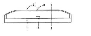
本実施例の衝突検知手段は、バンパリインフォースメント1、アブソーバ2、チャンバ部材3、圧力センサ4および演算手段(図示せず)と、から構成される。本実施例の衝突検知手段の構成を図1〜2に示した。なお、図1は、本実施例の衝突検知手段の上面図であり、図2は図1のI−I線における断面を示した図である。
Example 1
The collision detection means of the present embodiment includes a bumper reinforcement 1, an
バンパリインフォースメント1は、表面が車両の前方に対向した略帯状の金属板である。バンパリインフォースメント1は、帯の幅方向の中央部近傍10が車両の前方側に、両端部11,11が車両後方側に位置するように、テーパ部12,12が中央部近傍10と両端部11,11とを接続した断面凹字状に曲成された形状を有している。バンパリインフォースメント1は、帯ののびる方向が車両の幅方向にそった状態で、一対のフロントサイドメンバFmに固定される。バンパリインフォースメント1が固定される車両のフロントサイドメンバFmは、車両のエンジンルームの前方に突出した一対の部材である。
The bumper reinforcement 1 is a substantially strip-shaped metal plate whose surface faces the front of the vehicle. In the bumper reinforcement 1, the
アブソーバ2は、バンパリインフォースメント1に組み付けられる断面略コ字状に曲成された帯状の金属板である。アブソーバ2は、バンパリインフォースメント1のテーパ部12,12にスポット溶接で接合されている。アブソーバ2の帯状の長手方向の両端部も、バンパリインフォースメント1に接合された。つまり、アブソーバ2とバンパリインフォースメント1とは、密閉されていない閉じた空間が形成されている。
The
チャンバ部材3は、内部にチャンバ空間30を区画した略柱状の部材である。そして、この柱状の軸方向がアブソーバ2およびバンパリインフォースメント1ののびる方向にそった状態で、アブソーバ2とバンパリインフォースメント1とに区画された空間の内部に配置された。
The
圧力センサ4は、チャンバ部材3のチャンバ空間30の圧力を測定するためのセンサであり、チャンバ部材3に組み付けられている。
The
演算手段は、圧力センサ4に接続され、圧力センサ4の検出信号からチャンバ空間30の圧力を算出するとともに、算出された圧力から衝突の判定を行う。演算手段は、あらかじめ車両に搭載された演算手段としてもよい。好ましくは、乗員保護装置や歩行者保護装置の演算手段である。
The calculation means is connected to the
本実施例の衝突検知手段は、バンパリインフォースメント1をフロントサイドメンバFmにネジ止めにより固定し、その後、圧力センサ4を組み付けたチャンバ部材3を配置した状態でアブソーバ2をバンパリインフォースメント1に溶接で固定することで製造できる。
The collision detection means of this embodiment fixes the bumper reinforcement 1 to the front side member Fm by screwing, and then welds the
本実施例の衝突検知手段による衝突の検知について以下に説明する。 The collision detection by the collision detection means of the present embodiment will be described below.
本実施例の衝突検知手段が組み付けられた車両のバンパは、図3に示したように、バンパカバー5がアブソーバ2を被覆し、車両のバンパの外表面を形成している。
As shown in FIG. 3, the
この車両のバンパに衝突物が衝突すると、衝突物が車両のバンパを押圧することとなる。衝突物は、車両のバンパのバンパカバー5を介してアブソーバ2を押圧する。そして、アブソーバ2に加えられた応力(押圧力)が所定の大きさ以上であるときに、アブソーバ2は、車両の前後方向での距離(略コ字状の開口部と底面との距離)が短くなるように圧縮され、変形する。
When a collision object collides with the bumper of the vehicle, the collision object presses the bumper of the vehicle. The collision object presses the
この変形により、略コ字状の底面がチャンバ部材3を押圧し、チャンバ部材3が圧縮される。この圧縮により、チャンバ空間30の内部の圧力が上昇し、圧力センサ4が圧力の変化を測定し、演算手段が圧力の変化を検出する。そして、演算手段は、圧力の変化(上昇)から車両に衝突物が衝突したと判定する。また、演算手段は、圧力の変化の度合い(変化割合)から衝突物が歩行者等の人体あるいはそれに類するものであるか、他の車両など硬い構造物であるかを判定することもできる。このとき、演算手段には、車両の速度データも入力されたことが好ましい。
Due to this deformation, the substantially U-shaped bottom surface presses the
本実施例の衝突検知手段は、衝突の判定は、チャンバ部材3のチャンバ空間30の圧力変動にもとづいてなされている。つまり、アブソーバ2とバンパリインフォースメント1とにより区画される空間に気密性を要求していない。このため、アブソーバ2とバンパリインフォースメント1をスポット溶接で接合することで、製造に要するコストの上昇を抑えることができた。また、アブソーバ2とバンパリインフォースメント1の溶接箇所を少なくすることができ、溶接工程において生じるアブソーバ2のつぶれ特性の変化を抑えることができ、検出精度にすぐれた衝突検知手段となった。
In the collision detection means of this embodiment, the collision is determined based on the pressure fluctuation in the
また、本実施例の衝突検知手段においてチャンバ部材3は、アブソーバ2よりも軟質の材料より形成されている。このことは、衝突時に生じるアブソーバ2の変形をチャンバ部材3が規制しないことを示す。つまり、本実施例の衝突検知手段は、アブソーバ2のつぶれ特性を調節することで、歩行者衝突時における歩行者の脚部保護性能を満足する衝突特性を得ることができる効果を発揮する。
Further, in the collision detection means of the present embodiment, the
(実施例2)
本実施例の衝突検知手段は、車両のフロントサイドメンバFmに固定されたバンパリインフォースメント1、アブソーバ2、チャンバ部材3、圧力センサ4および演算手段(図示せず)と、から構成される。本実施例の衝突検知手段の構成を図4〜5に示した。なお、図4は、本実施例の衝突検知手段の上面図であり、図5は図4のII−II線における断面を示した図である。
(Example 2)
The collision detection means of the present embodiment includes a bumper reinforcement 1, an
車両のフロントサイドメンバFmおよびバンパリインフォースメント1は、実施例1の時と同様な部材である。 The front side member Fm and the bumper reinforcement 1 of the vehicle are the same members as in the first embodiment.
アブソーバ2は、バンパリインフォースメント1に組み付けられる断面略コ字状に曲成された帯状の金属板である。アブソーバ2は、バンパリインフォースメント1のテーパ部の表面にスポット溶接で接合された。アブソーバ2は、バンパリインフォースメント1に組み付けられた状態では、車両の幅方向(帯状の長手方向)の一方の端部側が開口し、他方の端部側が閉塞した有底筒状を形成している。
The
チャンバ部材3は、内部にチャンバ空間30を区画した略柱状の部材である。そして、この柱状の軸方向が車両の幅方向にそった状態となるように、アブソーバ2とバンパリインフォースメント1とに区画された空間の一方の端部から有底筒状の内部に挿入されて配置された。
The
圧力センサ4は、チャンバ部材3のチャンバ空間30の圧力を測定するためのセンサであり、チャンバ部材3に組み付けられた。
The
演算手段は、圧力センサ4に接続され、圧力センサ4の検出信号からチャンバ空間30の圧力を算出するとともに、算出された圧力から衝突の判定を行う。演算手段は、あらかじめ車両に搭載された演算手段としてもよい。好ましくは、乗員保護装置や歩行者保護装置の演算手段である。
The calculation means is connected to the
本実施例の衝突検知手段は、バンパリインフォースメント1をフロントサイドメンバFmにネジ止めで固定し、その後、アブソーバ2をバンパリインフォースメント1に溶接で固定した。そして、アブソーバ2とバンパリインフォースメント1とに区画された空間に一方の端部側から圧力センサ4を組み付けたチャンバ部材3を挿入して配置することで製造できる。
The collision detection means of this example fixed the bumper reinforcement 1 to the front side member Fm with screws, and then fixed the
本実施例の衝突検知手段は、製造方法が異なる以外の衝突の検知方法は実施例1と同様であり、実施例1の時と同様な効果を発揮する。 The collision detection means of this embodiment is the same as that of the first embodiment except for the manufacturing method, and the same effect as that of the first embodiment is exhibited.
さらに、本実施例の衝突検知手段は、アブソーバ2とバンパリインフォースメント1とを接合した後にチャンバ部材3を組み付けることから、チャンバ部材3の組付けを簡単に行うことができる効果を発揮した。
Furthermore, since the collision detection means of the present embodiment assembles the
1:バンパリインフォースメント 10:中央部近傍
11:両端部 12:テーパ部
2:アブソーバ 20:空間
3:チャンバ部材 30:チャンバ空間
4:圧力センサ
5:バンパーカバー
1: Bumper reinforcement 10: Near central portion 11: Both ends 12: Tapered portion 2: Absorber 20: Space 3: Chamber member 30: Chamber space 4: Pressure sensor 5: Bumper cover
Claims (12)
該裏板に一体に接合され、該裏板との間に空間を区画するアブソーバと、
該裏板と該アブソーバとの間に区画された該空間に配置された密閉されたチャンバ空間を区画するチャンバ部材と、
該チャンバ空間の圧力を検出する圧力センサと、
を有し、
該チャンバ部材が、該裏板と該アブソーバとに区画された該空間と略一致する外周形状を有し、
該チャンバ空間の圧力の変動から衝突を検知することを特徴とする衝突検知手段。 A back plate fixed to a side member of the vehicle;
An absorber that is integrally joined to the back plate and defines a space between the back plate;
A chamber member that defines a sealed chamber space disposed in the space defined between the back plate and the absorber;
A pressure sensor for detecting the pressure in the chamber space;
Have
The chamber member has an outer peripheral shape substantially coincident with the space partitioned by the back plate and the absorber;
A collision detection means for detecting a collision from fluctuations in pressure in the chamber space.
Priority Applications (3)
| Application Number | Priority Date | Filing Date | Title |
|---|---|---|---|
| JP2006085764A JP4626552B2 (en) | 2006-03-27 | 2006-03-27 | Collision detection means |
| DE102007006848A DE102007006848B4 (en) | 2006-03-27 | 2007-02-12 | Collision detection device |
| US11/728,594 US7637545B2 (en) | 2006-03-27 | 2007-03-26 | Collision detection apparatus |
Applications Claiming Priority (1)
| Application Number | Priority Date | Filing Date | Title |
|---|---|---|---|
| JP2006085764A JP4626552B2 (en) | 2006-03-27 | 2006-03-27 | Collision detection means |
Publications (2)
| Publication Number | Publication Date |
|---|---|
| JP2007261309A JP2007261309A (en) | 2007-10-11 |
| JP4626552B2 true JP4626552B2 (en) | 2011-02-09 |
Family
ID=38513587
Family Applications (1)
| Application Number | Title | Priority Date | Filing Date |
|---|---|---|---|
| JP2006085764A Expired - Fee Related JP4626552B2 (en) | 2006-03-27 | 2006-03-27 | Collision detection means |
Country Status (3)
| Country | Link |
|---|---|
| US (1) | US7637545B2 (en) |
| JP (1) | JP4626552B2 (en) |
| DE (1) | DE102007006848B4 (en) |
Families Citing this family (25)
| Publication number | Priority date | Publication date | Assignee | Title |
|---|---|---|---|---|
| JP5077639B2 (en) * | 2006-12-11 | 2012-11-21 | 株式会社デンソー | Pedestrian collision detection device and pedestrian protection system |
| JP4815387B2 (en) * | 2007-04-25 | 2011-11-16 | 株式会社イノアックコーポレーション | Shock absorbing member |
| JP4492823B2 (en) | 2007-06-19 | 2010-06-30 | 株式会社デンソー | Vehicle collision detection device |
| JP4264844B2 (en) * | 2007-06-21 | 2009-05-20 | 株式会社デンソー | Vehicle collision detection device |
| JP4403518B2 (en) * | 2007-07-13 | 2010-01-27 | 株式会社デンソー | Vehicle collision detection device |
| JP4375451B2 (en) | 2007-07-13 | 2009-12-02 | 株式会社デンソー | Vehicle collision detection device |
| JP4798459B2 (en) * | 2007-07-13 | 2011-10-19 | 株式会社デンソー | Vehicle collision detection device |
| JP4513833B2 (en) * | 2007-07-17 | 2010-07-28 | 株式会社デンソー | Vehicle collision detection device |
| JP4497182B2 (en) * | 2007-07-23 | 2010-07-07 | 株式会社デンソー | Collision detection device |
| JP5104347B2 (en) | 2008-01-30 | 2012-12-19 | 株式会社デンソー | Pedestrian collision detection device |
| JP4973950B2 (en) * | 2008-02-19 | 2012-07-11 | 株式会社デンソー | Collision detection device |
| JP2009220787A (en) * | 2008-03-18 | 2009-10-01 | Denso Corp | Collision detection device |
| JP4816665B2 (en) | 2008-03-18 | 2011-11-16 | 株式会社デンソー | Vehicle collision detection device |
| JP4692565B2 (en) * | 2008-03-21 | 2011-06-01 | トヨタ自動車株式会社 | Rear impact sensor mounting structure for vehicles |
| JP4941773B2 (en) * | 2008-03-27 | 2012-05-30 | 株式会社デンソー | Vehicle collision detection device |
| US8374751B2 (en) * | 2008-06-06 | 2013-02-12 | Chrysler Group Llc | Automotive impact sensing system |
| JP5041171B2 (en) * | 2008-09-17 | 2012-10-03 | 株式会社デンソー | Vehicle collision detection device |
| JP5302643B2 (en) * | 2008-12-02 | 2013-10-02 | 株式会社デンソー | Collision detection device and collision detection method |
| WO2011099206A1 (en) * | 2010-02-12 | 2011-08-18 | 本田技研工業株式会社 | Bumper structure for vehicle |
| US8398133B2 (en) | 2010-10-28 | 2013-03-19 | Ford Global Technologies, Llc | Pressure-based crash detection system incorporated in side rail |
| US9174595B2 (en) * | 2014-03-24 | 2015-11-03 | Ford Global Technologies, Llc | Collision sensing and energy absorbing apparatus |
| US9643554B2 (en) * | 2014-03-26 | 2017-05-09 | Ford Global Technologies, Llc | Collision sensing apparatus |
| JP6155228B2 (en) * | 2014-06-23 | 2017-06-28 | 本田技研工業株式会社 | Bumper beam structure of vehicle |
| DE102015213369A1 (en) * | 2015-07-16 | 2017-01-19 | Continental Automotive Gmbh | Elastic deformable hose with a cavity for a crash sensor in a motor vehicle |
| US10137850B2 (en) * | 2017-01-11 | 2018-11-27 | Toyota Motor Engineering & Manufacturing North America, Inc. | Vehicle bumper collision indicator |
Family Cites Families (11)
| Publication number | Priority date | Publication date | Assignee | Title |
|---|---|---|---|---|
| DE8433405U1 (en) * | 1985-05-02 | Schneider, Hans, Dipl.-Ing., 6393 Wehrheim | Bumper with integrated elastic bumper | |
| DE7302930U (en) * | 1972-03-07 | 1973-05-03 | Gulf & Western Ind Prod Co | Bumpers, in particular bumpers for vehicles |
| DE19728288A1 (en) * | 1997-07-02 | 1999-02-04 | Rudolf K Lobback | Vehicle bumper |
| JP4005255B2 (en) * | 1998-02-24 | 2007-11-07 | 株式会社豊田中央研究所 | Vehicle collision determination device |
| DE10114465B4 (en) * | 2001-03-24 | 2012-12-13 | Volkswagen Ag | Contact sensor and method for evaluating the signal of the contact sensor |
| DE10205398A1 (en) * | 2002-02-09 | 2003-08-21 | Bosch Gmbh Robert | Front sensor of a vehicle |
| JP2005521584A (en) * | 2002-03-28 | 2005-07-21 | オートリブ ディヴェロプメント アクチボラゲット | Collision detector system |
| DE10331862C5 (en) * | 2003-07-14 | 2016-04-14 | Volkswagen Ag | Vehicle frame protection element and method for controlling an occupant protection device |
| JP2005178416A (en) * | 2003-12-16 | 2005-07-07 | Toyota Motor Corp | Bumper structure for vehicles |
| JP4539281B2 (en) * | 2004-10-22 | 2010-09-08 | 株式会社デンソー | Obstacle discrimination device for vehicle |
| US7331415B2 (en) * | 2005-09-28 | 2008-02-19 | Delphi Technologies, Inc. | Pedestrian impact sensing apparatus for a vehicle bumper |
-
2006
- 2006-03-27 JP JP2006085764A patent/JP4626552B2/en not_active Expired - Fee Related
-
2007
- 2007-02-12 DE DE102007006848A patent/DE102007006848B4/en not_active Expired - Fee Related
- 2007-03-26 US US11/728,594 patent/US7637545B2/en not_active Expired - Fee Related
Also Published As
| Publication number | Publication date |
|---|---|
| US7637545B2 (en) | 2009-12-29 |
| DE102007006848B4 (en) | 2010-01-07 |
| DE102007006848A1 (en) | 2007-10-11 |
| US20070222236A1 (en) | 2007-09-27 |
| JP2007261309A (en) | 2007-10-11 |
Similar Documents
| Publication | Publication Date | Title |
|---|---|---|
| JP4626552B2 (en) | Collision detection means | |
| US8128140B2 (en) | Collision detecting device | |
| US8350685B2 (en) | Collision detecting device | |
| JP5011934B2 (en) | Collision detection means | |
| CN106029450B (en) | Vehicle bumper structure equipped with pedestrian collision detection sensor | |
| US8653958B2 (en) | Collision detection apparatus and method for same | |
| US10668881B2 (en) | Collision detection device for vehicle | |
| JP5360295B2 (en) | Pedestrian collision detection device | |
| US7911331B2 (en) | Collision detector | |
| JP6149742B2 (en) | Bumper structure for vehicles with pedestrian collision detection sensor | |
| JP2009023405A (en) | Collision detection sensor | |
| JP5962435B2 (en) | Bumper for vehicle equipped with pedestrian collision detection device | |
| JP4968514B2 (en) | Collision detection means | |
| JP2008201272A (en) | Collision detection means and protection system | |
| JP2017007368A (en) | Bumper structure for vehicles with pedestrian collision detection sensor | |
| US12325372B2 (en) | Collision detection apparatus | |
| US12391202B2 (en) | Contact detection apparatus for vehicle | |
| US12339189B2 (en) | Contact detection apparatus for vehicle | |
| JP5488932B2 (en) | Vehicle collision detection device | |
| JP4816187B2 (en) | Collision detection means | |
| JP2009220787A (en) | Collision detection device | |
| JP2000264142A (en) | Vehicle bumper structure | |
| JP4844819B2 (en) | Abnormality detection method for collision detection means | |
| JP5499907B2 (en) | Pedestrian collision detection device | |
| JP5429571B2 (en) | Vehicle collision detection device |
Legal Events
| Date | Code | Title | Description |
|---|---|---|---|
| A621 | Written request for application examination |
Free format text: JAPANESE INTERMEDIATE CODE: A621 Effective date: 20080508 |
|
| A131 | Notification of reasons for refusal |
Free format text: JAPANESE INTERMEDIATE CODE: A131 Effective date: 20100415 |
|
| A977 | Report on retrieval |
Free format text: JAPANESE INTERMEDIATE CODE: A971007 Effective date: 20100422 |
|
| A521 | Request for written amendment filed |
Free format text: JAPANESE INTERMEDIATE CODE: A523 Effective date: 20100610 |
|
| A131 | Notification of reasons for refusal |
Free format text: JAPANESE INTERMEDIATE CODE: A131 Effective date: 20100722 |
|
| A521 | Request for written amendment filed |
Free format text: JAPANESE INTERMEDIATE CODE: A523 Effective date: 20100915 |
|
| TRDD | Decision of grant or rejection written | ||
| A01 | Written decision to grant a patent or to grant a registration (utility model) |
Free format text: JAPANESE INTERMEDIATE CODE: A01 Effective date: 20101012 |
|
| A01 | Written decision to grant a patent or to grant a registration (utility model) |
Free format text: JAPANESE INTERMEDIATE CODE: A01 |
|
| A61 | First payment of annual fees (during grant procedure) |
Free format text: JAPANESE INTERMEDIATE CODE: A61 Effective date: 20101025 |
|
| FPAY | Renewal fee payment (event date is renewal date of database) |
Free format text: PAYMENT UNTIL: 20131119 Year of fee payment: 3 |
|
| FPAY | Renewal fee payment (event date is renewal date of database) |
Free format text: PAYMENT UNTIL: 20131119 Year of fee payment: 3 |
|
| R250 | Receipt of annual fees |
Free format text: JAPANESE INTERMEDIATE CODE: R250 |
|
| R250 | Receipt of annual fees |
Free format text: JAPANESE INTERMEDIATE CODE: R250 |
|
| R250 | Receipt of annual fees |
Free format text: JAPANESE INTERMEDIATE CODE: R250 |
|
| R250 | Receipt of annual fees |
Free format text: JAPANESE INTERMEDIATE CODE: R250 |
|
| LAPS | Cancellation because of no payment of annual fees |