JP4620089B2 - Game machine - Google Patents
Game machine Download PDFInfo
- Publication number
- JP4620089B2 JP4620089B2 JP2007202920A JP2007202920A JP4620089B2 JP 4620089 B2 JP4620089 B2 JP 4620089B2 JP 2007202920 A JP2007202920 A JP 2007202920A JP 2007202920 A JP2007202920 A JP 2007202920A JP 4620089 B2 JP4620089 B2 JP 4620089B2
- Authority
- JP
- Japan
- Prior art keywords
- value
- determination counter
- counter
- random
- predetermined
- Prior art date
- Legal status (The legal status is an assumption and is not a legal conclusion. Google has not performed a legal analysis and makes no representation as to the accuracy of the status listed.)
- Expired - Fee Related
Links
Images


Description
本発明は、パチンコ遊技機等の遊技機に関し、特に、遊技者の操作によって遊技が行われ、所定の条件が成立すると特定遊技を行うことが可能になって、特定遊技の結果が所定の態様になったことにもとづいて遊技者に所定の遊技価値が付与可能となる遊技機に関する。 The present invention relates to a gaming machine such as a pachinko gaming machine, and in particular, when a game is performed by a player's operation and a predetermined condition is satisfied, the specific game can be performed, and the result of the specific game is a predetermined mode. The present invention relates to a gaming machine that can give a predetermined game value to a player based on the fact that the game has been completed.
遊技機として、遊技球などの遊技媒体を発射装置によって遊技領域に発射し、遊技領域に設けられている入賞口などの入賞領域に遊技媒体が入賞すると、所定個の賞球が遊技者に払い出されるものがある。さらに、表示状態が変化可能な可変表示部が設けられ、可変表示部の表示結果があらかじめ定められた特定の表示態様となった場合に所定の遊技価値を遊技者に与えるように構成されたものがある。 As a gaming machine, a game medium such as a game ball is launched into a game area by a launching device, and when a game medium wins a prize area such as a prize opening provided in the game area, a predetermined number of prize balls are paid out to the player. There is something to be done. Further, a variable display unit capable of changing the display state is provided, and is configured to give a predetermined game value to the player when the display result of the variable display unit becomes a predetermined specific display mode There is.
可変表示部には複数の表示領域があり、通常、複数の可変表示の表示結果を時期を異ならせて表示するように構成されている。可変表示部には、例えば、図柄等の複数の識別情報が可変表示される。可変表示部の表示結果があらかじめ定められた特定の表示態様の組合せとなることを、通常、「大当り」という。なお、遊技価値とは、遊技機の遊技領域に設けられた可変入賞球装置の状態が打球が入賞しやすい遊技者にとって有利な状態になることや、遊技者にとって有利な状態となるための権利を発生させたりすることである。「大当り」が発生すると、例えば、遊技者に大量の賞球などの価値が払い出される。 The variable display section has a plurality of display areas, and is usually configured to display the display results of the plurality of variable displays at different times. For example, a plurality of pieces of identification information such as symbols are variably displayed on the variable display section. That the display result of the variable display unit is a combination of specific display modes determined in advance is usually called “big hit”. Note that the game value is the right that the state of the variable winning ball device provided in the gaming area of the gaming machine is advantageous for a player who is likely to win a ball, or the advantageous state for a player. It is to generate. When a “hit” occurs, for example, a player is given a value such as a large number of prize balls.
そのような遊技機における遊技制御においては、所定の条件(例えば可変表示開始の条件となる始動入賞)が成立すると乱数を発生させ、乱数値があらかじめ決まられている所定値と一致すると「大当り」となる。また、ノイズ対策等の理由によって遊技制御を行う回路部分は、所定の時間間隔(例えば2ms)でリセットされ再起動される。乱数値は所定のカウンタを用いて生成され、カウンタ値の更新は遊技制御を行う回路部分において行われているので、発生される乱数の値は、遊技制御を行う回路部分の起動の時間間隔に同期せざるを得ない。 In game control in such a gaming machine, a random number is generated when a predetermined condition (for example, a start prize that becomes a variable display start condition) is satisfied, and a “big hit” when the random number value matches a predetermined value. It becomes. In addition, a circuit portion that performs game control for reasons such as noise countermeasures is reset and restarted at a predetermined time interval (for example, 2 ms). Since the random number value is generated using a predetermined counter, and the update of the counter value is performed in the circuit portion that performs the game control, the generated random number value is the time interval of activation of the circuit portion that performs the game control. I have to synchronize.
すると、何らかの手段で起動の時間間隔が検出されると、カウンタ値更新タイミングが認識されてしまう。さらに、「大当り」となる乱数値が発生するタイミングが認識されてしまう。すると、「大当り」となる乱数値が発生するタイミングで始動入賞を狙うことによって、頻繁に「大当り」を発生させることが可能になってしまう。 Then, when the activation time interval is detected by some means, the counter value update timing is recognized. Furthermore, the timing at which a random value that is a “big hit” is recognized is recognized. Then, it becomes possible to frequently generate a “hit” by aiming for a start winning prize at a timing when a random value that becomes a “hit” is generated.
遊技制御を行う回路部分の起動タイミングを検出するために、遊技機に不正基板が取り付けられる場合がある。そのような不正基板は遊技制御を行う回路部分から外部に出力される信号を導入し、その信号にもとづいて遊技制御を行う回路部分の起動タイミングを検出し、「大当り」を生じさせる乱数値が発生するタイミングを検出している。そして、不正基板は、そのタイミングで遊技制御を行う回路部分に始動入賞信号を送り「大当り」を不正に発生させることが可能になる。 An illegal board may be attached to the gaming machine in order to detect the start timing of the circuit portion that performs game control. Such a fraudulent board introduces a signal output to the outside from the circuit part that performs game control, detects the activation timing of the circuit part that performs game control based on the signal, and generates a random number value that causes a “hit” The timing of occurrence is detected. Then, the illegal board can illegally generate a “hit” by sending a start winning signal to the circuit portion that controls the game at that timing.
例えば、可変表示部の表示状態を制御する表示制御用マイクロコンピュータが搭載された表示制御基板には、遊技制御を行う回路が搭載された主基板から、表示状態を変化させるために表示制御コマンドが送出される。上述したように、遊技制御を行う回路部分は例えば2ms毎にリセットされるので、表示制御コマンドの送出間隔は、2msに同期する。不正基板が主基板と表示制御基板との間に接続され、かつ、例えば本来の始動入賞信号を導入し、表示制御コマンドの送出間隔にもとづいてカウンタ値更新タイミングを認識した上で、「大当り」を生じさせる乱数値の発生をねらって不正な始動入賞信号を主基板に送り込めば、不正に「大当り」が発生することになる。 For example, a display control board on which a display control microcomputer for controlling the display state of the variable display unit is mounted has a display control command for changing the display state from a main board on which a circuit for performing game control is mounted. Sent out. As described above, the circuit portion that performs game control is reset every 2 ms, for example, and therefore the display control command transmission interval is synchronized with 2 ms. A "big hit" is made after an illegal board is connected between the main board and the display control board, and the counter value update timing is recognized based on the display control command sending interval, for example, by introducing an original start winning signal. If an illegal start winning signal is sent to the main board in order to generate a random number value that will cause a "big hit", an illegal "big hit" will occur.
遊技機には、可変表示装置、装飾ランプ、音発生機器などの各種部品が存在するので、遊技制御を行う回路部分からそれらの部品に至る信号線をなくすことはできない。従って、上述したような不正基板が取り付けられ不正遊技行為が行われる余地がどうしても残る。よって、不正基板を用いた不正遊技行為をいかに防ぐかは遊技機における重要な課題になっている。 Since various components such as a variable display device, a decorative lamp, and a sound generator are present in the gaming machine, it is not possible to eliminate signal lines from the circuit portion that performs game control to those components. Accordingly, there remains a room where the illegal board as described above is attached and illegal gaming acts are performed. Therefore, how to prevent an illegal gaming act using an illegal board is an important issue in the gaming machine.
そこで、本発明は、不正基板による遊技に対する攻撃を効果的に防御できる遊技機を提供することを目的とする。 In view of the above, an object of the present invention is to provide a gaming machine that can effectively prevent an attack against a game by an unauthorized board.
本発明による遊技機は、遊技者の操作にもとづいて遊技を行うとともに遊技者に有利となる特定遊技状態に移行可能な遊技機であって、所定の数値範囲内で特定遊技判定用カウンタの値を更新する特定遊技判定用カウンタ更新手段と、所定の条件が成立すると特定遊技判定用カウンタの値を抽出し抽出値と判定値とを比較してそれらが一致すると特定遊技状態に移行させる遊技制御手段と、特定遊技判定用カウンタの更新初期値を決定するための初期値決定用カウンタの値を更新する初期値決定用カウンタ更新手段と、特定遊技判定用カウンタの値が所定値になったことを条件に初期値決定用カウンタの値を抽出して特定遊技判定用カウンタが所定周回するまで記憶しておくとともに、該記憶した初期値決定用カウンタの値にもとづいて特定遊技判定用カウンタが所定周回したときに特定遊技判定用カウンタに初期値を設定する初期値更新手段と、初期値決定用カウンタの値が抽出されるタイミングとなる所定値を決定するための数値決定手段とを備え、初期値更新手段は、記憶した初期値決定用カウンタの値を用いて演算処理を行い演算結果を初期値として特定遊技判定用カウンタに設定し、数値決定手段は、初期値決定用カウンタとは別のカウンタを初期値決定用カウンタとは別の更新条件で更新する手段であって、特定遊技判定用カウンタと同じ数値範囲内で所定値決定用カウンタの値を更新する所定値決定用カウンタ更新手段と、特定遊技判定用カウンタが所定周回したときに所定値決定用カウンタの値を抽出し、該抽出した値を所定値として記憶する抽出記憶手段とを備えたものである。 A gaming machine according to the present invention is a gaming machine that is capable of playing a game based on a player's operation and being able to shift to a specific gaming state that is advantageous to the player, the value of a specific game determination counter within a predetermined numerical range Specific game determination counter update means for updating the game, and a game control for extracting the value of the specific game determination counter when a predetermined condition is satisfied, comparing the extracted value with the determination value, and shifting to the specific game state when they match Means, initial value determination counter updating means for updating the value of the initial value determination counter for determining the initial update value of the specific game determination counter, and the value of the specific game determination counter has become a predetermined value. with extracts the value of the initial value determination counter specific game determining counter stored until a predetermined orbit in a condition, identified based on the value of the initial value determination counter to the storage Numerology for determining an initial value updating means skill determination counter is set to an initial value to a specific game determining counter when a predetermined orbit, a predetermined value which is a timing at which the value of the initial value determination counter is extracted The initial value update means performs an arithmetic process using the stored initial value determination counter value, sets the calculation result as an initial value in the specific game determination counter, and the numerical value determination means determines the initial value determination Is a means for updating a counter different from the counter for use with an update condition different from that for the initial value determination counter, and a predetermined value for updating the value of the predetermined value determination counter within the same numerical range as the specific game determination counter A determination counter updating means; and an extraction storage means for extracting the value of the predetermined value determination counter when the specific game determination counter makes a predetermined number of revolutions and storing the extracted value as a predetermined value. Those were.
本発明によれば、遊技機を、特定遊技判定用カウンタの値が所定値になったことを条件に初期値決定用カウンタの値を抽出して特定遊技判定用カウンタが所定周回するまで記憶しておくとともに、該記憶した初期値決定用カウンタの値にもとづいて特定遊技判定用カウンタが所定周回したときに特定遊技判定用カウンタに初期値を設定する初期値更新手段を備え、初期値更新手段が、記憶した初期値決定用カウンタの値を用いて演算処理を行い演算結果を初期値として特定遊技判定用カウンタに設定するように構成にしたので、所定の起動タイミングに同期して遊技制御手段から出力される各種信号を観測しても、特定遊技判定用の数値が判定値と一致するタイミングを推測することはできなくなり、その結果、外部から大当りを不正に発生させるための信号を与えることができなくなって、不正遊技行為を効果的に防止できる効果がある。 According to the present invention, the gaming machine stores the value of the initial value determination counter on the condition that the value of the specific game determination counter reaches a predetermined value and stores the value until the specific game determination counter makes a predetermined number of laps. And initial value updating means for setting an initial value in the specific game determination counter when the specific game determination counter makes a predetermined number of turns based on the stored initial value determination counter value. However, since it is configured to perform arithmetic processing using the stored initial value determination counter value and set the arithmetic result as the initial value in the specific game determination counter, the game control means is synchronized with a predetermined activation timing. Observing the various signals output from the game, it is no longer possible to guess when the numerical value for the specific game decision matches the decision value, resulting in illegal jackpots from the outside Signal no longer can give for an effect of effectively preventing illegal gaming activities.
以下、本発明の一実施形態を図面を参照して説明する。
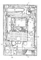
まず、遊技機の一例であるパチンコ遊技機の全体の構成について説明する。図1はパチンコ遊技機1を正面からみた正面図、図2はパチンコ遊技機1の内部構造を示す全体背面図、図3はパチンコ遊技機1の遊技盤を背面からみた背面図である。なお、ここでは、遊技機の一例としてパチンコ遊技機を示すが、本発明はパチンコ遊技機に限られず、例えばコイン遊技機等であってもよい。
Hereinafter, an embodiment of the present invention will be described with reference to the drawings.
First, the overall configuration of a pachinko gaming machine that is an example of a gaming machine will be described. 1 is a front view of the
図1に示すように、パチンコ遊技機1は、額縁状に形成されたガラス扉枠2を有する。ガラス扉枠2の下部表面には打球供給皿3がある。打球供給皿3の下部には、打球供給皿3からあふれた景品玉を貯留する余剰玉受皿4と打球を発射する打球操作ハンドル(操作ノブ)5が設けられている。ガラス扉枠2の後方には、遊技盤6が着脱可能に取り付けられている。また、遊技盤6の前面には遊技領域7が設けられている。
As shown in FIG. 1, the
遊技領域7の中央付近には、複数種類の図柄を可変表示するための可変表示部9と7セグメントLEDによる可変表示器10とを含む可変表示装置8が設けられている。この実施の形態では、可変表示部9には、「左」、「中」、「右」の3つの図柄表示エリアがある。可変表示装置8の側部には、打球を導く通過ゲート11が設けられている。通過ゲート11を通過した打球は、玉出口13を経て始動入賞口14の方に導かれる。通過ゲート11と玉出口13との間の通路には、通過ゲート11を通過した打球を検出するゲートスイッチ12がある。また、始動入賞口14に入った入賞球は、遊技盤6の背面に導かれ、始動口スイッチ17によって検出される。また、始動入賞口14の下部には開閉動作を行う可変入賞球装置15が設けられている。可変入賞球装置15は、ソレノイド16によって開状態とされる。
Near the center of the
可変入賞球装置15の下部には、特定遊技状態(大当り状態)においてソレノイド21によって開状態とされる開閉板20が設けられている。この実施の形態では、開閉板20が大入賞口を開閉する手段となる。開閉板20から遊技盤6の背面に導かれた入賞球のうち一方(Vゾーン)に入った入賞球はVカウントスイッチ22で検出される。また、開閉板20からの入賞球はカウントスイッチ23で検出される。可変表示装置8の下部には、始動入賞口14に入った入賞球数を表示する4個の表示部を有する始動入賞記憶表示器18が設けられている。この例では、4個を上限として、始動入賞がある毎に、始動入賞記憶表示器18は点灯している表示部を1つずつ増やす。そして、可変表示部9の可変表示が開始される毎に、点灯している表示部を1つ減らす。
An open /
遊技盤6には、複数の入賞口19,24が設けられている。遊技領域7の左右周辺には、遊技中に点滅表示される装飾ランプ25が設けられ、下部には、入賞しなかった打球を吸収するアウト口26がある。また、遊技領域7の外側の左右上部には、効果音を発する2つのスピーカ27が設けられている。遊技領域7の外周には、遊技効果LED28aおよび遊技効果ランプ28b,28cが設けられている。
The
そして、この例では、一方のスピーカ27の近傍に、景品玉払出時に点灯する賞球ランプ51が設けられ、他方のスピーカ27の近傍に、補給玉が切れたときに点灯する球切れランプ52が設けられている。さらに、図1には、パチンコ遊技台1に隣接して設置され、プリペイドカードが挿入されることによって球貸しを可能にするカードユニット50も示されている。
In this example, a
カードユニット50には、使用可能状態であるか否かを示す使用可表示ランプ151、カード内に記録された残額情報に端数(100円未満の数)が存在する場合にその端数を打球供給皿3の近傍に設けられる度数表示LEDに表示させるための端数表示スイッチ152、カードユニット50がいずれの側のパチンコ遊技機1に対応しているのかを示す連結台方向表示器153、カードユニット50内にカードが投入されていることを示すカード投入表示ランプ154、記録媒体としてのカードが挿入されるカード挿入口155、およびカード挿入口155の裏面に設けられているカードリーダライタの機構を点検する場合にカードユニット50を解放するためのカードユニット錠156が設けられている。
The
打球発射装置から発射された打球は、打球レールを通って遊技領域7に入り、その後、遊技領域7を下りてくる。打球が通過ゲート11を通ってゲートスイッチ12で検出されると、可変表示器10の表示数字が連続的に変化する状態になる。また、打球が始動入賞口14に入り始動口スイッチ17で検出されると、図柄の変動を開始できる状態であれば、可変表示部9内の図柄が回転を始める。図柄の変動を開始できる状態でなければ、始動入賞記憶を1増やす。なお、始動入賞記憶については、後で詳しく説明する。
The hit ball fired from the hit ball launching device enters the
可変表示部9内の画像の回転は、一定時間が経過したときに停止する。停止時の画像の組み合わせが大当り図柄の組み合わせであると、大当り遊技状態に移行する。すなわち、開閉板20が、一定時間経過するまで、または、所定個数(例えば10個)の打球が入賞するまで開放する。そして、開閉板20の開放中に打球が特定入賞領域に入賞しVカウントスイッチ22で検出されると、継続権が発生し開閉板20の開放が再度行われる。継続権の発生は、所定回数(例えば15ラウンド)許容される。
The rotation of the image in the
停止時の可変表示部9内の画像の組み合わせが確率変動を伴う大当り図柄の組み合わせである場合には、次に大当りとなる確率が高くなる。すなわち、高確率状態という遊技者にとってさらに有利な状態となる。
また、可変表示器10における停止図柄が所定の図柄(当り図柄)である場合に、可変入賞球装置15が所定時間だけ開状態になる。さらに、高確率状態では、可変表示器10における停止図柄が当り図柄になる確率が高められるとともに、可変入賞球装置15の開放時間と開放回数が高められる。
When the combination of images in the
Further, when the stop symbol on the
次に、パチンコ遊技機1の裏面の構造について図2を参照して説明する。
可変表示装置8の背面では、図2に示すように、機構板36の上部に景品玉タンク38が設けられ、パチンコ遊技機1が遊技機設置島に設置された状態でその上方から景品玉が景品玉タンク38に供給される。景品玉タンク38内の景品玉は、誘導樋39を通って玉払出装置に至る。
Next, the structure of the back surface of the
On the back surface of the
機構板36には、中継基板30を介して可変表示部9を制御する可変表示制御ユニット29、基板ケース32に覆われ遊技制御用マイクロコンピュータ等が搭載された遊技制御基板(主基板)31、可変表示制御ユニット29と遊技制御基板31との間の信号を中継するための中継基板33、および景品玉の払出制御を行う賞球制御用マイクロコンピュータ等が搭載された賞球制御基板37が設置されている。さらに、機構板36には、モータの回転力を利用して打球を遊技領域7に発射する打球発射装置34と、遊技効果ランプ・LED28a,28b,28c、賞球ランプ51および球切れランプ52に信号を送るためのランプ制御基板35が設置されている。
The
また、図3はパチンコ遊技機1の遊技盤を背面からみた背面図である。遊技盤6の裏面には、図3に示すように、各入賞口および入賞球装置に入賞した入賞玉を所定の入賞経路に沿って導く入賞玉集合カバー40が設けられている。入賞玉集合カバー40に導かれる入賞玉のうち、開閉板20を経て入賞したものは、玉払出装置(図3において図示せず)が相対的に多い景品玉数(例えば15個)を払い出すように制御される。始動入賞口14を経て入賞したものは、玉払出装置が相対的に少ない景品玉数(例えば6個)を払い出すように制御される。そして、その他の入賞口24および入賞球装置を経て入賞したものは、玉払出装置が相対的に中程度の景品玉数(例えば10個)を払い出すように制御される。なお、図3には、中継基板33が例示されている。
FIG. 3 is a rear view of the game board of the
賞球払出制御を行うために、入賞球検出スイッチ99、始動口スイッチ17およびVカウントスイッチ22からの信号が、主基板31に送られる。入賞があったことは入賞球検出スイッチ99で検出されるが、主基板31に入賞球検出スイッチ99のオン信号が送られると、主基板31から賞球制御基板37に賞球制御コマンドが送られる。例えば、始動口スイッチ17のオンに対応して入賞球検出スイッチ99がオンすると、賞球個数「6」を示す賞球制御コマンドが出力され、カウントスイッチ23またはVカウントスイッチ22のオンに対応して入賞球検出スイッチ99がオンすると、賞球個数「15」を示す賞球制御コマンドが出力される。そして、それらのスイッチがオンしない場合に入賞球検出スイッチ99がオンすると、賞球個数「10」を示す賞球制御コマンドが出力される。
In order to perform the winning ball payout control, signals from the winning
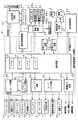
図4は、主基板31における回路構成の一例を示すブロック図である。なお、図4には、賞球制御基板37、ランプ制御基板35、音声制御基板70、発射制御基板91および表示制御基板80も示されている。主基板31には、プログラムに従ってパチンコ遊技機1を制御する基本回路53と、ゲートスイッチ12、始動口スイッチ17、Vカウントスイッチ22、カウントスイッチ23および入賞球検出スイッチ99からの信号を基本回路53に与えるスイッチ回路58と、可変入賞球装置15を開閉するソレノイド16および開閉板20を開閉するソレノイド21を基本回路53からの指令に従って駆動するソレノイド回路59と、始動記憶表示器18の点灯および滅灯を行うとともに7セグメントLEDによる可変表示器10と装飾ランプ25とを駆動するランプ・LED回路60とを含む。
FIG. 4 is a block diagram illustrating an example of a circuit configuration in the main board 31. FIG. 4 also shows a prize
また、基本回路53から与えられるデータに従って、大当りの発生を示す大当り情報、可変表示部9の画像表示開始に利用された始動入賞球の個数を示す有効始動情報、確率変動が生じたことを示す確変情報等をホール管理コンピュータ等のホストコンピュータに対して出力する情報出力回路64を含む。
Further, according to the data given from the
基本回路53は、ゲーム制御用のプログラム等を記憶するROM54、ワークメモリとして使用されるRAM55、制御用のプログラムに従って制御動作を行うCPU56およびI/Oポート部57を含む。なお、ROM54,RAM55はCPU56に内蔵されている場合もある。
The
さらに、主基板31には、電源投入時に基本回路53をリセットするための初期リセット回路65と、定期的(例えば、2ms毎)に基本回路53にリセットパルスを与えてゲーム制御用のプログラムを先頭から再度実行させるための定期リセット回路66と、基本回路53から与えられるアドレス信号をデコードしてI/Oポート部57のうちのいずれかのI/Oポートを選択するための信号を出力するアドレスデコード回路67とが設けられている。
なお、玉払出装置97から主基板31に入力されるスイッチ情報もあるが、図4ではそれらは省略されている。
Further, an initial reset circuit 65 for resetting the
Note that there is also switch information input to the main board 31 from the ball dispensing device 97, but these are omitted in FIG.
遊技球を打撃して発射する打球発射装置は発射制御基板91上の回路によって制御される駆動モータ94で駆動される。そして、駆動モータ94の駆動力は、操作ノブ5の操作量に従って調整される。すなわち、発射制御基板91上の回路によって、操作ノブ5の操作量に応じた速度で打球が発射されるように制御される。
A ball hitting device for hitting and launching a game ball is driven by a drive motor 94 controlled by a circuit on the
次に動作について説明する。
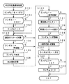
図5は、主基板31におけるCPU56が実行する遊技制御プログラムのメイン動作を示すフローチャートである。上述したように、この処理は、定期リセット回路66が発するリセットパルスによって、例えば2ms毎に起動される。CPU56が起動されると、CPU56は、まず、クロックモニタ制御を動作可能状態にするために、CPU56に内蔵されているクロックモニタレジスタをクロックモニタイネーブル状態に設定する(ステップS1)。なお、クロックモニタ制御とは、入力されるクロック信号の低下または停止を検出すると、CPU56の内部で自動的にリセットを発生する制御である。
Next, the operation will be described.
FIG. 5 is a flowchart showing the main operation of the game control program executed by the CPU 56 on the main board 31. As described above, this processing is started, for example, every 2 ms by a reset pulse generated by the periodic reset circuit 66. When the CPU 56 is activated, the CPU 56 first sets a clock monitor register built in the CPU 56 to a clock monitor enable state in order to enable clock monitor control (step S1). Note that the clock monitor control is a control that automatically generates a reset within the CPU 56 when a drop or stop of the input clock signal is detected.
次いで、CPU56は、スタックポインタの指定アドレスをセットするためのスタックセット処理を行う(ステップS2)。この例では、スタックポインタに00FFHが設定される。そして、システムチェック処理を行う(ステップS3)。システムチェック処理では、CPU56は、RAM55にエラーが含まれているか判定し、エラーが含まれている場合には、RAM55を初期化するなどの処理を行う。
Next, the CPU 56 performs a stack setting process for setting the designated address of the stack pointer (step S2). In this example, 00FFH is set in the stack pointer. Then, a system check process is performed (step S3). In the system check process, the CPU 56 determines whether or not an error is included in the
次に、表示制御基板80に送出される表示制御コマンドをRAM55の所定の領域に設定する処理を行った後に(表示制御データ設定処理:ステップS4)、表示制御コマンドを出力する処理を行う(表示制御データ伝送処理:ステップS5)。
Next, after performing a process of setting a display control command sent to the
次いで、各種出力データの格納領域の内容を各出力ポートに出力する処理を行う(データ出力処理:ステップS6)。また、各種出力データの格納領域の出力データを設定するとともに、ホール管理用コンピュータに出力される大当り情報、始動情報、確率変動情報などの出力データを格納領域に設定する出力データ設定処理を行う(ステップS8)。さらに、パチンコ遊技機1の内部に備えられている自己診断機能によって種々の異常診断処理が行われ、その結果に応じて必要ならば警報が発せられる(エラー処理:ステップS9)。
Next, a process of outputting the contents of the storage area for various output data to each output port is performed (data output process: step S6). In addition to setting output data in the storage area for various output data, an output data setting process for setting output data such as jackpot information, starting information, probability variation information, etc., output to the hall management computer to the storage area is performed ( Step S8). Further, various abnormality diagnosis processes are performed by the self-diagnosis function provided in the
次に、遊技制御に用いられる大当り判定用の乱数等の各判定用乱数を生成するための各カウンタを更新する処理を行う(ステップS10)。
図6は、各乱数を示す説明図である。各乱数は、以下のように使用される。
(1)ランダム1:大当りを発生させるか否か決定する(大当り判定用)
(2)ランダム2−1〜2−3:左右中のはずれ図柄決定用
(3)ランダム3:大当り時の図柄の組合せを決定する(大当り図柄決定用=特定図柄判定用)
(4)ランダム4:はずれ時にリーチするか否か決定する(リーチ判定用)
(5)ランダム5:リーチ種類を決定する(リーチ動作決定用)
(6)ランダム6:ランダム1を生成するためのカウンタの初期値を決定する(ランダム1初期値決定用)
Next, a process of updating each counter for generating each determination random number such as a big hit determination random number used for game control is performed (step S10).
FIG. 6 is an explanatory diagram showing each random number. Each random number is used as follows.
(1) Random 1: Decide whether or not to generate a big hit (for big hit judgment)
(2) Random 2-1-2-3: For left / right centered symbol determination (3) Random 3: Determines the symbol combination at the time of jackpot (for jackpot symbol determination = for specific symbol determination)
(4) Random 4: Decide whether or not to reach when falling off (for reach determination)
(5) Random 5: Reach type is determined (for reaching operation determination)
(6) Random 6: Determines the initial value of the counter for generating random 1 (for determining random 1 initial value)
ここで、ランダム6は、ランダム1を生成するためのカウンタ値が所定回周回したらランダム1を生成するためのカウンタに新たに設定される値を決定するための乱数である。なお、図6に示された各乱数の範囲は一例であるが、図6に示された乱数範囲とは異なる範囲を用いる場合でも、ランダム6のとりうる範囲はランダム1のとりうる範囲と同じに設定される。 Here, random 6 is a random number for determining a value newly set in the counter for generating random 1 when the counter value for generating random 1 circulates a predetermined number of times. The range of each random number shown in FIG. 6 is an example, but even when a range different from the random number range shown in FIG. 6 is used, the range that random 6 can take is the same as the range that random 1 can take. Set to
なお、遊技効果を高めるために、上記(1)〜(6)の乱数以外の乱数も用いられている。また、可変表示部9には、遊技効果を高めるために、各図柄以外の画像、例えば背景や所定の動きをするキャラクタ等も表示される。
ステップS10では、CPU56は、(1)の大当り判定用乱数および(3)の大当り図柄判定用乱数を生成するためのカウンタのカウントアップ(1加算)を行う。
In order to enhance the game effect, random numbers other than the random numbers (1) to (6) are also used. In addition, in order to enhance the gaming effect, the
In step S10, the CPU 56 counts up (adds 1) a counter for generating the jackpot determination random number (1) and the jackpot symbol determination random number (3).
次に、CPU56は、特別図柄プロセス処理を行う(ステップS11)。特別図柄プロセス制御では、遊技状態に応じてパチンコ遊技機1を所定の順序で制御するための特別図柄プロセスフラグに従って該当する処理が選び出されて実行される。そして、特別図柄プロセスフラグの値は、遊技状態に応じて各処理中に更新される。また、普通図柄プロセス処理を行う(ステップS12)。普通図柄プロセス処理では、7セグメントLEDによる可変表示器10を所定の順序で制御するための普通図柄プロセスフラグに従って該当する処理が選び出されて実行される。そして、普通図柄プロセスフラグの値は、遊技状態に応じて各処理中に更新される。
Next, the CPU 56 performs special symbol process processing (step S11). In the special symbol process control, corresponding processing is selected and executed according to a special symbol process flag for controlling the
さらに、CPU56は、スイッチ回路58を介して、ゲートセンサ12、始動口センサ17およびカウントセンサ23の状態を入力し、各入賞口や入賞装置に対する入賞があったか否か判定する(スイッチ処理:ステップS13)。
Further, the CPU 56 inputs the states of the gate sensor 12, the
CPU56は、さらに、表示用乱数を生成するための各カウンタを更新する処理を行う(ステップS15)。すなわち、(2)のはずれ図柄決定用の乱数、(4)のリーチ判定用の乱数および(5)のリーチ動作用の乱数を生成するカウンタのカウントアップ(1加算)を行う。ただし、ランダム2−2は、ランダム2−1の桁上げが生ずるときに、すなわち、ランダム2−1の値が「15」になって「0」に戻されるときにカウントアップされる。また、ランダム2−3は、ランダム2−2の桁上げが生ずるときに、すなわち、ランダム2−2の値が「15」になって「0」に戻されるときにカウントアップされる。 The CPU 56 further performs a process of updating each counter for generating a display random number (step S15). In other words, the counter for generating the random symbol for determining the symbol of (2), the random number for determining the reach of (4), and the random number for the reaching operation of (5) is incremented (added by 1). However, the random 2-2 is counted up when the carry of the random 2-1 occurs, that is, when the value of the random 2-1 becomes “15” and is returned to “0”. Random 2-3 is counted up when a carry of random 2-2 occurs, that is, when the value of random 2-2 becomes “15” and returns to “0”.
そして、ランダム1初期値決定用乱数を更新する処理を行う(ステップS16)。すなわち、ランダム1初期値決定用乱数を生成するためのカウンタを+1する。 And the process which updates the random number for random 1 initial value determination is performed (step S16). That is, the counter for generating the random 1 initial value determining random number is incremented by one.
また、CPU56は、賞球制御基板37との間の入賞球信号処理を行う(ステップS17)。すなわち、所定の条件が成立すると賞球制御基板37に賞球個数信号を出力する。賞球制御基板37に搭載されている賞球制御用CPUは、賞球個数信号に応じて玉払出装置97を駆動する。
Further, the CPU 56 performs a winning ball signal process with the winning ball control board 37 (step S17). That is, when a predetermined condition is satisfied, a prize ball number signal is output to the prize
その後、CPU56は、次に定期リセット回路66からリセットパルスが与えられるまで、すなわち、無限ループで、ステップS18の表示用乱数更新処理(+1する処理)およびステップS19のランダム1初期値決定用乱数更新処理を繰り返す。ステップS1〜S17に要する時間は2msよりも短いので、2msに達するまでの余り時間で、表示用乱数更新処理およびランダム1初期値決定用カウンタの更新処理が繰り返し実行される。なお、遊技状況が異なるとステップS1〜S17に要する時間も異なってくるので、余り時間は一定時間ではない。また、ステップS18の表示用乱数更新処理の内容はステップS15の処理と同じであり、ステップS19のランダム1初期値決定用乱数更新処理の内容はステップS16の処理と同じである。 Thereafter, until the next reset pulse is supplied from the periodic reset circuit 66, that is, in an infinite loop, the CPU 56 performs a random number update process for displaying (adding +1) in step S18 and a random random number for determining a random 1 initial value in step S19. Repeat the process. Since the time required for steps S1 to S17 is shorter than 2 ms, the display random number update process and the random 1 initial value determination counter update process are repeatedly executed with the remaining time until reaching 2 ms. Note that the time required for steps S1 to S17 differs depending on the game situation, so the surplus time is not a fixed time. Further, the content of the display random number update process in step S18 is the same as the process in step S15, and the content of the random 1 initial value determination random number update process in step S19 is the same as the process in step S16.
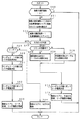
次に、始動入賞口14への入賞(始動入賞)にもとづいて可変表示部9に可変表示される図柄の決定方法について図7〜図9のフローチャートを参照して説明する。図7は打球が始動入賞口14に入賞したことを判定する処理を示し、図8は図柄を決定する処理を示し、図9は大当り判定の処理を示す。なお、図7〜図9に示す処理は、図5に示されたメイン処理における特別図柄プロセス処理(ステップS11)において実行される。
Next, a method of determining a symbol variably displayed on the
打球が遊技盤6に設けられている始動入賞口14に入賞すると、始動口スイッチ17がオンする。CPU56は、スイッチ回路58およびI/Oポート57を介して始動口スイッチ17がオンしたことを検出すると(ステップS41)、始動入賞記憶数が始動記憶上限値に達しているかどうか確認する(ステップS42)。始動入賞記憶数が始動記憶上限値に達していなければ、始動入賞記憶数を1増やす(ステップS43)。なお、この実施の形態では、始動記憶上限値は4である。
When the hit ball wins the
そして、ランダム1を生成するためのカウンタの値を抽出し、抽出値を、各始動入賞記憶数n(n=1,2,3,・・・,始動記憶上限値)に対応して設けられている乱数値格納エリアに格納する(ステップS44)。なお、始動入賞記憶数が始動記憶上限値に達している場合には、ステップS43〜S44の処理を行わない。 And the value of the counter for generating random 1 is extracted, and the extracted value is provided corresponding to each start winning memory number n (n = 1, 2, 3,..., Start memory upper limit value). Stored in the stored random value storage area (step S44). Note that if the start winning memory number has reached the start memory upper limit value, the processing of steps S43 to S44 is not performed.
CPU56は、画像表示部9の可変表示を開始できる状態になると図8のフローチャートに示す処理を行う。
まず、始動入賞記憶数の値を確認する(ステップS50)。始動入賞記憶数が0でなければ、始動入賞記憶数=1に対応する乱数値格納エリアに格納されている値を読み出すとともに(ステップS51)、始動入賞記憶数の値を1減らし、かつ、各乱数値格納エリアの値をシフトする(ステップS52)。すなわち、始動入賞記憶数=n(n=2,3,・・・)に対応する乱数値格納エリアに格納されている値を、始動入賞記憶数=n−1に対応する乱数値格納エリアに格納する。
When the CPU 56 is ready to start variable display on the
First, the value of the start winning memory number is confirmed (step S50). If the starting winning memory number is not 0, the value stored in the random number value storage area corresponding to the starting winning memory number = 1 is read (step S51), the value of the starting winning memory number is decreased by 1, and each The value in the random value storage area is shifted (step S52). That is, the value stored in the random number value storage area corresponding to the starting winning memory number = n (n = 2, 3,...) Is stored in the random number value storing area corresponding to the starting winning memory number = n−1. Store.
そして、CPU56は、ステップS51で読み出した値、すなわち抽出されている大当り判定用乱数の値にもとづいて当たり/はずれを決定する(ステップS53)。この実施の形態では、大当り判定用乱数は0〜299の範囲の値をとることにする。そして、図9に示すように、低確率時(後述する確変フラグがセットされていないとき)には例えばその値が「3」である場合に「大当り」と決定し、それ以外の値である場合には「はずれ」と決定する。高確率時には例えばその値が「3」,「7」,「79」,「103」,「107」のいずれかである場合に「大当り」と決定し、それ以外の値である場合には「はずれ」と決定する。 Then, the CPU 56 determines the winning / losing based on the value read in step S51, that is, the value of the extracted big hit determination random number (step S53). In this embodiment, the jackpot determination random number takes a value in the range of 0-299. Then, as shown in FIG. 9, when the probability is low (when the probability variation flag described later is not set), for example, when the value is “3”, it is determined as “big hit”, and other values are set. In this case, it is determined as “out of”. When the probability is high, for example, when the value is any one of “3”, “7”, “79”, “103”, “107”, “big hit” is determined. It is determined that it is out of place.
大当りと判定されたときには、CPU56は、大当り図柄決定用乱数(ランダム3)の値にもとづいて停止図柄を決定する。ここで、リミッタが作動中でないならば、全図柄を含むテーブルから停止図柄を決定する(ステップS54,S55)。リミッタが作動している場合には、確率変動が行われる特別図柄(確変図柄)を含まないテーブルから停止図柄を決定する(ステップS54,S56)。リミッタは、連続して確変図柄による大当りが発生すること、すなわち連続して高確率状態が継続することを制限するためのものである。例えば、4回連続して高確率状態が継続するとリミッタが作動状態になる。従って、リミッタ作動状態では、確率変動が行われる特別図柄を含まないテーブルから停止図柄が決定される。 When it is determined that the game is a big hit, the CPU 56 determines a stop symbol based on the value of the big hit symbol determining random number (random 3). Here, if the limiter is not operating, the stop symbol is determined from the table including all symbols (steps S54 and S55). When the limiter is operating, a stop symbol is determined from a table that does not include a special symbol (probability variation symbol) in which probability variation is performed (steps S54 and S56). The limiter is intended to limit the occurrence of big hits due to the probability variation pattern, that is, the continuous high probability state. For example, when the high probability state continues four times, the limiter is activated. Therefore, in the limiter operating state, a stop symbol is determined from a table that does not include a special symbol for which probability variation is performed.
そして、ランダム5の値に従ってリーチ種類を決定し(ステップS74)、大当りとするか否か、大当りの場合の図柄、およびリーチ種類を所定の格納エリアに設定する(ステップS75)。なお、格納エリアは、基本回路53におけるRAM55に設けられる。
Then, the reach type is determined according to the value of random 5 (step S74), and whether or not to make a big hit, the symbol and the reach type in the case of the big win are set in a predetermined storage area (step S75). The storage area is provided in the
ステップS53においてはずれと判定されていた場合には、CPU56は、リーチとするか否か判定する(ステップS59)。例えば、図6に示すリーチ判定用乱数の値が「0」〜「104」のいずれかである場合にはリーチとすることに決定する。リーチとすることに決定したときには、CPU56は、停止図柄の決定を行う。この実施の形態では、ランダム2−1の値に従って左右図柄を決定する(ステップS60)。また、ランダム2−2の値に従って中図柄を決定する(ステップS61)。ここで、決定された中図柄が左右図柄と一致した場合には、中図柄に対応した乱数の値に1加算した値に対応する図柄を中図柄の確定図柄として、大当り図柄と一致しないようにする。 If it is determined in step S53 that there is a divergence, the CPU 56 determines whether or not to reach (step S59). For example, when the value of the reach determination random number shown in FIG. 6 is any one of “0” to “104”, the reach is determined. When it is determined to reach, the CPU 56 determines a stop symbol. In this embodiment, the left and right symbols are determined according to the value of random 2-1 (step S60). Further, the medium symbol is determined according to the value of random 2-2 (step S61). Here, when the determined middle symbol matches the left and right symbols, the symbol corresponding to the value obtained by adding 1 to the random number value corresponding to the middle symbol is set as the determined symbol of the middle symbol so as not to match the jackpot symbol To do.
さらに、基本回路は、ランダム5の値に従ってリーチ種類を決定する(ステップS62)。そして、所定の格納エリアに「リーチ」、リーチ図柄、およびリーチ種類を設定する(ステップS63)。
ステップS59における抽選結果がはずれである場合には、所定の格納エリアにはずれであることを設定する(ステップS64)。
Further, the basic circuit determines the reach type according to the value of random 5 (step S62). Then, “reach”, reach design, and reach type are set in a predetermined storage area (step S63).
If the lottery result in step S59 is out of place, the predetermined storage area is set to be out (step S64).
図10は、メイン処理における特別図柄プロセス処理のプログラムの一例を示すフローチャートである。図10に示す特別図柄プロセス処理は、図5のフローチャートにおけるステップS11の具体的な処理である。CPU56は、特別図柄プロセス処理を行う際に、その内部状態に応じて、図10に示すステップS300〜S309のうちのいずれかの処理を行う。各処理において、以下のような処理が実行される。 FIG. 10 is a flowchart showing an example of a special symbol process program in the main process. The special symbol process shown in FIG. 10 is a specific process of step S11 in the flowchart of FIG. When performing the special symbol process, the CPU 56 performs any one of steps S300 to S309 shown in FIG. 10 according to the internal state. In each process, the following process is executed.
特別図柄変動待ち処理(ステップS300):始動入賞口14(この実施の形態では可変入賞球装置15の入賞口)に打球入賞して始動口センサ17がオンするのを待つ。始動口センサ17がオンすると、始動入賞記憶数が満タンでなければ、始動入賞記憶数を+1するとともに大当り判定用乱数を抽出する。すなわち、図7に示された処理が実行される。
特別図柄判定処理(ステップS301):特別図柄の可変表示が開始できる状態になると、始動入賞記憶数を確認する。始動入賞記憶数が0でなければ、抽出されている大当り判定用乱数の値に応じて大当たりとするかはずれとするか決定する。すなわち、図8に示された処理の前半が実行される。
停止図柄設定処理(ステップS302):左右中図柄の停止図柄を決定する。すなわち、図8に示された処理の中半が実行される。
Special symbol variation waiting process (step S300): Waiting for the
Special symbol determination process (step S301): When variable symbol special display can be started, the number of start winning memories is confirmed. If the starting winning memorization number is not 0, it is determined whether to win or not depending on the value of the extracted jackpot determination random number. That is, the first half of the process shown in FIG. 8 is executed.
Stop symbol setting process (step S302): The stop symbol of the middle left and right symbols is determined. That is, the middle half of the process shown in FIG. 8 is executed.
リーチ動作設定処理(ステップS303):リーチ判定用乱数の値に応じてリーチ動作するか否か決定するとともに、リーチ動作用乱数の値に応じてリーチ動作の変動態様を決定する。すなわち、図8に示された処理の後半が実行される。 Reach operation setting process (step S303): It is determined whether or not a reach operation is performed according to the value of the reach determination random number, and a variation mode of the reach operation is determined according to the value of the reach operation random number. That is, the second half of the process shown in FIG. 8 is executed.
全図柄変動開始処理(ステップS304):可変表示部9において全図柄が変動開始されるように制御する。このとき、表示制御基板80に対して、左右中最終停止図柄と変動態様を指令する情報とが送信される。また、可変表示部9に背景やキャラクタも表示される場合には、それに応じた表示制御コマンドデータが表示制御基板80に送出されるように制御する。
All symbol variation start processing (step S304): Control is performed so that the
全図柄停止待ち処理(ステップS305):所定時間が経過すると、可変表示部9において表示される全図柄が停止されるように制御する。また、全図柄停止のタイミングまで、所定のタイミングで左右図柄が停止されるように制御する。さらに、適宜、可変表示部9において表示される背景やキャラクタに応じた表示制御コマンドデータが表示制御基板80に送出されるように制御する。
All symbols stop waiting process (step S305): When a predetermined time has elapsed, control is performed so that all symbols displayed on the
大当たり表示処理(ステップS306):停止図柄が大当たり図柄の組み合わせである場合には、大当たり表示の表示制御コマンドデータが表示制御基板80に送出されるように制御するとともに内部状態(プロセスフラグ)をステップS307に移行するように更新する。そうでない場合には、内部状態をステップS309に移行するように更新する。なお、大当たり図柄の組み合わせは、左右中図柄が揃った組み合わせである。また、遊技制御基板80の表示制御用CPUは表示制御コマンドデータに従って、可変表示部9に大当り表示を行う。大当り表示は遊技者に大当りの発生を報知するためになされるものである。
大入賞口開放開始処理(ステップS307):大入賞口を開放する制御を開始する。具体的には、カウンタやフラグを初期化するとともに、ソレノイド21を駆動して大入賞口を開放する。
Jackpot display processing (step S306): When the stop symbol is a combination of jackpot symbols, control is performed so that display control command data for jackpot display is sent to the
Big winning opening opening process (step S307): Control for opening the big winning opening is started. Specifically, the counter and the flag are initialized, and the
大入賞口開放中処理(ステップS308):大入賞口ラウンド表示の表示制御コマンドデータが表示制御基板80に送出する制御や大入賞口の閉成条件の成立を確認する処理等を行う。大入賞口の閉成条件が成立したら、大当り遊技状態の終了条件が成立していなければ内部状態をステップS307に移行するように更新する。大当り遊技状態の終了条件が成立していれば、内部状態をステップS309に移行するように更新する。
Processing for opening a special prize opening (step S308): Control for sending display control command data for the big prize opening round display to the
大当たり終了処理(ステップS309):大当たり遊技状態が終了したことを遊技者に報知するための表示を行う。その表示が終了したら、内部フラグ等を初期状態に戻し、内部状態をステップS300に移行するように更新する。 Jackpot end process (step S309): A display for notifying the player that the jackpot gaming state has ended is performed. When the display is completed, the internal flag and the like are returned to the initial state, and the internal state is updated to shift to step S300.
実施の形態1.
図11は、図5に示されたメイン処理における判定用乱数更新処理(ステップS10)を示すフローチャートである。判定用乱数更新処理において、CPU56は、ランダム1(大当り判定用乱数)を生成するカウンタの値を+1する(ステップS101)。ランダム1を生成するためのカウンタすなわち大当り判定用カウンタの値が(最大値+1)になっている場合には(ステップS102)、カウンタ値を0に戻す(ステップS103)。なお、この実施の形態では、ランダム1は0〜299の範囲の値をとるので、(最大値+1)は300である。
FIG. 11 is a flowchart showing the determination random number update process (step S10) in the main process shown in FIG. In the determination random number update process, the CPU 56 increments the value of the counter that generates random 1 (big hit determination random number) by 1 (step S101). When the value of the counter for generating random 1, that is, the jackpot determination counter is (maximum value + 1) (step S102), the counter value is returned to 0 (step S103). In this embodiment, since random 1 takes a value in the range of 0 to 299, (maximum value + 1) is 300.
次いで、CPU56は、大当り判定用カウンタの値が、あらかじめ決められている所定値sと一致しているか否か確認する(ステップS104)。一致していたら、ランダム1初期値決定用カウンタ(ランダム6を生成するためのカウンタ)の値を抽出し(ステップS105)、抽出値をRAM55の所定の領域に記憶する(ステップS106)。以下、記憶された値を記憶値という。なお、所定値sは、例えば、電源投入時に適当な値(この例では150)に設定される。この値を、電源投入が行われるたびに変えるようにしてもよい。また、ステップS101の更新処理に先だってステップS104の処理を行う構成としたような場合には、所定値sの初期値を0としておくとしばらく値が0である期間が続くことも考えられるで、電源投入時に設定される所定値sの数値は0でないことが好ましい。 Next, the CPU 56 checks whether or not the value of the jackpot determination counter matches a predetermined value s determined in advance (step S104). If they match, the value of the random 1 initial value determination counter (counter for generating random 6) is extracted (step S105), and the extracted value is stored in a predetermined area of the RAM 55 (step S106). Hereinafter, the stored value is referred to as a stored value. The predetermined value s is set to an appropriate value (150 in this example) when the power is turned on, for example. This value may be changed every time power is turned on. Further, in the case where the process of step S104 is performed prior to the update process of step S101, if the initial value of the predetermined value s is set to 0, a period in which the value is 0 may continue for a while. The numerical value of the predetermined value s set when the power is turned on is preferably not 0.
また、CPU56は、大当り判定用カウンタの値が、一周判定値と一致したか否か確認する(ステップS107)。一周判定値については後で説明する。一致していた場合には、記憶値を大当り判定用カウンタに初期値として設定するとともに(ステップS108)、一周判定値に記憶値を設定する(ステップS109)。 Further, the CPU 56 checks whether or not the value of the big hit determination counter matches the round determination value (step S107). The round determination value will be described later. If they match, the stored value is set as an initial value in the jackpot determination counter (step S108), and the stored value is set as the round determination value (step S109).
一周判定値はRAM55の所定の領域に保存される値であり、大当り判定用カウンタの値をランダム6による値に更新するタイミングを決定するために使用される。大当り判定用カウンタが新たな初期値(記憶値が設定されたときの値)から歩進を開始するときに一周判定値にも同じ値が設定されるので、大当り判定用カウンタが一周するとカウンタ値は一周判定値に一致する。すなわち、一周判定値は、大当り判定用カウンタのカウントが一周したことを検出するための値である。
なお、電源投入時には一周判定値は0に初期化される。
The round determination value is a value stored in a predetermined area of the
When the power is turned on, the one-round determination value is initialized to zero.
次に、ランダム3(大当り図柄決定用乱数)を生成するカウンタの値を+1する(ステップS130)。ランダム3を生成するカウンタの値が(最大値+1)になっている場合には(ステップS131)、カウンタ値を0に戻す(ステップS132)。なお、この実施の形態では、(最大値+1)は15である。
Next, +1 is added to the value of the counter for generating random 3 (a jackpot symbol determining random number) (step S130). When the value of the counter that generates the
図12は、図11に示された判定用乱数更新処理によって変化する大当り判定用カウンタの値の一例を示す説明図である。大当り判定用カウンタは、電源投入時に0クリアされるので、カウンタ値が「所定値s」まで進んだときにランダム1初期値決定用カウンタ(ランダム6を生成するためのカウンタ)の値が抽出され記憶される。すなわち、ランダム6の値が記憶される。なお、この例では、所定値sは150であるが、その値を任意に設定することができる。 FIG. 12 is an explanatory diagram showing an example of the value of the jackpot determination counter that is changed by the determination random number update process shown in FIG. Since the big hit determination counter is cleared to 0 when the power is turned on, the value of the random 1 initial value determination counter (counter for generating random 6) is extracted when the counter value advances to “predetermined value s”. Remembered. That is, a random value of 6 is stored. In this example, the predetermined value s is 150, but the value can be arbitrarily set.
大当り判定用カウンタの値が「299」まで進み、そこで+1されて値が0に戻ると(ステップS101,S102,S103)、ステップS107の処理でカウンタ値が一周判定値と一致したことが検出される。すると、ステップS108の処理で、記憶値が大当り判定用カウンタに設定される。記憶値は同時に一周判定値にも設定される(ステップS109)。なお、図12に示された例では、この時点の記憶値は「19」である。従って、この時点から、大当り判定用カウンタは、初期値「19」から歩進することになる。 When the value of the big hit determination counter advances to “299” and is incremented by 1 and the value returns to 0 (steps S101, S102, S103), it is detected that the counter value matches the round determination value in the process of step S107. The Then, in the process of step S108, the stored value is set in the big hit determination counter. At the same time, the stored value is also set as the one-round determination value (step S109). In the example shown in FIG. 12, the stored value at this time is “19”. Therefore, from this point, the big hit determination counter advances from the initial value “19”.
大当り判定用カウンタの値が再び「所定値s」まで進むと、ランダム6が抽出され記憶される。ここでは、抽出値は「195」であったとする。大当り判定用カウンタの値が「19」になると、ステップS107の処理でカウンタ値が一周判定値と一致したことが検出される。すると、ステップS108の処理で、記憶されているランダム6の値「195」が大当り判定用カウンタに新たな初期値として設定される。従って、この時点から、大当り判定用カウンタは、初期値「195」から歩進する。 When the value of the big hit determination counter again reaches “predetermined value s”, random 6 is extracted and stored. Here, it is assumed that the extracted value is “195”. When the value of the big hit determination counter reaches “19”, it is detected in step S107 that the counter value matches the round determination value. Then, in the process of step S108, the stored random value “195” is set as a new initial value in the jackpot determination counter. Therefore, from this point, the big hit determination counter advances from the initial value “195”.
そして、大当り判定用カウンタの値が再び「所定値s」まで進むと、ランダム6(=P)が抽出され記憶される。そして、大当り判定用カウンタの値が「195」になるとカウンタ値が一周判定値と一致するので、ステップS108の処理で、記憶されているランダム6の値「P」が大当り判定用カウンタに新たな初期値として設定される。従って、この時点から、大当り判定用カウンタは、初期値「P」から歩進する。 Then, when the value of the jackpot determination counter again advances to “predetermined value s”, random 6 (= P) is extracted and stored. Then, when the value of the jackpot determination counter reaches “195”, the counter value matches the round determination value. Therefore, in the process of step S108, the stored random value “P” is added to the jackpot determination counter. Set as initial value. Therefore, from this point, the big hit determination counter advances from the initial value “P”.
以上のように、大当り判定用カウンタの値が1周(300カウント)する度に、カウント値として新たな初期値が設定され、以後、カウンタはその値から歩進していく。ランダム1を生成するためのカウンタすなわち大当り判定用カウンタの初期値を決定するためのカウンタ(ランダム6を生成するためのカウンタ)は、CPU56が実行する2ms割込処理(定期リセット信号で起動される処理)の余り時間でカウントアップされている。そして、その余り時間は、遊技の進行状況に応じて異なるので、ランダムな期間になっている。その結果、生成されるランダム6の値もランダムな値になるので、大当り判定用カウンタの初期値もランダムに変化する。 As described above, each time the value of the big hit determination counter makes one round (300 counts), a new initial value is set as the count value, and thereafter the counter advances from that value. A counter for generating random 1, that is, a counter for determining the initial value of the jackpot determination counter (counter for generating random 6) is activated by a 2 ms interrupt process (periodic reset signal) executed by the CPU 56. It is counted up by the remaining time of processing. The extra time varies depending on the progress of the game, and is a random period. As a result, since the generated random 6 value is also a random value, the initial value of the jackpot determination counter also changes randomly.
つまり、大当り判定用カウンタの値が1周する度に、ランダムな初期値からあらためてカウンタの歩進が始まる。すると、不正基板が主基板31に接続され、主基板31から出力される信号にもとづいて大当り判定用カウンタ値更新タイミングが認識されたとしても、大当り判定用カウンタ値が大当り判定値になるタイミングをねらって不正な始動入賞信号を主基板31に送り込むことは困難になる。この実施の形態によれば、大当り判定用カウンタ値が大当り判定値になるタイミングに規則性はなくランダムになっているからである。 That is, every time the value of the big hit determination counter makes one round, the counter starts to increment from a random initial value. Then, even if the illegal board is connected to the main board 31 and the big hit determination counter value update timing is recognized based on the signal output from the main board 31, the timing at which the big hit determination counter value becomes the big hit determination value is set. It becomes difficult to send an illegal start winning signal to the main board 31 in order. This is because, according to this embodiment, the timing at which the jackpot determination counter value becomes the jackpot determination value has no regularity and is random.
また、この実施の形態では、図12に示された例からも明らかなように、新たな初期値として用いられるランダム6の抽出タイミングは一定ではない。すると、大当り判定用カウンタの初期値のランダム性が増し、その結果、大当り判定用のカウンタ値が大当り判定値になるタイミングがよりランダムになる。 In this embodiment, as is clear from the example shown in FIG. 12, the extraction timing of the random 6 used as a new initial value is not constant. Then, the randomness of the initial value of the jackpot determination counter increases, and as a result, the timing at which the jackpot determination counter value becomes the jackpot determination value becomes more random.
実施の形態2.
上記の実施の形態では、ランダム6を抽出するためのタイミングを決める所定値sはあらかじめ定められた値であったが、所定値sを可変にしてもよい。例えば、所定の乱数にもとづいて所定値sを設定してもよい。
In the above embodiment, the predetermined value s that determines the timing for extracting the random 6 is a predetermined value, but the predetermined value s may be variable. For example, the predetermined value s may be set based on a predetermined random number.
図13は、所定値sを決定するための乱数(ランダム7)を示す説明図である。ランダム7を生成するためのカウンタは、例えば、図5に示されたメイン処理における無限ループにおいて更新される。つまり、図5に示されたメイン処理において、ステップS19の次に、ランダム7を生成するためのカウンタを+1する処理が行われる。従って、この実施の形態では、ランダム7を生成するためのカウンタはランダム6を生成するためのカウンタとは同期しない。
FIG. 13 is an explanatory diagram showing random numbers (random 7) for determining the predetermined value s. For example, the counter for generating the
図14は、この実施の形態における判定用乱数更新処理(ステップS10)を示すフローチャートである。ステップS101〜S109およびステップS201〜S203の処理は、第1の実施の形態(実施の形態1)の場合と同じである。しかし、この実施の形態では、ランダム1が一周判定値と一致したときに(ステップS107)、ランダム7を生成するためのカウンタの値が抽出され(ステップS115)、抽出された値が新たな所定値sとされる(ステップS116)。 FIG. 14 is a flowchart showing the determination random number update process (step S10) in this embodiment. The processes in steps S101 to S109 and steps S201 to S203 are the same as those in the first embodiment (embodiment 1). However, in this embodiment, when the random 1 coincides with the one-round determination value (step S107), the counter value for generating the random 7 is extracted (step S115), and the extracted value is a new predetermined value. The value s is set (step S116).
図15は、図14に示された判定用乱数更新処理によって変化する大当り判定用カウンタの値の一例を示す説明図である。大当り判定用カウンタは、電源投入時に0クリアされるので、カウンタ値が「所定値s」まで進んだときにランダム1初期値決定用カウンタ(ランダム6を生成するためのカウンタ)の値が抽出され記憶される。すなわち、ランダム6の値が記憶される。なお、この例でも、所定値sの初期値(電源投入時の値)は150である。 FIG. 15 is an explanatory diagram showing an example of the value of the jackpot determination counter that is changed by the determination random number update process shown in FIG. Since the big hit determination counter is cleared to 0 when the power is turned on, the value of the random 1 initial value determination counter (counter for generating random 6) is extracted when the counter value advances to “predetermined value s”. Remembered. That is, a random value of 6 is stored. In this example as well, the initial value of the predetermined value s (the value when the power is turned on) is 150.
大当り判定用カウンタの値が「299」まで進み、そこで+1されて値が0に戻ると(ステップS101,S102,S103)、ステップS107の処理でカウンタ値が一周判定値と一致したことが検出される。すると、ステップS108の処理で、記憶値が大当り判定用カウンタに設定される。また、ステップS115およびS116の処理でランダム7が抽出され、新たな所定値sとして設定される。ここでは、所定値s=65になったとする。 When the value of the big hit determination counter advances to “299” and is incremented by 1 and the value returns to 0 (steps S101, S102, S103), it is detected that the counter value matches the round determination value in the process of step S107. The Then, in the process of step S108, the stored value is set in the big hit determination counter. Further, random 7 is extracted by the processing of steps S115 and S116, and is set as a new predetermined value s. Here, it is assumed that the predetermined value s = 65.
大当り判定用カウンタの値が「所定値s」まで進むと、ランダム6が抽出され記憶される。ここでは、抽出値は「195」であったとする。大当り判定用カウンタの値が「19」になると、ステップS107の処理でカウンタ値が一周判定値と一致したことが検出される。すると、ステップS108の処理で、記憶されているランダム6の値が大当り判定用カウンタに新たな初期値として設定されるとともに、「所定値s」が更新される。ここでは、所定値s=25になったとする。 When the value of the big hit determination counter reaches “predetermined value s”, random 6 is extracted and stored. Here, it is assumed that the extracted value is “195”. When the value of the big hit determination counter reaches “19”, it is detected in step S107 that the counter value matches the round determination value. Then, in the process of step S108, the stored random 6 value is set as a new initial value in the jackpot determination counter, and “predetermined value s” is updated. Here, it is assumed that the predetermined value s = 25.
そして、大当り判定用カウンタの値が再度「所定値s」まで進むと、ランダム6(=P)が抽出され記憶される。そして、大当り判定用カウンタの値が「195」になるとカウンタ値が一周判定値と一致するので、ステップS108の処理で、記憶されているランダム6の値が大当り判定用カウンタに新たな初期値として設定される。また、ランダム7にもとづいて新たな所定値sが設定される。
Then, when the value of the big hit determination counter again advances to “predetermined value s”, random 6 (= P) is extracted and stored. When the value of the big hit determination counter reaches “195”, the counter value matches the round determination value. Therefore, in the processing of step S108, the stored random 6 value becomes a new initial value for the big hit determination counter. Is set. Further, a new predetermined value s is set based on the
この実施の形態では、大当り判定用カウンタの初期値を変更するための値(ランダム6)を抽出するタイミングが、第1の実施の形態の場合に比べてさらにばらつく。その結果、ランダム1を生成するためのカウンタすなわち大当り判定用カウンタの初期値のランダム性がさらに増し、大当り判定用カウンタの値が大当り判定値になるタイミングがよりランダムになる。 In this embodiment, the timing for extracting the value (random 6) for changing the initial value of the jackpot determination counter varies further compared to the case of the first embodiment. As a result, the randomness of the initial value of the counter for generating random 1, that is, the jackpot determination counter is further increased, and the timing at which the value of the jackpot determination counter becomes the jackpot determination value becomes more random.
実施の形態3.
上記の各実施の形態では、大当り判定用カウンタの値が1周する度にその初期値が設定されたが、所定周すると初期値を設定するようにしてもよい。その際、初期値を設定するための周回数を可変にしてもよい。例えば、所定の乱数にもとづいて周回数を設定してもよい。
In each of the above-described embodiments, the initial value is set every time the value of the jackpot determination counter makes one round. However, the initial value may be set after a predetermined round. At that time, the number of turns for setting the initial value may be variable. For example, the number of laps may be set based on a predetermined random number.
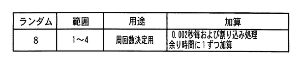
図16は、周回数nを決定するための乱数(ランダム8)を示す説明図である。ランダム8を生成するカウンタも、図5に示されたメイン処理におけるランダム1初期値決定用カウンタ更新処理(ステップS16,S19)と同様の処理で更新される。つまり、メイン処理において、少なくとも1回更新されるとともに、無限ループで更新され続ける。なお、この例では、ランダム8のとりうる範囲を1〜4としているが範囲は任意である。 FIG. 16 is an explanatory diagram showing a random number (random 8) for determining the number of turns n. The counter that generates random 8 is also updated by the same process as the random 1 initial value determination counter update process (steps S16 and S19) in the main process shown in FIG. That is, in the main process, it is updated at least once and is continuously updated in an infinite loop. In this example, the range that the random 8 can take is 1 to 4, but the range is arbitrary.
図17は、この実施の形態における判定用乱数更新処理(ステップS10)を示すフローチャートである。ステップS101〜S107およびステップS201〜S203の処理は、第1の実施の形態の場合と同じである。しかし、この実施の形態では、ランダム1が一周判定値と一致したときに(ステップS107)、周回数カウンタの値が+1される(ステップS125)。そして、周回数カウンタの値が周回数nと一致した場合に(ステップS126)、ステップS108以下の処理が実行される。周回数カウンタとは、大当り判定用カウンタのカウントの周回数を計数するカウンタである。なお、電源投入時には周回数nとして例えば「1」が設定される。また、周回数カウンタは電源投入時に0クリアされる。
FIG. 17 is a flowchart showing the determination random number update process (step S10) in this embodiment. The processes in steps S101 to S107 and steps S201 to S203 are the same as in the case of the first embodiment. However, in this embodiment, when the
すなわち、周回数カウンタの値が周回数nと一致した場合には、記憶値が新たな初期値として大当り判定用カウンタに設定され(ステップS108)、記憶値が一周判定値に設定されるとともに(ステップS109)、ランダム8を生成するためのカウンタの値が抽出される(ステップS121)。そして、抽出されたランダム8の値が周回数nに設定され(ステップS122)、周回数カウンタがクリアされる(ステップS123)。従って、大当り判定用カウンタがn回周回すると、ランダム8にもとづいて新たな周回数nが設定される。
That is, when the value of the lap number counter coincides with the lap number n, the stored value is set as a new initial value in the big hit determination counter (step S108), and the stored value is set as the one-round determination value ( In step S109, a counter value for generating random 8 is extracted (step S121). Then, the extracted random 8 value is set as the number of laps n (step S122), and the lap number counter is cleared (step S123). Therefore, when the big hit determination counter laps n times, a new lap number n is set based on the
図18は、図17に示された判定用乱数更新処理によって変化する大当り判定用カウンタの値の一例を示す説明図である。大当り判定用カウンタは、電源投入時に0クリアされるので、カウンタ値が「所定値s」まで進んだときにランダム1初期値決定用カウンタ(ランダム6を生成するためのカウンタ)の値が抽出され記憶される。すなわち、ランダム6の値が記憶される。なお、この例でも、所定値sの初期値(電源投入時の値)は150である。 FIG. 18 is an explanatory diagram showing an example of the value of the jackpot determination counter that is changed by the determination random number update process shown in FIG. Since the big hit determination counter is cleared to 0 when the power is turned on, the value of the random 1 initial value determination counter (counter for generating random 6) is extracted when the counter value advances to “predetermined value s”. Remembered. That is, a random value of 6 is stored. In this example as well, the initial value of the predetermined value s (the value when the power is turned on) is 150.
大当り判定用カウンタの値が「299」まで進み、そこで+1されて値が0に戻ると(ステップS101,S102,S103)、ステップS107の処理でカウンタ値が一周判定値と一致したことが検出され、かつ、周回数カウンタの値が周回数nに一致する(電源投入時の周回数n=1とする。)。すると、ステップS108の処理で、記憶値が大当り判定用カウンタに設定される。また、ステップS121およびS122の処理でランダム8が抽出され、新たな周回数nとして設定される。 When the value of the big hit determination counter advances to “299” and is incremented by 1 and the value returns to 0 (steps S101, S102, S103), it is detected that the counter value matches the round determination value in the process of step S107. In addition, the value of the lap number counter coincides with the lap number n (assuming the lap number n = 1 when the power is turned on). Then, in the process of step S108, the stored value is set in the big hit determination counter. In addition, random 8 is extracted in the processes of steps S121 and S122, and is set as a new number of times n.
その後、大当り判定用カウンタの値がn周すると、ステップS108の処理で、記憶値が大当り判定用カウンタに設定される。また、ステップS121およびS122の処理でランダム8が抽出され、新たな周回数nとして設定される。ここでは、記憶値は「195」であったとする。 Thereafter, when the value of the jackpot determination counter reaches n rounds, the stored value is set in the jackpot determination counter in the process of step S108. In addition, random 8 is extracted in the processes of steps S121 and S122, and is set as a new number of times n. Here, it is assumed that the stored value is “195”.
そして、大当り判定用カウンタの値が再度「所定値s」まで進むと、ランダム6(=P)が抽出され記憶される。その後、大当り判定用カウンタの値がn周すると、ステップS108の処理で、記憶値が大当り判定用カウンタに設定される。また、ステップS121およびS122の処理でランダム8が抽出され、新たな周回数nとして設定される。 Then, when the value of the big hit determination counter again advances to “predetermined value s”, random 6 (= P) is extracted and stored. Thereafter, when the value of the jackpot determination counter reaches n rounds, the stored value is set in the jackpot determination counter in the process of step S108. In addition, random 8 is extracted in the processes of steps S121 and S122, and is set as a new number of times n.
以上のように、この実施の形態では、大当り判定用カウンタの初期値が、カウンタ値が1周する毎に設定されるのではなく、カウンタ値がn周すると設定される。また、nの値は一定ではない。従って、大当り判定用カウンタの値が大当り判定値に一致するタイミングを外部で予測することはより難しくなる。 As described above, in this embodiment, the initial value of the big hit determination counter is not set every time the counter value makes one round, but is set when the counter value has n rounds. Also, the value of n is not constant. Therefore, it is more difficult to externally predict the timing at which the value of the jackpot determination counter matches the jackpot determination value.
なお、この実施の形態のような大当り判定用カウンタの値がn周すると初期値が更新される形態と、第2の実施の形態(実施の形態2)のようにランダム6を抽出するためのタイミングを決める所定値sを可変にする形態とを併用してもよい。 It should be noted that the initial value is updated when the value of the big hit determination counter is n times as in this embodiment, and the random 6 is extracted as in the second embodiment (embodiment 2). You may use together with the form which makes predetermined value s which determines a timing variable.
実施の形態4.
上記の各実施の形態では、大当り判定用カウンタの値が所定値sになったときに抽出されたランダム6の値が、そのまま大当り判定用カウンタの初期値として用いられた。しかし、抽出されたランダム6の値に対して何らかの演算を施し、演算結果を初期値として用いてもよい。
In each of the above-described embodiments, the random 6 value extracted when the value of the jackpot determination counter reaches the predetermined value s is used as the initial value of the jackpot determination counter as it is. However, some calculation may be performed on the extracted random 6 value, and the calculation result may be used as the initial value.
図19は、抽出されたランダム6に対して加算演算が施された結果を初期値として用いる場合の判定用乱数更新処理(ステップS10)を示すフローチャートである。ステップS101〜S107およびステップS201〜S203の処理は、第1の実施の形態の場合と同じである。 FIG. 19 is a flowchart showing the determination random number update process (step S10) in the case where the result obtained by performing the addition operation on the extracted random 6 is used as the initial value. The processes in steps S101 to S107 and steps S201 to S203 are the same as in the case of the first embodiment.
この実施の形態では、CPU56は、ステップS107において大当り判定用カウンタの値が一周判定値と一致した場合には、あらためてランダム6の値を抽出する(ステップS130)。そして、ここでの抽出値と記憶値とを加算する(ステップS131)。次いで、加算結果を、初期値として大当り判定用カウンタに設定する(ステップS132)。なお、加算値が300以上になったときには、300を引いた値が設定される。
In this embodiment, when the value of the big hit determination counter coincides with the round determination value in step S107, the CPU 56 extracts a
図20は、図19に示された判定用乱数更新処理によって変化する大当り判定用カウンタの値の一例を示す説明図である。大当り判定用カウンタは、電源投入時に0クリアされるので、カウンタ値が「所定値s」まで進んだときにランダム1初期値決定用カウンタ(ランダム6を生成するためのカウンタ)の値が抽出され記憶される。すなわち、ランダム6の値が記憶される。なお、この例でも所定値sは150である。 FIG. 20 is an explanatory diagram illustrating an example of the value of the jackpot determination counter that is changed by the determination random number update process illustrated in FIG. Since the big hit determination counter is cleared to 0 when the power is turned on, the value of the random 1 initial value determination counter (counter for generating random 6) is extracted when the counter value advances to “predetermined value s”. Remembered. That is, a random value of 6 is stored. In this example, the predetermined value s is 150.
大当り判定用カウンタの値が「299」まで進み、そこで+1されて値が0に戻ると、カウンタ値が一周判定値と一致したことが検出される。すると、ステップS130の処理でランダム6の値が抽出される。ここでは、抽出値は「125」であったとする。また、記憶値は「19」であったとする。従って、記憶値と抽出値との加算値「144」が大当り判定用カウンタに設定される。従って、この時点から、大当り判定用カウンタは、初期値「144」から歩進することになる。 When the value of the big hit determination counter advances to “299” and is incremented by 1 to return to 0, it is detected that the counter value matches the round determination value. Then, a random value of 6 is extracted in the process of step S130. Here, it is assumed that the extracted value is “125”. The stored value is “19”. Therefore, the added value “144” of the stored value and the extracted value is set in the jackpot determination counter. Therefore, from this point, the big hit determination counter advances from the initial value “144”.
大当り判定用カウンタの値が再び「所定値s」まで進むと、ランダム6が抽出され記憶される。ここでは、抽出値は「195」であったとする。大当り判定用カウンタの値が「144」になると、カウンタ値が一周判定値と一致したことが検出される。すると、ステップS130の処理でランダム6の値が抽出される。ここでは、抽出値は「186」であったとする。また、記憶値は「195」である。従って、記憶値と抽出値との加算値は「381」であるが、ランダム1のとりうる範囲は0〜299であるから、「300」を減算した「81」が大当り判定用カウンタに設定される。従って、この時点から、大当り判定用カウンタは、初期値「81」から歩進することになる。 When the value of the big hit determination counter again reaches “predetermined value s”, random 6 is extracted and stored. Here, it is assumed that the extracted value is “195”. When the value of the big hit determination counter becomes “144”, it is detected that the counter value matches the round determination value. Then, a random value of 6 is extracted in the process of step S130. Here, it is assumed that the extracted value is “186”. The stored value is “195”. Therefore, although the added value of the stored value and the extracted value is “381”, the range that can be taken by random 1 is 0 to 299. Therefore, “81” obtained by subtracting “300” is set as the jackpot determination counter. The Therefore, from this point, the big hit determination counter advances from the initial value “81”.
そして、大当り判定用カウンタの値が再び「所定値s」まで進むと、ランダム6(=P)が抽出され記憶される。そして、大当り判定用カウンタの値が「81」になるとカウンタ値が一周判定値と一致するので、記憶値と抽出値の加算が行われ加算結果「P」が大当り判定用カウンタに新たな初期値として設定される。従って、この時点から、大当り判定用カウンタは、初期値「P」から歩進する。 Then, when the value of the jackpot determination counter again advances to “predetermined value s”, random 6 (= P) is extracted and stored. When the value of the jackpot determination counter reaches “81”, the counter value coincides with the one-round determination value. Therefore, the stored value and the extracted value are added, and the addition result “P” becomes a new initial value in the jackpot determination counter. Set as Therefore, from this point, the big hit determination counter advances from the initial value “P”.
以上のように、この実施の形態では、複数のタイミングにおいて抽出されたランダム6の各値に対して加算処理を施して大当り判定用カウンタの初期値とするので、初期値は複雑な過程を経て決定されたものとなる。従って、やはり、大当り判定用カウンタの値が大当り判定値に一致するタイミングを外部で予測することはさらに難しくなる。 As described above, in this embodiment, since each random 6 value extracted at a plurality of timings is subjected to addition processing to obtain the initial value of the jackpot determination counter, the initial value undergoes a complicated process. It will be decided. Accordingly, it is still more difficult to predict the timing at which the value of the jackpot determination counter coincides with the jackpot determination value.
なお、この実施の形態では、演算処理として加算処理が用いられたが、演算は加算に限られない。減算や乗算であってもよいし、その他任意の演算を用いることができる。また、第3の実施の形態のような大当り判定用カウンタの値がn周すると初期値が更新される形態や、第2の実施の形態のようにランダム6を抽出するためのタイミングを決める所定値sを可変にする形態を併用してもよい。 In this embodiment, addition processing is used as calculation processing, but the calculation is not limited to addition. Subtraction or multiplication may be used, and any other calculation can be used. In addition, the initial value is updated when the value of the jackpot determination counter is n times as in the third embodiment, or the predetermined timing for determining the random 6 is extracted as in the second embodiment. A form in which the value s is variable may be used in combination.
実施の形態5.
上記の各実施の形態では、大当り判定用カウンタの値が1周する間にランダム6の値が抽出されたが、カウントが所定周するとランダム6の値を抽出するようにしてもよい。さらに、初期値を設定するためのカウントの周回数を可変にしてもよい。図21は、そのような第5の実施の形態における判定用乱数更新処理(ステップS10)を示すフローチャートである。この例では、大当り判定用カウンタがn周するとランダム6の値が抽出され、大当り判定用カウンタがm周すると大当り判定用カウンタに初期値が設定される。
In each of the above-described embodiments, the random 6 value is extracted while the value of the big hit determination counter makes one round. However, the random 6 value may be extracted when the count makes a predetermined round. Further, the number of counts for setting the initial value may be variable. FIG. 21 is a flowchart showing the determination random number update process (step S10) in the fifth embodiment. In this example, a random 6 value is extracted when the big hit determination counter makes n turns, and an initial value is set in the big hit determination counter when the big hit determination counter makes m turns.
ステップS101〜S109およびステップS201〜S203の処理は、第1の実施の形態の場合と同じであるが、この実施の形態では、大当り判定用カウンタの値が所定値sになっているかどうかの判定(ステップS104)は、周回数カウンタの値がnの倍数になっているときにのみ実行される(ステップS140)。 The processing in steps S101 to S109 and steps S201 to S203 is the same as in the first embodiment, but in this embodiment, it is determined whether or not the value of the jackpot determination counter is a predetermined value s. (Step S104) is executed only when the value of the circulation counter is a multiple of n (Step S140).
よって、ステップS107において大当り判定用カウンタの値が1周したことが検出されると、周回数カウンタの値は+1される(ステップS141)。また、周回数カウンタの値がmになっているときにのみステップS108およびS109の初期値更新処理が実行される(ステップS142)。 Accordingly, when it is detected in step S107 that the value of the big hit determination counter has made one round, the value of the number of rounds counter is incremented by one (step S141). Only when the value of the circulation counter is m, the initial value update process of steps S108 and S109 is executed (step S142).
図22は、図21に示された判定用乱数更新処理によって変化する大当り判定用カウンタの値の一例を示す説明図である。図21に示すように、大当り判定用カウンタのカウントがn周目に入ると、ステップS140の判断が「Yes」となって、カウンタ値が「所定値s」まで進んだときにランダム6の値が抽出され記憶される。なお、この例では、所定値sは150であるが、その値を任意に設定することができる。 FIG. 22 is an explanatory diagram illustrating an example of the value of the jackpot determination counter that is changed by the determination random number update process illustrated in FIG. As shown in FIG. 21, when the count of the big hit determination counter enters the nth lap, the determination in step S140 becomes “Yes”, and a random 6 value is obtained when the counter value advances to “predetermined value s”. Is extracted and stored. In this example, the predetermined value s is 150, but the value can be arbitrarily set.
そして、大当り判定用カウンタのカウントのm周目に大当り判定用カウンタの値が「299」まで進んで+1されて値が0に戻ると、ステップS107およびS142の判断が「Yes」とる。すると、ステップS108の処理で、記憶値が大当り判定用カウンタに設定される。記憶値は同時に一周判定値にも設定される(ステップS109)。なお、図22に示された例では、この時点の記憶値は「195」である。従って、この時点から、大当り判定用カウンタは、初期値「195」から歩進することになる。 Then, when the value of the big hit determination counter advances to “299” and is incremented by 1 on the mth round of the count of the big hit determination counter, the determination in steps S107 and S142 is “Yes”. Then, in the process of step S108, the stored value is set in the big hit determination counter. At the same time, the stored value is also set as the one-round determination value (step S109). In the example shown in FIG. 22, the stored value at this time is “195”. Therefore, from this time, the big hit determination counter advances from the initial value “195”.
大当り判定用カウンタが再びn周進んで「所定値s」になると、ランダム6が抽出され記憶される。ここでは、抽出値は「P」であったとする。そして、大当り判定用カウンタのカウントのm周目に大当り判定用カウンタの値が「195」になると、記憶されているランダム6の値「P」が大当り判定用カウンタに新たな初期値として設定される。従って、この時点から、大当り判定用カウンタは、初期値「P」から歩進する。 When the big hit determination counter again advances n rounds to “predetermined value s”, random 6 is extracted and stored. Here, it is assumed that the extracted value is “P”. When the value of the big hit determination counter reaches “195” on the m-th round of the count of the big hit determination counter, the stored random value “P” is set as a new initial value in the big hit determination counter. The Therefore, from this point, the big hit determination counter advances from the initial value “P”.
以上のように、この実施の形態では、大当り判定用カウンタの初期値となるランダム6の抽出および初期値の設定は、大当り判定用カウンタのカウントが所定周すると実行される。また、ランダム6の抽出に関する所定周と初期値の設定に関する所定周とは異なっていることが好ましい。このように、飛び飛びのタイミングで、ランダム6の抽出および初期値の設定を行うようにしても、大当り判定用カウンタの初期値はランダムに変化するので、外部において、大当り判定用カウンタの値が大当り判定値と一致するタイミングを予測することが困難になる。そして、この実施の形態では、上記の各実施の形態の場合に比べて、ランダム6の抽出タイミングと初期値の設定タイミングとを時間的に離れたタイミングとすることができる。 As described above, in this embodiment, the extraction of the random 6 that is the initial value of the jackpot determination counter and the setting of the initial value are executed when the count of the jackpot determination counter is a predetermined number of times. Further, it is preferable that the predetermined circumference relating to the random 6 extraction and the predetermined circumference relating to the setting of the initial value are different. In this way, even if random 6 is extracted and the initial value is set at the jumping timing, the initial value of the big hit determination counter changes randomly, so that the value of the big hit determination counter is externally changed It becomes difficult to predict the timing that coincides with the determination value. In this embodiment, the extraction timing of the random 6 and the setting timing of the initial value can be set apart from each other as compared with the case of each of the above embodiments.
なお、この実施の形態では、n,mを固定値としたが、それらを可変値としてもよい。例えば、それぞれに対応した乱数を抽出し抽出された乱数値に応じて変更するようにしてもよい。その場合には、ランダム6の抽出および初期値設定のタイミングがさらにばらつくので、大当り判定用カウンタの値が大当り判定値と一致するタイミングを予測することはより困難になる。 In this embodiment, n and m are fixed values, but they may be variable values. For example, a random number corresponding to each may be extracted and changed according to the extracted random value. In that case, since the timing of random 6 extraction and initial value setting further varies, it is more difficult to predict the timing at which the value of the jackpot determination counter matches the jackpot determination value.
実施の形態6.
図19および図20に示された第4の実施の形態(実施の形態4)では、1つのランダム6の記憶値と大当り判定用カウンタが1周したときのランダム6の抽出値とに所定の演算処理を施し演算結果を大当り判定用カウンタの初期値としたが、複数の記憶値を用いてもよい。
In the fourth embodiment (Embodiment 4) shown in FIG. 19 and FIG. 20, a predetermined value is stored in one random 6 stored value and a random 6 extracted value when the big hit determination counter makes one round. Although the calculation process is performed and the calculation result is set as the initial value of the jackpot determination counter, a plurality of stored values may be used.
図23は、2つの記憶値を用いた場合の大当り判定用カウンタの値の変化例を示す説明図である。この例では、ランダム6を抽出するタイミングを決めるための2つの所定値s1,s2が用いられ、それぞれあらかじめ定められた「150」,「250」とされる。大当り判定用カウンタは、電源投入時に0クリアされるので、カウンタ値が「所定値s1」まで進んだときにランダム1初期値決定用カウンタ(ランダム6を生成するためのカウンタ)の値が抽出され記憶される。さらに、カウンタ値が「所定値s2」まで進んだときにランダム1初期値決定用カウンタの値が抽出され記憶される。 FIG. 23 is an explanatory diagram showing an example of a change in the value of the jackpot determination counter when two stored values are used. In this example, two predetermined values s1 and s2 for determining the timing for extracting the random 6 are used, which are set to “150” and “250” respectively determined in advance. Since the big hit determination counter is cleared to 0 when the power is turned on, the value of the random 1 initial value determination counter (counter for generating random 6) is extracted when the counter value advances to “predetermined value s1”. Remembered. Further, when the counter value advances to “predetermined value s2”, the value of the random 1 initial value determination counter is extracted and stored.
大当り判定用カウンタの値が「299」まで進み、そこで+1されて値が0に戻ると、カウンタ値が一周判定値と一致したことが検出される。ここで、ランダム6の値が再び抽出される。ここでは、抽出値は「125」であったとする。また、記憶値は「19」および「151」であったとする。従って、記憶値と抽出値との加算値「295」が大当り判定用カウンタに設定される。従って、この時点から、大当り判定用カウンタは、初期値「295」から歩進することになる。 When the value of the big hit determination counter advances to “299” and is incremented by 1 to return to 0, it is detected that the counter value matches the round determination value. Here, the value of random 6 is extracted again. Here, it is assumed that the extracted value is “125”. The stored values are “19” and “151”. Therefore, the addition value “295” of the stored value and the extracted value is set in the jackpot determination counter. Therefore, from this point, the big hit determination counter advances from the initial value “295”.
大当り判定用カウンタの値が再び「所定値s1」まで進むと、ランダム6が抽出され記憶される。ここでは、記憶される値は「195」であったとする。さらに、カウンタ値が「所定値s2」まで進んだときにランダム1初期値決定用カウンタの値が抽出され記憶される。記憶される値は「145」であったとする。大当り判定用カウンタの値が「295」になると、カウンタ値が一周判定値と一致したことが検出される。すると、ランダム6の値が抽出される。ここでは、抽出値は「186」であったとする。また、記憶値は「195」および「145」である。従って、記憶値と抽出値との加算値は「526」であるが、ランダム1のとりうる範囲は0〜299であるから、「300」を減算した「226」が大当り判定用カウンタに設定される。従って、この時点から、大当り判定用カウンタは、初期値「226」から歩進することになる。 When the value of the big hit determination counter again proceeds to “predetermined value s1”, random 6 is extracted and stored. Here, it is assumed that the stored value is “195”. Further, when the counter value advances to “predetermined value s2”, the value of the random 1 initial value determination counter is extracted and stored. Assume that the stored value is “145”. When the value of the big hit determination counter reaches “295”, it is detected that the counter value matches the round determination value. Then, a random value of 6 is extracted. Here, it is assumed that the extracted value is “186”. The stored values are “195” and “145”. Therefore, the sum of the stored value and the extracted value is “526”, but the range that can be taken by random 1 is 0 to 299. Therefore, “226” obtained by subtracting “300” is set in the jackpot determination counter. The Therefore, from this point, the big hit determination counter advances from the initial value “226”.
そして、大当り判定用カウンタの値が再び「所定値s1」および「所定値s2」まで進むと、ランダム6(=P2,P1)が抽出され記憶される。そして、大当り判定用カウンタの値が「226」になるとカウンタ値が一周判定値と一致するので、記憶値と抽出値の加算が行われ加算結果「R」が大当り判定用カウンタに新たな初期値として設定される。従って、この時点から、大当り判定用カウンタは、初期値「R」から歩進する。 When the value of the big hit determination counter again advances to “predetermined value s1” and “predetermined value s2”, random 6 (= P2, P1) is extracted and stored. When the value of the jackpot determination counter reaches “226”, the counter value matches the round determination value. Therefore, the stored value and the extracted value are added, and the addition result “R” becomes a new initial value in the jackpot determination counter. Set as Therefore, from this point of time, the jackpot determination counter advances from the initial value “R”.
以上のように、この実施の形態では、3つのタイミングにおいて抽出されたランダム6の各値に対して加算処理を施して大当り判定用カウンタの初期値とするので、初期値は複雑な過程を経て決定されたものとなる。従って、大当り判定用カウンタの値が大当り判定値に一致するタイミングを外部で予測することはさらに難しくなる。 As described above, in this embodiment, the random value extracted at three timings is added to obtain the initial value of the jackpot determination counter, so that the initial value undergoes a complicated process. It will be decided. Therefore, it becomes more difficult to predict the timing at which the value of the jackpot determination counter matches the jackpot determination value.
なお、この実施の形態でも、演算処理として加算処理が用いられたが、演算は加算に限られない。減算や乗算であってもよいし、その他任意の演算を用いることができる。また、第3の実施の形態のような大当り判定用カウンタの値がn周すると初期値が更新される形態を併用してもよい。 In this embodiment, addition processing is used as calculation processing, but the calculation is not limited to addition. Subtraction or multiplication may be used, and any other calculation can be used. Further, a configuration in which the initial value is updated when the value of the jackpot determination counter n times as in the third embodiment may be used together.
実施の形態7.
上記の実施の形態では、ランダム6を抽出するためのタイミングを決める所定値s1,s2をあらかじめ定められた固定値としたが、所定値s1,s2を可変にしてもよい。図24は、大当り判定用カウンタのカウントのn周目では、所定値s1,s2を「20」,「200」にする場合の大当り判定用カウンタの値の変化例を示す説明図である。
In the above-described embodiment, the predetermined values s1 and s2 for determining the timing for extracting the random 6 are fixed values set in advance, but the predetermined values s1 and s2 may be variable. FIG. 24 is an explanatory diagram showing an example of a change in the value of the big hit determination counter when the predetermined values s1 and s2 are set to “20” and “200” in the nth round of the count of the big hit determination counter.
図24に示すように、大当り判定用カウンタのカウントの1周目〜(n−1)周目までは第6の実施の形態(実施の形態6)と同様の処理が行われる。第n周目では、大当り判定用カウンタの値が「所定値s1=20」および「所定値s2=200」まで進むとランダム6(=P1,P2)が抽出され記憶される。そして、n周目のカウントが「S」から始まったとすると、大当り判定用カウンタの値が再び「S」になったときに、ランダム6の値が抽出され、抽出値と記憶値P1,P2とを対象とした演算が行われ、演算結果Tが大当り判定用カウンタに初期値Tとして設定される。 As shown in FIG. 24, the same processing as in the sixth embodiment (sixth embodiment) is performed from the first round to the (n-1) th round of the count of the big hit determination counter. In the n-th round, when the value of the big hit determination counter advances to “predetermined value s1 = 20” and “predetermined value s2 = 200”, random 6 (= P1, P2) is extracted and stored. If the count of the n-th cycle starts from “S”, when the value of the jackpot determination counter becomes “S” again, a random value of 6 is extracted, and the extracted value and the stored values P1, P2 and The calculation result T is set as the initial value T in the jackpot determination counter.
この場合には、3つのタイミングにおいて抽出されたランダム6の各値に対して演算処理を施して大当り判定用カウンタの初期値とする形態において、大当り判定用カウンタのカウントの特定の周回ではランダム6の抽出タイミングを異ならせているので、初期値はより複雑な演算過程を経ることになり、大当り判定用カウンタの初期値がよりランダムになる。
In this case, in the form in which arithmetic processing is performed on each value of random 6 extracted at three timings to obtain the initial value of the jackpot determination counter, the
なお、この実施の形態ではnを固定的な値としたが、nを例えば乱数に応じた可変値としてもよい。また、大当り判定用カウンタのカウントの特定の周回ではランダム6の抽出回数を変えるようにしてもよい。すなわち、記憶値の個数を変えるようにしてもよい。 In this embodiment, n is a fixed value, but n may be a variable value corresponding to a random number, for example. Further, the number of random 6 extractions may be changed in a specific round of the count of the big hit determination counter. That is, the number of stored values may be changed.
以上のように、上記の各実施の形態では、大当り判定用カウンタのカウント値が所定値になるとランダム6を抽出して記憶し、大当り判定用カウンタのカウントが所定回周回すると記憶されていたランダム6の値を初期値として大当り判定用カウンタに設定する。よって、例えば図12に示されたように、新たな初期値として用いられるランダム6の抽出タイミングは一定ではない。すると、ランダム1を生成するためのカウンタすなわち大当り判定用カウンタの初期値のランダム性が増し、その結果、大当り判定用カウンタ値が大当り判定値になるタイミングがよりランダムになって外部から予測しづらいものとなる。
As described above, in each of the above embodiments, the
なお、上記の各実施の形態の遊技機、すなわち図1の正面図に示されたパチンコ遊技機は、始動入賞にもとづいて可変表示部9に可変表示される特別図柄の停止図柄が所定の図柄の組み合わせになると所定の遊技価値が遊技者に付与可能になる第1種パチンコ遊技機であったが、始動入賞にもとづいて開放する電動役物の所定領域への入賞があると所定の遊技価値が遊技者に付与可能になる第2種パチンコ遊技機や、始動入賞にもとづいて可変表示される図柄の停止図柄が所定の図柄の組み合わせになると開放する所定の電動役物への入賞があると所定の権利が発生または継続する第3種パチンコ遊技機であっても、本発明を適用できる。
Note that in the gaming machines of the above-described embodiments, that is, the pachinko gaming machine shown in the front view of FIG. 1, a special symbol that is variably displayed on the
また、可変表示部9の実現手段はいかなるものでもよく、例えば、CRTやLED等の表示器によって実現することができるし、ドラム式やベルト式の可変表示装置を用いてもよい。
Further, any means for realizing the
また、上記の各実施の形態では、図5に示されたメイン処理はCPU56の外部から与えられる定期リセット信号によって起動されたが、定期リセット信号を用いず、例えばCPU56の内部のタイマ割込等によってメイン処理が実行される場合にも本発明を適用可能である。 Further, in each of the above embodiments, the main process shown in FIG. 5 is started by a periodic reset signal given from the outside of the CPU 56, but without using the periodic reset signal, for example, an internal timer interrupt of the CPU 56, etc. The present invention can also be applied to the case where the main process is executed.
なお、遊技機は、特定遊技判定用カウンタに初期値が設定される条件となる所定周回を決定するための初期設定タイミング決定手段をさらに備えていてもよい。特定遊技判定用カウンタに初期値が設定される条件となる所定周回を決定するための初期設定タイミング決定手段が設けられている場合には、初期値設定タイミングが時間的によりばらつくことによって、特定遊技判定用の数値が判定値と一致するタイミングを外部で推測することがさらに困難になる効果がある。 Note that the gaming machine may further include an initial setting timing determining means for determining a predetermined number of times as a condition for setting an initial value in the specific game determination counter. In a case where an initial setting timing determining means for determining a predetermined number of rounds that is a condition for setting an initial value in the specific game determination counter is provided, the initial value setting timing varies more in time, so that the specific game There is an effect that it is more difficult to externally estimate the timing at which the numerical value for determination matches the determination value.
また、初期設定タイミング決定手段は、所定周回を決定するための数値を無限ループで更新するように構成されていてもよい。所定周回を決定するための数値が無限ループで更新されるように構成されている場合には、初期値設定タイミングのばらつきがより大きくなって、特定遊技判定用の数値が判定値と一致するタイミングを外部で推測することが一層困難になる効果がある。 Further, the initial setting timing determining means may be configured to update a numerical value for determining a predetermined number of rounds in an infinite loop. When the numerical value for determining the predetermined number of laps is configured to be updated in an infinite loop, the variation in the initial value setting timing becomes larger and the specific game determination numerical value matches the determination value This has the effect of making it more difficult to guess outside.
31 主基板
53 基本回路
54 ROM
55 RAM
56 CPU
57 I/Oポート
66 定期リセット回路
31
55 RAM
56 CPU
57 I / O port 66 Periodic reset circuit
Claims (1)
所定の数値範囲内で特定遊技判定用カウンタの値を更新する特定遊技判定用カウンタ更新手段と、
所定の条件が成立すると前記特定遊技判定用カウンタの値を抽出し、抽出値と判定値とを比較してそれらが一致すると特定遊技状態に移行させる遊技制御手段と、
前記特定遊技判定用カウンタの更新初期値を決定するための初期値決定用カウンタの値を更新する初期値決定用カウンタ更新手段と、
前記特定遊技判定用カウンタの値が所定値になったことを条件に前記初期値決定用カウンタの値を抽出して前記特定遊技判定用カウンタが所定周回するまで記憶しておくとともに、該記憶した前記初期値決定用カウンタの値にもとづいて前記特定遊技判定用カウンタが所定周回したときに前記特定遊技判定用カウンタに初期値を設定する初期値更新手段と、
前記初期値決定用カウンタの値が抽出されるタイミングとなる前記所定値を決定するための数値決定手段とを備え、
前記初期値更新手段は、前記記憶した前記初期値決定用カウンタの値を用いて演算処理を行い演算結果を初期値として前記特定遊技判定用カウンタに設定し、
前記数値決定手段は、
前記初期値決定用カウンタとは別のカウンタを前記初期値決定用カウンタとは別の更新条件で更新する手段であって、前記特定遊技判定用カウンタと同じ数値範囲内で所定値決定用カウンタの値を更新する所定値決定用カウンタ更新手段と、
前記特定遊技判定用カウンタが前記所定周回したときに前記所定値決定用カウンタの値を抽出し、該抽出した値を前記所定値として記憶する抽出記憶手段とを備えた
ことを特徴とする遊技機。 A gaming machine that performs a game based on a player's operation and can shift to a specific gaming state that is advantageous to the player,
Specific game determination counter update means for updating the value of the specific game determination counter within a predetermined numerical range;
A game control means for extracting the value of the specific game determination counter when a predetermined condition is satisfied, comparing the extracted value with the determination value, and shifting to a specific game state when they match;
Initial value determination counter updating means for updating an initial value determination counter value for determining an update initial value of the specific game determination counter;
On the condition that the value of the specific game determination counter reaches a predetermined value, the value of the initial value determination counter is extracted and stored until the specific game determination counter makes a predetermined number of laps . An initial value updating means for setting an initial value in the specific game determination counter when the specific game determination counter circulates based on a value of the initial value determination counter ;
Numerical value determining means for determining the predetermined value that is a timing at which the value of the initial value determining counter is extracted ;
The initial value update means performs an arithmetic process using the stored value of the initial value determination counter, sets an arithmetic result as an initial value in the specific game determination counter ,
The numerical value determining means includes
A means for updating a counter different from the initial value determination counter under an update condition different from that of the initial value determination counter, wherein the predetermined value determination counter A predetermined value determining counter updating means for updating the value;
A gaming machine comprising: an extraction storage means for extracting the value of the predetermined value determination counter when the specific game determination counter makes the predetermined number of laps and storing the extracted value as the predetermined value .
Priority Applications (1)
| Application Number | Priority Date | Filing Date | Title |
|---|---|---|---|
| JP2007202920A JP4620089B2 (en) | 2007-08-03 | 2007-08-03 | Game machine |
Applications Claiming Priority (1)
| Application Number | Priority Date | Filing Date | Title |
|---|---|---|---|
| JP2007202920A JP4620089B2 (en) | 2007-08-03 | 2007-08-03 | Game machine |
Related Parent Applications (1)
| Application Number | Title | Priority Date | Filing Date |
|---|---|---|---|
| JP11036558A Division JP2000233059A (en) | 1999-02-15 | 1999-02-15 | Game machine |
Related Child Applications (1)
| Application Number | Title | Priority Date | Filing Date |
|---|---|---|---|
| JP2007259821A Division JP2008012365A (en) | 2007-10-03 | 2007-10-03 | Game machine |
Publications (3)
| Publication Number | Publication Date |
|---|---|
| JP2007283129A JP2007283129A (en) | 2007-11-01 |
| JP2007283129A5 JP2007283129A5 (en) | 2008-09-18 |
| JP4620089B2 true JP4620089B2 (en) | 2011-01-26 |
Family
ID=38755395
Family Applications (1)
| Application Number | Title | Priority Date | Filing Date |
|---|---|---|---|
| JP2007202920A Expired - Fee Related JP4620089B2 (en) | 2007-08-03 | 2007-08-03 | Game machine |
Country Status (1)
| Country | Link |
|---|---|
| JP (1) | JP4620089B2 (en) |
-
2007
- 2007-08-03 JP JP2007202920A patent/JP4620089B2/en not_active Expired - Fee Related
Also Published As
| Publication number | Publication date |
|---|---|
| JP2007283129A (en) | 2007-11-01 |
Similar Documents
| Publication | Publication Date | Title |
|---|---|---|
| JP3836265B2 (en) | Game machine | |
| JP4180161B2 (en) | Game machine | |
| JP2000061087A (en) | Game machine | |
| JP4641019B2 (en) | Game machine | |
| JPH11216237A (en) | Game machine | |
| JP4271283B2 (en) | Game machine | |
| JP4620089B2 (en) | Game machine | |
| JP4620088B2 (en) | Game machine | |
| JP4620092B2 (en) | Game machine | |
| JP4620087B2 (en) | Game machine | |
| JP4620091B2 (en) | Game machine | |
| JP4620090B2 (en) | Game machine | |
| JP4255540B2 (en) | Game machine | |
| JP2000233059A (en) | Game machine | |
| JP4503257B2 (en) | Game machine | |
| JP2008012363A (en) | Game machine | |
| JP2008012366A (en) | Game machine | |
| JP2008012365A (en) | Game machine | |
| JP2008012368A (en) | Game machine | |
| JP2008012367A (en) | Game machine | |
| JP2008012364A (en) | Game machine | |
| JP4689700B2 (en) | Game machine | |
| JP2980246B1 (en) | Gaming machine | |
| JP4558820B2 (en) | Game machine | |
| JP4459949B2 (en) | Game machine |
Legal Events
| Date | Code | Title | Description |
|---|---|---|---|
| A621 | Written request for application examination |
Free format text: JAPANESE INTERMEDIATE CODE: A621 Effective date: 20070803 |
|
| A521 | Written amendment |
Free format text: JAPANESE INTERMEDIATE CODE: A523 Effective date: 20080804 |
|
| A871 | Explanation of circumstances concerning accelerated examination |
Free format text: JAPANESE INTERMEDIATE CODE: A871 Effective date: 20080804 |
|
| A975 | Report on accelerated examination |
Free format text: JAPANESE INTERMEDIATE CODE: A971005 Effective date: 20080822 |
|
| A131 | Notification of reasons for refusal |
Free format text: JAPANESE INTERMEDIATE CODE: A131 Effective date: 20080826 |
|
| A02 | Decision of refusal |
Free format text: JAPANESE INTERMEDIATE CODE: A02 Effective date: 20081224 |
|
| A521 | Written amendment |
Free format text: JAPANESE INTERMEDIATE CODE: A523 Effective date: 20100917 |
|
| A01 | Written decision to grant a patent or to grant a registration (utility model) |
Free format text: JAPANESE INTERMEDIATE CODE: A01 |
|
| A61 | First payment of annual fees (during grant procedure) |
Free format text: JAPANESE INTERMEDIATE CODE: A61 Effective date: 20101027 |
|
| FPAY | Renewal fee payment (event date is renewal date of database) |
Free format text: PAYMENT UNTIL: 20131105 Year of fee payment: 3 |
|
| R150 | Certificate of patent or registration of utility model |
Free format text: JAPANESE INTERMEDIATE CODE: R150 |
|
| FPAY | Renewal fee payment (event date is renewal date of database) |
Free format text: PAYMENT UNTIL: 20131105 Year of fee payment: 3 |
|
| R250 | Receipt of annual fees |
Free format text: JAPANESE INTERMEDIATE CODE: R250 |
|
| R250 | Receipt of annual fees |
Free format text: JAPANESE INTERMEDIATE CODE: R250 |
|
| R250 | Receipt of annual fees |
Free format text: JAPANESE INTERMEDIATE CODE: R250 |
|
| R250 | Receipt of annual fees |
Free format text: JAPANESE INTERMEDIATE CODE: R250 |
|
| R250 | Receipt of annual fees |
Free format text: JAPANESE INTERMEDIATE CODE: R250 |
|
| LAPS | Cancellation because of no payment of annual fees |