JP4620071B2 - Contact materials for vacuum circuit breakers - Google Patents
Contact materials for vacuum circuit breakers Download PDFInfo
- Publication number
- JP4620071B2 JP4620071B2 JP2007068013A JP2007068013A JP4620071B2 JP 4620071 B2 JP4620071 B2 JP 4620071B2 JP 2007068013 A JP2007068013 A JP 2007068013A JP 2007068013 A JP2007068013 A JP 2007068013A JP 4620071 B2 JP4620071 B2 JP 4620071B2
- Authority
- JP
- Japan
- Prior art keywords
- alloy powder
- vacuum circuit
- circuit breaker
- contact
- contact material
- Prior art date
- Legal status (The legal status is an assumption and is not a legal conclusion. Google has not performed a legal analysis and makes no representation as to the accuracy of the status listed.)
- Expired - Fee Related
Links
Images

Description
本発明はCu−Cr合金粉末およびそれを用いた真空遮断器用接点材料に係り、特に、固相法による製造工程において粉末成形性を向上させることが可能なCu−Cr合金粉末およびそれを用いた真空遮断器用接点材料に関する。 The present invention relates to a Cu-Cr alloy powder and a contact material for a vacuum circuit breaker using the same, and in particular, a Cu-Cr alloy powder capable of improving powder formability in a production process by a solid phase method and the same. The present invention relates to a contact material for a vacuum circuit breaker.
遮断器は平常状態の電路を開閉したり、接地事故や短絡事故などの異常時に,故障状態を検知する過電流継電器などと組み合わされて、自動的に瞬時に電路を遮断したりするために、電力設備,変電所内機器,高速鉄道車輌等に広く使用されている。特に真空遮断器は、10−4Pa程度の高真空に維持した容器(真空バルブ)内に対向配置した1対の接点部材(接触子)を開閉することにより、電路の開閉を行うものである。 The circuit breaker is used in combination with an overcurrent relay that detects a failure state in the event of an abnormality such as a grounding accident or a short-circuit accident, and automatically shuts off the electric circuit instantaneously. Widely used in power equipment, substation equipment, high-speed railway vehicles, etc. In particular, the vacuum circuit breaker opens and closes the electric circuit by opening and closing a pair of contact members (contacts) arranged oppositely in a container (vacuum valve) maintained at a high vacuum of about 10 −4 Pa. .
図1は一般的な真空遮断器の構造例を示す断面図である。図1において接点の開閉動作が行われる遮断室1は、絶縁材料から成り略円筒状に形成された絶縁容器2と,この絶縁容器2の上下端に封止金属3a,3bを介して設けた金属製の蓋体4a,4bとによって区画形成され真空気密に構成されている。遮断室1内には軸方向に対向するように1対の導電棒5,6が配置され、その各導電棒5,6の対向する端部に、一対の電極7,8が取付けられている。図においては上部側の電極7を固定電極とする一方、下部側の電極8を可動電極としている。また可動電極8の導電棒6には、伸縮自在のベローズ9が装着されており、遮断室1内を真空気密に保持した状態で、可動電極8の軸方向における往復動を可能にしている。このベローズ9の上部には金属製のアークシールド10が設けられており、このアークシールド10によってベローズ9がアーク蒸気によって覆われることを防止している。
FIG. 1 is a sectional view showing an example of the structure of a general vacuum circuit breaker. In FIG. 1, a shut-off chamber 1 in which contacts are opened and closed is provided with an
また遮断室1内には、対向する一対の電極7,8を覆うように金属製のアークシールド11が配設されており、このアークシールド11によって絶縁容器2がアーク蒸気によって覆われることが防止される。
Further, a metal arc shield 11 is disposed in the shut-off chamber 1 so as to cover a pair of
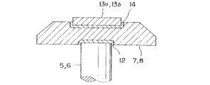
また図2に拡大して示すように、電極8は導電棒6の端部に形成されるろう付け部12に加熱接合により固定されるか、または、かしめ加工によって圧着接続される。接点部材13aは電極8の端面中央部にろう材14を介して一体に固着されている。なお、図2に示す固定側接点部材13bも同様に、固定電極7の端面にろう材を介して一体に接合されている。
Further, as shown in FIG. 2 in an enlarged manner, the electrode 8 is fixed to the brazed portion 12 formed at the end of the
上記構成の真空遮断器によれば、高真空中における高い絶縁耐力を利用できるため、対向する接点部材の開閉ストロークを短くできる特徴を有している。 According to the vacuum circuit breaker of the said structure, since the high dielectric strength in a high vacuum can be utilized, it has the characteristic which can shorten the opening / closing stroke of the contact member which opposes.
一般的に接点材料として要求される特性は、接点が高頻度にわたって開閉することから、(1)遮断容量が大きいこと、(2)耐電圧が高いこと、(3)接触抵抗が小さいこと、(4)溶着力が小さいこと、(5)接点消耗量が小さいこと、(6)裁断電流値が小さいこと、(7)成形性(加工性)が良いこと、(8)十分な機械的強度(硬度)を有すること、等である。しかし、実際の接点材料においては、これらの特性をすべて同時に満足させることは困難であり、一般には用途に応じて特に重要な特性を満足させ、他の特性をある程度犠牲にした材料を使用しているのが現状である。 Generally, the characteristics required as a contact material are: (1) high breaking capacity, (2) high withstand voltage, (3) low contact resistance, because the contacts open and close frequently. 4) Small welding power, (5) Small contact consumption, (6) Small cutting current value, (7) Good formability (workability), (8) Sufficient mechanical strength ( (Hardness). However, in an actual contact material, it is difficult to satisfy all of these characteristics at the same time. Generally, a material that satisfies particularly important characteristics depending on the application and sacrifices some other characteristics is used. The current situation is.
上記接点材料としては、高頻度にわたる接点の開閉時に発生するアークによって溶着しないように耐アーク性(耐弧性)や耐溶着性が必須となる一方、低接触抵抗性を維持するために高い導電特性を主たる要求特性とすることが必須の要件とされるために、耐アーク性(耐弧性)と耐溶着性とを有する接点材料が実際に多くの用途で使用されている。上記耐弧性と高導電性とを共に満たす具体的な接点構成材料としては、例えば、Ag系,Ag−Cu系材料,Ag−CdO系材料,30%Cu−W系材料,50%Cu−Cr系材料などがある。特にCu−W系接点材料は導電性に優れている一方、Cu−Cr系接点材料は耐電圧特性に優れているため、特に高出力用電気機器の接点材料として普及している。 As the above contact material, arc resistance (arc resistance) and welding resistance are indispensable so as not to be welded by an arc generated at the time of frequent opening and closing of the contact, while high conductivity is maintained in order to maintain low contact resistance. Since it is an indispensable requirement to make the characteristics the main required characteristics, contact materials having arc resistance (arc resistance) and welding resistance are actually used in many applications. Specific contact constituent materials satisfying both the arc resistance and the high conductivity include, for example, Ag-based, Ag-Cu-based material, Ag-CdO-based material, 30% Cu-W-based material, and 50% Cu--. There are Cr-based materials. In particular, the Cu—W contact material is excellent in conductivity, while the Cu—Cr contact material is excellent in withstand voltage characteristics, and thus is particularly popular as a contact material for high-power electrical equipment.
このCu−Cr接点材料は、高い導電性を有するCuと、Cuと比較して導電性は劣るが高融点で耐弧性や耐電圧性に優れたCrとを主体にして構成されており、接点材料に要求される高耐電圧性と大電流遮断性とを両立させたものである。このような高耐電圧性と大電流遮断性とを併せ持つCu−Cr系接点材料は、今後も電力設備、変電設備、鉄道車輌などへの用途の拡大が予想される一方で、真空遮断器自体の小型化への技術的要請もあり、より一層の性能向上が求められている。 This Cu-Cr contact material is composed mainly of Cu having high conductivity, and Cr which is inferior in conductivity compared to Cu but has a high melting point and excellent arc resistance and voltage resistance. It achieves both high voltage resistance and large current interruption required for contact materials. Cu-Cr contact materials that have both high voltage resistance and large current interruptability are expected to expand their use to power facilities, substation facilities, railway vehicles, etc., while the vacuum circuit breaker itself There is also a technical request for downsizing, and further performance improvement is required.
前記接点材料のうち、特に高出力用機器の接点材料として好適なCu−Cr系接点材料は、例えばCu粉末とCr粉末の混合粉もしくはアトマイズ粉を成形し1050℃程度の高温度で焼結する粉末冶金法や、多孔質のCr仮焼体にCuを溶浸する方法、またはCrとCuとを所定の組成比で溶解する方法等で製造されている。 Among the contact materials, a Cu—Cr-based contact material that is particularly suitable as a contact material for high-power devices is, for example, formed of a mixed powder or atomized powder of Cu powder and Cr powder and sintered at a high temperature of about 1050 ° C. It is manufactured by a powder metallurgy method, a method in which Cu is infiltrated into a porous Cr calcined body, or a method in which Cr and Cu are dissolved at a predetermined composition ratio.
特に粉末冶金法においては、最終製品に近い形状に形成することが可能であり、原料コストを低減できる利点がある上に、Cu成分およびCr成分の組成比の配合精度を高くできるという長所がある。その反面、粉末冶金法においては、固相焼結によって焼結体を形成する方法であるため、接点部材の構成材料中で最も融点が低い材料(Cu−Cr系材料の場合はCu)の融点以上には加熱できない等の制約があり、溶浸法や溶解法と比較して、不純物の揮発による除去が困難となる問題があった。そこで、近年になって、上記不純物の除去を目的として、アトマイズ法、回転電極法、遠心噴霧法などが用いられ、これらの方法により不純物が少ないCu−Cr合金粉末を得ることが試行されている。そして不純物の少ないCu−Cr合金粉末を得ることにより耐電圧を向上させることができるため、接点材料の特性向上において、不純物を除去することが重要な課題になっている。 Particularly in the powder metallurgy method, it is possible to form a shape close to the final product, and there is an advantage that the raw material cost can be reduced and the blending accuracy of the composition ratio of the Cu component and the Cr component can be increased. . On the other hand, since the powder metallurgy method is a method of forming a sintered body by solid phase sintering, the melting point of the material having the lowest melting point (Cu in the case of Cu-Cr-based material) among the constituent materials of the contact member In the above, there is a restriction that heating cannot be performed, and there is a problem that it is difficult to remove impurities by volatilization as compared with the infiltration method or the dissolution method. Therefore, in recent years, the atomization method, the rotating electrode method, the centrifugal spray method, and the like are used for the purpose of removing the impurities, and attempts have been made to obtain Cu—Cr alloy powders with less impurities by these methods. . Since the withstand voltage can be improved by obtaining a Cu—Cr alloy powder with few impurities, removing impurities is an important issue in improving the characteristics of contact materials.
上記アトマイズ法や回転電極法、遠心噴霧法等により製造されたCu−Cr合金粉末は、不純物が効果的に低減される上に、Cu相に微細なCrが固溶したり析出したりした組織を有しており、この組織が真空遮断器の遮断特性(耐溶着性)の向上に寄与していると考えられている。
しかしながら、従来のアトマイズ法や回転電極法、遠心噴霧法などの溶融分散・急冷処理法によって、酸素や金属などの含有不純物が除去されてCu−Cr合金粉末の純度が向上し、耐電圧を向上させることができたという利点が得られる一方で、Cu−Cr合金粉末のCu相に過飽和状態で固溶した多量のCrを含むために合金粉末の硬度が極めて高くなり、この合金粉末の成形性が悪化する問題点があった。すなわち所定の成形体密度を得るためには成形圧力を非常に高く設定する必要があり、汎用の加圧成形機では対応できず、特に高圧力に耐える高強度仕様を有する加圧成形機が必須となり、製造設備費が膨大になる問題点があった。 However, impurities such as oxygen and metals are removed by conventional dispersion, quenching, and other atomization methods, rotating electrode methods, and centrifugal spraying methods, improving the purity of Cu-Cr alloy powder and improving the withstand voltage. On the other hand, the hardness of the alloy powder becomes extremely high because it contains a large amount of Cr dissolved in a supersaturated state in the Cu phase of the Cu-Cr alloy powder, and the formability of the alloy powder is improved. There was a problem that worsened. In other words, the molding pressure must be set very high in order to obtain a predetermined molded body density, which cannot be handled by a general-purpose pressure molding machine. In particular, a pressure molding machine with a high strength specification that can withstand high pressure is essential. Thus, there was a problem that the manufacturing equipment cost was enormous.
また、成形圧力が非常に高いため、プレス成形用金型の摩耗や破損が頻発し易く、金型の再研磨作業、交換作業に多大な労力を要し、製造設備の運転保守管理が煩雑になる問題点もあった、さらに上記保守管理のために頻繁に製造ラインの停止が必要になり、製造効率(量産性)が大幅に低下してしまう問題点もあった。 Also, because the molding pressure is very high, wear and breakage of the press molding dies are likely to occur frequently, requiring a lot of labor for re-grinding and replacement of the dies, and complicated operation and maintenance management of the manufacturing equipment. In addition, the production line must be frequently stopped for the maintenance and management, and the production efficiency (mass productivity) is greatly reduced.
一方、前記溶浸法においては不純物の除去が不十分となる欠点がある。また、溶解法においては金属不純物の揮発除去は可能であるが、溶解槽として一般的に使用されるマグネシアやカルシア製るつぼからの再汚染が生じる恐れがあり、また組成の制御が困難である上、偏析の問題等もあり、接点の遮断特性の低下につながる要因が多かった。 On the other hand, the infiltration method has a drawback that the removal of impurities is insufficient. In the melting method, metal impurities can be volatilized and removed, but recontamination from a magnesia or calcia crucible generally used as a melting tank may occur, and the composition control is difficult. There were also many problems that led to a decrease in the breaking characteristics of the contacts due to segregation problems.
本発明は、上記課題を解決するためになされたものであり、不純物含有量が少なく、しかもCu相に固溶されているCrの固溶濃度を低減させることにより硬度を低減して成形性を向上させ、容易に量産することが可能な真空遮断器用接点材料,その製造方法および真空遮断器を提供することを目的とする。 The present invention has been made in order to solve the above-mentioned problems, and has low impurity content, and by reducing the solid solution concentration of Cr dissolved in the Cu phase, the hardness is reduced and formability is reduced. An object of the present invention is to provide a contactor material for a vacuum circuit breaker that can be improved and mass-produced easily, a manufacturing method thereof, and a vacuum circuit breaker.
上記目的を達成するために、本発明者らは合金素材の溶融分散・急冷処理によって不純物を効率的に除去する方法を採用する一方で、上記急冷処理によって接点材料のCu相に固溶されるCrの固溶濃度を低減させる方法を研究した。特に急冷処理後にCu−Cr合金粉末を得る工程において、加熱処理の後、冷却処理を施し、さらにこれらの温度や時間等の条件を種々変化させた。そして、それらの条件がCu−Cr合金粉末の成形性(加工性)に及ぼす影響を調査した結果、以下のような知見を得た。すなわち、急冷処理により得られたCu−Cr合金粉末を所定温度まで再加熱し、その後所定の温度まで30分以上の時間をかけて徐々に冷却することにより、Cu相中に固溶されていたCrを析出させてCuとCrとを二相分離させることで、Cu相中に固溶されているCr量を200ppm以下、好ましくは20ppm以下に低減することができ、これによりCu−Cr合金粉末の硬度を低減せしめ成形性を向上させることができるという知見を得た。本発明は上記知見に基づいて完成されたものである。 In order to achieve the above object, the present inventors adopt a method of efficiently removing impurities by melt dispersion and rapid cooling treatment of the alloy material, while being dissolved in the Cu phase of the contact material by the rapid cooling treatment. A method for reducing the solid solution concentration of Cr was studied. In particular, in the step of obtaining the Cu—Cr alloy powder after the rapid cooling treatment, the heat treatment was followed by the cooling treatment, and the conditions such as temperature and time were variously changed. And as a result of investigating the influence which those conditions have on the moldability (workability) of Cu-Cr alloy powder, the following knowledge was acquired. That is, the Cu—Cr alloy powder obtained by the rapid cooling treatment was reheated to a predetermined temperature, and then gradually cooled to a predetermined temperature over a period of 30 minutes, so that it was dissolved in the Cu phase. By precipitating Cr and separating Cu and Cr into two phases, the amount of Cr dissolved in the Cu phase can be reduced to 200 ppm or less, preferably 20 ppm or less. It was found that the moldability can be improved by reducing the hardness. The present invention has been completed based on the above findings.
すなわち、真空遮断器用接点に用いるCu−Cr合金粉末は、高導電成分としてのCuと耐弧成分としてのCrとから成るCu−Cr材料を溶融分散し、さらに急冷することにより得られるCu−Cr合金粉末において、Cu相におけるCrの固溶濃度が200ppm以下、好ましくは20ppm以下であることが好ましい。 That, C u-Cr alloy powder Ru used for vacuum circuit breaker contacts is obtained by melt dispersed Cu-Cr material consisting of Cr as Cu and arc-proof component as highly conductive component, to further quench Cu in -Cr alloy powder, the solid solution concentration of Cr in the Cu phase is 200ppm or less, preferably at 20ppm or less.
また、上記Cu−Cr合金粉末において、Cu相におけるCrの固溶濃度が20ppm以下であることが好ましい。 Moreover, in the said Cu-Cr alloy powder, it is preferable that the solid solution concentration of Cr in a Cu phase is 20 ppm or less.
また、真空遮断器用接点に用いるCu−Cr合金粉末は、高導電成分としてのCuと耐弧成分としてのCrとから成るCu−Cr材料を溶融分散し、さらに急冷することにより得られるCu−Cr合金粉末において、ビッカース硬度が60Hv以下であることが好ましい。 The Cu-Cr alloy powder used for the contact for the vacuum circuit breaker is Cu-Cr obtained by melting and dispersing a Cu-Cr material composed of Cu as a highly conductive component and Cr as an arc resistant component, and further rapidly cooling. In the alloy powder, the Vickers hardness is preferably 60 Hv or less.
さらに、本発明で、真空遮断器用接点に用いるCu−Cr合金粉末は、高導電成分としてのCuと耐弧成分としてのCrとから成るCu−Cr材料を溶融分散し、さらに急冷することによりCu−Cr合金粉末を調整する工程と、得られたCu−Cr合金粉末を800℃以上1080℃以下の温度で熱処理し、CuとCrを2相分離させる工程と、上記熱処理温度から500℃以上700℃以下である温度までを30分以上の時間をかけて冷却する工程とにより製造されたことが好ましい。 Further, in the present invention , the Cu—Cr alloy powder used for the contact for the vacuum circuit breaker is obtained by melting and dispersing a Cu—Cr material composed of Cu as a high conductive component and Cr as an arc resistant component, and further rapidly cooling the Cu—Cr alloy powder. A step of adjusting the Cr alloy powder, a step of heat-treating the obtained Cu-Cr alloy powder at a temperature of 800 ° C. to 1080 ° C. to separate Cu and Cr into two phases, and a temperature of 500 ° C. to 700 ° C. from the heat treatment temperature. It is preferable to manufacture by the process of cooling over 30 minutes or more to the temperature which is below ℃.
また、上記本発明に用いられるCu−Cr合金粉末において、Cr含有量が20〜70重量%の範囲であることが好ましい。 In the Cu—Cr alloy powder used in the present invention, the Cr content is preferably in the range of 20 to 70% by weight.
さらに、本発明に係る真空遮断器用接点材料は、高導電成分としてのCuと耐弧成分としてのCrとから成るCu−Cr材料を溶融分散し、さらに急冷することによりCu−Cr合金粉末を調整する工程と、得られたCu−Cr合金粉末を800℃以上1080℃以下の温度で熱処理し、CuとCrを2相分離させる工程と、上記熱処理温度から500℃以上700℃以下である温度までを30分以上の時間をかけて冷却する工程とにより製造された、Cu相におけるCrの固溶濃度が20ppm以下であり、ビッカース硬度が60Hv以下であるCu−Cr合金粉末を加圧成形して製造されたことを特徴とする。この真空遮断器用接点材料は、前記Cu−Cr合金粉末のビッカース硬度が55Hv以上60Hv以下であることが好ましい。 Furthermore, the contact material for a vacuum circuit breaker according to the present invention adjusts the Cu-Cr alloy powder by melting and dispersing a Cu-Cr material composed of Cu as a highly conductive component and Cr as an arc resistant component, and further rapidly cooling. A step of heat-treating the obtained Cu—Cr alloy powder at a temperature of 800 ° C. or higher and 1080 ° C. or lower to separate Cu and Cr into two phases, and from the heat treatment temperature to a temperature of 500 ° C. or higher and 700 ° C. or lower. A Cu-Cr alloy powder having a Cr solid solution concentration of not more than 20 ppm and a Vickers hardness of not more than 60 Hv produced by press-molding, for 30 minutes or more, It is manufactured. In the contact material for a vacuum circuit breaker, the Vickers hardness of the Cu—Cr alloy powder is preferably 55 Hv or more and 60 Hv or less.
また本発明が指向する真空遮断器用接点材料は、高導電成分としてのCu相と耐弧成分としてのCrとから成る接点材料において、Cu相におけるCrの固溶濃度が200ppm以下、好ましくは20ppm以下である。また、Cr含有量は20〜70重量%の範囲とすることが好ましい。 The contact material for a vacuum circuit breaker to which the present invention is directed is a contact material composed of a Cu phase as a highly conductive component and Cr as an arc resistant component, and the solid solution concentration of Cr in the Cu phase is 200 ppm or less, preferably 20 ppm or less. der Ru. Moreover, it is preferable to make Cr content into the range of 20 to 70 weight%.
ここで耐弧成分としてのCrは、耐弧性および耐溶着性に優れ、接点の長寿命化を図るための成分であり、原料混合体中に20〜70重量%の範囲で含有される。含有量が20wt重量%未満においては、耐弧性が低下して接点の長寿命化が困難である。一方、含有量が70重量%を超える場合には、後述する高導電成分としてのCuの含有量の相対的低下を招き、接触抵抗の増大により接点としての通電機能が低下してしまう。 Here, Cr as an arc resistant component is a component that is excellent in arc resistance and welding resistance and extends the life of the contact, and is contained in the raw material mixture in a range of 20 to 70% by weight. When the content is less than 20 wt%, the arc resistance is lowered and it is difficult to extend the life of the contact. On the other hand, when the content exceeds 70% by weight, the content of Cu as a highly conductive component, which will be described later, is relatively lowered, and an energization function as a contact is lowered due to an increase in contact resistance.
また高導電成分としてのCuは高い導電率を有し、接点の接触抵抗値を下げるために上記Cr成分を除く残余成分として約80〜30重量%(wt%)含有される。Cu含有量が20重量%未満の場合には導電性が低下し接触抵抗が増大し接点材料としての機能が低下する。一方、含有量が80重量%を超える場合は、前記耐弧成分の含有量が相対的に低下し接点開閉動作時に発生するアーク(電弧)によって接点が溶着し易くなり耐消耗性が低下してしまう。 Further, Cu as a highly conductive component has a high conductivity, and is contained in an amount of about 80 to 30% by weight (wt%) as a remaining component excluding the Cr component in order to lower the contact resistance value of the contact. When the Cu content is less than 20% by weight, the conductivity is lowered, the contact resistance is increased, and the function as a contact material is lowered. On the other hand, when the content exceeds 80% by weight, the content of the arc-proof component is relatively reduced, and the contact is easily welded by an arc (electric arc) generated at the time of the contact opening / closing operation. End up.
本発明に用いられる真空遮断器用接点材料の製造方法は、高導電成分としてのCuと耐弧成分としてのCrからなるCu−Cr材料を溶融分散し、さらに急冷することによりCu−Cr合金粉末を調製する工程と、得られたCu−Cr合金粉末を温度が800℃以上1080℃以下で熱処理しCuとCrを二相分離させる工程と、上記熱処理温度から500℃以上700℃以下である温度までを30分以上で冷却する工程と、冷却されたCu−Cr合金粉末を加圧成形しCu−Cr成形体を形成する工程と、このCu−Cr成形体を900℃以上1080℃以下の温度で加熱焼成しCu−Cr焼結体を形成する工程と、を備えることが好ましい。 The manufacturing method of the contact material for a vacuum circuit breaker used in the present invention is obtained by melting and dispersing a Cu—Cr material composed of Cu as a highly conductive component and Cr as an arc resistant component, and further quenching to obtain a Cu—Cr alloy powder. A step of preparing, a step of heat-treating the obtained Cu-Cr alloy powder at a temperature of 800 ° C or higher and 1080 ° C or lower to separate Cu and Cr into two phases, and from the heat treatment temperature to a temperature of 500 ° C or higher and 700 ° C or lower. The step of cooling in 30 minutes or more, the step of pressure-forming the cooled Cu-Cr alloy powder to form a Cu-Cr molded body, and the Cu-Cr molded body at a temperature of 900 ° C to 1080 ° C. forming a Cu-Cr sintered body was heated baking is preferably provided with a.
上記熱処理工程において、Cu−Cr合金粉末を800℃以上1080℃以下の温度で熱処理しCuとCrを二相分離させることにより、Cu相に過飽和に固溶したCrを一旦析出させ、さらに上記熱処理温度から500〜700℃に至るまで30分以上の時間をかけて徐々に冷却することによりCu相におけるCrの固溶濃度を200ppm以下にすることができる。 In the heat treatment step, the Cu—Cr alloy powder is heat-treated at a temperature of 800 ° C. or higher and 1080 ° C. or lower to separate Cu and Cr into two phases, thereby precipitating Cr in a supersaturated solid state in the Cu phase, and further performing the heat treatment. By gradually cooling over 30 minutes or more from temperature to 500 to 700 ° C., the solid solution concentration of Cr in the Cu phase can be reduced to 200 ppm or less.
またCu−Cr材料を溶融分散し急冷してCu−Cr合金粉末を調製する工程においては、アトマイズ法、回転電極法、遠心噴霧法のいずれかを用いることが好ましい。 In the step of preparing a Cu—Cr alloy powder by melting and dispersing a Cu—Cr material and quenching, it is preferable to use any one of an atomizing method, a rotating electrode method, and a centrifugal spraying method.
上記アトマイズ法には、水アトマイズ法、ガスアトマイズ法、真空アトマイズ法等があるが、特にガスアトマイズ法が量産用に最も広く用いられている。このガスアトマイズ法においては、まずCu−Cr材料片を電気炉で溶融、精練し、この金属溶湯をノズルから流出させる。次にこの金属溶湯流に対して窒素、アルゴンあるいは空気を吹き付けて金属溶湯を分散・急冷することによりCu−Cr合金粉末を得る。このようにして製造された合金粉末は球形であるために流動性に優れ、粒度や粒子形状の制御が容易であるという特徴を有する。 Examples of the atomizing method include a water atomizing method, a gas atomizing method, and a vacuum atomizing method, and the gas atomizing method is most widely used for mass production. In this gas atomization method, first, a Cu—Cr material piece is melted and refined in an electric furnace, and this molten metal is discharged from a nozzle. Next, nitrogen, argon or air is blown against the molten metal stream to disperse and quench the molten metal to obtain a Cu—Cr alloy powder. The alloy powder produced in this way is spherical and thus has excellent fluidity and is easy to control the particle size and particle shape.
また、回転電極法においては、消費回転電極に作製すべき合金粉末の材料組成を有するCu−Cr合金棒を一方の電極棒として装着し、高真空中で通電加熱しながら高速で回転させる。その回転電極の他端はW(タングステン)電極であり、Cu−Cr合金から成る電極棒がW電極に接近するとアークが発生し、このアークの熱によりCu−Cr合金から成る電極棒の先端が溶けて回転により飛散し、飛散した溶湯がタンク内に落下するまでに急冷凝固してCu−Cr合金粉末となる。タンク内には、Heが充満されているために酸化のおそれはなく高純度の粉末が得られる。また、このようにして製造された粉末は上記不純物が十分低減されている上、組成の偏析が少ない。なお、Cu−Cr合金粉末の組成は、電極棒作製時にCuとCrとの混合比率を変えることにより容易に制御することができる。 In the rotating electrode method, a Cu—Cr alloy rod having the material composition of the alloy powder to be produced is mounted on the consumed rotating electrode as one electrode rod, and is rotated at high speed while being energized and heated in a high vacuum. The other end of the rotating electrode is a W (tungsten) electrode. When the electrode rod made of Cu—Cr alloy approaches the W electrode, an arc is generated, and the tip of the electrode rod made of Cu—Cr alloy is caused by the heat of the arc. It melts and scatters by rotation, and rapidly solidifies before the molten metal falls into the tank to form a Cu—Cr alloy powder. Since the tank is filled with He, there is no fear of oxidation and a high-purity powder can be obtained. Moreover, the powder produced in this way has the above impurities sufficiently reduced and has little composition segregation. The composition of the Cu—Cr alloy powder can be easily controlled by changing the mixing ratio of Cu and Cr at the time of producing the electrode rod.
一方、遠心噴霧法は、金属溶湯を種々の力学的手段で細分化して微細な液滴とし、これを気相中に分散させて冷却し所定組成の原料粉末を調製する方法である。具体的には、CuとCrの溶湯を回転ドラム上に噴射し、溶湯を冷却すると同時に遠心力を利用して分散、急冷してCu−Cr合金粉末を製造する方法である。この遠心噴霧法によれば、粒径が50〜100μmの範囲である液滴が生成される。上記方法によれば、冷却時間が極めて短いので、十分微細な分散粒子を作製することにより、偏析が少なく、均一な組成を有するCu−Cr系などの多成分系微粒子が得られる。また、微粒子の組成が広い範囲で精密に制御でき、操作条件により、微粒子の径、形態、構造などを制御することができる。さらに、調製温度が比較的低いために噴霧装置壁との反応が少なく、高純度の合金粉末が得られる。従って、この方法はCu−Cr系などの多成分系微粒子の精密調製法として優れている。 On the other hand, the centrifugal spraying method is a method of preparing a raw material powder having a predetermined composition by subdividing a molten metal into various droplets by various mechanical means and dispersing them in a gas phase and cooling them. Specifically, a Cu-Cr alloy powder is produced by spraying a molten Cu and Cr onto a rotating drum, cooling the molten metal, and simultaneously dispersing and quenching using centrifugal force. According to this centrifugal spraying method, droplets having a particle size in the range of 50 to 100 μm are generated. According to the above method, since the cooling time is extremely short, by producing sufficiently fine dispersed particles, it is possible to obtain multi-component fine particles such as Cu—Cr based particles having little segregation and a uniform composition. Further, the composition of the fine particles can be precisely controlled over a wide range, and the diameter, form, structure, etc. of the fine particles can be controlled according to the operating conditions. Furthermore, since the preparation temperature is relatively low, there is little reaction with the spray device wall, and a high purity alloy powder can be obtained. Therefore, this method is excellent as a precision preparation method for multi-component fine particles such as Cu—Cr.
次に、アトマイズ法、回転電極法、遠心噴霧法のいずれかにより調製されたCu−Cr合金粉末を成形する工程において、合金粉末をプレス成形機の金型に充填し、所定の加圧力でプレス成形することにより所定形状のCu−Cr成形体が得られる。特に本発明においては、Cu相におけるCrの固溶濃度が低減され、軟質で成形性が良好なCu−Cr合金粉末を使用しているため、980MPa以下の低い加圧力で成形した場合においても高密度のCu−Cr成形体が得られる。ここで、980MPa以上の加圧力でプレス成形して所定形状のCu−Cr成形体を得る場合には、高圧力に耐え得るプレス機が必要であり、また、汎用機で対応できないことなどの設備的な制約を受ける。また、金型の摩耗、破損などが起こり易く、保守管理が難しくなり量産することが実質的に困難であるために、980MPa以下の加圧力で成形することが好ましい。 Next, in the step of forming the Cu—Cr alloy powder prepared by any of the atomizing method, the rotating electrode method, and the centrifugal spraying method, the alloy powder is filled in a die of a press molding machine and pressed with a predetermined pressure. A Cu-Cr molded body having a predetermined shape is obtained by molding. In particular, in the present invention, since the solid solution concentration of Cr in the Cu phase is reduced, and a soft Cu-Cr alloy powder having good formability is used, even when it is molded at a low pressure of 980 MPa or less, it is high. A Cu-Cr molded body having a density is obtained. Here, in order to obtain a Cu-Cr molded body having a predetermined shape by press molding with a pressing force of 980 MPa or more, a press machine that can withstand high pressure is required, and equipment that cannot be handled by a general-purpose machine. Subject to certain restrictions. In addition, since the mold is likely to be worn and damaged, maintenance is difficult, and mass production is substantially difficult, it is preferable to mold with a pressure of 980 MPa or less.
本発明に係る真空遮断器用接点材料は、例えば以下の手順によって製造される。まずCr含有量が30〜70重量%の範囲であるCu−Cr材料を、前記アトマイズ法、回転電極法もしくは遠心噴霧法により溶融分散し、さらに急冷することによりCu−Cr合金粉末を得る。得られたCu−Cr合金粉末を温度が800℃以上1080℃以下で熱処理しCuとCrを二相分離させた後、上記熱処理温度から500℃以上700℃以下である温度までを30分以上の時間をかけて徐々に冷却する。このようにして調製されたCu−Cr合金粉末をプレス成形機の金型に充填し、980MPa以下の加圧力でプレス成形して所定形状のCu−Cr成形体を調製し、さらに得られた成形体を水素雰囲気などの非酸化性雰囲気中で温度900〜1080℃で0.5〜3時間焼結することにより、Cu−Cr焼結体を形成する。 The contact material for a vacuum circuit breaker according to the present invention is manufactured, for example, by the following procedure. First, a Cu—Cr material having a Cr content in the range of 30 to 70% by weight is melt-dispersed by the atomizing method, rotating electrode method or centrifugal spraying method, and further rapidly cooled to obtain a Cu—Cr alloy powder. The obtained Cu—Cr alloy powder was heat treated at a temperature of 800 ° C. or higher and 1080 ° C. or lower to separate Cu and Cr into two phases, and then the temperature from the heat treatment temperature to 500 ° C. or higher and 700 ° C. or lower was 30 minutes or longer. Cool gradually over time. The Cu—Cr alloy powder thus prepared is filled in a die of a press molding machine, press-molded with a pressure of 980 MPa or less to prepare a Cu—Cr molded body having a predetermined shape, and the obtained molding A Cu—Cr sintered body is formed by sintering the body in a non-oxidizing atmosphere such as a hydrogen atmosphere at a temperature of 900 to 1080 ° C. for 0.5 to 3 hours.
このようにして形成されたCu−Cr焼結体を所定形状に加工して接触子(接点部材)とし、この接触子を図1〜2に示すように対向する電極の端面にろう材を使用して一体に接合し、さらに接触子をそれぞれ接合した電極を導電棒の端部に接合することにより、真空遮断器が形成される。 The Cu—Cr sintered body formed in this way is processed into a predetermined shape to form a contact (contact member), and this contact is used with brazing material on the end faces of the opposing electrodes as shown in FIGS. Then, the vacuum circuit breaker is formed by joining the electrodes integrally joined to each other and joining the electrodes joined to the end portions of the conductive rods.
本発明に用いられるCu−Cr合金粉末およびそれを用いた本発明に係る真空遮断機用接点材料によれば、高導電成分としてのCuと耐弧成分としてのCrとから成り、Cu相におけるCrの固溶濃度が200ppm以下とされているため、原料粉末の硬度が低く、成形時に必要な成形圧力を下げることが可能になり、汎用の安価な成形機が使用できるなど、設備的な制約が緩和される。また、成形圧力が低いため、成形用金型の摩耗や破損が発生しにくくなり、量産性に優れた製造工程を実現することができる。 According to the Cu—Cr alloy powder used in the present invention and the contact material for a vacuum circuit breaker using the same according to the present invention, it is composed of Cu as a highly conductive component and Cr as an arc resistant component, and Cr in the Cu phase Since the solid solution concentration is 200 ppm or less, the hardness of the raw material powder is low, it is possible to reduce the molding pressure required at the time of molding, and there are equipment limitations such as the use of a general-purpose inexpensive molding machine. Alleviated. In addition, since the molding pressure is low, the molding die is less likely to be worn or damaged, and a manufacturing process with excellent mass productivity can be realized.
次に本発明の実施の形態について、以下の実施例を参照して説明する。 Next, embodiments of the present invention will be described with reference to the following examples.
[実施例1]
表1に示すようにCuとCrとの含有比率が50:50重量%であるCu−Cr材料を電気炉で溶融した後に精練を行った。次にCuとCrの溶湯をノズルから流出させ、この金属溶湯流に対して窒素を吹き付けて金属溶湯を分散急冷することによりCu−Cr合金粉末を得た。
[Example 1]
As shown in Table 1, a Cu—Cr material having a Cu / Cr content ratio of 50:50 wt% was melted in an electric furnace and then scoured. Next, molten Cu and Cr were allowed to flow out of the nozzle, and nitrogen was blown against the molten metal stream to disperse and cool the molten metal, thereby obtaining a Cu—Cr alloy powder.
次に得られたCu−Cr合金粉末を温度1000℃で熱処理しCuとCrを二相分離させた後、上記熱処理温度から600℃まで40分かけて冷却した。このようにして調製したCu−Cr合金粉末をプレス成形機の金型に充填し、最終的に得られる接点材料の相対密度が94%となるように、780MPaの加圧力でプレス成形して所定形状のCu−Cr成形体を調製し、さらに得られた成形体を水素雰囲気中において温度1000℃で3時間焼結し、Cu−Cr焼結体を形成した。 Next, the obtained Cu—Cr alloy powder was heat-treated at a temperature of 1000 ° C. to separate Cu and Cr into two phases, and then cooled from the heat treatment temperature to 600 ° C. over 40 minutes. The Cu—Cr alloy powder thus prepared is filled into a die of a press molding machine, and press-molded at a pressure of 780 MPa so that the relative density of the contact material finally obtained is 94%. A shaped Cu—Cr compact was prepared, and the resulting compact was sintered in a hydrogen atmosphere at a temperature of 1000 ° C. for 3 hours to form a Cu—Cr sintered compact.
次に、このCu−Cr焼結体を所定形状に加工して図1〜2に示す接触子(接点部材)13a,13bとし、この接触子を対向する電極7,8の端面にろう材14を使用して一体に接合し、さらに接触子13a,13bをそれぞれ接合した電極7,8を真空バルブ内の導電棒5,6の端部に接合することにより、実施例1に係る真空遮断器を組み立てた。
Next, this Cu—Cr sintered body is processed into a predetermined shape to form contacts (contact members) 13a and 13b shown in FIGS. 1 and 2, and the
[実施例2]
CuとCrとの含有比率が50:50重量%であるCu−Cr材料から成る合金棒を消費回転電極とし、高真空中で通電加熱しながら高速で回転させた。すなわち電極の一端にはW(タングステン)電極を配置し、Cu−Cr電極棒をW電極に接近させて、アークによりCu−Cr材の電極棒の先端が溶け出した液滴を回転により分散させた。その後、Heを充満させたタンク内に、上記分散した液滴を落下させることにより急冷凝固させてCu−Cr合金粉末とした。
[Example 2]
An alloy rod made of a Cu—Cr material with a Cu: Cr content ratio of 50:50 wt% was used as a consumable rotating electrode, and was rotated at high speed while energized and heated in a high vacuum. In other words, a W (tungsten) electrode is arranged at one end of the electrode, the Cu—Cr electrode rod is brought close to the W electrode, and the droplet from which the tip of the electrode rod of the Cu—Cr material is melted by the arc is dispersed by rotation. It was. Thereafter, the dispersed droplets were dropped into a tank filled with He to rapidly cool and solidify to obtain a Cu—Cr alloy powder.
得られたCu−Cr合金粉末を温度1000℃で熱処理しCuとCrを二相分離させた後、上記熱処理温度から600℃まで40分かけて冷却した。このようにして調製したCu−Cr合金粉末をプレス成形機の金型に充填し、最終的に得られる接点材料の相対密度が94%となるように、780MPaの加圧力でプレス成形して所定形状のCu−Cr成形体を調製し、さらに得られた成形体を水素雰囲気中において温度1000℃で3時間焼結し、Cu−Cr焼結体を形成した。 The obtained Cu—Cr alloy powder was heat treated at a temperature of 1000 ° C. to separate Cu and Cr into two phases, and then cooled from the heat treatment temperature to 600 ° C. over 40 minutes. The Cu—Cr alloy powder thus prepared is filled into a die of a press molding machine, and press-molded at a pressure of 780 MPa so that the relative density of the contact material finally obtained is 94%. A shaped Cu—Cr compact was prepared, and the resulting compact was sintered in a hydrogen atmosphere at a temperature of 1000 ° C. for 3 hours to form a Cu—Cr sintered compact.
次に、このCu−Cr焼結体を所定形状に加工して図1〜2に示す接触子(接点部材)13a,13bとし、この接触子を対向する電極7,8の端面にろう材14を使用して一体に接合し、さらに接触子13a,13bをそれぞれ接合した電極7,8を真空バルブ内の導電棒5,6の端部に接合することにより、実施例2に係る真空遮断器を組み立てた。
Next, this Cu—Cr sintered body is processed into a predetermined shape to form contacts (contact members) 13a and 13b shown in FIGS. 1 and 2, and the
[実施例3]
CuとCrとの含有比率が50:50重量%であるCu−Cr合金溶湯を回転体(回転ドラム)に噴射し、分散すると同時に遠心力を利用して周囲に飛翔・冷却させることによってCu−Cr合金粉末とした。
[Example 3]
A Cu—Cr alloy molten metal having a Cu / Cr content ratio of 50: 50% by weight is sprayed on a rotating body (rotating drum) and dispersed, and at the same time, the centrifugal force is used to fly around and cool the Cu—Cr alloy. Cr alloy powder was used.
得られたCu−Cr合金粉末を温度1000℃で熱処理しCuとCrを二相分離させた後、上記熱処理温度から600℃まで40分かけて冷却した。このようにして調製したCu−Cr合金粉末をプレス成形機の金型に充填し、最終的に得られる接点材料の相対密度が94%となるように、780MPaの加圧力でプレス成形して所定形状のCu−Cr成形体を調製し、さらに得られた成形体を水素雰囲気中において温度1000℃で3時間焼結し、Cu−Cr焼結体を形成した。 The obtained Cu—Cr alloy powder was heat treated at a temperature of 1000 ° C. to separate Cu and Cr into two phases, and then cooled from the heat treatment temperature to 600 ° C. over 40 minutes. The Cu—Cr alloy powder thus prepared is filled into a die of a press molding machine, and press-molded at a pressure of 780 MPa so that the relative density of the contact material finally obtained is 94%. A shaped Cu—Cr compact was prepared, and the resulting compact was sintered in a hydrogen atmosphere at a temperature of 1000 ° C. for 3 hours to form a Cu—Cr sintered compact.
次に、このCu−Cr焼結体を所定形状に加工して図1〜2に示す接触子(接点部材)13a,13bとし、この接触子を対向する電極7,8の端面にろう材14を使用して一体に接合し、さらに接触子13a,13bをそれぞれ接合した電極7,8を真空バルブ内の導電棒5,6の端部に接合することにより、実施例3に係る真空遮断器を組み立てた。
Next, this Cu—Cr sintered body is processed into a predetermined shape to form contacts (contact members) 13a and 13b shown in FIGS. 1 and 2, and the
[比較例1]
実施例1と同様にアトマイズ法によってCu−50%Cr材料を処理することにより、Cu−Cr合金粉末を調製した。次に、アトマイズ処理後の熱処理を実施せずに、急冷処理して得たCu−Cr合金粉末をそのままプレス成形機に充填し、以下実施例1と同一条件で成形・焼結して比較例1に係るCu−Cr焼結体を調製した。また、得られたCu−Cr焼結体を加工して接触子とし、この接触子を使用して比較例1に係る真空遮断器を組み立てた。
[Comparative Example 1]
Cu-Cr alloy powder was prepared by treating the Cu-50% Cr material by the atomizing method in the same manner as in Example 1. Next, without carrying out the heat treatment after the atomizing treatment, the Cu—Cr alloy powder obtained by the rapid cooling treatment is filled in a press molding machine as it is, and thereafter molded and sintered under the same conditions as in Example 1 for comparison. A Cu—Cr sintered body according to No. 1 was prepared. Moreover, the obtained Cu-Cr sintered body was processed into a contact, and a vacuum circuit breaker according to Comparative Example 1 was assembled using the contact.
上記各実施例に係る真空遮断器においては、接点材料(接触子)の相対密度が高く、導電性も良好であり、優れた遮断特性が得られた。一方、比較例の遮断器においては、急冷処理して得たCu−Cr合金粉末の硬度が高く、成形性が不良であったため、量産性が悪化した。 In the vacuum circuit breaker according to each of the above examples, the relative density of the contact material (contactor) was high, the conductivity was good, and an excellent breaking characteristic was obtained. On the other hand, in the circuit breaker of the comparative example, since the hardness of the Cu—Cr alloy powder obtained by the rapid cooling treatment was high and the formability was poor, the mass productivity deteriorated.
また各接点材料の成形性を比較評価するために、実施例1、実施例2、実施例3、比較例1において、Cu−Cr成形体を得る際に必要な成形圧と、Cu相に固溶したCrの固溶濃度と、Cu−Cr合金粉末の硬度とを測定して、下記表1に示す結果を得た。

上記表1に示す結果から明らかなように、実施例1に係るアトマイズ法、実施例2に係る回転電極法、実施例3に係る遠心噴霧法を用いてCu−Cr合金粉末を得た後、熱処理を行い、そして冷却処理を経て製造された接点部材では、アトマイズ法により粉末を得た後に上記熱処理工程を経ずに製造された比較例1の接点部材と比較して、特にCu相に固溶されるCrの固溶濃度が低減されており、いずれの場合においてもCrの固溶濃度が20ppm以下となっている。 As is clear from the results shown in Table 1, after obtaining the Cu—Cr alloy powder using the atomizing method according to Example 1, the rotating electrode method according to Example 2, and the centrifugal spraying method according to Example 3, In the contact member manufactured by heat treatment and subjected to the cooling treatment, compared with the contact member of Comparative Example 1 manufactured without obtaining the powder by the atomizing method and then passing through the heat treatment step, the contact member is particularly solid in the Cu phase. The solid solution concentration of Cr to be melted is reduced, and in any case, the solid solution concentration of Cr is 20 ppm or less.
このことから、アトマイズ法、回転電極法、遠心噴霧法により得られたCu−Cr合金粉末を熱処理後、冷却処理することによって、Cu相中に固溶されているCrを析出させ二相分離させ、Cu相中に固溶されているCr量を効果的に低減することができる。従って、Cu−Cr合金粉末の硬度が低く、比較例1よりも低い圧力、実際には980MPa以下の加圧力でプレス成形することができ、成形性が良好な真空遮断器用接点材料が得られた。 From this, the Cu-Cr alloy powder obtained by the atomizing method, the rotating electrode method, and the centrifugal spraying method is heat-treated and then cooled, so that Cr dissolved in the Cu phase is precipitated and separated into two phases. The amount of Cr dissolved in the Cu phase can be effectively reduced. Therefore, the hardness of the Cu—Cr alloy powder is low, and can be press-molded at a pressure lower than that of Comparative Example 1, in fact, a pressurizing force of 980 MPa or less, and a contact material for a vacuum circuit breaker having good moldability is obtained .
1 遮断室
2 絶縁容器(真空容器,真空バルブ)
3a,3b 封止金属
4a,4b 蓋体
5 導電棒
6 導電棒
7 電極(固定電極)
8 電極(可動電極)
9 ベローズ
10 アークシールド
11 アークシールド
12 ろう付け部
13a,13b 接点部材
14 ろう材(Agろう材)
1 Shut-
3a, 3b Sealing metal 4a,
8 electrodes (movable electrodes)
9 Bellows 10 Arc shield 11 Arc shield 12 Brazing portion 13a,
Claims (4)
得られたCu−Cr合金粉末を800℃以上1080℃以下の温度で熱処理し、CuとCrを2相分離させる工程と、
上記熱処理温度から500℃以上700℃以下である温度までを30分以上の時間をかけて冷却する工程と
により製造された、Cu相におけるCrの固溶濃度が20ppm以下であり、ビッカース硬度が60Hv以下であるCu−Cr合金粉末を加圧成形して製造されたことを特徴とする真空遮断器用接点材料。 A step of preparing a Cu-Cr alloy powder by melt-dispersing a Cu-Cr material composed of Cu as a highly conductive component and Cr as an arc-resistant component, and further rapidly cooling ;
Heat-treating the obtained Cu—Cr alloy powder at a temperature of 800 ° C. or higher and 1080 ° C. or lower to separate Cu and Cr into two phases;
Cooling the heat treatment temperature from 500 ° C. to 700 ° C. over a period of 30 minutes or more;
Produced by solid-solution concentration of Cr in the Cu phase Ri der 20 ppm or less, vacuum breaker Vickers hardness, characterized in that the Cu-Cr alloy powder is less than 60Hv produced by press molding Contact material .
前記Cu−Cr合金粉末のビッカース硬度が55Hv以上60Hv以下であることを特徴とする真空遮断器用接点材料。 A contact material for a vacuum circuit breaker, wherein the Cu-Cr alloy powder has a Vickers hardness of 55 Hv to 60 Hv.
前記Cu−Cr合金粉末のCr含有量が20〜70重量%の範囲であることを特徴とする真空遮断器用接点材料。 The contact material for a vacuum circuit breaker according to claim 1,
A contact material for a vacuum circuit breaker, wherein the Cr content of the Cu-Cr alloy powder is in the range of 20 to 70% by weight.
前記Cu−Cr合金粉末を加圧成形して得られた成形体を900℃以上1080℃以下の温度で加熱焼結する工程により製造されたことを特徴とする真空遮断器用接点材料。 The contact material for a vacuum circuit breaker according to claim 1 ,
A contact material for a vacuum circuit breaker, which is produced by a step of heat- sintering a molded body obtained by pressure-molding the Cu-Cr alloy powder at a temperature of 900 ° C to 1080 ° C.
Priority Applications (1)
| Application Number | Priority Date | Filing Date | Title |
|---|---|---|---|
| JP2007068013A JP4620071B2 (en) | 2007-03-16 | 2007-03-16 | Contact materials for vacuum circuit breakers |
Applications Claiming Priority (1)
| Application Number | Priority Date | Filing Date | Title |
|---|---|---|---|
| JP2007068013A JP4620071B2 (en) | 2007-03-16 | 2007-03-16 | Contact materials for vacuum circuit breakers |
Related Parent Applications (1)
| Application Number | Title | Priority Date | Filing Date |
|---|---|---|---|
| JP9343124A Division JPH11176298A (en) | 1997-12-12 | 1997-12-12 | Contact material for vacuum circuit breaker, manufacture of the contact material, and vacuum circuit breaker |
Publications (2)
| Publication Number | Publication Date |
|---|---|
| JP2007211348A JP2007211348A (en) | 2007-08-23 |
| JP4620071B2 true JP4620071B2 (en) | 2011-01-26 |
Family
ID=38490036
Family Applications (1)
| Application Number | Title | Priority Date | Filing Date |
|---|---|---|---|
| JP2007068013A Expired - Fee Related JP4620071B2 (en) | 2007-03-16 | 2007-03-16 | Contact materials for vacuum circuit breakers |
Country Status (1)
| Country | Link |
|---|---|
| JP (1) | JP4620071B2 (en) |
Families Citing this family (5)
| Publication number | Priority date | Publication date | Assignee | Title |
|---|---|---|---|---|
| CN103820664B (en) * | 2014-02-25 | 2016-04-06 | 西安理工大学 | A kind of short route prepares the method for precipitation strength chromiumcopper |
| CN110699563A (en) * | 2019-11-04 | 2020-01-17 | 西安航空学院 | Preparation method of CuCr contact material with high Ni content |
| CN113817922B (en) * | 2021-08-30 | 2022-04-05 | 浙江省冶金研究院有限公司 | Method for recycling and utilizing copper-chromium contact waste |
| CN113695582B (en) * | 2021-11-01 | 2022-01-18 | 陕西斯瑞新材料股份有限公司 | Preparation method of high-temperature-resistant high-conductivity CuCrNb-series copper alloy powder |
| CN116005020B (en) * | 2022-12-26 | 2024-03-26 | 陕西斯瑞新材料股份有限公司 | Preparation method of CuTe contact material for high-voltage direct-current contactor |
Citations (3)
| Publication number | Priority date | Publication date | Assignee | Title |
|---|---|---|---|---|
| JPS6074318A (en) * | 1983-09-30 | 1985-04-26 | 株式会社明電舎 | Vacuum interrupter |
| JPH01258330A (en) * | 1988-04-07 | 1989-10-16 | Toshiba Corp | Manufacture of contact material for vacuum bulb |
| JPH05117720A (en) * | 1991-10-23 | 1993-05-14 | Meidensha Corp | Production of electrode material |
-
2007
- 2007-03-16 JP JP2007068013A patent/JP4620071B2/en not_active Expired - Fee Related
Patent Citations (3)
| Publication number | Priority date | Publication date | Assignee | Title |
|---|---|---|---|---|
| JPS6074318A (en) * | 1983-09-30 | 1985-04-26 | 株式会社明電舎 | Vacuum interrupter |
| JPH01258330A (en) * | 1988-04-07 | 1989-10-16 | Toshiba Corp | Manufacture of contact material for vacuum bulb |
| JPH05117720A (en) * | 1991-10-23 | 1993-05-14 | Meidensha Corp | Production of electrode material |
Also Published As
| Publication number | Publication date |
|---|---|
| JP2007211348A (en) | 2007-08-23 |
Similar Documents
| Publication | Publication Date | Title |
|---|---|---|
| EP2492032B1 (en) | Method for manufacturing a copper-based composite material for electrical contacts | |
| JP2705998B2 (en) | Manufacturing method of electrical contact material | |
| JP4620071B2 (en) | Contact materials for vacuum circuit breakers | |
| WO2010050352A1 (en) | Electrode material for vacuum circuit breaker and method for producing same | |
| EP0521274A1 (en) | Process for manufacturing a contact material for vacuum circuit breakers | |
| JP4898977B2 (en) | Electrical contact material | |
| JPH1173830A (en) | Vacuum valve | |
| CN107709583B (en) | Method for producing electrode material and electrode material | |
| EP3187287B1 (en) | Method for manufacturing electrode material | |
| JP2003147407A (en) | Electric contact, its manufacturing method, and vacuum valve and vacuum circuit breaker using the same | |
| JP4129304B2 (en) | Contact material for vacuum circuit breaker, manufacturing method thereof, and vacuum circuit breaker | |
| JPH11176298A (en) | Contact material for vacuum circuit breaker, manufacture of the contact material, and vacuum circuit breaker | |
| JP5134166B2 (en) | Electrical contact material | |
| JP5506873B2 (en) | Contact material and manufacturing method thereof | |
| JP4898978B2 (en) | Electrical contact material | |
| JP5002398B2 (en) | Contact materials for vacuum circuit breakers | |
| JPH1040761A (en) | Contact material for vacuum circuit breaker, its manufacture, and vacuum circuit breaker | |
| JPH05217473A (en) | Manufacture of electrode material | |
| CN1086247C (en) | Method for producing electrode material of vacuum break | |
| JPH08127829A (en) | Electric contact material and its production | |
| JPH09190730A (en) | Manufacture of contact member for vacuum circuit breaker | |
| JPH1150176A (en) | Contact material for vacuum circuit breaker, its production and vacuum circuit breaker | |
| JPH09167534A (en) | Contact member for vacuum breaker and its manufacture | |
| JP2004076141A (en) | Vacuum valve used for vacuum interrupter, and manufacturing method of electric contact | |
| JPH09161583A (en) | Manufacture of contact member for vacuum circuit breaker |
Legal Events
| Date | Code | Title | Description |
|---|---|---|---|
| A131 | Notification of reasons for refusal |
Free format text: JAPANESE INTERMEDIATE CODE: A131 Effective date: 20100202 |
|
| A521 | Written amendment |
Free format text: JAPANESE INTERMEDIATE CODE: A523 Effective date: 20100405 |
|
| TRDD | Decision of grant or rejection written | ||
| A01 | Written decision to grant a patent or to grant a registration (utility model) |
Free format text: JAPANESE INTERMEDIATE CODE: A01 Effective date: 20100928 |
|
| A01 | Written decision to grant a patent or to grant a registration (utility model) |
Free format text: JAPANESE INTERMEDIATE CODE: A01 |
|
| A61 | First payment of annual fees (during grant procedure) |
Free format text: JAPANESE INTERMEDIATE CODE: A61 Effective date: 20101027 |
|
| FPAY | Renewal fee payment (event date is renewal date of database) |
Free format text: PAYMENT UNTIL: 20131105 Year of fee payment: 3 |
|
| FPAY | Renewal fee payment (event date is renewal date of database) |
Free format text: PAYMENT UNTIL: 20131105 Year of fee payment: 3 |
|
| LAPS | Cancellation because of no payment of annual fees |