JP4617543B2 - cap - Google Patents
cap Download PDFInfo
- Publication number
- JP4617543B2 JP4617543B2 JP2000227975A JP2000227975A JP4617543B2 JP 4617543 B2 JP4617543 B2 JP 4617543B2 JP 2000227975 A JP2000227975 A JP 2000227975A JP 2000227975 A JP2000227975 A JP 2000227975A JP 4617543 B2 JP4617543 B2 JP 4617543B2
- Authority
- JP
- Japan
- Prior art keywords
- cap
- fitting protrusion
- top surface
- hole
- axial direction
- Prior art date
- Legal status (The legal status is an assumption and is not a legal conclusion. Google has not performed a legal analysis and makes no representation as to the accuracy of the status listed.)
- Expired - Lifetime
Links
Images

Landscapes
- Moulds For Moulding Plastics Or The Like (AREA)
- Mechanical Pencils And Projecting And Retracting Systems Therefor, And Multi-System Writing Instruments (AREA)
Description
【0001】
【発明の属する技術分野】
本発明は、天面の少なくとも縁部近傍に貫通孔が形成されたキャップに関する。
【0002】
【従来の技術】
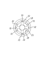
1例を図11〜図13に示し説明する。軸筒の後端などに嵌合されるノックキャップ101の天面102の縁部には、4つの貫通孔103が放射状に、等間隔に形成されている。その1つ1つの形状は、扇形をなしている。
また、前記隣り合う貫通孔103の軸線方向に於ける延長線上の、前記ノックキャップ101の円筒部105の内面には、軸筒などに嵌合する嵌合突部106が形成されている(図13参照)。即ち、前記貫通孔12の軸線方向に於ける延長線上の部分に、前記嵌合突部106が形成されている。
尚、前記天面102の中心部には、凹部107が形成されていて、その凹部107の中心部分が、射出成形の際樹脂が最初に入り込むゲート108になっている。
次に、前記ノックキャップ101を射出成形などの手段によって成形する際の、樹脂の流れについて説明する。前述したように、樹脂は、先ずゲート108から流れ、各連結部104に分散する。次いで、分散した樹脂は、円筒部105に流れ込むが、本例においては、連結部104が4箇所存在しているため、4箇所から流れ込む。この時、隣り合う連結部104から流れ込んだ各々の樹脂がぶつかり合い、ここに”ウエルド”と称されるつなぎ目のような模様が発生してしまうことがある。
尚、図中の矢印は、樹脂の流れを示すものである。
【0003】
【発明が解決しようとする課題】
ここで、前記嵌合突部106は、そのウエルド部分に形成されることになる。しかして、その嵌合突部106の近傍は、他の部分に比べ強度が弱く、コアピンを引き抜く際に無理に引き抜く力と相まって割れが発生してしまったり、また、成形品としても、軸筒と幾度となく着脱を繰り返しているうちに割れが発生し嵌合不良や、強いては、嵌合させることができなくなってしまう場合があった。
【0004】
【課題を解決するための手段】
本発明は、天面の少なくとも縁部近傍に貫通孔が形成され、前記天面の中心部を成形時のゲートとして射出成形で形成されたキャップであって、前記貫通孔の軸方向に於ける延長線上以外の部分に嵌合突部を形成すると共に、その嵌合突部が形成されたキャップをシャープペンシルの芯タンクの後端に着脱自在に外嵌したことを要旨とする。
【0005】
【作用】
嵌合突部以外の部分にウエルドが形成される。
【0006】
【実施例】
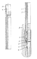
第1例を図1〜図4に示し説明する。軸筒1の内部には、複数の芯を収容する芯タンク2が摺動可能に配置されている。その芯タンク2の先端には、芯の把持・解放を行うチャック体3が固定されている。そのチャック体3の前方には、チャック体4の開閉を行うチャックリング4が囲繞している。
また、前記軸筒1の先端には、先部材5が螺着などの手段によって着脱自在に固定されており、その先部材5の内部には、芯の後退を阻止する芯戻り止め部6が一体形成されているが、別部材で構成し、圧入などの手段によって固定しても良い。符号7は、キャップであって、そのキャップ7には、クリップ8が一体形成されている。
一方、前記芯タンク2の後端は、軸筒1の後端から突出しており、その突出した内側部分には、消しゴム9が着脱自在に配置されており、また、その消しゴム9を覆うようにノックキャップ10が着脱自在に外嵌している。
【0007】
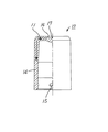
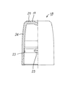
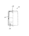
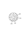
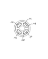
次に、前記ノックキャップ10について説明する。ノックキャップ10の天面11の縁部には、4つの貫通孔12が放射状に、等間隔に形成されている。その1つ1つの形状は、扇形をなしているが、丸型であっても三角型であっても良い。勿論、形成する貫通孔の数も、これに限定されるものではない。つまり、1つであっても良いし、小さな貫通孔を10個形成しても良い。
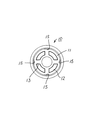
また、前記隣り合う貫通孔12の間に形成される連結部13の軸線方向に於ける延長線上の、前記ノックキャップ10の円筒部14の内面には、前記芯タンク2の後部に嵌合する嵌合突部15が形成されている(図4参照)。即ち、前記貫通孔12の中心軸線方向に於ける延長線上以外の部分に、前記嵌合突部15が形成されている。
尚、前記天面10の中心部には、凹部16が形成されていて、その凹部16の中心部分が、射出成形の際樹脂が最初に入り込むゲート17になっている。
【0008】
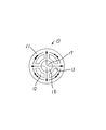
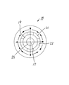
次に、前記ノックキャップ10を射出成形などの手段によって成形する際の、樹脂の流れについて説明する。前述したように、樹脂は、先ずゲート17から流れ、各連結部13に分散する。次いで、分散した樹脂は、円筒部14に流れ込むが、本例においては、連結部が4箇所存在しているため、4箇所から流れ込む(図2、図3参照:図中の矢印は、樹脂の流れを示すものである)。この時、隣り合う連結部13から流れ込んだ各々の樹脂がぶつかり合い、ここに”ウエルド”と称されるつなぎ目のような模様が発生してしまうことがある。さらに詳述すると、各連結部13から樹脂がほぼ均等に流れ込むため、前記のウエルドは、貫通孔12の中心軸線に於ける延長線上にほぼ形成される。尚、前記の嵌合突部15は、連結部13の軸線方向においてその延長線上に形成されるため、各々の連結部13から流れ込んだ各々の樹脂がぶつかり合う前に形成される。
【0009】
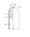
第2例を図5〜図7に示し説明する。前記第1例とほぼ同様であるが、本例のノックキャップ18の天面19には、円周状の溝20が形成されており、その溝部20に扇型をした貫通孔21と連結部22とが形成されている。また、嵌合突部23は、前例と同様に連結部22に於ける軸線方向の延長線上に形成されているが、筒状部24内面の中間部分に形成されている。符号25は、その中心部がゲート位置となる凹部である。
成形の際に発生するウエルドは、勿論、前記嵌合突部23以外の位置に形成される。
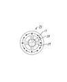
第3例を図8〜図10に示し説明する。ノックキャップ26の頂部には、半円弧状をした天面27が形成されている。勿論、この天面27にも貫通孔28と連結部29が形成されている。符号30は、ゲート位置となる凹部である。
また、ノックキャップ25の筒状部31の内面には、軸線方向に向かって嵌合突部32と没入防止用のリブ33が形成されている。前記嵌合突部32は、連結部22に於ける軸線方向の延長直線上に全て形成されているが、没入防止用のリブ33は、若干ずれた位置に形成されているものもある。しかし、ウエルドが発生する位置からは外れている。即ち、前記貫通孔28に於ける軸線方向の延長直線上から離れた位置に、前記リブ33が形成されている。
【0010】
【発明の効果】
本発明は、天面の少なくとも縁部近傍に貫通孔が形成され、前記天面の中心部を成形時のゲートとして射出成形で形成されたキャップであって、前記貫通孔の軸方向に於ける延長線上以外の部分に嵌合突部を形成すると共に、その嵌合突部が形成されたキャップをシャープペンシルの芯タンクの後端に着脱自在に外嵌したので、経時的に安定した嵌合力が得られるキャップを提供することができる。
【図面の簡単な説明】
【図1】 本発明の第1例を示す縦半断面図。
【図2】 図1のノックキャップの拡大図。
【図3】 図2の上面図。
【図4】 図2の底面図。
【図5】 第2例を示すノックキャップの縦半断面図。
【図6】 図5の上面図。
【図7】 図5の底面図。
【図8】 第3例を示すノックキャップの縦半断面図。
【図9】 図8の上面図。
【図10】 図8の底面図。
【図11】 従来のノックキャップを示す縦半断面図。
【図12】 図11の上面図。
【図13】 図11の底面図。
【符号の説明】
1 軸筒
2 芯タンク
3 チャック体
4 チャックリング
5 先部材
6 芯戻り止め部
7 キャップ
8 クリップ
9 消しゴム
10 ノックキャップ
11 天面
12 貫通孔
13 連結部
14 筒状部
15 嵌合突部
16 凹部
17 ゲート
18 ノックキャップ
19 天面
20 溝部
21 貫通孔
22 連結部
23 嵌合突部
24 筒状部
25 凹部
26 ノックキャップ
27 天面
28 貫通孔
29 連結部
30 凹部
31 筒状部
32 嵌合突部
33 没入防止用のリブ[0001]
BACKGROUND OF THE INVENTION
The present invention relates to a cap in which a through hole is formed at least near the edge of a top surface.
[0002]
[Prior art]
One example will be described with reference to FIGS. Four through
In addition, a
A
Next, the flow of resin when the
In addition, the arrow in a figure shows the flow of resin.
[0003]
[Problems to be solved by the invention]
Here, the
[0004]
[Means for Solving the Problems]
The present invention is formed at least near the edge to the through hole of the top surface, the a cap formed by injection molding as a gate at the time of molding the central portion of the top surface, in the axial direction of the through hole The gist is that a fitting protrusion is formed on a portion other than the extension line, and a cap on which the fitting protrusion is formed is detachably fitted to the rear end of the core tank of the mechanical pencil.
[0005]
[Action]
A weld is formed in a portion other than the fitting protrusion.
[0006]
【Example】
A first example will be described with reference to FIGS. A
Further, a
On the other hand, the rear end of the
[0007]
Next, the
Further, the inner surface of the
A
[0008]
Next, the flow of resin when the
[0009]
A second example will be described with reference to FIGS. Although it is substantially the same as the said 1st example, the circumferential groove |
Of course, the weld generated at the time of molding is formed at a position other than the
A third example will be described with reference to FIGS. A
Further, on the inner surface of the
[0010]
【The invention's effect】
The present invention is formed at least near the edge to the through hole of the top surface, the a cap formed by injection molding as a gate at the time of molding the central portion of the top surface, in the axial direction of the through hole A fitting protrusion is formed on the part other than the extension line, and the cap on which the protrusion is formed is detachably fitted to the rear end of the mechanical pencil core tank. Can be provided.
[Brief description of the drawings]
FIG. 1 is a longitudinal half sectional view showing a first example of the present invention.
FIG. 2 is an enlarged view of the knock cap of FIG.
FIG. 3 is a top view of FIG. 2;
4 is a bottom view of FIG. 2. FIG.
FIG. 5 is a longitudinal half sectional view of a knock cap showing a second example.
6 is a top view of FIG. 5;
7 is a bottom view of FIG. 5. FIG.
FIG. 8 is a longitudinal half sectional view of a knock cap showing a third example.
FIG. 9 is a top view of FIG.
10 is a bottom view of FIG. 8. FIG.
FIG. 11 is a longitudinal half sectional view showing a conventional knock cap.
12 is a top view of FIG.
13 is a bottom view of FIG.
[Explanation of symbols]
DESCRIPTION OF SYMBOLS 1
Claims (2)
Priority Applications (1)
| Application Number | Priority Date | Filing Date | Title |
|---|---|---|---|
| JP2000227975A JP4617543B2 (en) | 2000-07-27 | 2000-07-27 | cap |
Applications Claiming Priority (1)
| Application Number | Priority Date | Filing Date | Title |
|---|---|---|---|
| JP2000227975A JP4617543B2 (en) | 2000-07-27 | 2000-07-27 | cap |
Publications (2)
| Publication Number | Publication Date |
|---|---|
| JP2002036780A JP2002036780A (en) | 2002-02-06 |
| JP4617543B2 true JP4617543B2 (en) | 2011-01-26 |
Family
ID=18721353
Family Applications (1)
| Application Number | Title | Priority Date | Filing Date |
|---|---|---|---|
| JP2000227975A Expired - Lifetime JP4617543B2 (en) | 2000-07-27 | 2000-07-27 | cap |
Country Status (1)
| Country | Link |
|---|---|
| JP (1) | JP4617543B2 (en) |
Families Citing this family (4)
| Publication number | Priority date | Publication date | Assignee | Title |
|---|---|---|---|---|
| JP4745797B2 (en) * | 2005-11-09 | 2011-08-10 | ゼブラ株式会社 | Synthetic resin parts for writing instruments |
| JP5206318B2 (en) * | 2008-10-29 | 2013-06-12 | ぺんてる株式会社 | Side knock type writing instrument |
| JP6310210B2 (en) * | 2013-08-20 | 2018-04-11 | 三菱鉛筆株式会社 | Writing instrument |
| JP7677775B2 (en) * | 2020-11-02 | 2025-05-15 | 三菱鉛筆株式会社 | Cover member and writing implement equipped with cover member |
Family Cites Families (2)
| Publication number | Priority date | Publication date | Assignee | Title |
|---|---|---|---|---|
| JPH09226289A (en) * | 1996-02-27 | 1997-09-02 | Pentel Kk | Extra lead container |
| JPH11115375A (en) * | 1997-10-14 | 1999-04-27 | Kotobuki:Kk | Safety cap and liquid pen |
-
2000
- 2000-07-27 JP JP2000227975A patent/JP4617543B2/en not_active Expired - Lifetime
Also Published As
| Publication number | Publication date |
|---|---|
| JP2002036780A (en) | 2002-02-06 |
Similar Documents
| Publication | Publication Date | Title |
|---|---|---|
| JP4617543B2 (en) | cap | |
| US5000605A (en) | Ball point pen with tubular ball holder | |
| US4776718A (en) | Writing implement | |
| JP2593672Y2 (en) | Writing implement | |
| JP2607844Y2 (en) | Writing implement | |
| JP3648583B2 (en) | Temporary ink reservoir for writing instruments | |
| JP4042281B2 (en) | Writing instrument | |
| JP2001150870A (en) | Cap installing structure for writing utensil | |
| KR20030012497A (en) | Structure of cap for supplying oil | |
| CN222793085U (en) | A direct current marker pen | |
| JP2606975Y2 (en) | Ballpoint pen | |
| JP2581473Y2 (en) | Writing instrument cap | |
| JP2019104253A (en) | Writing instrument equipped with erasing component | |
| JP7575935B2 (en) | fountain pen | |
| JP4745797B2 (en) | Synthetic resin parts for writing instruments | |
| JP3275217B2 (en) | Ballpoint pen with ink backflow prevention mechanism | |
| JPWO2007063590A1 (en) | Filling writing instrument | |
| JP4657599B2 (en) | Parts molded by two-color molding or insert molding | |
| JP2000158883A (en) | Writing instrument tail plug | |
| JP6781573B2 (en) | Refill for writing instruments | |
| JP2549249Y2 (en) | Writing implement | |
| JPH0327818Y2 (en) | ||
| KR100466154B1 (en) | Ventmember of vulcanizing mold | |
| JP4386338B2 (en) | Writing instrument | |
| JPS5837674Y2 (en) | Shape pencil |
Legal Events
| Date | Code | Title | Description |
|---|---|---|---|
| A621 | Written request for application examination |
Free format text: JAPANESE INTERMEDIATE CODE: A621 Effective date: 20060628 |
|
| A977 | Report on retrieval |
Free format text: JAPANESE INTERMEDIATE CODE: A971007 Effective date: 20080326 |
|
| A131 | Notification of reasons for refusal |
Free format text: JAPANESE INTERMEDIATE CODE: A131 Effective date: 20090602 |
|
| A521 | Request for written amendment filed |
Free format text: JAPANESE INTERMEDIATE CODE: A523 Effective date: 20090803 |
|
| A131 | Notification of reasons for refusal |
Free format text: JAPANESE INTERMEDIATE CODE: A131 Effective date: 20100413 |
|
| A521 | Request for written amendment filed |
Free format text: JAPANESE INTERMEDIATE CODE: A523 Effective date: 20100610 |
|
| TRDD | Decision of grant or rejection written | ||
| A01 | Written decision to grant a patent or to grant a registration (utility model) |
Free format text: JAPANESE INTERMEDIATE CODE: A01 Effective date: 20100928 |
|
| A01 | Written decision to grant a patent or to grant a registration (utility model) |
Free format text: JAPANESE INTERMEDIATE CODE: A01 |
|
| A61 | First payment of annual fees (during grant procedure) |
Free format text: JAPANESE INTERMEDIATE CODE: A61 Effective date: 20101011 |
|
| FPAY | Renewal fee payment (event date is renewal date of database) |
Free format text: PAYMENT UNTIL: 20131105 Year of fee payment: 3 |
|
| R150 | Certificate of patent or registration of utility model |
Ref document number: 4617543 Country of ref document: JP Free format text: JAPANESE INTERMEDIATE CODE: R150 Free format text: JAPANESE INTERMEDIATE CODE: R150 |
|
| EXPY | Cancellation because of completion of term |