JP4617222B2 - Recording apparatus, recording method, and recording system - Google Patents
Recording apparatus, recording method, and recording system Download PDFInfo
- Publication number
- JP4617222B2 JP4617222B2 JP2005233285A JP2005233285A JP4617222B2 JP 4617222 B2 JP4617222 B2 JP 4617222B2 JP 2005233285 A JP2005233285 A JP 2005233285A JP 2005233285 A JP2005233285 A JP 2005233285A JP 4617222 B2 JP4617222 B2 JP 4617222B2
- Authority
- JP
- Japan
- Prior art keywords
- recording
- recording medium
- medium
- head
- mask pattern
- Prior art date
- Legal status (The legal status is an assumption and is not a legal conclusion. Google has not performed a legal analysis and makes no representation as to the accuracy of the status listed.)
- Expired - Fee Related
Links
Images


Description
本発明は、記録媒体に記録剤を付与することによって画像を記録する記録装置および記録方法に関する。 The present invention relates to a recording apparatus and a recording method for recording an image by applying a recording agent to a recording medium.
昨今、パーソナルコンピュータやワードプロセッサ等のOA機器が広く普及しており、これらの機器から出力された情報を多様な記録媒体に記録するための、様々な記録装置が提供されている。特に、インクジェット方式の記録装置は、低騒音、低ランニングコスト、小型な構成、およびカラー化が比較的容易である等、さまざまな優位点を有しており、幅広いユーザ層に受け入れられている。最近では、デジタルカメラで撮影した画像を、銀塩写真と同様な品位で出力することへの要求も高まっており、これに応えるための様々な工夫を取り入れた記録方法も実施されている。例えば、記録媒体の先端部あるいは後端部においては、記録装置の構成上、記録媒体の搬送精度が低下する傾向にある。これに対し、記録媒体の先端部あるいは後端部において特別な記録方法を採用したインクジェット記録装置が既に提供されている。 Recently, OA devices such as personal computers and word processors are widely used, and various recording devices for recording information output from these devices on various recording media are provided. In particular, the ink jet recording apparatus has various advantages such as low noise, low running cost, small size, and relatively easy colorization, and is accepted by a wide range of users. Recently, there has been an increasing demand for outputting images taken with a digital camera with the same quality as a silver halide photograph, and a recording method incorporating various ideas for responding to this has been implemented. For example, at the front end portion or the rear end portion of the recording medium, the conveyance accuracy of the recording medium tends to decrease due to the configuration of the recording apparatus. On the other hand, an ink jet recording apparatus that employs a special recording method at the front end portion or the rear end portion of the recording medium has already been provided.
以下に、「先後端部記録」について、その具体的な構成を簡単に説明する。 Hereinafter, the specific configuration of “front and rear end recording” will be briefly described.
(先後端部への記録について)
記録媒体の先端部あるいは後端部に対して記録する際、画像が乱れてしまう傾向がある。これは、記録ヘッドの上流側と下流側とから記録媒体を支えてこれを搬送する複数のローラ対の一部から、記録媒体が外れてしまう状況が生じることが主な原因となっている。以下、このような状態を、図面を用いて詳しく説明する。
(Recording on the front and rear ends)
When recording is performed on the front end portion or the rear end portion of the recording medium, the image tends to be disturbed. This is mainly due to a situation in which the recording medium is detached from some of the plurality of roller pairs that support and convey the recording medium from the upstream side and the downstream side of the recording head. Hereinafter, such a state will be described in detail with reference to the drawings.
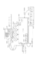
図1は、記録媒体の中央部分に対して記録を行っている状態の、記録ヘッドと記録媒体、および当該記録媒体を支えつつこれを搬送する搬送機構を模式的に示した図である。図1において、搬送ローラM3060と2つの排紙ローラM3100、M3110、およびこれらローラのそれぞれに対向するピンチローラM3070および拍車M3120は、3組のニップ部を形成し、記録媒体Pを張架および支持している。また、3つのローラが回転することにより、記録媒体Pは、図1の矢印で示した方向に搬送可能となっている。 FIG. 1 is a diagram schematically illustrating a recording head, a recording medium, and a conveyance mechanism that conveys the recording medium while supporting the recording medium in a state where recording is performed on a central portion of the recording medium. In FIG. 1, a conveyance roller M3060, two paper discharge rollers M3100 and M3110, and a pinch roller M3070 and a spur M3120 facing each of these rollers form three sets of nip portions to stretch and support the recording medium P. is doing. Further, by rotating the three rollers, the recording medium P can be conveyed in the direction indicated by the arrow in FIG.
H1000はヘッドカートリッジである。ヘッドカートリッジH1000には、インクを吐出するための複数の記録素子(ノズル)が、図1の搬送方向に所定のピッチで配列している。ヘッドカートリッジH1000は、図面の奥行き方向に走査しながら各記録素子よりインクを吐出し、搬送ローラM3060と排紙ローラM3100の間に位置している記録媒体Pの領域に対して、画像を形成する。このような、ヘッドカートリッジH1000による記録走査と、3つのローラ対による記録媒体Pの搬送動作とを交互に繰り返すことにより、記録媒体Pに順次画像が形成されていく。 H1000 is a head cartridge. In the head cartridge H1000, a plurality of recording elements (nozzles) for ejecting ink are arranged at a predetermined pitch in the transport direction of FIG. The head cartridge H1000 discharges ink from each recording element while scanning in the depth direction of the drawing, and forms an image on the area of the recording medium P located between the transport roller M3060 and the paper discharge roller M3100. . Images are sequentially formed on the recording medium P by alternately repeating the recording scanning by the head cartridge H1000 and the conveying operation of the recording medium P by the three roller pairs.
図2は、図1の状態から更に記録が進み、記録媒体Pの後端部近傍に対して記録を行っている状態を示した図である。記録媒体Pは、搬送ローラM3060から既に外れており、排紙ローラM3100、M3110のみの回転によって搬送されている。 FIG. 2 is a diagram showing a state in which recording further proceeds from the state of FIG. 1 and recording is performed on the vicinity of the rear end portion of the recording medium P. The recording medium P has already been removed from the conveyance roller M3060 and is conveyed by the rotation of only the paper discharge rollers M3100 and M3110.
ところで、一般に、搬送ローラM3060と排紙ローラM3100、M3110においては、その主な役割の違いから、ローラ径や搬送精度に若干の差が生じていることが多い。搬送ローラM3060については、記録走査ごとに、記録媒体を記録ヘッドに対する適切な位置に位置決めすることが主な役割である。よって、充分なローラ径を有し、所望の精度で搬送動作を行うことができる。これに対し、排紙ローラM3100、M3110は、記録後の記録媒体を確実に排出することが主な役割となっている。よって、搬送ローラM3060に比べて、ローラ径も小さく、記録媒体の搬送精度も劣っていることが多い。すなわち、記録媒体Pの後端部が搬送ローラM3060を外れた時点から、記録媒体Pの最後端部への記録が終了するまでの領域に対しては、それ以前の領域に比べて、搬送精度が低下している状況が生じてしまうのである。この際、記録する画像によっては、搬送量が不十分な場合には黒スジ、搬送量が多すぎる場合には白スジが確認され、無視できない画像弊害となる恐れがある。 By the way, generally, there are many differences between the roller diameter and the conveyance accuracy in the conveyance roller M3060 and the discharge rollers M3100 and M3110 due to the difference in main roles. As for the transport roller M3060, the main role is to position the recording medium at an appropriate position with respect to the recording head for each recording scan. Therefore, it has a sufficient roller diameter and can perform a transport operation with a desired accuracy. On the other hand, the paper discharge rollers M3100 and M3110 have a main role of reliably discharging the recording medium after recording. Therefore, the roller diameter is small and the conveyance accuracy of the recording medium is often inferior compared to the conveyance roller M3060. In other words, compared to the previous area, the conveyance accuracy for the area from when the rear end of the recording medium P is removed from the conveying roller M3060 to when the recording on the last end of the recording medium P is completed. The situation is that the decline is occurring. At this time, depending on the image to be recorded, a black streak is confirmed when the transport amount is insufficient, and a white streak is confirmed when the transport amount is too large, which may cause an image problem that cannot be ignored.
更に、記録媒体の両端部が保持されていないことによる画像弊害も発生する。記録媒体Pの後端部が、搬送ローラM3060を外れると、記録ヘッドと記録媒体との距離(以下、紙間距離と称する)は少なからず変動し、その後も不安定な状態となる。インクジェット記録ヘッドは、前後のローラによって維持される所定の紙間距離に応じたタイミングでインクを吐出しながら移動している。そして、適切なタイミングで吐出されたインクが、記録媒体上でドットとなり、適切なピッチで配列することによって画像が形成されている。よって、記録の最中に紙間距離が変更されたり、その後の紙間距離の変動が大きかったりすると、記録媒体におけるドットの位置も不安定になり、白スジや黒スジあるいはザラツキ感などの画像弊害が発生するのである。このような紙間距離の問題は、記録媒体の後端部のみならず、先端部に対して記録する場合にも同様に発生する。 In addition, image defects due to the fact that both ends of the recording medium are not held also occur. When the rear end of the recording medium P is out of the conveying roller M3060, the distance between the recording head and the recording medium (hereinafter referred to as the inter-paper distance) fluctuates not a little, and thereafter it becomes unstable. The ink jet recording head moves while ejecting ink at a timing corresponding to a predetermined inter-paper distance maintained by the front and rear rollers. The ink ejected at an appropriate timing becomes dots on the recording medium, and an image is formed by arranging the ink at an appropriate pitch. Therefore, if the paper-to-paper distance is changed during recording or the paper-to-paper distance fluctuates thereafter, the dot position on the recording medium becomes unstable, and images such as white lines, black lines, or rough feeling Detriment will occur. Such a problem of the inter-paper distance similarly occurs when recording not only on the rear end portion of the recording medium but also on the front end portion.
図3は、記録媒体Pの先端部近傍に対して記録を行っている状態を示した図である。記録媒体Pは、搬送ローラM3060のみによって保持され、搬送されている。先端部の記録の場合、記録媒体Pの搬送は排紙ローラM3100、M3110ではなく、搬送ローラM3060によって行われている。よって、図2で説明した後端部近傍を記録する状態に比べれば、より高い精度で搬送が成されている。しかし、記録媒体Pの先端が保持されていないことによる紙間距離の問題は、図2の状態と同等である。すなわち、記録媒体におけるドットの位置精度は、記録媒体中央部への記録に比べて不安定になっている。 FIG. 3 is a diagram illustrating a state where recording is performed on the vicinity of the front end of the recording medium P. The recording medium P is held and transported only by the transport roller M3060. In the case of recording at the leading edge, the recording medium P is conveyed not by the discharge rollers M3100 and M3110 but by the conveyance roller M3060. Therefore, compared with the state where the vicinity of the rear end portion described in FIG. 2 is recorded, the conveyance is performed with higher accuracy. However, the problem of the inter-paper distance due to the fact that the leading edge of the recording medium P is not held is equivalent to the state of FIG. That is, the positional accuracy of the dots on the recording medium is unstable compared to the recording on the central part of the recording medium.
以上のような記録媒体の先端部および後端部での画像問題に対し、特に画像品位を重視するシリアル型の記録装置においては、先後端部でのみ記録ヘッドの記録幅(すなわち、実際にインクを吐出する記録素子の数)を抑制し、これに合わせて記録媒体の搬送量も低減する方法が採用されている(例えば特許文献1参照。)。記録ヘッドの記録幅を狭くすることにより、記録幅に対する紙間距離の変動を抑えることが出来る。この場合、特に後述するマルチパス記録を実施した際のザラツキに対し効果が発揮される。また、搬送精度が低下した状況においても、記録媒体の搬送量を小さくすることにより、その搬送誤差を小さくすることが出来る。更につなぎ部分のピッチが細かくなることとも相俟って、白スジや黒スジが目立たなくなるという効果もある。 In order to deal with the image problems at the leading end and the trailing end of the recording medium as described above, in a serial type recording apparatus in which image quality is particularly important, the recording width of the recording head (that is, the ink actually (The number of recording elements that discharge ink) is reduced, and a method of reducing the conveyance amount of the recording medium in accordance with this is adopted (see, for example, Patent Document 1). By narrowing the recording width of the recording head, fluctuations in the inter-paper distance with respect to the recording width can be suppressed. In this case, an effect is particularly exerted against roughness when multipass printing described later is performed. Even in a situation where the conveyance accuracy is reduced, the conveyance error can be reduced by reducing the conveyance amount of the recording medium. Further, coupled with the fact that the pitch of the connecting portion becomes fine, there is an effect that white stripes and black stripes become inconspicuous.
また、記録素子の配列密度が記録密度よりも低い形態の記録ヘッドを用い、複数の記録走査で副走査方向の記録密度を補間しながら画像を完成させていくインターレース記録方法を採用するインクジェット記録装置においても、やはり先後端部でのみ実際にインクを吐出する記録素子の数を抑制し、これに合わせて記録媒体の搬送量を調整する方法が採用されている(例えば、特許文献2参照。)。
しかしながら、従来の記録方法においては、記録媒体の先後端部への記録の際に使用するノズル数を中央部分への記録の際に比べて低減する場合に、その低減の割合を記録モードによらず一定にしていた。つまり、高速モードにおいても、高品位モードと同程度に使用ノズル数を絞っていた。このために、高速モードにおける先後端部に対する記録時間が比較的長くなってしまっていた。 However, in the conventional recording method, when the number of nozzles used for recording on the front and rear end portions of the recording medium is reduced as compared with the recording on the central portion, the reduction ratio depends on the recording mode. It was constant. That is, in the high speed mode, the number of used nozzles is reduced to the same extent as in the high quality mode. For this reason, the recording time for the front and rear ends in the high-speed mode has become relatively long.
本発明は、以上のような課題に鑑みてなされたものであり、その目的とするところは、複数の記録モードに応じて記録媒体の先後端部への記録に用いるノズルの数を適切に切り替えられることにより、画像品位と記録時間のバランスのとれた出力が可能な記録装置および記録方法を提供することである。 The present invention has been made in view of the above-described problems, and an object of the present invention is to appropriately switch the number of nozzles used for recording on the front and rear end portions of a recording medium according to a plurality of recording modes. Accordingly, it is an object of the present invention to provide a recording apparatus and a recording method capable of outputting an image with a good balance between image quality and recording time.
そのための本発明は、記録剤を付与するための記録素子が所定の方向に配列された記録ヘッドを前記所定の方向と異なる方向に走査しながら前記記録ヘッドにより前記記録剤を記録媒体に付与する記録動作と、前記走査の方向とは異なる方向に前記記録媒体を搬送する搬送動作とを繰り返すことにより、前記記録媒体に画像を記録する記録装置であって、前記記録ヘッドより上流側に位置し前記記録媒体を支持および搬送する上流側の搬送手段と、前記記録ヘッドより下流側に位置し前記記録媒体を支持および搬送する下流側の搬送手段と、前記記録媒体が前記上流側の搬送手段によってのみ支持および搬送されている場合には、前記先端部に対する記録と判断し、前記記録媒体が前記上流側および下流側の搬送手段によって支持および搬送されている場合には、前記中央部に対する記録と判断し、前記記録媒体が前記下流側の搬送手段によってのみ支持および搬送されている場合には、前記後端部に対する記録と判断する判断手段と、前記中央部に対する記録に用いる記録素子の数に比して、前記先端部および前記後端部の少なくとも一方の端部に対する記録に用いる記録素子の数を低減させて前記記録動作を実行する記録制御手段を備え、前記記録制御手段は、前記画像の記録品位あるいは記録時間が異なる複数の記録モードの中から選択される記録モードに応じて、前記低減の割合を異ならせることを特徴とする。 For this purpose, the present invention applies the recording agent to the recording medium by the recording head while scanning a recording head in which recording elements for applying the recording agent are arranged in a predetermined direction in a direction different from the predetermined direction. A recording apparatus that records an image on the recording medium by repeating a recording operation and a conveying operation that conveys the recording medium in a direction different from the scanning direction, and is located upstream of the recording head. An upstream conveying unit that supports and conveys the recording medium; a downstream conveying unit that is located downstream of the recording head and supports and conveys the recording medium; and the recording medium is formed by the upstream conveying unit. When the recording medium is only supported and transported, it is determined that the recording is performed on the leading end, and the recording medium is supported and transported by the upstream and downstream transporting means. The recording unit determines that the recording is performed on the central portion, and the recording medium determines that the recording is performed on the rear end when the recording medium is supported and transported only by the transporting unit on the downstream side. , compared to the number of recording elements used in recording for the previous SL in central portion, the recording operation by reducing the number of printing elements used for printing for at least one end portion of the front Kisaki end and the rear end portion Recording control means for executing the above-mentioned, wherein the recording control means varies the reduction ratio according to a recording mode selected from a plurality of recording modes having different recording quality or recording time of the image. Features.
また、本発明は、記録剤を付与するための記録素子が所定の方向に配列された記録ヘッドを前記所定の方向と異なる方向に走査しながら前記記録ヘッドから記録媒体に前記記録剤を付与することにより、前記記録媒体に記録を行う記録装置であって、前記記録ヘッドより上流側に位置し前記記録媒体を支持および搬送する上流側の搬送手段と、前記記録ヘッドより下流側に位置し前記記録媒体を支持および搬送する下流側の搬送手段と、前記記録媒体が前記上流側の搬送手段によってのみ支持および搬送されている場合には、前記先端部に対する記録と判断し、前記記録媒体が前記上流側および下流側の搬送手段によって支持および搬送されている場合には、前記中央部に対する記録と判断し、前記記録媒体が前記下流側の搬送手段によってのみ支持および搬送されている場合には、前記後端部に対する記録と判断する判断手段と、画像の記録品位あるいは記録時間が異なる複数の記録モードの中から実行すべき1つの記録モードを設定するための設定手段と、前記設定手段により設定された記録モードに応じた数の記録素子を用いて前記中央部に対して記録を行う手段と、前記設定手段により設定された記録モードに応じた数の記録素子であって、前記記録媒体の中央部で使用される記録素子の数よりも少ない数の記録素子を用いて、前記先端部および前記後端部の少なくとも一方に対して記録を行う手段とを備え、前記中央部に対する記録において使用される記録素子の数と前記先端部および後端部の少なくとも一方に対する記録において使用される記録素子の数との比が、前記設定手段によって設定される記録モードの種類によって異なることを特徴とする。 Further, the present invention applies the recording agent from the recording head to a recording medium while scanning a recording head in which recording elements for applying the recording agent are arranged in a predetermined direction in a direction different from the predetermined direction. Thus, a recording apparatus for recording on the recording medium, the upstream conveying means for supporting and conveying the recording medium located upstream from the recording head, and located downstream from the recording head When the recording medium is supported and conveyed only by the conveying means on the downstream side that supports and conveys the recording medium, and the recording medium is supported and conveyed only by the conveying means on the upstream side, the recording medium is determined to be recorded, and the recording medium is When supported and transported by upstream and downstream transport means, it is determined that the recording is performed on the central portion, and the recording medium is transported by the downstream transport means. If it is seen supported and transported, set determining means for determining a recording, one recording mode to be executed from among the recording quality or the recording time is different from a plurality of recording modes of an image for the rear portion setting means for, and means for recording on central unit before Symbol in using the recording elements of a number corresponding to the set print mode by said setting means, according to the recording mode set by said setting means a number of the recording element, using the number of recording elements less than the number of recording elements used in the central portion of the recording medium, to at least one of the front Kisaki end and the rear end portion Means for recording, and the ratio of the number of recording elements used in recording to the central portion and the number of recording elements used in recording to at least one of the leading end portion and the trailing end portion is Wherein the different depending on the type of the recording mode set by the setting means.
また、本発明は、記録剤を付与するための記録素子が所定の方向に配列された記録ヘッドを前記所定の方向と異なる方向に走査しながら前記記録ヘッドにより前記記録剤を記録媒体に付与する記録動作と、前記記録ヘッドより上流側に位置し前記記録媒体を支持および搬送する上流側の搬送手段および前記記録ヘッドより下流側に位置し前記記録媒体を支持および搬送する下流側の搬送手段により前記走査の方向とは異なる方向に前記記録媒体を搬送する搬送動作とを繰り返すことにより、前記記録媒体に画像を記録する記録方法であって、前記記録媒体が前記上流側の搬送手段によってのみ支持および搬送されている場合には、前記先端部に対する記録と判断し、前記記録媒体が前記上流側および下流側の搬送手段によって支持および搬送されている場合には、前記中央部に対する記録と判断し、前記記録媒体が前記下流側の搬送手段によってのみ支持および搬送されている場合には、前記後端部に対する記録と判断する判断工程と、前記画像の記録品位あるいは記録時間が互いに異なる複数の記録モードの中から実行すべき1つの記録モードを設定する設定工程と、前記設定工程において設定された記録モードに応じた数の記録素子を用いて、前記中央部に対して記録を行う第1の記録工程と、前記設定工程において設定された記録モードに応じた数の記録素子であって、前記第1の記録工程で使用される記録素子の数よりも少ない数の記録素子を用いて、前記先端部および前記後端部の少なくとも一方に対して記録を行う第2の記録工程とを有し、前記第1の記録工程で使用される記録素子の数に対する前記第2の記録工程で使用される記録素子の数の割合は、前記設定工程において設定される記録モードの種類によって異なることを特徴とする。 According to the present invention, the recording agent is applied to the recording medium by the recording head while scanning a recording head in which recording elements for applying the recording agent are arranged in a predetermined direction in a direction different from the predetermined direction. A recording operation, an upstream conveying unit positioned upstream of the recording head and supporting and conveying the recording medium; and a downstream conveying unit positioned downstream of the recording head and supporting and conveying the recording medium. A recording method for recording an image on the recording medium by repeating a conveying operation for conveying the recording medium in a direction different from the scanning direction, wherein the recording medium is supported only by the upstream conveying means. If the recording medium is transported, it is determined that the recording is performed on the leading end, and the recording medium is supported and transported by the upstream and downstream transporting means Determining that the recording is performed on the central portion, and determining that the recording medium is recording on the rear end portion when the recording medium is supported and transported only by the downstream transport unit; a setting step of recording quality or a recording time of the image sets one recording mode to be executed from among a plurality of different recording modes, the number of recording elements according to the recording mode set in the setting step used, a first recording step for recording on pre SL in central portion, a recording element number corresponding to the recording mode set in the setting step, is used in the first recording step with the number of printing elements less than the number of recording elements that, before and a second recording step for recording on at least one of Kisaki end and the rear end portion, the first recording Used in the process The ratio of the number of recording elements used in the second recording process to the number of recording elements is characterized in that it varies depending on the kinds of the recording mode set in the setting step.
また、本発明は、記録剤を付与するための記録素子が所定の方向に配列された記録ヘッドを前記所定の方向と異なる方向に走査しながら前記記録ヘッドから記録媒体に前記記録剤を付与することにより前記記録媒体に記録を行う記録装置と、前記記録装置を制御するためのホスト装置とを含む記録システムであって、前記記録ヘッドより上流側に位置し前記記録媒体を支持および搬送する上流側の搬送手段と、前記記録ヘッドより下流側に位置し前記記録媒体を支持および搬送する下流側の搬送手段と、前記記録媒体が前記上流側の搬送手段によってのみ支持および搬送されている場合には、前記先端部に対する記録と判断し、前記記録媒体が前記上流側および下流側の搬送手段によって支持および搬送されている場合には、前記中央部に対する記録と判断し、前記記録媒体が前記下流側の搬送手段によってのみ支持および搬送されている場合には、前記後端部に対する記録と判断する判断手段と、画像の記録品位あるいは記録時間が異なる複数の記録モードの中から実行すべき1つの記録モードを設定するための設定手段と、前記設定手段により設定された記録モードに応じた数の記録素子を用いて前記記録媒体の中央部に対して記録を行う手段と、前記設定手段により設定された記録モードに応じた数の記録素子であって、前記中央部で使用される記録素子の数よりも少ない数の記録素子を用いて、前記先端部および前記後端部に対して記録を行う手段とを備え、前記中央部に対する記録において使用される記録素子の数と前記先端部および後端部の少なくとも一方に対する記録において使用される記録素子の数との比が、前記設定手段によって設定される記録モードの種類によって異なることを特徴とする。 Further, the present invention applies the recording agent from the recording head to a recording medium while scanning a recording head in which recording elements for applying the recording agent are arranged in a predetermined direction in a direction different from the predetermined direction. A recording system including a recording device for recording on the recording medium and a host device for controlling the recording device, wherein the upstream is located upstream from the recording head and supports and conveys the recording medium Side conveying means, downstream conveying means positioned downstream of the recording head and supporting and conveying the recording medium, and when the recording medium is supported and conveyed only by the upstream conveying means If the recording medium is supported and transported by the upstream and downstream transporting means, it is determined that the recording is performed on the leading end. That record and determines, when said recording medium is only supported and conveyed by the conveying means of said downstream side determination means for determining a recording on the trailing end, the recording quality or a recording time of the image are different A setting unit for setting one recording mode to be executed from among a plurality of recording modes, and a number of recording elements corresponding to the recording mode set by the setting unit are used for the central portion of the recording medium. using means for performing recording, a number of recording elements according to the set print mode by the setting unit, the recording element number less than the number of recording elements used in the previous SL in central portion Te , before and means for recording on Kisaki end and the rear end portion, the serial to at least one of the number and the tip and rear ends of the recording elements used in recording on the central portion The ratio between the number of recording elements used in, characterized in different depending on the type of the recording mode set by said setting means.
本発明によれば、記録モードに応じて、記録媒体の先後端部への記録に用いるノズル数を適切に切り替えるため、先後端部においても、ユーザの意図に応じた品位と記録時間で画像を出力することができる。 According to the present invention, in order to appropriately switch the number of nozzles used for recording on the front and rear end portions of the recording medium according to the recording mode, an image can be displayed at the front and rear end portions with a quality and recording time according to the user's intention. Can be output.
以下に、本発明の実施形態を詳細に説明する。まず、本実施形態で適用するインクジェット記録装置の本体構成を説明する。 Hereinafter, embodiments of the present invention will be described in detail. First, the main body configuration of the ink jet recording apparatus applied in the present embodiment will be described.
(機構部の構成)
本実施形態における記録装置本体は、各機構の役割から、給紙部、用紙搬送部、排紙部、キャリッジ部、クリーニング部および外装部に分類することができる。以下、これらを項目別に概略を説明していく。
(Mechanical structure)
The recording apparatus main body according to the present embodiment can be classified into a paper feed unit, a paper transport unit, a paper discharge unit, a carriage unit, a cleaning unit, and an exterior unit according to the role of each mechanism. Hereinafter, these will be outlined by item.
(A)給紙部
図16および図17は、本実施形態で適用する記録装置の斜視図であり、図16は記録装置の非使用状態、図17は記録装置M1の使用状態をそれぞれ示している。また、図18、図19および図20は、記録装置本体の内部機構を説明するための図であり、図18は右上部からの斜視図、図19は左上部からの斜視図および図20は記録装置本体の側断面図をそれぞれ示したものである。
(A) Paper Feed Unit FIGS. 16 and 17 are perspective views of a recording apparatus applied in this embodiment. FIG. 16 shows a non-use state of the recording apparatus, and FIG. 17 shows a use state of the recording apparatus M1. Yes. 18, 19 and 20 are diagrams for explaining the internal mechanism of the recording apparatus main body. FIG. 18 is a perspective view from the upper right portion, FIG. 19 is a perspective view from the upper left portion, and FIG. 2 is a side sectional view of the recording apparatus main body.
図16〜図20を参照するに、給紙部は記録媒体を積載する圧板M2010、記録媒体を1枚ずつ給紙する給紙ローラM2080、記録媒体を分離する分離ローラM2041、記録媒体を積載位置に戻す為の戻しレバーM2020、等がベースM2000に取り付けられる構成となっている。 Referring to FIGS. 16 to 20, the sheet feeding unit is a pressure plate M2010 for stacking recording media, a sheet feeding roller M2080 for feeding recording media one by one, a separation roller M2041 for separating recording media, and a stacking position for recording media. A return lever M2020, etc. for returning to the base M2000 is attached to the base M2000.
ベースM2000または外装には、積載された記録媒体を保持する為の給紙トレイM2060が取り付けられている。給紙トレイM2060は多段式で使用時は回転させて用いるものである。 A paper feed tray M2060 for holding a stacked recording medium is attached to the base M2000 or the exterior. The paper feed tray M2060 is a multistage type and is rotated when used.
給紙ローラM2080は、断面円弧の棒状をしている。用紙基準よりに1つの分離ローラゴムが設けられており、これによって記録媒体を給紙する。給紙ローラM2080の駆動力は、給紙部に設けられた専用ASFモータE0105から不図示の駆動伝達ギア、遊星ギアによって伝達される。 The feed roller M2080 has a bar shape with a circular arc in cross section. One separation roller rubber is provided based on the sheet reference, and the recording medium is fed by this. The driving force of the paper feeding roller M2080 is transmitted from a dedicated ASF motor E0105 provided in the paper feeding unit by a drive transmission gear and a planetary gear (not shown).
圧板M2010には可動サイドガイドM2030が移動可能に設けられて、記録媒体の積載位置を規制している。圧板M2010はベースM2000に結合された回転軸を中心に回転可能で、圧板ばねM2012により給紙ローラM2080に付勢される。給紙ローラM2080と対向する圧板M2010の部位には、枚数が残り少なくなった状態での記録媒体の重送を防止するために、人工皮等の摩擦係数の大きい材質からなる分離シートM2013が設けられている。圧板M2010は、圧板カムによって、給紙ローラM2080に、当接、離間できるように構成されている。 A movable side guide M2030 is movably provided on the pressure plate M2010 to restrict the recording medium stacking position. The pressure plate M2010 can rotate around a rotation shaft coupled to the base M2000, and is urged by the pressure plate spring M2012 to the paper feed roller M2080. A separation sheet M2013 made of a material having a large coefficient of friction such as an artificial skin is provided at a portion of the pressure plate M2010 facing the sheet feeding roller M2080 in order to prevent double feeding of the recording medium when the number of remaining sheets is small. ing. The pressure plate M2010 can be brought into contact with and separated from the paper feed roller M2080 by a pressure plate cam.
ベースM2000には、記録媒体を一枚ずつ分離するための分離ローラM2041を取り付けた分離ローラホルダM2040が、ベースM2000に設けられた回転軸を中心に回転可能に設置され、不図示の分離ローラバネにより給紙ローラM2080に付勢されている。分離ローラM2041には、不図示のクラッチが取り付けられており、所定以上の負荷がかかると、分離ローラM2041が取り付けられた部分が、回転する構成になっている。分離ローラM2041は、分離ローラリリースシャフトM2044と不図示のコントロールカムによって、給紙ローラM2080に、当接、離間できるように構成されている。これら圧板M2010、戻しレバーM2020、および分離ローラM2041の位置は、オートシートフィードセンサ(以下ASFセンサと言う)E0009によって検知されている。 In the base M2000, a separation roller holder M2040 to which a separation roller M2041 for separating the recording media one by one is attached so as to be rotatable around a rotation shaft provided in the base M2000, and is separated by a separation roller spring (not shown). The sheet is fed to the sheet feeding roller M2080. A clutch (not shown) is attached to the separation roller M2041, and the portion to which the separation roller M2041 is attached rotates when a load exceeding a predetermined value is applied. The separation roller M2041 is configured to be able to abut against and separate from the paper feed roller M2080 by a separation roller release shaft M2044 and a control cam (not shown). The positions of the pressure plate M2010, the return lever M2020, and the separation roller M2041 are detected by an auto sheet feed sensor (hereinafter referred to as an ASF sensor) E0009.
記録媒体を積載位置に戻す為の戻しレバーM2020は、回転可能にベースM2000に取り付けられており、解除方向に不図示の戻しレバーバネで付勢されている。記録媒体を戻す時は、コントロールカムによって回転するように構成されている。 A return lever M2020 for returning the recording medium to the loading position is rotatably attached to the base M2000 and is urged by a return lever spring (not shown) in the release direction. When the recording medium is returned, the recording medium is rotated by a control cam.
以上の構成を用いて給紙する状態を以下に説明する。 A state of feeding paper using the above configuration will be described below.
通常の待機状態において、圧板M2010は圧板カムでリリースされ、分離ローラM2041はコントロールカムでリリースされている。また、戻しレバーM2020は記録媒体を戻し、積載状態の記録媒体が奥に入らないように、積載口を塞ぐような積載位置に設けられている。 In a normal standby state, the pressure plate M2010 is released by the pressure plate cam, and the separation roller M2041 is released by the control cam. The return lever M2020 is provided at a stacking position that closes the stacking port so that the recording medium is returned and the stacked recording medium does not enter the back.
給紙を行う際には、まずモータ駆動によって、分離ローラM2041が給紙ローラM2080に当接する。そして、戻しレバーM2020がリリースされて、圧板M2010が給紙ローラM2080に当接する。この状態で、記録媒体の給紙が開始される。記録媒体は、ベースM2000に設けられた不図示の前段分離部で制限され、記録媒体の所定枚数のみが給紙ローラM2080と分離ローラM2041から構成されるニップ部に送られる。送られた記録媒体はニップ部で分離され、最上位の記録媒体のみが搬送される。 When feeding paper, first, the separation roller M2041 contacts the paper feeding roller M2080 by driving the motor. Then, the return lever M2020 is released, and the pressure plate M2010 comes into contact with the paper feed roller M2080. In this state, feeding of the recording medium is started. The recording medium is limited by a pre-stage separation unit (not shown) provided on the base M2000, and only a predetermined number of recording media is sent to a nip portion composed of a paper feed roller M2080 and a separation roller M2041. The sent recording medium is separated at the nip portion, and only the uppermost recording medium is conveyed.
記録媒体が、搬送ローラM3060およびピンチローラM3070まで到達すると、圧板M2010は不図示の圧板カムによって、分離ローラM2041はコントロールカムによって、リリースされる。戻しレバーM2020は、コントロールカムによって積載位置に戻る。これにより、給紙ローラM2080と分離ローラM2041とから構成されるニップ部に到達していた記録媒体は積載位置まで戻される。 When the recording medium reaches the conveyance roller M3060 and the pinch roller M3070, the pressure plate M2010 is released by a pressure plate cam (not shown), and the separation roller M2041 is released by a control cam. The return lever M2020 is returned to the loading position by the control cam. As a result, the recording medium that has reached the nip portion formed by the paper feed roller M2080 and the separation roller M2041 is returned to the stacking position.
(B)用紙搬送部
曲げ起こした板金からなるシャーシM1010には、記録媒体を搬送する搬送ローラM3060とペーパエンドセンサ(以下PEセンサと称す)E0007が回動可能に取り付けられている。搬送ローラM3060は、金属軸の表面にセラミックの微小粒がコーティングされた構成となっており、両軸の金属部分を不図示の軸受けが受ける状態で、シャーシM1010に取り付けられている。軸受けと搬送ローラM3060との間には、不図示のローラテンションバネが設けられており、搬送ローラM3060を付勢することにより、回転時に適量の負荷を与えて安定した搬送が行えるようになっている。
(B) Paper Conveying Unit A conveyance roller M3060 for conveying a recording medium and a paper end sensor (hereinafter referred to as a PE sensor) E0007 are rotatably attached to a chassis M1010 made of a bent metal sheet. The conveying roller M3060 has a structure in which ceramic fine particles are coated on the surface of a metal shaft, and is attached to the chassis M1010 in a state where the metal portions of both shafts are received by bearings (not shown). A roller tension spring (not shown) is provided between the bearing and the conveyance roller M3060. By energizing the conveyance roller M3060, an appropriate amount of load is applied during rotation so that stable conveyance can be performed. Yes.
搬送ローラM3060には、従動する複数のピンチローラM3070が当接して設けられている。ピンチローラM3070は、ピンチローラホルダM3000に保持されているが、不図示のピンチローラバネによって付勢されることで、搬送ローラM3060に圧接し、ここで記録媒体の搬送力を生み出している。この時、ピンチローラホルダM3000の回転軸は、シャーシM1010の軸受けに取り付けられ、この位置を中心に回転する。 A plurality of driven pinch rollers M3070 are provided in contact with the transport roller M3060. The pinch roller M3070 is held by the pinch roller holder M3000, but is urged by a pinch roller spring (not shown) to be brought into pressure contact with the conveyance roller M3060, and generates a conveyance force for the recording medium. At this time, the rotation shaft of the pinch roller holder M3000 is attached to the bearing of the chassis M1010 and rotates around this position.
記録媒体が搬送されてくる入口には、記録媒体をガイドするためのペーパガイドフラッパM3030およびプラテンM3040が配設されている。また、ピンチローラホルダM3000には、PEセンサレバーM3021が設けられており、PEセンサレバーM3021は、記録媒体の先端および後端の検出をPEセンサ−E0007に伝える役割を果たす。プラテンM3040は、シャーシM1010に取り付けられ、位置決めされている。ペーパガイドフラッパM3030は、不図示の軸受け部を中心に回転可能で、シャーシM1010に当接することで位置決めされる。また、軸受け部は、搬送ローラM3060と嵌合して摺動する。 A paper guide flapper M3030 and a platen M3040 for guiding the recording medium are disposed at the entrance where the recording medium is conveyed. The pinch roller holder M3000 is provided with a PE sensor lever M3021, and the PE sensor lever M3021 plays a role of transmitting the detection of the leading edge and the trailing edge of the recording medium to the PE sensor-E0007. The platen M3040 is attached to the chassis M1010 and positioned. The paper guide flapper M3030 can rotate around a bearing portion (not shown) and is positioned by contacting the chassis M1010. Further, the bearing portion slides in engagement with the transport roller M3060.
搬送ローラM3060の記録媒体搬送方向における下流側には、不図示の記録ヘッドH1001が設けられている。 A recording head H1001 (not shown) is provided on the downstream side of the conveyance roller M3060 in the recording medium conveyance direction.
上記構成における搬送の過程を説明する。用紙搬送部に送られた記録媒体は、ピンチローラホルダM3000及びペーパガイドフラッパM3030に案内されて、搬送ローラM3060とピンチローラM3070とのローラ対に送られる。この時、PEセンサレバーM3021が、記録媒体の先端を検知して、これにより記録媒体に対する記録位置が求められている。搬送ローラM3060とピンチローラM3070とからなるローラ対は、LFモータE0002の駆動により回転され、この回転により記録媒体がプラテンM3040上を搬送される。プラテンM3040には、搬送基準面となるリブが形成されており、このリブにより、記録ヘッドH1001と記録媒体表面との間のギャップが管理されている。また同時に、当該リブが、後述する排紙部と合わせて、記録媒体の波打ちを抑制する役割も果たしている。またプラテンM3040上には不図示のスポンジ部が設けられており、記録媒体の先端部、後端部の記録時には前記スポンジ部に対応する位置のノズルを使用して画像の形成を行う。 The conveyance process in the above configuration will be described. The recording medium sent to the paper transport unit is guided by the pinch roller holder M3000 and the paper guide flapper M3030, and is sent to the roller pair of the transport roller M3060 and the pinch roller M3070. At this time, the PE sensor lever M3021 detects the leading edge of the recording medium, and thereby the recording position with respect to the recording medium is obtained. A roller pair composed of a conveyance roller M3060 and a pinch roller M3070 is rotated by driving of the LF motor E0002, and the recording medium is conveyed on the platen M3040 by this rotation. The platen M3040 is provided with a rib serving as a conveyance reference surface, and a gap between the recording head H1001 and the recording medium surface is managed by the rib. At the same time, the ribs play a role of suppressing the undulation of the recording medium together with a paper discharge unit described later. Further, a sponge part (not shown) is provided on the platen M3040, and an image is formed using a nozzle at a position corresponding to the sponge part at the time of recording at the front end part and the rear end part of the recording medium.
搬送ローラM3060が回転するための駆動力は、例えばDCモータからなるLFモータE0002の回転力が、不図示のタイミングベルトを介して、搬送ローラM3060の軸上に配設されたプーリM3061に伝達されることによって得られている。また、搬送ローラM3060の軸上には、搬送ローラM3060による搬送量を検出する為のコードホイールM3062が設けられており、隣接するシャーシM1010には、コードホイールM3062に形成されたマーキングを読み取るためのエンコードセンサM3090が配設されている。尚、コードホイールM3062に形成されたマーキングは、150〜300lpi(ライン/インチ)のピッチで形成されているものとする。 The driving force for rotating the transport roller M3060 is transmitted, for example, to the pulley M3061 provided on the shaft of the transport roller M3060 via a timing belt (not shown) from the LF motor E0002 made of a DC motor. It is obtained by doing. Further, a code wheel M3062 for detecting the amount of conveyance by the conveyance roller M3060 is provided on the axis of the conveyance roller M3060, and an adjacent chassis M1010 is used for reading a marking formed on the code wheel M3062. An encode sensor M3090 is provided. The markings formed on the code wheel M3062 are formed at a pitch of 150 to 300 lpi (line / inch).
(C)排紙部
排紙部は、第1の排紙ローラM3100および第2の排紙ローラM3110、複数の拍車M3120およびギア列などから構成されている。
(C) Paper Discharge Unit The paper discharge unit includes a first paper discharge roller M3100 and a second paper discharge roller M3110, a plurality of spurs M3120, a gear train, and the like.
第1の排紙ローラM3100は、金属軸に複数のゴム部を設けて構成されている。第1の排紙ローラM3100の駆動は、搬送ローラM3060の駆動が、アイドラギアを介して第1の排紙ローラM3100まで伝達されることによって行われている。 The first paper discharge roller M3100 is configured by providing a plurality of rubber portions on a metal shaft. The first paper discharge roller M3100 is driven by transmitting the driving of the transport roller M3060 to the first paper discharge roller M3100 via an idler gear.
第2の排紙ローラM3110は、樹脂の軸にエラストマの弾性体M3111を複数取り付けた構成になっている。第2の排紙ローラM3110の駆動は、第1の排紙ローラM3100の駆動が、アイドラギアを介して伝達することが行われる。 The second paper discharge roller M3110 has a structure in which a plurality of elastomer elastic bodies M3111 are attached to a resin shaft. The driving of the second paper discharge roller M3110 is performed by transmitting the drive of the first paper discharge roller M3100 via an idler gear.
拍車M3120は、周囲に凸形状を複数設けた例えばSUSでなる円形の薄板を樹脂部と一体としたもので、拍車ホルダに複数取り付けられている。この取り付けは、コイルバネを棒状に設けた拍車バネによって行われているが、同時に拍車バネのばね力は、拍車M3120を排紙ローラM3100およびM3110に対し所定圧で当接させている。この構成によって拍車M3120は、2つの排紙ローラM3100およびM3110に従動して回転可能となっている。拍車M3120のいくつかは、第1の排紙ローラM3100のゴム部、あるいは第2の排紙ローラM3110の弾性体M3111の位置に設けられており、主に記録媒体の搬送力を生み出す役割を果たしている。また、その他のいくつかは、ゴム部あるいは弾性体部M3111が無い位置に設けられ、主に記録時の記録媒体の浮き上がりを抑える役割を果たしている。 The spur M3120 is formed by integrating a circular thin plate made of, for example, SUS with a plurality of convex shapes around the resin portion, and is attached to a spur holder. This attachment is performed by a spur spring in which a coil spring is provided in a rod shape. At the same time, the spring force of the spur spring causes the spur M3120 to contact the discharge rollers M3100 and M3110 with a predetermined pressure. With this configuration, the spur M3120 can be rotated following the two discharge rollers M3100 and M3110. Some of the spurs M3120 are provided at the position of the rubber portion of the first paper discharge roller M3100 or the elastic body M3111 of the second paper discharge roller M3110, and mainly play a role of generating the conveyance force of the recording medium. Yes. In addition, some others are provided at positions where the rubber part or the elastic body part M3111 is not present, and mainly play a role of suppressing the lifting of the recording medium during recording.
また、ギア列は、搬送ローラM3060の駆動を排紙ローラM3100およびM3110に伝達する役割を果たしている。 Further, the gear train plays a role of transmitting the driving of the transport roller M3060 to the paper discharge rollers M3100 and M3110.
第1の排紙ローラM3100と第2の排紙ローラM3110の間には、不図示の紙端サポートが設けられている。紙端サポートは、記録媒体の両端を持ち上げて、第1の排紙ローラM3100の先で記録媒体を保持することにより、記録媒体に成された記録を、キャリッジの擦過などから守る役割を果たしている。具体的には、先端に不図示のコロが設けられた樹脂部材が、不図示の紙端サポートバネによって付勢されて、所定の圧力でコロを記録媒体に押し付けることで、記録媒体の両端が持ち上げられ、こしを作り、所定の位置に保持できるように構成されている。 A paper end support (not shown) is provided between the first paper discharge roller M3100 and the second paper discharge roller M3110. The paper edge support plays a role of protecting the recording made on the recording medium from scratching of the carriage by lifting both ends of the recording medium and holding the recording medium at the tip of the first paper discharge roller M3100. . Specifically, a resin member having a roller (not shown) at the tip is urged by a paper end support spring (not shown) and presses the roller against the recording medium with a predetermined pressure. It is constructed so that it can be lifted, strained and held in place.
以上の構成によって、画像形成された記録媒体は、第1の排紙ローラM3110と拍車M3120とのニップに挟まれ、搬送されて排紙トレイM3160に排出される。排紙トレイM3160は、複数に分割され、後述する下ケースM7080の下部に収納できる構成になっている。使用時は、引出して使用する。また、排紙トレイM3160は、先端に向けて高さが上がり、更にその両端は高い位置に保持されるよう設計されており、排出された記録媒体の積載性を向上し、記録面の擦れなどを防止している。 With the above configuration, the recording medium on which an image has been formed is sandwiched between the nip between the first paper discharge roller M3110 and the spur M3120, conveyed, and discharged to the paper discharge tray M3160. The paper discharge tray M3160 is divided into a plurality of parts and can be stored in a lower part of a lower case M7080 described later. When used, pull out. Further, the discharge tray M3160 is designed such that its height increases toward the leading end, and both ends thereof are held at high positions, improving the stackability of the discharged recording medium, rubbing the recording surface, and the like. Is preventing.
(D)キャリッジ部
キャリッジ部は、記録ヘッドH1001を取り付けるためのキャリッジM4000を有しており、キャリッジM4000は、ガイドシャフトM4020およびガイドレールM1011によって支持されている。ガイドシャフトM4020は、シャーシM1010に取り付けられており、記録媒体の搬送方向に対して直角方向にキャリッジM4000を往復走査させるように案内支持している。ガイドレールM1011は、シャーシM1010に一体に形成されており、キャリッジM4000の後端を保持して記録ヘッドH1001と記録媒体との隙間を維持する役割を果たしている。また、ガイドレールM1011のキャリッジM4000との摺動側には、ステンレス等の薄板からなる摺動シートM4030が張設され、記録装置の摺動音の低減化を図っている。
(D) Carriage part The carriage part has a carriage M4000 for mounting the recording head H1001, and the carriage M4000 is supported by a guide shaft M4020 and a guide rail M1011. The guide shaft M4020 is attached to the chassis M1010 and guides and supports the carriage M4000 to reciprocate in a direction perpendicular to the recording medium conveyance direction. The guide rail M1011 is formed integrally with the chassis M1010, and holds the rear end of the carriage M4000 and plays a role of maintaining a gap between the recording head H1001 and the recording medium. Further, a sliding sheet M4030 made of a thin plate of stainless steel or the like is stretched on the sliding side of the guide rail M1011 with respect to the carriage M4000 so as to reduce the sliding noise of the recording apparatus.
キャリッジM4000は、シャーシM1010に取り付けられたキャリッジモータE0001によりタイミングベルトM4041を介して駆動される。また、タイミングベルトM4041は、アイドルプーリM4042によって張設、支持されている。更に、タイミングベルトM4041は、キャリッジM4000とゴム等からなるキャリッジダンパーを介して結合されており、キャリッジモータE0001等の振動を減衰することで、記録される画像のむら等を低減している。 The carriage M4000 is driven via a timing belt M4041 by a carriage motor E0001 attached to the chassis M1010. The timing belt M4041 is stretched and supported by an idle pulley M4042. Further, the timing belt M4041 is coupled to the carriage M4000 via a carriage damper made of rubber or the like, and the unevenness of the recorded image is reduced by attenuating the vibration of the carriage motor E0001 or the like.
キャリッジM4000の位置を検出する為のエンコーダスケールE0005が、タイミングベルトM4041と平行に設けられている。エンコーダスケールE0005上には、150〜300lpiのピッチでマーキングが形成されており、当該マーキングを読み取るためのエンコーダセンサE0004(図21について後述)が、キャリッジM4000に搭載されたキャリッジ基板E0013(図21について後述)に設けられている。キャリッジ基板E0013には、記録ヘッドH1001と電気的な接続を行う為のヘッドコネクタE0101も設けられている。また、キャリッジM4000には、電気基板E0014から記録ヘッドH1001へ、駆動信号を伝えるための不図示のフレキシブルケーブルE0012(図21について後述)が接続されている。 An encoder scale E0005 for detecting the position of the carriage M4000 is provided in parallel with the timing belt M4041. On the encoder scale E0005, markings are formed at a pitch of 150 to 300 lpi, and an encoder sensor E0004 (described later with reference to FIG. 21) for reading the markings is mounted on a carriage substrate E0013 (refer to FIG. 21) mounted on the carriage M4000. Provided later). The carriage substrate E0013 is also provided with a head connector E0101 for electrical connection with the recording head H1001. In addition, a flexible cable E0012 (not shown) for transmitting a drive signal from the electric board E0014 to the recording head H1001 is connected to the carriage M4000.
記録ヘッドH1001をキャリッジM4000に固定する為の構成として、記録ヘッドH1001をキャリッジM4000に押し付けながら位置決めする為の不図示の突き当て部と、所定の位置に固定する為の不図示の押圧手段が、キャリッジM4000上に設けられている。押圧手段は、ヘッドセットレバーM4010に搭載され、記録ヘッドH1001をセットする際に、ヘッドセットレバーM4010を回転支点中心に回して、記録ヘッドH1001に作用する構成になっている。 As a configuration for fixing the recording head H1001 to the carriage M4000, an abutting portion (not shown) for positioning the recording head H1001 against the carriage M4000 and a pressing means (not shown) for fixing the recording head H1001 at a predetermined position are provided. It is provided on the carriage M4000. The pressing means is mounted on the head set lever M4010 and is configured to act on the recording head H1001 by turning the head set lever M4010 about the rotation fulcrum when setting the recording head H1001.
さらに、キャリッジM4000には、CD−R等の特殊メディアへ記録を行う際や、記録結果や用紙端部等の位置検出用として、反射型の光センサからなる位置検出センサM4090が取り付けられている。位置検出センサM4090は、発光素子より発光し、その反射光を受光することで、キャリッジM4000の現在位置を検出することができる。 Further, the carriage M4000 is provided with a position detection sensor M4090 including a reflection type optical sensor for recording on a special medium such as a CD-R or for detecting the position of a recording result or a sheet edge. . The position detection sensor M4090 can detect the current position of the carriage M4000 by emitting light from the light emitting element and receiving the reflected light.
上記構成において記録媒体に画像形成する場合、行位置に対しては、搬送ローラM3060およびピンチローラM3070からなるローラ対が、記録媒体を搬送して位置決めする。また、列位置に対しては、キャリッジモータE0001によりキャリッジM4000を上記搬送方向と垂直な方向に移動させて、記録ヘッドH1001を目的の画像形成位置に配置させる。位置決めされた記録ヘッドH1001は、電気基板E0014からの信号に従って、記録媒体に対しインクを吐出する。記録ヘッドH1001についての詳細な構成および記録システムは後述するが、本実施形態の記録装置においては、記録ヘッドH1001により記録を行いながらキャリッジM4000が列方向に走査する記録主走査と、搬送ローラM3060により記録媒体が行方向に搬送される副走査とを交互に繰り返すことにより、記録媒体上に画像を形成していく構成となっている。 When an image is formed on the recording medium in the above configuration, the roller pair including the conveyance roller M3060 and the pinch roller M3070 conveys and positions the recording medium with respect to the row position. For the row position, the carriage M4000 is moved in a direction perpendicular to the transport direction by the carriage motor E0001 to place the recording head H1001 at the target image forming position. The positioned recording head H1001 ejects ink to the recording medium in accordance with a signal from the electric substrate E0014. Although the detailed configuration and recording system of the recording head H1001 will be described later, in the recording apparatus according to the present embodiment, a recording main scan in which the carriage M4000 scans in the column direction while recording is performed by the recording head H1001, and a conveyance roller M3060. An image is formed on the recording medium by alternately repeating sub-scanning in which the recording medium is conveyed in the row direction.
(E)クリ−ニング部
クリーニング部は、記録ヘッドH1001のクリーニングを行うためのポンプM5000、記録ヘッドH1001の乾燥を抑えるためのキャップM5010、記録ヘッドH1001の吐出口形成面をクリーニングするためのブレードM5020、などから構成されている。
(E) Cleaning unit The cleaning unit includes a pump M5000 for cleaning the recording head H1001, a cap M5010 for suppressing the drying of the recording head H1001, and a blade M5020 for cleaning the discharge port forming surface of the recording head H1001. , Etc.
クリーニング部には、専用のクリーニングモータE0003が配されている。クリーニングモータE0003には、不図示のワンウェイクラッチが設けられており、一方向の回転でポンプが作動し、もう一方向の回転ではブレードM5020が動作すると同時にキャップM5010の昇降動作が作用するようになっている。 A dedicated cleaning motor E0003 is disposed in the cleaning unit. The cleaning motor E0003 is provided with a one-way clutch (not shown). The pump is operated by rotation in one direction, and the blade M5020 is operated at the same time as rotation of the cap M5010 is operated by rotation in the other direction. ing.
ポンプM5000では、不図示のポンプコロが2本の不図示のチューブをしごくことによって負圧が発生させるように構成されている。またキャップM5010は、不図示の弁などを介してポンプM5000に接続されている。キャップM5010を記録ヘッドH1001のインク吐出口に密着させた状態で、ポンプM5000を作用させると、記録ヘッドH1001から不要なインク等が吸引されるようになっている。更にキャップM5010の内側部分には、吸引後のヘッドH1001のフェイス面に残るインクを削減する為に、キャップ吸収体M5011が設けられている。また、キャップM5010を開けた状態で、キャップM5010に残っているインクを吸引することにより、残インクによる固着およびその後の弊害が起こらないように配慮されている。なお、ポンプM5000で吸引されたインクは廃インクとなり、下ケースM7080に設けられた廃インク吸収体に吸収され、ここに保持される。 The pump M5000 is configured such that a negative pressure is generated when a pump roller (not shown) squeezes two tubes (not shown). Cap M5010 is connected to pump M5000 via a valve (not shown) or the like. When the pump M5000 is operated in a state where the cap M5010 is in close contact with the ink discharge port of the recording head H1001, unnecessary ink or the like is sucked from the recording head H1001. Further, a cap absorber M5011 is provided in an inner portion of the cap M5010 in order to reduce ink remaining on the face surface of the head H1001 after suction. Further, by sucking the ink remaining in the cap M5010 with the cap M5010 opened, consideration is given to preventing the remaining ink from sticking and the subsequent adverse effects. The ink sucked by the pump M5000 becomes waste ink, is absorbed by the waste ink absorber provided in the lower case M7080, and is held here.
ブレードM5020の動作、キャップM5010の昇降、および弁の開閉など、連続して行われる一連の動作は、軸上に複数のカムを設けた不図示のメインカムによって制御される。それぞれの部位のカムやアームがメインカムに作用され、所定の動作を行うことが可能となっている。メインカムの位置は、フォトインタラプタ等の位置検出センサで検出することができる。キャップM5010の降時には、ブレードM5020がキャリッジM4000の走査方向に垂直に移動し、記録ヘッドH1001のフェイス面をクリーニングする構成となっている。ブレードM5020は、記録ヘッドH1001のノズル近傍をクリーニングするものと、フェイス面全体をクリーニングするものと、複数設けられている。そして、キャリッジM4000が、一番奥に移動した際には、ブレードクリーナーM5060に当接することにより、ブレードM5020自身へ付着したインクなども除去することができる構成になっている。 A series of operations continuously performed, such as the operation of the blade M5020, the raising and lowering of the cap M5010, and the opening and closing of the valve, are controlled by a main cam (not shown) provided with a plurality of cams on the shaft. The cams and arms of the respective parts are acted on the main cam to perform a predetermined operation. The position of the main cam can be detected by a position detection sensor such as a photo interrupter. When the cap M5010 descends, the blade M5020 moves vertically in the scanning direction of the carriage M4000, and cleans the face surface of the recording head H1001. A plurality of blades M5020 are provided, one for cleaning the vicinity of the nozzles of the recording head H1001, and the other for cleaning the entire face surface. Then, when the carriage M4000 moves to the innermost position, the ink adhered to the blade M5020 itself can be removed by contacting the blade cleaner M5060.
(F)外装部
(A)〜(E)で説明した各ユニットは、主にシャーシM1010に組み込まれ、記録装置の機構部分を形成している。外装は、その回りを覆うように取り付けられている。外装部は主に、下ケースM7080、上ケースM7040、アクセスカバーM7030、コネクタカバーおよびフロントカバーM7010から構成されている。
(F) Exterior Unit Each unit described in (A) to (E) is mainly incorporated in the chassis M1010 to form a mechanism portion of the recording apparatus. The exterior is attached so as to cover the periphery. The exterior portion mainly includes a lower case M7080, an upper case M7040, an access cover M7030, a connector cover, and a front cover M7010.
下ケースM7080の下部には、不図示の排紙トレイレールが設けられており、分割された排紙トレイM3160が収納可能に構成されている。また、フロントカバーM7010は、非使用時に排紙口を塞ぐ構成になっている。 A lower discharge tray rail (not shown) is provided below the lower case M7080, and the divided discharge tray M3160 can be stored. Further, the front cover M7010 is configured to close the paper discharge port when not in use.
上ケースM7040には、アクセスカバーM7030が取り付けられており、回動可能に構成されている。上ケースの上面の一部は開口部を有しており、この位置で、インクタンクH1900および記録ヘッドH1001が交換可能な様に構成されている。なお、本実施形態の記録装置においては、1色のインクを吐出可能な記録ヘッドを複数色分一体的に構成した記録ヘッドユニットに対し、インクタンクH1900が色毎に独立に着脱可能なヘッドカートリッジ構成となっている。更に、上ケースには、アクセスカバーの開閉を検知する為の不図示のドアスイッチレバー、LEDの光を伝達・表示するLEDガイドM7060、基板のスイッチ(SW)に作用するキースイッチM7070等が設けられている。また、多段式の給紙トレイM2060が回動可能に取り付けられており、給紙部が使われない時は、給紙トレイM2060を収納すれることにより、給紙部のカバーにもなるように構成されている。 An access cover M7030 is attached to the upper case M7040 and is configured to be rotatable. A part of the upper surface of the upper case has an opening, and the ink tank H1900 and the recording head H1001 are configured to be replaceable at this position. In the recording apparatus of the present embodiment, a head cartridge in which the ink tank H1900 can be attached and detached independently for each color with respect to a recording head unit in which a recording head capable of ejecting one color of ink is integrally formed for a plurality of colors. It has a configuration. Further, the upper case is provided with a door switch lever (not shown) for detecting opening / closing of the access cover, an LED guide M7060 for transmitting / displaying LED light, a key switch M7070 for acting on a switch (SW) on the board, and the like. It has been. Further, the multi-stage type paper feed tray M2060 is rotatably attached, and when the paper feed unit is not used, the paper feed tray M2060 is accommodated so that it also serves as a cover for the paper feed unit. It is configured.
上ケースM7040と下ケースM7080は、弾性を持った嵌合爪で取り付けられており、その間のコネクタ部分が設けられている部分を、不図示のコネクタカバーが覆っている。 The upper case M7040 and the lower case M7080 are attached with elastic fitting claws, and a connector cover (not shown) covers a portion where the connector portion is provided therebetween.
(電気回路構成)
次に本実施形態における電気的回路の構成を説明する。
(Electric circuit configuration)
Next, the configuration of the electrical circuit in the present embodiment will be described.
図21は、本発明の実施形態における電気的回路の全体構成を概略的に説明するためのブロック図である。 FIG. 21 is a block diagram for schematically explaining the overall configuration of the electrical circuit in the embodiment of the present invention.
本実施形態で適用する記録装置では、主にキャリッジ基板(CRPCB)E0013、メインPCB(Printed Circuit Board)E0014、電源ユニットE0015、フロントパネルE0106等によって構成されている。 The recording apparatus applied in the present embodiment is mainly configured by a carriage substrate (CRPCB) E0013, a main PCB (Printed Circuit Board) E0014, a power supply unit E0015, a front panel E0106, and the like.
ここで、電源ユニットE0015は、メインPCB E0014と接続され、各種駆動電源を供給するものとなっている。 Here, the power supply unit E0015 is connected to the main PCB E0014 and supplies various driving powers.
キャリッジ基板E0013は、キャリッジM4000に搭載されたプリント基板ユニットであり、ヘッドコネクタ E0101を通じて記録ヘッドH1001との信号の授受を行うインタフェイスとして機能する。また、キャリッジM4000の移動に伴ってエンコーダセンサE0004から出力されるパルス信号に基づいて、エンコーダスケールE0005とエンコーダセンサE0004との位置関係の変化を検出し、更にその出力信号をフレキシブルフラットケーブル(CRFFC)E0012を通じてメインPCB E0014へと出力する。キャリッジ基板E0013には、周囲温度を検出するためのサーミスタなどの温度センサや所要の光学センサが設けられている(以下、これらのセンサをOnCRセンサE0102として参照する)。OnCRセンサE0102により得られる情報は、記録ヘッドカートリッジH1000からのヘッド温度情報とともに、フレキシブルフラットケーブル(CRFFC)E0012を通じてメインPCB E0014へと出力される。 The carriage substrate E0013 is a printed circuit board unit mounted on the carriage M4000, and functions as an interface that exchanges signals with the recording head H1001 through the head connector E0101. Further, a change in the positional relationship between the encoder scale E0005 and the encoder sensor E0004 is detected based on a pulse signal output from the encoder sensor E0004 as the carriage M4000 moves, and the output signal is further transmitted to a flexible flat cable (CRFFC). Output to the main PCB E0014 through E0012. The carriage substrate E0013 is provided with a temperature sensor such as a thermistor for detecting the ambient temperature and a required optical sensor (hereinafter, these sensors are referred to as an OnCR sensor E0102). Information obtained by the OnCR sensor E0102 is output to the main PCB E0014 through the flexible flat cable (CRFFC) E0012 together with the head temperature information from the recording head cartridge H1000.
メインPCB E0014は、本実施形態におけるインクジェット記録装置の各部の駆動制御を司るプリント基板ユニットであり、その基板上には、紙端検出センサ(PEセンサ)E0007、Automatic Sheet Feeder(ASF)センサE0009、カバーセンサE0022およびホストインタフェース(ホストI/F)E0017を有している。また、キャリッジM4000を主走査させるための駆動源となるキャリッジモータE0001、記録媒体を搬送するための駆動源となるLFモータE0002、記録ヘッドH1001の回復動作の駆動源となるPGモータE0003、記録媒体の給紙動作の駆動源となるASFモータE0105など各種モータと接続されて各機能の駆動を制御している。更に、インクエンプティセンサ、メディア(紙)判別センサ、キャリッジ位置(高さ)センサ、LFエンコーダセンサ、PGセンサのような各種オプションユニットの装着や動作状態を示す様々なセンサ信号E0104を受信するとともに、各種オプションユニットの駆動制御を行うために、オプション制御信号E0108を出力する。また、メインPCB E0014は、CRFFC E0012、電源ユニットE0015およびフロントパネルE0106とそれぞれ接続し、パネル信号E0107によって情報のやり取りを行うための、インタフェイスを有している。 The main PCB E0014 is a printed circuit board unit that controls driving of each part of the ink jet recording apparatus according to the present embodiment. On the substrate, a paper edge detection sensor (PE sensor) E0007, an automatic sheet feeder (ASF) sensor E0009, A cover sensor E0022 and a host interface (host I / F) E0017 are provided. In addition, a carriage motor E0001 as a driving source for main-scanning the carriage M4000, an LF motor E0002 as a driving source for conveying a recording medium, a PG motor E0003 as a driving source for a recovery operation of the recording head H1001, and a recording medium Are connected to various motors such as an ASF motor E0105 serving as a driving source of the paper feeding operation, and the driving of each function is controlled. Furthermore, while receiving various sensor signals E0104 indicating the mounting and operating states of various optional units such as an ink empty sensor, media (paper) discrimination sensor, carriage position (height) sensor, LF encoder sensor, and PG sensor, An option control signal E0108 is output in order to perform drive control of various option units. The main PCB E0014 is connected to each of the CRFFC E0012, the power supply unit E0015, and the front panel E0106, and has an interface for exchanging information by the panel signal E0107.
フロントパネルE0106は、ユーザ操作の利便性のために、記録装置本体の正面に設けたユニットであり、リジュームキーE0019、LED E0020、電源キーE0018、さらにデジタルカメラ等の周辺デバイスとの接続に用いるデバイスI/F E0100を有している。 The front panel E0106 is a unit provided on the front surface of the recording apparatus main body for the convenience of user operation, and is a device used for connection with a resume key E0019, LED E0020, power key E0018, and peripheral devices such as a digital camera. I / F E0100.
図22は、メインPCB E1004の内部構成を示すブロック図である。 FIG. 22 is a block diagram showing the internal configuration of the main PCB E1004.
図22において、E1102はASIC(Application Specific Integrated Circuit)であり、制御バスE1014を通じてROM E1004に接続され、ROM E1004に格納されたプログラムに従って、各種制御を行っている。例えば、メインPCB E0014上の各センサ出力や、センサ信号E0104、CRPCB E0013上のOnCRセンサ信号E1105、エンコーダ信号E1020、フロントパネルE0106上の電源キーE0018、リジュームキーE0019からの出力の状態を検出している。また、ホストI/F E0017、フロントパネル上のデバイスI/FE0100の接続およびデータ入力状態に応じて、各種論理演算や条件判断等を行い、各構成要素を制御し、インクジェット記録装置の駆動制御を司っている。 In FIG. 22, reference numeral E1102 denotes an ASIC (Application Specific Integrated Circuit), which is connected to the ROM E1004 through the control bus E1014 and performs various controls in accordance with programs stored in the ROM E1004. For example, each sensor output on the main PCB E0014, sensor signal E0104, OnCR sensor signal E1105 on the CRPCB E0013, encoder signal E1020, output from the power key E0018 and the resume key E0019 on the front panel E0106 are detected. Yes. In addition, according to the connection of the host I / F E0017 and the device I / FE0100 on the front panel and the data input state, various logical operations and condition determination are performed, each component is controlled, and drive control of the inkjet recording apparatus is performed. I am in charge.
E1103はドライバ・リセット回路であって、モータ電源(VM)E1040を駆動源とし、ASIC E1102からのモータ制御信号E1106に従って、CRモータ駆動信号E1037、LFモータ駆動信号E1035、PGモータ駆動信号E1034、ASFモータ駆動信号E1104を生成し、各モータを駆動する。さらに、ドライバ・リセット回路E1103は、電源回路を有しており、メインPCB E0014、CRPCBE0013、フロントパネルE0106など各部に必要な電源を供給し、さらには電源電圧の低下を検出して、リセット信号E1015を発生および初期化を行う。 E1103 is a driver / reset circuit, which uses a motor power supply (VM) E1040 as a drive source, and in accordance with a motor control signal E1106 from the ASIC E1102, a CR motor drive signal E1037, LF motor drive signal E1035, PG motor drive signal E1034, ASF A motor drive signal E1104 is generated to drive each motor. Further, the driver / reset circuit E1103 has a power supply circuit, supplies necessary power to each part such as the main PCB E0014, CRPCBE0013, front panel E0106, and further detects a drop in the power supply voltage to detect a reset signal E1015. Generate and initialize.
E1010は電源制御回路であり、ASIC E1102からの電源制御信号E1024に従って発光素子を有する各センサ等への電源供給を制御する。 E1010 is a power supply control circuit that controls power supply to each sensor having a light emitting element in accordance with a power supply control signal E1024 from the ASIC E1102.
ホストI/F E0017は、ASIC E1102からのホストI/F信号E1028を、外部に接続されるホストI/FケーブルE1029に伝達し、また同ケーブルE1029からの信号をASIC E1102に伝達する。 The host I / F E0017 transmits a host I / F signal E1028 from the ASIC E1102 to a host I / F cable E1029 connected to the outside, and transmits a signal from the cable E1029 to the ASIC E1102.
一方、電源ユニットE0015からは、ヘッド電源(VH)E1039、モータ電源(VM)E1040、およびロジック電源(VDD)E1041が供給される。また、ASIC E1102からのヘッド電源ON信号(VHON)E1022及びモータ電源ON信号(VMON)E1023が電源ユニットE0015に入力され、それぞれヘッド電源E1039およびモータ電源E1040のON/OFFを制御する。電源ユニットE0015から供給されたロジック電源(VDD)E1041は、必要に応じて電圧変換された上で、メインPCB E0014内外の各部へ供給される。 On the other hand, a head power supply (VH) E1039, a motor power supply (VM) E1040, and a logic power supply (VDD) E1041 are supplied from the power supply unit E0015. Further, a head power ON signal (VHON) E1022 and a motor power ON signal (VMON) E1023 from the ASIC E1102 are input to the power supply unit E0015 to control ON / OFF of the head power E1039 and the motor power E1040, respectively. The logic power supply (VDD) E1041 supplied from the power supply unit E0015 is voltage-converted as necessary, and then supplied to each part inside and outside the main PCB E0014.
またヘッド電源信号E1039は、メインPCB E0014上で平滑化された後にCRFFC E0012へと送出され、記録ヘッドカートリッジH1000の駆動に用いられる。 The head power signal E1039 is smoothed on the main PCB E0014 and then sent to the CRFFC E0012 to be used for driving the recording head cartridge H1000.
ASIC E1102は1チップの演算処理装置内蔵半導体集積回路であり、前述したモータ制御信号E1106、オプション制御信号E0108、電源制御信号E1024、ヘッド電源ON信号E1022、およびモータ電源ON信号E1023等を出力する。そして、ホストI/F E0017との信号の授受を行うとともに、パネル信号E0107を通じて、フロントパネル上のデバイスI/F E0100との信号の授受を行う。さらに、PEセンサE0007からのPE検出信号(PES)E1025、ASFセンサE0009からのASF検出信号(ASFS)E1026、カバーセンサE0022からのカバー検出信号(COVS)E1042、パネル信号E0107、センサ信号E0104、およびOnCRセンサ信号E1105の状態を検知して、パネル信号E0107の駆動を制御してフロントパネル上のLEDE0020の点滅を行う。 The ASIC E1102 is a one-chip semiconductor integrated circuit with a processing unit, and outputs the motor control signal E1106, the option control signal E0108, the power supply control signal E1024, the head power supply ON signal E1022, the motor power supply ON signal E1023, and the like. Then, signals are exchanged with the host I / F E0017, and signals are exchanged with the device I / F E0100 on the front panel through the panel signal E0107. Furthermore, a PE detection signal (PES) E1025 from the PE sensor E0007, an ASF detection signal (ASFS) E1026 from the ASF sensor E0009, a cover detection signal (COVS) E1042 from the cover sensor E0022, a panel signal E0107, a sensor signal E0104, and The state of the OnCR sensor signal E1105 is detected, and the driving of the panel signal E0107 is controlled to blink the LEDE0020 on the front panel.
さらにASIC E1102は、エンコーダ信号(ENC)E1020の状態を検知してタイミング信号を生成し、ヘッド制御信号E1021で記録ヘッドカートリッジH1000とのインタフェイスをとり記録動作を制御する。ここにおいて、エンコーダ信号(ENC)E1020はCRFFC E0012を通じて入力されるCRエンコーダセンサE0004の出力信号である。また、ヘッド制御信号E1021は、フレキシブルフラットケーブルE0012、キャリッジ基板E0013、およびヘッドコネクタE0101を経て記録ヘッドH1001に供給される。 Further, the ASIC E1102 detects the state of the encoder signal (ENC) E1020, generates a timing signal, and controls the printing operation by using the head control signal E1021 to interface with the printhead cartridge H1000. Here, the encoder signal (ENC) E1020 is an output signal of the CR encoder sensor E0004 inputted through the CRFFC E0012. The head control signal E1021 is supplied to the recording head H1001 via the flexible flat cable E0012, the carriage substrate E0013, and the head connector E0101.
図23は、ASIC E1102の内部構成例を示すブロック図である。なお、図23において、各ブロック間の接続については、記録データやモータ制御データ等、ヘッドや各部機構部品の制御にかかわるデータの流れのみを示しており、各ブロックに内蔵されるレジスタの読み書きに係わる制御信号やクロック、DMA制御にかかわる制御信号などは図面上の記載の煩雑化を避けるため省略している。 FIG. 23 is a block diagram illustrating an internal configuration example of the ASIC E1102. In FIG. 23, the connection between each block shows only the flow of data related to the control of the head and each part mechanical component such as recording data and motor control data. Such control signals, clocks, and control signals related to DMA control are omitted in order to avoid complications described in the drawings.
図23中、E2107はクロック制御部であり、図示しないクロック発振回路からのクロック信号(CLK)E2031を入力とし、必要に応じ周波数を変換してASIC E1102内の大部分へと供給するクロック(図示しない)を発生する。 In FIG. 23, E2107 is a clock control unit, which receives a clock signal (CLK) E2031 from a clock oscillation circuit (not shown), converts the frequency as necessary, and supplies it to most of the ASIC E1102 (shown in the figure). Not).
また、E2102はCPUであり、リセット信号E1015、ASIC内各ブロックから出力される割込み信号E2034、制御バスE1014からの制御信号により、以下に説明するような各ブロックに対するレジスタ読み書き等の制御や、一部ブロックへのクロックの供給、割り込み信号の受け付け等(いずれも図示しない)を行う。さらにCPU E2102は、内部にRAMを有し、外部デバイスからデバイスI/FE0100を通じて印刷ファイルを受信し、記録データに変換する処理も行う。 Reference numeral E2102 denotes a CPU, and control such as register read / write for each block, as described below, and control by a reset signal E1015, an interrupt signal E2034 output from each block in the ASIC, and a control signal from the control bus E1014. Supplying clocks to the unit blocks, accepting interrupt signals, etc. (neither shown). Further, the CPU E2102 has a RAM therein, and also receives a print file from an external device through the device I / FE0100, and performs processing for converting it into recording data.
また、E2005はDRAMであり、記録用のデータバッファとして、受信バッファE2010、ワークバッファE2011、プリントバッファE2014、展開用データバッファE2016などの各領域を有すると共に、モータ制御用としてモータ制御バッファE2023を有する。 Reference numeral E2005 denotes a DRAM which has areas such as a reception buffer E2010, a work buffer E2011, a print buffer E2014, and a development data buffer E2016 as recording data buffers, and a motor control buffer E2023 for motor control. .
また、DRAM E2005は、CPU E2102の動作に必要なワーク領域しても使用されている。すなわち、DRAM制御部E2004による制御の下、制御バスによるCPU E2102からDRAM E2005へのアクセスと、後述するDMA制御部E2003からDRAM E2005へのアクセスとを切り替えて、DRAM E2005への読み書き動作を行っている。 The DRAM E2005 is also used as a work area necessary for the operation of the CPU E2102. That is, under the control of the DRAM control unit E2004, the access from the CPU E2102 to the DRAM E2005 by the control bus and the access from the DMA control unit E2003 to the DRAM E2005 to be described later are switched, and the read / write operation to the DRAM E2005 is performed. Yes.
DMA制御部E2003では、各ブロックからのリクエスト信号(図示せず)を受け付けて、アドレス信号や制御信号(図示せず)とともに、書込み動作の場合には書込みデータE2038、E2041、E2042、およびE2044などをDRAM制御部に出力してDRAMアクセスを行う。また読み出しの場合には、DRAM制御部E2004からの読み出しデータE2040、E2043、E2045、E2051などを、リクエスト元のブロックに受け渡す。 The DMA control unit E2003 receives a request signal (not shown) from each block, and together with an address signal and a control signal (not shown), in the case of a write operation, write data E2038, E2041, E2042, and E2044, etc. Is output to the DRAM controller for DRAM access. In the case of reading, read data E2040, E2043, E2045, E2051, etc. from the DRAM control unit E2004 are transferred to the request source block.
E2007はUniversal Serial Bus(USB)デバイスであり、CPU E2102の制御により、ホストI/F E0017を通じて、図示しない外部ホスト機器との双方向通信インタフェイスとなる。さらに、記録時にはホストI/F E0017からの受信データ(ホスト受信データE2037)をDMA処理により受信制御部E2008に受け渡す。 E2007 is a Universal Serial Bus (USB) device, which becomes a bidirectional communication interface with an external host device (not shown) through the host I / F E0017 under the control of the CPU E2102. Further, at the time of recording, the reception data (host reception data E2037) from the host I / F E0017 is transferred to the reception control unit E2008 by DMA processing.
E2101はUSBホストであり、CPU E2102の制御により、デバイスI/FE0100を通じて、図示しない外部デバイス機器との双方向通信インタフェイスとなる。さらに、記録時にはデバイスI/F E0100からの受信データ(デバイス受信データE2108)をDMA処理により受信制御部E2008に受け渡す。 E2101 is a USB host, which becomes a bidirectional communication interface with an external device device (not shown) through the device I / FE0100 under the control of the CPU E2102. Further, at the time of recording, the reception data (device reception data E2108) from the device I / F E0100 is transferred to the reception control unit E2008 by DMA processing.
受信制御部E2008は、USBデバイスE2007もしくはUSBホストE2101のうちの選択されたI/Fからの受信データ(WDIF)E2038)を、受信バッファ制御部E2039の管理する受信バッファ書込みアドレスに、書込む。 The reception control unit E2008 writes the reception data (WDIF) E2038) from the selected I / F of the USB device E2007 or the USB host E2101 to the reception buffer write address managed by the reception buffer control unit E2039.
E2009は圧縮・伸長DMAコントローラであり、CPU E2102の制御により、受信バッファE2010上に格納された受信データ(ラスタデータ)を、受信バッファ制御部E2039の管理する受信バッファ読み出しアドレスから読み出す。さらに、そのデータ(RDWK)E2040を指定されたモードに従って圧縮・伸長する。得られた各記録コードは、記録ヘッドカートリッジH1000へのデータ転送順序に適するようなワークバッファE2011上のアドレスに並べ替えて転送され、記録コード列WDWK E2041としてワークバッファ領域に書込まれる。 Reference numeral E2009 denotes a compression / decompression DMA controller, which reads reception data (raster data) stored in the reception buffer E2010 from a reception buffer read address managed by the reception buffer control unit E2039 under the control of the CPU E2102. Further, the data (RDWK) E2040 is compressed / decompressed according to the designated mode. Each obtained recording code is rearranged and transferred to an address on the work buffer E2011 suitable for the data transfer order to the recording head cartridge H1000, and is written in the work buffer area as a recording code string WDWK E2041.
E2013は記録バッファ転送DMAコントローラで、CPU E2102の制御により、ワークバッファE2011上の記録コード(RDWP)E2043を読み出し、プリントバッファE2014に転送(WDWP E2044)する。 E2013 is a recording buffer transfer DMA controller, which reads the recording code (RDWP) E2043 on the work buffer E2011 under the control of the CPU E2102 and transfers it to the print buffer E2014 (WDWP E2044).
E2012はワーククリアDMAコントローラであり、CPU E2102の制御により、記録バッファ転送DMAコントローラ E2013による転送が完了したワークバッファ上の領域に対し、指定したワークフィルデータ(WDWF)E2042を繰返し書込む。 E2012 is a work clear DMA controller, and under the control of the CPU E2102, the designated work fill data (WDWF) E2042 is repeatedly written in the area on the work buffer that has been transferred by the recording buffer transfer DMA controller E2013.
E2015は記録データ展開DMAコントローラであり、CPU E2102の制御により、ヘッド制御部E2018からのデータ展開タイミング信号E2050をトリガとして、プリントバッファ上に書込まれた記録コードと展開用データバッファE2016上に書込まれた展開用データ(展開記録データRDHDG E2045)とを読み出す。さらに、読み出したデータをカラムバッファ書込みデータ(WDHDG)E2047としてカラムバッファE2017に書込む。ここで、カラムバッファE2017は、記録ヘッドカートリッジH1000への転送データ(展開記録データ)を一時的に格納するSRAMであり、記録データ展開DMAコントローラE2015とヘッド制御部E2018とのハンドシェーク信号(図示せず)によって、両ブロックに共有管理されている。 E2015 is a recording data expansion DMA controller, and the recording code written on the print buffer and the expansion data buffer E2016 are written under the control of the CPU E2102 with the data expansion timing signal E2050 from the head controller E2018 as a trigger. The loaded development data (development record data RDHDG E2045) is read out. Further, the read data is written into the column buffer E2017 as column buffer write data (WDHDG) E2047. Here, the column buffer E2017 is an SRAM that temporarily stores transfer data (development recording data) to the recording head cartridge H1000, and a handshake signal (not shown) between the recording data expansion DMA controller E2015 and the head control unit E2018. ) Is shared and managed by both blocks.
E2018はヘッド制御部であり、CPU E2102の制御により、ヘッド制御信号を介して記録ヘッドカートリッジH1000とのインタフェイスを行う。また、センサ信号処理部E2022からのヘッド駆動タイミング信号E2049に基づき、記録データ展開DMAコントローラに対してデータ展開タイミング信号E2050の出力を行う。さらに、記録時には、ヘッド駆動タイミング信号E2049に従って、カラムバッファから展開記録データ(RDHD)E2048を読み出し、そのデータをヘッド制御信号E1021として記録ヘッドカートリッジH1000に出力する。 Reference numeral E2018 denotes a head control unit, which performs an interface with the recording head cartridge H1000 via a head control signal under the control of the CPU E2102. Further, based on the head drive timing signal E2049 from the sensor signal processing unit E2022, the data development timing signal E2050 is output to the print data development DMA controller. Further, during recording, the developed recording data (RDHD) E2048 is read from the column buffer according to the head drive timing signal E2049, and the data is output to the recording head cartridge H1000 as the head control signal E1021.
E2022はセンサ信号処理部であり、センサ信号E0104、OnCRセンサ信号E1105、PE検出信号E1025、ASF検出信号E1026、カバー検出信号E1042、を受けて、CPU E2102の制御で定められたモードに従ってこれらのセンサ情報をCPU E2102に伝達する。また、モータ制御部E2103に対してセンサ検出信号E2052を出力する。さらに、エンコーダ信号(ENC)を受けて、CPU E2102の制御で定められたモードに従ってヘッド駆動タイミング信号E2049を出力する他、エンコーダ信号E1020から得られるキャリッジM4001の位置や速度にかかわる情報をレジスタに格納して、CPU E2102に提供する。CPU E2102はこの情報に基づき、CRモータE0001の制御における各種パラメータを決定する。同様に、センサ信号E0104を構成するLFエンコーダセンサ信号を受けて、紙送りの位置や速度にかかわる情報をレジスタに格納して、CPU E2102に提供する。CPU E2102はこの情報に基づき、LFモータE0002の制御における各種パラメータを決定する。 E2022 is a sensor signal processing unit that receives the sensor signal E0104, the OnCR sensor signal E1105, the PE detection signal E1025, the ASF detection signal E1026, and the cover detection signal E1042, and according to the mode determined by the control of the CPU E2102 Information is communicated to CPU E2102. In addition, a sensor detection signal E2052 is output to the motor control unit E2103. Further, in response to the encoder signal (ENC), the head drive timing signal E2049 is output in accordance with the mode determined by the control of the CPU E2102, and information related to the position and speed of the carriage M4001 obtained from the encoder signal E1020 is stored in the register. To the CPU E2102. Based on this information, the CPU E2102 determines various parameters in the control of the CR motor E0001. Similarly, in response to the LF encoder sensor signal constituting the sensor signal E0104, information relating to the paper feed position and speed is stored in a register and provided to the CPU E2102. Based on this information, the CPU E2102 determines various parameters in the control of the LF motor E0002.
E2104はA/Dコンバータであり、センサ信号E0104を構成するメディア判別センサ出力およびインクエンプティセンサ出力、OnCRセンサ信号E1105を構成する環境温度検出サーミスタ出力、反射型センサ出力、ヘッド温度検出出力などのアナログ信号をデジタル値に変換し、CPU E2102の制御で定められたモードに従ってこれらのセンサ検出情報をCPU E2102に伝達する。 E2104 is an A / D converter, and includes analog discrimination sensor output and ink empty sensor output that constitute sensor signal E0104, environmental temperature detection thermistor output that constitutes OnCR sensor signal E1105, reflective sensor output, head temperature detection output, and the like. The signal is converted into a digital value, and the sensor detection information is transmitted to the CPU E2102 according to the mode determined by the control of the CPU E2102.
モータ制御部E2103は、CPU E2102の制御により、必要に応じてDRAME2005上のモータ制御バッファE2023からモータ駆動テーブル(RDPM)E2051を読み出してモータ制御信号E1106を出力する。また、動作モードによっては各種センサ検出信号を制御のトリガとして、モータ制御信号E1106を出力する。 The motor control unit E2103 reads the motor drive table (RDPM) E2051 from the motor control buffer E2023 on the DRAM E2005 and outputs a motor control signal E1106 as necessary under the control of the CPU E2102. Further, depending on the operation mode, the motor control signal E1106 is output using various sensor detection signals as control triggers.
E2105はパネルI/F部であり、CPUE2102の制御により、パネル信号E0107を構成するLED制御信号を出力する。また、パネル信号を構成する電源キーおよびリジュームキーの状態出力信号を受けて、CPU E2102に伝達する。 Reference numeral E2105 denotes a panel I / F unit which outputs an LED control signal constituting the panel signal E0107 under the control of the CPU E2102. In addition, it receives the status output signals of the power key and resume key constituting the panel signal and transmits them to the CPU E2102.
E2029はポート制御部であり、CPU E2102の制御により、ヘッド電源ON信号E1022、モータ電源ON信号E1023、及び電源制御信号E1024を出力する。 E2029 is a port controller that outputs a head power ON signal E1022, a motor power ON signal E1023, and a power control signal E1024 under the control of the CPU E2102.
(記録ヘッド構成)
以下に本実施形態で適用するヘッドカートリッジH1000の構成について説明する。本実施形態におけるヘッドカートリッジH1000は、記録ヘッドH1001と、インクタンクH1900を搭載する手段、およびインクタンクH1900から記録ヘッドにインクを供給するための手段を有しており、キャリッジM4000に対して着脱可能に搭載される。
(Recording head configuration)
The configuration of the head cartridge H1000 applied in the present embodiment will be described below. The head cartridge H1000 in this embodiment has a recording head H1001, means for mounting the ink tank H1900, and means for supplying ink from the ink tank H1900 to the recording head, and is detachable from the carriage M4000. Mounted on.
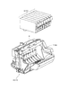
図24は、本実施形態で適用するヘッドカートリッジH1000に対し、インクタンクH1900を装着する様子を示した図である。本実施形態の記録装置は、シアン、マゼンタ、イエロー、ブラック、レッド、グリーン、およびブルーの7色のインクによって画像を形成し、従ってインクタンクH1900も7色分が独立に用意されている。そして、図に示すように、それぞれがヘッドカートリッジH1000に対して着脱自在となっている。尚、インクタンクH1900の着脱は、キャリッジM4000にヘッドカートリッジH1000が搭載された状態で行えるようになっている。 FIG. 24 is a diagram illustrating a state in which the ink tank H1900 is attached to the head cartridge H1000 applied in the present embodiment. The recording apparatus of the present embodiment forms an image with seven colors of ink of cyan, magenta, yellow, black, red, green, and blue. Therefore, the ink tank H1900 is also prepared for seven colors independently. As shown in the figure, each is detachable from the head cartridge H1000. The ink tank H1900 can be attached and detached while the head cartridge H1000 is mounted on the carriage M4000.
図25は、ヘッドカートリッジH1000の分解斜視図を示したものである。図において、ヘッドカートリッジH1000は、第1の記録素子基板H1100および第2の記録素子基板H1101、第1のプレートH1200、第2のプレートH1400、電気配線基板H1300、タンクホルダーH1500、流路形成部材H1600、フィルターH1700、シールゴムH1800などから構成されている。 FIG. 25 is an exploded perspective view of the head cartridge H1000. In the figure, a head cartridge H1000 includes a first recording element substrate H1100 and a second recording element substrate H1101, a first plate H1200, a second plate H1400, an electric wiring substrate H1300, a tank holder H1500, and a flow path forming member H1600. , Filter H1700, seal rubber H1800, and the like.
第1の記録素子基板H1100および第2の記録素子基板H1101はSi基板であり、その片面にインクを吐出するための複数の記録素子(ノズル)がフォトリソグラフィー技術により形成されている。各記録素子に電力を供給するAI等の電気配線は、成膜技術により形成されており、個々の記録素子に対応した複数のインク流路もまた、フォトリソグラフィー技術により形成されている。さらに、複数のインク流路にインクを供給するためのインク供給口が裏面に開口するように形成されている。 The first recording element substrate H1100 and the second recording element substrate H1101 are Si substrates, and a plurality of recording elements (nozzles) for ejecting ink are formed on one side thereof by a photolithography technique. Electric wiring such as AI for supplying electric power to each recording element is formed by a film forming technique, and a plurality of ink flow paths corresponding to individual recording elements are also formed by a photolithography technique. Further, an ink supply port for supplying ink to the plurality of ink flow paths is formed to open on the back surface.
図26は、第1の記録素子基板H1100および第2の記録素子基板H1101の構成を説明するための正面拡大図である。H2000〜H2600は、それぞれ異なるインク色に対応する記録素子の列(以下ノズル列ともいう)であり、第1の記録素子基板H1100には、シアンインクの供給されるノズル列H2000、マゼンタインクの供給されるノズル列H2100、およびイエローインクの供給されるノズル列H2200の3色分のノズル列が構成されている。第2の記録素子基板H1101には、ブラックインクの供給されるノズル列H2300、レッドインクの供給されるノズル列H2400、グリーンインクの供給されるノズル列H2500、およびブルーインクの供給されるノズル列H2600の4色分のノズル列が構成されている。 FIG. 26 is an enlarged front view for explaining the configuration of the first recording element substrate H1100 and the second recording element substrate H1101. H2000 to H2600 are printing element rows (hereinafter also referred to as nozzle rows) corresponding to different ink colors. The first printing element substrate H1100 has a nozzle row H2000 to which cyan ink is supplied and a supply of magenta ink. The nozzle row for two colors is configured, that is, the nozzle row H2100 to be supplied and the nozzle row H2200 to which yellow ink is supplied. The second recording element substrate H1101 includes a nozzle row H2300 to which black ink is supplied, a nozzle row H2400 to which red ink is supplied, a nozzle row H2500 to which green ink is supplied, and a nozzle row H2600 to which blue ink is supplied. No. 4 nozzle rows are configured.
各ノズル列は、記録媒体の搬送方向に1200dpi(dot/inch)の間隔で並ぶ768個のノズルによって構成され、約2ピコリットルのインク滴を吐出させる。各ノズル吐出口における開口面積は、およそ100平方μm2に設定されている。また、第1の記録素子基板H1100および第2の記録素子基板H1101は第1のプレートH1200に接着固定されており、ここには、第1の記録素子基板H1100および第2の記録素子基板H1101にインクを供給するためのインク供給口H1201が形成されている。 Each nozzle row is composed of 768 nozzles arranged at an interval of 1200 dpi (dot / inch) in the conveyance direction of the recording medium, and ejects approximately 2 picoliters of ink droplets. The opening area at each nozzle outlet is set to approximately 100 square μm 2 . The first recording element substrate H1100 and the second recording element substrate H1101 are bonded and fixed to the first plate H1200. Here, the first recording element substrate H1100 and the second recording element substrate H1101 are attached to the first recording element substrate H1100. An ink supply port H1201 for supplying ink is formed.
さらに、第1のプレートH1200には、開口部を有する第2のプレートH1400が接着固定されており、この第2のプレートH1400は、電気配線基板H1300と第1の記録素子基板H1100および第2の記録素子基板H1101とが電気的に接続されるように、電気配線基板H1300を保持している。 Further, a second plate H1400 having an opening is bonded and fixed to the first plate H1200. The second plate H1400 is composed of the electric wiring substrate H1300, the first recording element substrate H1100, and the second plate H1400. The electric wiring substrate H1300 is held so that the recording element substrate H1101 is electrically connected.
電気配線基板H1300は、第1の記録素子基板H1100および第2の記録素子基板H1101に形成されている各ノズルからインクを吐出するための電気信号を印加するものであり、第1の記録素子基板H1100および第2の記録素子基板H1101に対応する電気配線と、この電気配線端部に位置し記録装置本体からの電気信号を受け取るための外部信号入力端子H1301とを有している。外部信号入力端子H1301は、タンクホルダーH1500の背面側に位置決め固定されている。 The electrical wiring substrate H1300 applies an electrical signal for ejecting ink from each nozzle formed on the first recording element substrate H1100 and the second recording element substrate H1101, and the first recording element substrate Electrical wiring corresponding to the H1100 and the second recording element substrate H1101, and an external signal input terminal H1301 for receiving an electrical signal from the recording apparatus main body located at the end of the electrical wiring. The external signal input terminal H1301 is positioned and fixed on the back side of the tank holder H1500.
一方、インクタンクH1900を保持するタンクホルダーH1500には、流路形成部材H1600が例えば超音波溶着により固定され、インクタンクH1900から第1のプレートH1200に通じるインク流路H1501を形成している。 On the other hand, in a tank holder H1500 that holds the ink tank H1900, a flow path forming member H1600 is fixed by, for example, ultrasonic welding, and an ink flow path H1501 that communicates from the ink tank H1900 to the first plate H1200 is formed.
インクタンクH1900と係合するインク流路H1501のインクタンク側端部には、フィルターH1700が設けられており、外部からの塵埃の侵入を防止し得るようになっている。また、インクタンクH1900との係合部にはシールゴムH1800が装着され、係合部からのインクの蒸発を防止し得るようになっている。 A filter H1700 is provided at the ink tank side end of the ink flow path H1501 that engages with the ink tank H1900, and can prevent dust from entering from the outside. Further, a seal rubber H1800 is attached to the engaging portion with the ink tank H1900 so that ink can be prevented from evaporating from the engaging portion.
さらに、前述のようにタンクホルダーH1500、流路形成部材H1600、フィルターH1700及びシールゴムH1800から構成されるタンクホルダー部と、第1の記録素子基板H1100および第2の記録素子基板H1101、第1のプレートH1200、電気配線基板H1300及び第2のプレートH1400から構成される記録ヘッド部H1001とを、接着等で結合することにより、ヘッドカートリッジH1000が構成されている。 Further, as described above, the tank holder portion composed of the tank holder H1500, the flow path forming member H1600, the filter H1700, and the seal rubber H1800, the first recording element substrate H1100, the second recording element substrate H1101, and the first plate. The head cartridge H1000 is configured by bonding the recording head unit H1001 including the H1200, the electric wiring substrate H1300, and the second plate H1400 by bonding or the like.
図27は、本実施形態における画像データ変換処理の流れを説明するためのブロック図である。本実施形態で適用するインクジェット記録装置は、シアン、マゼンタ、イエロー、ブラックの基本色であるインクのほかに、レッド、グリーンおよびブルーによって記録を行うものであり、そのためにこれら7色のインクを吐出する記録ヘッドが用意されている。図27に示すように、ここに示す各処理は、記録装置とホスト装置としてのパーソナルコンピュータ(PC)によって構成されるものとする。 FIG. 27 is a block diagram for explaining the flow of image data conversion processing in the present embodiment. The ink jet recording apparatus applied in this embodiment performs recording with red, green, and blue in addition to inks that are basic colors of cyan, magenta, yellow, and black. For this purpose, these seven colors of ink are ejected. A recording head is provided. As shown in FIG. 27, each process shown here is assumed to be configured by a recording device and a personal computer (PC) as a host device.
ホスト装置のオペレーティングシステムで動作するプログラムとしてアプリケーションやプリンタドライバがあり、アプリケーションJ0001は記録装置で記録する画像データを作成する処理を実行する。実際の記録時にはアプリケーションで作成された画像データがプリンタドライバに渡される。 There are an application and a printer driver as programs that operate in the operating system of the host device, and the application J0001 executes processing for creating image data to be recorded by the recording device. At the time of actual recording, image data created by the application is passed to the printer driver.
本実施形態におけるプリンタドライバはその処理として、前段処理J0002、後段処理J0003、γ補正J0004、ハーフトーニングJ0005、および記録データ作成J0006を有するものとする。以下、プリンタドライバで行われる各処理J0002〜J0006について簡単に説明する。 Assume that the printer driver in this embodiment has a pre-stage process J0002, a post-stage process J0003, a γ correction J0004, a halftoning J0005, and a print data creation J0006 as the processes. Hereinafter, each process J0002 to J0006 performed by the printer driver will be briefly described.
(A)前段処理
前段処理J0002は色域(Gamut)のマッピングを行う。そして、sRGB規格の画像データR、G、Bによって再現される色域を、記録装置によって再現される色域内に写像するためのデータ変換を行う。具体的にはR、G、Bのそれぞれが8bitで表現されたデータを3次元のLUT(ルックアップテーブル)を用いることにより、異なる内容のR、G、Bの8bitのデータに変換する。
(A) Pre-processing The pre-processing J0002 performs color gamut mapping. Then, data conversion is performed to map the color gamut reproduced by the image data R, G, B of the sRGB standard into the color gamut reproduced by the recording apparatus. Specifically, data in which R, G, and B are each expressed in 8 bits is converted into 8-bit data of R, G, and B having different contents by using a three-dimensional LUT (lookup table).
(B)後段処理
後段処理J0003は、上記色域のマッピングがなされたデータR、G、Bに基づき、このデータが表す色を再現するインクの組み合わせに対応した色分解データY、M、C、K、R、GおよびBを求める処理を行う。ここでは前段処理と同様に、3次元LUTにて補間演算を併用して行うものとする。
(B) Subsequent Process The post-process J0003 is based on the data R, G, and B on which the color gamut is mapped, and the color separation data Y, M, C, corresponding to the combination of inks that reproduce the color represented by this data. Processing for obtaining K, R, G and B is performed. Here, similarly to the pre-processing, it is assumed that interpolation calculation is performed in combination with a three-dimensional LUT.
(C)γ処理
γ補正J0004は、後段処理J0003によって求められた色分解データの各色のデータごとにその階調値変換を行う。具体的には、記録装置の各色インクの階調特性に応じた1次元LUTを用いることにより、上記色分解データが記録装置の階調特性に線形的に対応づけられるような変換を行う。
(C) γ Processing The γ correction J0004 performs gradation value conversion for each color data of the color separation data obtained by the subsequent processing J0003. Specifically, by using a one-dimensional LUT corresponding to the gradation characteristics of each color ink of the recording apparatus, conversion is performed so that the color separation data is linearly associated with the gradation characteristics of the recording apparatus.
(D)ハーフトーニング
ハーフトーニングJ0005は、8ビットの色分解データY、M、C、K、R、GおよびBそれぞれについて4ビットのデータに変換する量子化を行う。本実施形態では、誤差拡散法を用いて256階調の8ビットデータを、9階調の4ビットデータに変換する。この4ビットデータは、記録装置におけるドット配置のパターン化処理における配置パターンを示すためのインデックスとなるデータである。
(D) Halftoning Halftoning J0005 performs quantization that converts 8-bit color separation data Y, M, C, K, R, G, and B into 4-bit data. In the present embodiment, 256-bit 8-bit data is converted to 9-gradation 4-bit data using an error diffusion method. This 4-bit data is data serving as an index for indicating an arrangement pattern in the dot arrangement patterning process in the printing apparatus.
(E)記録データの作成処理
プリンタドライバで行う処理の最後には、記録データ作成処理J0006によって、上記4ビットのインデックスデータを内容とする記録イメージデータに記録制御情報を加えた記録データを作成する。記録制御情報は、「記録媒体情報」や「記録品位情報」、「余白無し記録指定情報」等から構成されている。記録媒体情報には、記録の対象となる記録媒体の種類が記述されており、普通紙、光沢紙、はがき、プリンタブルディスクなどのうち、いずれか1種類の記録媒体が規定されている。また、記録品位情報には、記録の品位が記述されており、「高品位」、「ふつう」、「高速」等のうち、いずれか1種の品位が規定されている。記録品位情報が「高品位」を示す場合には、記録装置で高品位記録モードが実行され、記録品位情報が「高速」を示す場合には、記録装置で高速記録モードが実行される。なお、これらの記録制御情報は、ホスト装置のモニタおけるUI画面にてユーザが指定した内容に基づいて形成されるものである。また、記録イメージデータは、前述のハーフトーン処理J0005によって生成された画像データが記述さているものとする。以上のようにして生成された記録データは、記録装置へ供給される。
(E) Recording Data Creation Processing At the end of the processing performed by the printer driver, recording data creation processing J0006 creates recording data obtained by adding recording control information to the recording image data containing the 4-bit index data. . The recording control information includes “recording medium information”, “recording quality information”, “marginless recording designation information”, and the like. The recording medium information describes the type of recording medium to be recorded, and any one type of recording medium is defined among plain paper, glossy paper, postcard, and printable disc. In addition, the recording quality information describes the quality of the recording, and any one of “high quality”, “normal”, “high speed”, etc. is defined. When the recording quality information indicates “high quality”, the recording device executes a high quality recording mode, and when the recording quality information indicates “high speed”, the recording device executes a high speed recording mode. The recording control information is formed based on the content specified by the user on the UI screen on the monitor of the host device. Further, it is assumed that the recorded image data describes the image data generated by the above-described halftone process J0005. The recording data generated as described above is supplied to the recording apparatus.
記録装置は、入力されてきた上記記録データに対し、ドット配置パターン化処理J0007およびマスクデータ変換処理J0008を行う。 The recording apparatus performs dot arrangement patterning processing J0007 and mask data conversion processing J0008 on the input recording data.
(F)ドット配置パターン化処理
次に、ドット配置パターン化処理J0007について説明する。上述したハーフトーン処理では、256値の多値濃度情報(8ビットデータ)を9値の階調値情報(4ビットデータ)までにレベル数を下げている。しかし、実際に本実施形態のインクジェット記録装置が記録できる情報は、インクを記録するか否かの2値情報である。ドット配置パターン化処理では、0〜8の多値レベルをドットの有無を決定する2値レベルまで低減する役割を果たす。具体的には、このドット配置パターン化処理J0007では、ハーフトーン処理部からの出力値であるレベル0〜8の4ビットデータで表現される画素ごとに、その画素の階調値(レベル0〜8)に対応したドット配置パターンを割当て、これにより1画素内の複数のエリア各々にドットのオン・オフを定義し、1画素内の各エリアに「1」または「0」の1ビットの吐出データを配置する。
(F) Dot Placement Patterning Process Next, the dot placement patterning process J0007 will be described. In the halftone process described above, the number of levels is reduced from 256-level multi-value density information (8-bit data) to 9-level tone value information (4-bit data). However, information that can be actually recorded by the ink jet recording apparatus of the present embodiment is binary information indicating whether or not to record ink. In the dot arrangement patterning process, it plays a role of reducing the multi-value level of 0 to 8 to a binary level that determines the presence or absence of dots. Specifically, in this dot arrangement patterning process J0007, for each pixel represented by 4-bit data of
図28は、本実施形態の高画質モードにおけるドット配置パターン化処理で変換する、入力レベル0〜8に対する出力パターンを示している。図の左に示した各レベル値は、ハーフトーン処理部からの出力値であるレベル0〜レベル8に相当している。右側に配列した縦2エリア×横4エリアで構成される領域は、ハーフトーン処理で出力された1画素(ピクセル)の領域に対応するもので、縦横ともに600ppi(ピクセル/インチ)の画素密度に対応する大きさとなっている。また、1画素内の各エリアは、ドットのオン・オフが定義される最小単位に相当するもので、縦が1200dpi(ドット/インチ)、横が2400dpiの記録密度に対応するものである。本実施形態の記録装置では、上記記録密度に対応した、縦が約20μm、横が約10μmで表現される1つのエリアに対し、2plのインク滴が1つ記録されて所望の濃度が得られる様に設計されている。
FIG. 28 shows output patterns for
また、図28において、縦方向は記録ヘッドの吐出口が配列する方向であり、エリアの配列密度と吐出口の配列密度とが1200dpiという値で一致している。横方向は記録ヘッドの走査方向を示しており、本実施形態の高画質写真モードでは、記録ヘッドは2400dpiの密度で記録を行う構成となっている。 In FIG. 28, the vertical direction is the direction in which the ejection openings of the recording head are arranged, and the arrangement density of the areas and the arrangement density of the ejection openings coincide with each other at a value of 1200 dpi. The horizontal direction indicates the scanning direction of the recording head, and in the high-quality photo mode of this embodiment, the recording head is configured to perform recording at a density of 2400 dpi.
更に、図28において、丸印を記入したエリアがドットの記録を行うエリアを示しており、レベル数が上がるに従って、記録するドット数も1つずつ増加している。 Further, in FIG. 28, an area in which a circle is entered indicates an area where dots are recorded. As the number of levels increases, the number of dots to be recorded increases by one.
(4n)〜(4n+3)は、nに1以上の整数を代入することにより、入力画像の左端からの横方向の画素位置を示している。また、その下に示した各パターンは、同一の入力レベルにおいても画素位置に応じて互いに異なる複数のパターンが用意されていることを示している。すなわち、同一のレベルが入力された場合にも、記録媒体上では(4n)〜(4n+3)に示した4種類のドット配置パターンが巡回されて割当てられる構成となっているのである。そして、このような構成にしておくことは、ドット配置パターンの上段に位置するノズルと下段に位置するノズルとで吐出回数を分散させたり、記録装置特有の様々なノイズを分散させたりする効果が得られるのである。 (4n) to (4n + 3) indicate pixel positions in the horizontal direction from the left end of the input image by substituting an integer of 1 or more for n. Each of the patterns shown below indicates that a plurality of different patterns are prepared according to the pixel position even at the same input level. That is, even when the same level is input, four types of dot arrangement patterns shown in (4n) to (4n + 3) are cyclically assigned on the recording medium. Such a configuration has the effect of distributing the number of ejections between the nozzles located in the upper stage and the nozzles located in the lower stage of the dot arrangement pattern, and dispersing various noises peculiar to the printing apparatus. It is obtained.
本実施形態においては、最終的にこのような形でオリジナル画像の濃度情報が反映され、ドット配列パターン化処理を終了した段階で、記録媒体に対するドットの配列パターンが全て決定される。 In the present embodiment, the density information of the original image is finally reflected in such a form, and when the dot arrangement patterning process is completed, all the dot arrangement patterns for the recording medium are determined.
(G)マスクデータ変換処理
上述したドット配置パターン化処理により、記録媒体上の各エリアに対するドットの有無は決定されたので、この情報をそのまま記録ヘッドの駆動回路J0009に入力すれば、所望の画像を記録することは可能である。この場合、記録媒体上の同一の走査領域に対する記録を1回の走査によって完成させる、いわゆる1パス記録が実行される。しかし、しかし、ここでは、記録媒体上の同一の走査領域に対する記録を複数回の走査によって完成させる、いわゆるマルチパス記録の例をとって説明する。
(G) Mask data conversion process Since the dot arrangement patterning process described above determines the presence / absence of dots for each area on the recording medium, if this information is directly input to the driving circuit J0009 of the recording head, a desired image is obtained. It is possible to record. In this case, so-called one-pass printing is executed, in which printing for the same scanning area on the printing medium is completed by one scan. However, here, a description will be given of an example of so-called multi-pass printing in which printing on the same scanning area on the printing medium is completed by scanning a plurality of times.
図4は、マルチパス記録方法を説明するために、記録ヘッドおよび記録パターンを模式的に示したものである。P0001は記録ヘッドを示し、ここでは簡単のため16個の記録素子(ノズル)を有するものとする。ノズルは、図のように第1〜第4の4つのノズル群に分割され、各ノズル群には4つずつのノズルが含まれている。マスクパターンP0002は第1〜第4のマスクパターンP0002(a)〜P0002(d)で構成される。第1〜第4のマスクパターンP0002(a)〜P0002(d)は、それぞれ、第1〜第4のノズル群が記録可能なエリアを定義している。マスクパターンにおける黒塗りエリアは記録許容エリアを示し、白塗りエリアは非記録エリアを示している。第1〜第4のマスクパターンP0002(a)〜P0002(d)はは互いに補完の関係にあり、これらを重ね合わせると4×4のエリアに対応した領域の記録が完成される構成となっている。 FIG. 4 schematically shows a recording head and a recording pattern in order to explain the multipass recording method. P0001 denotes a recording head. Here, for simplicity, it is assumed that it has 16 recording elements (nozzles). As shown in the drawing, the nozzles are divided into first to fourth nozzle groups, and each nozzle group includes four nozzles. The mask pattern P0002 is composed of first to fourth mask patterns P0002 (a) to P0002 (d). The first to fourth mask patterns P0002 (a) to P0002 (d) define areas where the first to fourth nozzle groups can be recorded. The black area in the mask pattern indicates a recording allowable area, and the white area indicates a non-recording area. The first to fourth mask patterns P0002 (a) to P0002 (d) are complementary to each other, and when these are superimposed, recording of a region corresponding to a 4 × 4 area is completed. Yes.
P0003〜P0006で示した各パターンは、記録走査を重ねていくことによって画像が完成されていく様子を示したものである。各記録走査が終了するたびに、記録媒体は図の矢印の方向にノズル群の幅分ずつ搬送される。よって、記録媒体の同一領域(各ノズル群の幅に対応する領域)は4回の記録走査によって初めて画像が完成される構成となっている。 Each pattern indicated by P0003 to P0006 shows a state in which an image is completed by overlapping recording scans. When each recording scan is completed, the recording medium is conveyed by the width of the nozzle group in the direction of the arrow in the figure. Therefore, the same area of the recording medium (area corresponding to the width of each nozzle group) is configured such that an image is completed only after four recording scans.
以上のように、記録媒体の各領域が複数回の走査で複数のノズル群によって形成されることは、ノズル特有のばらつきや記録媒体の搬送精度のばらつき等を低減させる効果がある。また、マスクパターンの配列に工夫を施すことによって、他の様々な画像問題や記録装置の信頼性の問題などに対しても、対応策をとることが可能となる。 As described above, the formation of each region of the recording medium by a plurality of nozzle groups by a plurality of scans has an effect of reducing variations peculiar to nozzles, variations in conveyance accuracy of the recording medium, and the like. Further, by devising the arrangement of the mask pattern, it is possible to take countermeasures against other various image problems and reliability problems of the printing apparatus.
例えば、近年のように、多数の小液滴を高周波数で吐出するようなインクジェット記録ヘッドにおいては、記録ヘッドの端部に位置するノズルの吐出方向が内斜してしまう傾向がある。この場合、ノズル列の端部に位置するノズルによって形成されるドットは、正規の位置からずれた内側の位置に着弾するので、記録ヘッドの記録幅のピッチで、白スジ(以下、「端スジ」と称する)が生じてしまうことが確認されている。この様な状況であっても、上述したマスクパターンの配列を工夫することによって、端スジを目立たなくすることが出来る(例えば特開2002−096455号公報参照)。 For example, in recent years, in an ink jet recording head that ejects a large number of small droplets at a high frequency, the ejection direction of nozzles located at the end of the recording head tends to incline. In this case, since the dots formed by the nozzles located at the end of the nozzle row land at the inner position shifted from the normal position, the white stripes (hereinafter referred to as “end stripes”) are printed at the pitch of the recording width of the recording head. It is confirmed that this will occur. Even in such a situation, the edge streaks can be made inconspicuous by devising the arrangement of the mask pattern described above (see, for example, JP-A-2002-096455).
図5は、上記端スジを低減するために採用されるマスクパターンの一例を示した図である。図5のマスクパターンの黒エリアは図4のマスクパターンの黒エリアと同じ役割を担う箇所であり、記録を許容するエリアを示す。図5のマスクパターンの白エリアは図4のマスクパターンの白エリアと同じ役割を担う箇所であり、記録を許容しないエリアを示す。ここでは768個のノズルを有する記録ヘッドを用い、4パスのマルチパス記録を実施する場合を例に示している。図4の場合と同様に、全768ノズルは4つのノズル群に分割されているが、ここではノズルの位置によってマスクパターンの記録率(マスクパターンを構成する黒エリアと白エリアの合計数に対する黒エリアの数の割合)が異なっているのがわかる。第1ノズル群に対応するマスクパターンの記録率はN%、第2ノズル群に対応するマスクパターンの記録率はM(但し、M>N)%、第3ノズル群に対応するマスクパターンの記録率はM%、第4ノズル群に対応するマスクパターンの記録率はN%となっており、これら4つのノズル群に対応したマスクパターンの記録率の合計(N+M+M+N)は100%となる。このように中央部のノズルの記録率は比較的高く設定されているが、端部に行くに従って記録率は徐々に低くなっている。 FIG. 5 is a diagram showing an example of a mask pattern employed to reduce the end stripe. The black area of the mask pattern in FIG. 5 is a portion that plays the same role as the black area of the mask pattern in FIG. 4 and indicates an area that allows recording. The white area of the mask pattern in FIG. 5 is a part that plays the same role as the white area of the mask pattern in FIG. 4 and indicates an area that does not allow recording. Here, a case where a recording head having 768 nozzles is used and 4-pass multi-pass printing is performed is shown as an example. As in the case of FIG. 4, all 768 nozzles are divided into four nozzle groups. Here, the recording rate of the mask pattern (the black number corresponding to the total number of black areas and white areas constituting the mask pattern depends on the position of the nozzles). It can be seen that the ratio of the number of areas is different. The recording rate of the mask pattern corresponding to the first nozzle group is N%, the recording rate of the mask pattern corresponding to the second nozzle group is M (where M> N)%, and the recording of the mask pattern corresponding to the third nozzle group is performed. The rate is M%, the mask pattern recording rate corresponding to the fourth nozzle group is N%, and the sum of the mask pattern recording rates corresponding to these four nozzle groups (N + M + M + N) is 100%. As described above, the recording rate of the central nozzle is set to be relatively high, but the recording rate gradually decreases toward the end.
上述した吐出方向の内斜は、より小液滴のインクが、より高速に、より高密度に記録されるほど顕著に現れることが確認されている。よって、端部ノズルの記録率を中央部ノズルに比べて低く設定することは、端部に位置するノズルの内斜傾向を和らげることが出来る。また、多少内斜傾向にあったとしても、吐出されるドットの数自体が低減されているので、着弾位置ずれによる端スジを目立たなくする効果も得られる。 It has been confirmed that the above-described inner oblique in the ejection direction appears more markedly as smaller droplets of ink are recorded at higher speed and higher density. Therefore, setting the recording rate of the end nozzles to be lower than that of the central nozzle can alleviate the inner oblique tendency of the nozzles located at the end parts. Further, even if there is a slight inclining tendency, the number of ejected dots is reduced, so that the effect of making the edge streaks due to the landing position deviation inconspicuous is also obtained.
本実施形態においては、上述の図5に示したマスクパターンが、記録装置本体内のメモリに格納されている。そして、マスクデータ変換処理J0008においては、当該マスクデータと上述したドット配置パターン化処理J0007により出力された2値データとの間でAND処理を行うことにより、各記録走査での記録対象となる2値データが決定され、その2値データが駆動回路J0009に入力される。これにより、記録ヘッドH1001が駆動されて2値データに従ってインクが吐出される。 In the present embodiment, the mask pattern shown in FIG. 5 is stored in a memory in the recording apparatus main body. In the mask data conversion process J0008, AND processing is performed between the mask data and the binary data output by the above-described dot arrangement patterning process J0007, so that 2 becomes a print target in each print scan. Value data is determined, and the binary data is input to the drive circuit J0009. As a result, the recording head H1001 is driven and ink is ejected according to the binary data.
なお、本実施形態においては、後述するように記録モードの種類(高品位記録モードと高速記録モード)と記録媒体上の記録位置(中央部あるいは端部)によって用いるマスクパターンを異ならせている。詳しくは、記録媒体の中央部に対する記録のための第1マスクパターンと記録媒体の端部(先端部あるいは後端部の少なくとも一方)に対する記録のための第2マスクパターンが記録モードそれぞれについて設けられている。従って、メモリには、高品位記録モード用の第1および第2マスクパターンと、高速記録モード用の第1および第2マスクパターンが格納されている。 In the present embodiment, as will be described later, the mask pattern used is different depending on the type of recording mode (high-quality recording mode and high-speed recording mode) and the recording position (center or end) on the recording medium. Specifically, a first mask pattern for recording on the central portion of the recording medium and a second mask pattern for recording on the end portion (at least one of the front end portion or the rear end portion) of the recording medium are provided for each recording mode. ing. Therefore, the memory stores the first and second mask patterns for the high-quality recording mode and the first and second mask patterns for the high-speed recording mode.
(記録媒体先後端部での記録)
本実施形態の記録装置は、記録媒体の端部に余白を設けずに画像の記録を行う、いわゆる「余白無し記録」を実現可能な記録装置とする。
(Recording at the front and rear end of the recording medium)
The recording apparatus of the present embodiment is a recording apparatus capable of realizing so-called “marginless recording” in which an image is recorded without providing a margin at the end of the recording medium.
図6は、本実施形態の記録装置でA4サイズの記録媒体に余白無し記録を実行する際の、先端部、中央部および後端部の領域をそれぞれ示した図である。すなわち、図1〜図3を用いて説明したように、記録媒体の先端が排紙ローラM3100に支持される以前に記録される領域を先端部、記録媒体の後端が搬送ローラM3060から外れた後に記録される領域を後端部としている。また、先端部と後端部以外の領域を中央部としており、当該中央部は搬送ローラM3060と排紙ローラM3100の両方にて記録媒体が保持された状態で記録される領域である。 FIGS. 6A and 6B are diagrams respectively showing the front end portion, the central portion, and the rear end region when marginless recording is performed on an A4 size recording medium by the recording apparatus of the present embodiment. That is, as described with reference to FIGS. 1 to 3, the recording medium has its leading end positioned before the leading end of the recording medium is supported by the paper discharge roller M3100, and the trailing end of the recording medium is separated from the conveying roller M3060. The area recorded later is the rear end. Further, an area other than the front end part and the rear end part is set as a central part, and the central part is an area where the recording medium is held by both the transport roller M3060 and the paper discharge roller M3100.
以下説明のため3種類の搬送状態を次のように定義する。すなわち、搬送ローラによって支持され、排紙ローラによって支持されない状態の搬送動作を第1搬送動作とする。また、搬送ローラおよび排紙ローラの双方によって支持される状態の搬送動作を第2搬送動作とする。更に、搬送ローラによって支持されず、排紙ローラによって支持されている状態の搬送動作を第3搬送動作とする。このように搬送動作を定義した状態でより厳密に考慮すると、マルチパス記録を実行する場合には、記録領域を次の5つの領域に分割できる。すなわち、第1搬送動作のみを介在させた複数回のパスによって画像が完成される領域A、第1搬送動作と第2搬送動作を介在させた複数回のパスによって画像が完成される領域B、第2搬送動作のみを介在させた複数回のパスによって画像が完成される領域C、第2搬送動作と第3搬送動作を介在させた複数回のパスによって画像が完成される領域D、更に第3搬送動作のみを介在させた複数回のパスによって画像が完成される領域Eである。以下に説明する実施形態においては、上記5つの領域について、領域Aと領域Bを先端部、領域Cを中央部、領域Dと領域Eを後端部とし、用意した2種類のマスクパターンを適用させている。 In the following description, three types of transport states are defined as follows. That is, a transport operation that is supported by the transport roller and not supported by the paper discharge roller is referred to as a first transport operation. Further, a transport operation in a state supported by both the transport roller and the paper discharge roller is referred to as a second transport operation. Further, a transport operation that is not supported by the transport roller but supported by the paper discharge roller is referred to as a third transport operation. Considering more strictly in a state where the transport operation is defined in this way, when performing multi-pass printing, the printing area can be divided into the following five areas. That is, a region A in which an image is completed by a plurality of passes through which only the first transport operation is interposed, a region B in which an image is completed by a plurality of passes through which the first transport operation and the second transport operation are interposed, Region C in which an image is completed by a plurality of passes with only the second transport operation interposed therein, Region D in which an image is completed by a plurality of passes with the second transport operation and the third transport operation interposed, and This is an area E where an image is completed by a plurality of passes with only three transport operations interposed. In the embodiment described below, two types of prepared mask patterns are applied to the above five regions, with region A and region B being the leading end, region C being the central portion, and region D and region E being the trailing end. I am letting.
本実施形態では、配列するノズル列のうち、より下流側(排紙ローラ側)に位置する一部分のノズルによって、先端部および後端部への記録を行っている。従って、先端部として扱われる領域よりも後端部として扱われる領域のほうが若干広くなっている。 In the present embodiment, recording is performed on the front end portion and the rear end portion by a part of the nozzles located on the downstream side (discharge roller side) in the arranged nozzle rows. Therefore, the area treated as the rear end is slightly wider than the area treated as the front end.
(マスクパターンの記録率と画像品位との関係)
以下に、発明者らが行った検討について説明する。図7は、発明者らが作成した、複数のマスクパターンの記録率をグラフとして示した図である。図7において、横軸は記録ヘッド上に配列する768本のノズルの位置を示している。また、縦軸は、それぞれのノズルに対する記録率を示している。本発明者らは、本検討を実行するためにa〜eの5種類のマスクパターンを作成した。本検討においては、4パスのマルチパス記録に適用可能なマスクパターンとしているため、曲線a〜eそれぞれの平均記録率はどれも25%となっている。ここで、平均記録率は、同一領域を完成させるのに要するパス数をKとしたとき、100/Kで表される。
(Relationship between mask pattern recording rate and image quality)
In the following, the study conducted by the inventors will be described. FIG. 7 is a graph showing the recording rates of a plurality of mask patterns created by the inventors. In FIG. 7, the horizontal axis indicates the positions of 768 nozzles arranged on the recording head. The vertical axis shows the recording rate for each nozzle. The present inventors created five types of mask patterns a to e in order to perform this study. In this examination, since the mask pattern is applicable to 4-pass multi-pass printing, the average recording rate of each of the curves a to e is 25%. Here, the average recording rate is represented by 100 / K, where K is the number of passes required to complete the same area.
なお、マスクパターンの記録率とは、マスクパターンを構成する記録許容エリア(図5の黒エリア)と非記録許容エリア(図5の白エリア)の合計数に対する記録許容エリアの数の割合を百分率で表したものである。以下、これを具体的に説明する。例えば、図5のマスクパターンの横方向(ノズル並び方向と直交する方向)の大きさが768エリア分であった場合を考える。すると、1つのノズルに対応するマスクパターンを構成する記録許容エリアと非記録許容エリアの合計数は768個となる。この768個のエリアのうち、記録許容エリアが192個、非記録許容エリアが576個であった場合、このノズルに対応するマスクパターンの記録率は25(=192/768×100)%ということになる。 The mask pattern recording rate is the percentage of the number of recording allowable areas to the total number of recording allowable areas (black areas in FIG. 5) and non-recording allowable areas (white areas in FIG. 5) constituting the mask pattern. It is represented by. This will be specifically described below. For example, consider a case where the size of the mask pattern in FIG. 5 in the horizontal direction (direction orthogonal to the nozzle arrangement direction) is 768 areas. Then, the total number of print permitting areas and non-printing permitting areas constituting the mask pattern corresponding to one nozzle is 768. Of these 768 areas, if the print allowable area is 192 and the non-print allowable area is 576, the recording rate of the mask pattern corresponding to this nozzle is 25 (= 192/768 × 100)%. become.
さて、図7のa〜eの全ての曲線において、記録率の分布は中央部が高く端部が低くなっているが、その中でも最も両者の記録率の差が小さいのが曲線aである。曲線aでは、中央部の記録率が35%、両端部の記録率が15%となっており、平均記録率25%に対する端部の記録率の割合は、15/25=0.6となっている。以後、このような平均記録率に対する端部記録率の割合を、端部記録率比と称することとする。 In all of the curves a to e in FIG. 7, the distribution of the recording rate is high in the central portion and low in the end portion. Among them, the curve a has the smallest difference between the recording rates. In curve a, the recording rate at the center is 35%, the recording rate at both ends is 15%, and the ratio of the recording rate at the end to the average recording rate of 25% is 15/25 = 0.6. ing. Hereinafter, the ratio of the edge recording rate to the average recording rate is referred to as an edge recording rate ratio.
一方、中央部と端部の記録率の差が最も大きいのが曲線eである。曲線eでは、中央部の記録率が45%、両端部の記録率が5%であり、平均記録率25%に対する端部の記録率の割合は、5/25=0.2となっている。b〜dの曲線はaとeの間を均等内分される特性を有するマスクパターンの記録率を示している。 On the other hand, the curve e is the largest in the recording rate difference between the central portion and the end portion. In curve e, the recording rate at the center is 45%, the recording rate at both ends is 5%, and the ratio of the recording rate at the end to the average recording rate of 25% is 5/25 = 0.2. . Curves b to d show the recording rate of the mask pattern having the characteristic of equally dividing between a and e.
図8は、図7で示したa〜eのマスクについて、端部の記録率、中央部の記録率および端部記録率比を示した表である。b、c、dのマスクパターンについては、それぞれ端部記録率比が0.5、0.4および0.3となっている。 FIG. 8 is a table showing the edge recording rate, the central recording rate, and the edge recording rate ratio for the masks a to e shown in FIG. For the b, c, and d mask patterns, the end recording ratios are 0.5, 0.4, and 0.3, respectively.
図9(A)は、図7のaで示したマスクパターンの例を示している。図9Aでは縦方向が768個のノズル並び方向に相当しており、中央部ノズルの記録率が35%、両側最端部ノズルの記録率が15%となっている。図9(B)は、図9(A)と同様の端部記録率比を有しながらも、256ノズルで記録する際のマスクパターンを示している。図9Bにおいても、中央部ノズルの記録率は35%、両側最端部ノズルの記録率は15%となっている。 FIG. 9A shows an example of the mask pattern shown by a in FIG. In FIG. 9A, the vertical direction corresponds to the 768 nozzle arrangement direction, the recording rate of the central nozzle is 35%, and the recording rate of both endmost nozzles is 15%. FIG. 9B shows a mask pattern for recording with 256 nozzles while having the same edge recording ratio as in FIG. 9A. Also in FIG. 9B, the recording rate of the central nozzle is 35%, and the recording rate of the nozzles on both ends is 15%.
図10(A)は、図7のdで示したマスクパターンの例を示している。図10Aでは縦方向が768個のノズル並び方向に相当しており、中央部ノズルの記録率が42.5%、両側最端部ノズルの記録率が7.5%となっている。図10(B)は、図9(A)と同様の端部記録率比を有しながらも、256ノズルで記録する際のマスクパターンを示している。図10Bにおいても、中央部ノズルの記録率は42.5%、両側最端部ノズルの記録率は7.5%となっている。図10(A)および(B)ともに、図9(A)および(B)で示したマスクパターンよりも、中央部の記録率が高く、両端部の記録率が低くなっていることが確認できる。 FIG. 10A shows an example of the mask pattern shown by d in FIG. In FIG. 10A, the vertical direction corresponds to the direction in which 768 nozzles are arranged, the recording rate of the central nozzle is 42.5%, and the recording rate of the nozzles on both ends is 7.5%. FIG. 10B shows a mask pattern for recording with 256 nozzles while having the same edge recording ratio as in FIG. 9A. Also in FIG. 10B, the recording rate of the central nozzle is 42.5%, and the recording rate of both endmost nozzles is 7.5%. In both FIGS. 10A and 10B, it can be confirmed that the recording rate at the center is higher and the recording rate at both ends is lower than the mask pattern shown in FIGS. .
本発明者らは、先端部および後端部での記録状態を再現するために、図9(B)や図10(B)で示したような、256ノズル用のマスクパターンを用いて、搬送量のばらつきに対する画像の乱れを確認した。以下に、具体的な検討方法を説明する。 In order to reproduce the recording state at the front end portion and the rear end portion, the present inventors use a mask pattern for 256 nozzles as shown in FIG. 9B or FIG. The disturbance of the image with respect to the variation in the amount was confirmed. A specific examination method will be described below.
本実施形態の記録装置においては、記録ヘッド上の各ノズルは1200dpiで配列している。よって、連続する256ノズルを用いて4パスのマルチパス記録を行う場合、各記録走査間で行われるべき搬送量は、
25.4(mm/inch)/1200×256/4≒1.3547(mm)
となる。この値に対して、1μmずつ搬送量を前後に変化させながら、上記マスクパターンを用いて、グレーやその他の色相における一様性の高い複数種類のパターンを記録した。その後、出力された画像を目視で観察することにより、搬送量が小さすぎる場合に発生する黒スジや、搬送量が大きすぎる場合に発生する白スジの目立ち方にについて、評価を行った。
In the recording apparatus of the present embodiment, the nozzles on the recording head are arranged at 1200 dpi. Therefore, when performing 4-pass multi-pass printing using 256 continuous nozzles, the transport amount to be performed between each print scan is
25.4 (mm / inch) /1200×256/4≈1.3547 (mm)
It becomes. With respect to this value, a plurality of types of patterns with high uniformity in gray and other hues were recorded using the mask pattern while changing the carry amount forward and backward by 1 μm. Thereafter, by visually observing the output image, evaluation was made on how to notice black streaks that occur when the transport amount is too small and white stripes that occur when the transport amount is too large.
図11は、上記目視での評価結果を説明するための図である。図11において、横軸はマスクパターンの端部記録率比を示している。また、縦軸は、正規の搬送量に対する搬送誤差(ずれ量)を示している。5つの矢印は、作成した5種類のマスクパターンa〜eに対応し、それぞれ、許容できる搬送誤差量の範囲を矢印で示している。図によれば、端部記録率比が0.6であるaのマスクパターンでは、正規の搬送量に対し±3μm程度の誤差しか許容できないのに対し、端部記録率比が0.3であるdのマスクパターンでは、−4〜+12μm程度の誤差が許容出来ていることが確認できる。なお、端部記録率比が0.2であるeのマスクパターンについては、検討を行った誤差範囲全体にわたって、白スジや黒スジが目立つことは無かったので、ここでは破線の矢印で確認された領域を示している。 FIG. 11 is a diagram for explaining the visual evaluation results. In FIG. 11, the horizontal axis indicates the edge pattern recording ratio of the mask pattern. The vertical axis indicates the transport error (deviation amount) with respect to the regular transport amount. The five arrows correspond to the five types of created mask patterns a to e, and each indicates an allowable conveyance error range by arrows. According to the figure, in the mask pattern a with an end recording rate ratio of 0.6, only an error of about ± 3 μm is allowed with respect to the normal transport amount, whereas the end recording rate ratio is 0.3. It can be confirmed that an error of about −4 to +12 μm is allowed in a certain mask pattern d. For the mask pattern of e with an end portion recording rate ratio of 0.2, white stripes and black stripes did not stand out over the entire error range studied, so here they are confirmed by broken arrows. Shows the area.
以上の結果より、評価を行ったマスクパターンのうち、より左側にあるもの、すなわち、端部記録率比が小さいマスクパターンほど、白スジ、黒スジが目立ちにくいことが分かる。搬送量のばらつきに起因する白スジや黒スジは、記録ヘッドの各記録走査間のつなぎ部分、すなわち記録領域の端部に現れるものである。よって、最も弊害の現れやすい領域の記録率を下げて、黒スジや白スジの存在を希薄な状態にしておきながら、別の記録走査でこの部分をカバーするノズル群の記録率を高く設定することにより、つなぎ部における白スジや黒スジを目立ちにくくすることが出来るのだと推測される。以下に、端部記録率比(マスクパターンの勾配)と画像弊害との関係を本発明者らが検証した結果を説明する。 From the above results, it can be seen that white stripes and black stripes are less conspicuous as the mask pattern on the left side of the evaluated mask patterns, that is, the mask pattern with a smaller edge recording rate ratio. White stripes and black stripes resulting from the variation in the carry amount appear at the connection between the print scans of the print head, that is, at the end of the print area. Therefore, the recording rate of the nozzle group that covers this portion is set high by another recording scan while lowering the recording rate of the area where the most harmful effect appears and keeping the presence of black and white stripes in a sparse state. Thus, it is presumed that white stripes and black stripes at the connecting portion can be made inconspicuous. Hereinafter, the results of verification by the present inventors on the relationship between the edge recording rate ratio (mask pattern gradient) and image defects will be described.
図29(A)〜(C)および図30(A)〜(C)は、端部記録率比が画像品位に及ぼす影響を説明するための図である。各図において、横軸は搬送方向に対する記録媒体上の位置を1画素単位で示している。縦軸は、各位置に対するマスクパターンの記録率を示している。本例は、4パスのマルチパス記録を実行した場合を示しており、各位置は実線や破線で示した複数のマスクパターンによって記録が行われている。また、グラフの上部に示された太い実線は、各位置における画像濃度を示し、矢印で示した箇所は、記録素子列の端部で記録される位置、すなわち記録走査のつなぎ部となる位置を示している。 FIGS. 29A to 29C and FIGS. 30A to 30C are views for explaining the influence of the edge recording rate ratio on the image quality. In each figure, the horizontal axis indicates the position on the recording medium in the conveyance direction in units of one pixel. The vertical axis represents the mask pattern recording rate for each position. This example shows a case where 4-pass multi-pass printing is performed, and printing is performed at each position by a plurality of mask patterns indicated by solid lines or broken lines. Also, the thick solid line shown at the top of the graph indicates the image density at each position, and the position indicated by the arrow indicates the position recorded at the end of the recording element array, that is, the position that becomes the connecting part of the recording scan. Show.
図30(A)〜(C)は、グラデーションの勾配が比較的小さい、即ち、端部記録率比が大きい4パス用のマスクパターンを用い、記録媒体の搬送量を正規の量よりも短くあるいは長いくした場合の黒すじや白すじの発生状態を示している。図30(A)は搬送量が正規の量であった場合を示している。この場合、搬送量が正規量であるので、画像上には黒すじも白スジも現れていない。これに対し、図30(B)は搬送量が正規よりも短い量であった場合を示している。この場合、矢印で示したつなぎ部には、他の領域よりも濃度の高い部分、すなわち黒すじが確認される。更に、図30(C)は搬送量が正規よりも長い量であった場合を示している。この場合、矢印で示したつなぎ部には、他の領域よりも濃度の低い部分、すなわち白すじが確認される。 30A to 30C use a 4-pass mask pattern having a relatively small gradation gradient, that is, a large end recording rate ratio, and the recording medium conveyance amount is shorter than the normal amount or It shows the occurrence of black lines and white lines when the line lengthens. FIG. 30A shows a case where the transport amount is a regular amount. In this case, since the transport amount is a normal amount, neither black streaks nor white streaks appear on the image. On the other hand, FIG. 30B shows a case where the transport amount is shorter than the normal amount. In this case, a portion having a higher density than other regions, that is, a black streak is confirmed at the connecting portion indicated by the arrow. Further, FIG. 30C shows a case where the transport amount is longer than the normal amount. In this case, a portion having a lower density than other regions, that is, a white streak is confirmed at the connecting portion indicated by the arrow.
一方、図29(A)〜(C)は、グラデーションの勾配が比較的大きい、即ち、端部記録率比が小さい4パス用のマスクパターンを用いた場合の黒すじや白すじの発生状態を示している。図29(A)は搬送量が正規の量であった場合を示している。この場合、図30(A)と同様に、画像上には黒すじも白すじも現れていない。これに対し、図29(B)は搬送量が正規よりも短い量であった場合を示している。この場合、図30(B)と同様の理由から黒すじが確認されるが、図30(B)よりも黒すじは軽減されている。更に、図29(C)は搬送量が正規よりも長い量であった場合を示しているが、この場合においても、図30(C)よりも、白すじが軽減されている。 On the other hand, FIGS. 29A to 29C show the occurrence of black lines and white lines when a 4-pass mask pattern having a relatively large gradation gradient, that is, a small edge recording ratio, is used. Show. FIG. 29A shows a case where the transport amount is a regular amount. In this case, as in FIG. 30A, neither black streaks nor white streaks appear on the image. On the other hand, FIG. 29B shows a case where the transport amount is shorter than the normal amount. In this case, black streaks are confirmed for the same reason as in FIG. 30B, but the black streaks are reduced as compared with FIG. Further, FIG. 29C shows a case where the carry amount is longer than the normal amount, but even in this case, white streaks are reduced as compared with FIG. 30C.
以上の検討結果によれば、端部記録率比が小さいマスクパターンほど、搬送誤差によって生じる黒すじや白すじが目立ちにくいことが分かる。但し、その一方で、実際に観察を行った画像においては、端部記録率比が小さいマスクパターンほど、1回の記録走査での記録領域の中央部のマスクパターン記録率が高い部分に濃度の高い部分が現れることが確認された。より詳しく説明すると、このバンド状の濃度ムラは、端部記録率比の大きいaのマスクパターンでは確認されなかったものの、bのマスクパターンでは僅かに存在が確認される程度となり、c、d、eと端部記録率比が小さくなるにつれて、よりはっきりと認識される傾向にあった。 From the above examination results, it can be seen that a black pattern and a white streak caused by a transport error are less conspicuous as the end portion recording rate ratio is smaller. However, on the other hand, in the actually observed image, the mask pattern with a smaller edge recording rate ratio has a higher density in the portion where the mask pattern recording rate at the center of the recording area in one recording scan is higher. It was confirmed that a high part appeared. More specifically, although the band-shaped density unevenness was not confirmed in the mask pattern a with a large end portion recording ratio, it was only slightly confirmed in the mask pattern b, and c, d, As the ratio of e to the edge recording rate decreased, the tendency was more clearly recognized.
明確なメカニズムは断定できないが、一連のノズル列の中で、記録率の偏りがあまりにも激しいと、温度分布や吐出頻度の差から吐出性能に差が生じることも確認されている。また、記録走査で記録媒体に打ち込むインク滴の密度により、記録媒体上でインク滴が記録媒体に浸透・定着する前につながる頻度が異なることも考えられる。それが前記濃度の濃い部分が現れる原因となっている可能性もある。 Although a clear mechanism cannot be determined, it has also been confirmed that if the recording rate deviation is too severe in a series of nozzle rows, there will be a difference in ejection performance due to differences in temperature distribution and ejection frequency. It is also conceivable that the frequency at which ink droplets are connected to the recording medium before penetrating and fixing on the recording medium varies depending on the density of the ink droplets that are ejected onto the recording medium in the recording scan. This may be the cause of the appearance of the dark portion.
また、特開2002−096455号公報に開示されているような本来のグラデーションマスクにおいては、記録率の分布を滑らかな曲線に保っておくことで、端部ヨレを防止し、端スジを目立たなくする効果が得られる。しかし、eのマスクパターンのように記録率の変動があまりに激しいと、その十分な効果が得られない懸念も生じてくる。更にまた、インクジェット記録ヘッドの複数のノズルにおいては、記録率を出来るだけ一様にしておく方が、寿命の観点からも好ましいと言える。 Further, in the original gradation mask as disclosed in Japanese Patent Application Laid-Open No. 2002-096455, the distribution of the recording rate is kept in a smooth curve, thereby preventing the edge deviation and making the edge stripe inconspicuous. Effect is obtained. However, if the recording rate fluctuates too much like the mask pattern e, there is a concern that the sufficient effect cannot be obtained. Furthermore, it can be said that it is preferable from the viewpoint of life to keep the recording rate as uniform as possible in the plurality of nozzles of the ink jet recording head.
以上の検討結果から、本発明者は、次のような知見を得た。すなわち、搬送誤差に伴って生じる白スジや黒スジを低減するには、端部記録率比の小さいマスクパターン(勾配が大きいマスクパターン)を用いることが有利である。その一方で、白スジや黒スジがあまり目立たない場合には、端部記録率比の大きいマスクパターン(勾配が小さいマスクパターン)を用いることが有利である。 From the above examination results, the present inventor has obtained the following knowledge. That is, it is advantageous to use a mask pattern having a small edge recording rate ratio (a mask pattern having a large gradient) in order to reduce white stripes and black stripes caused by a conveyance error. On the other hand, when white stripes and black stripes are not so conspicuous, it is advantageous to use a mask pattern having a large edge recording ratio (mask pattern having a small gradient).
(記録モードの構成)
以上の検討結果を踏まえ、記録速度を重視して画像を出力する高速記録モード、および画像品位を重視して画像を出力する高品位記録モードの2つの記録モードにて、余白無し記録を実現する場合について説明する。なお、後述から明らかなように、高品位記録モードは、中央部記録時に使用するノズル数(768個)に比べて先後端部記録時に使用するノズル数(64個)を低減させており、その低減の割合((768−64)/768=11/12)を比較的大きくし、1回の走査における記録幅を比較的小さくすることで、高品位印字を実現している。一方、高速記録モードでは、中央部記録時に使用するノズル数(768個)に比べて先後端部記録時に使用するノズル数(256個)を低減させているが、その低減の割合((768−256)/768=2/3)を比較的小さく、1回の走査における記録幅を比較的大きくすることで、高速印字を実現している。
(Recording mode configuration)
Based on the results of the above studies, marginless recording is realized in two recording modes: a high-speed recording mode that outputs images with an emphasis on recording speed, and a high-quality recording mode that outputs images with an emphasis on image quality. The case will be described. As will be apparent from the description below, the high-quality recording mode reduces the number of nozzles (64) used for leading and trailing edge recording compared to the number of nozzles (768) used for central recording. The reduction ratio ((768−64) / 768 = 11/12) is relatively large, and the recording width in one scan is relatively small, thereby realizing high-quality printing. On the other hand, in the high-speed recording mode, the number of nozzles (256) used at the front and rear end recording is reduced as compared with the number of nozzles (768) used at the center recording, but the reduction ratio ((768- 256) / 768 = 2/3) is relatively small, and the recording width in one scan is relatively large, thereby realizing high-speed printing.
図12(A)は、本実施形態の高速記録モードにおいて、記録媒体の中央部で適用するマスクパターンの記録率分布を示した図である。ここでは、4パスのマルチパス記録を実行するものとし、図7の曲線aで示したマスクパターンが適用されている。すなわち、全ノズル数768のうち、最端部のノズルの記録率は15%、中央部のノズルの記録率は35%、更に端部記録率比は0.6となっている。 FIG. 12A is a diagram showing the recording rate distribution of the mask pattern applied at the center of the recording medium in the high-speed recording mode of the present embodiment. Here, it is assumed that 4-pass multi-pass printing is executed, and the mask pattern shown by the curve a in FIG. 7 is applied. That is, out of the total number of nozzles 768, the recording rate of the nozzle at the end is 15%, the recording rate of the nozzle at the center is 35%, and the end recording rate ratio is 0.6.
図12(B)は、上記記録率および端部記録率比を図12(A)と同値に保ったまま、記録に用いるノズル数を128まで制限した状態のマスクパターンを示している。従来、一般的に適用されてきた先後端部領域におけるマスクパターンは、このように中央部で適用されるマスクパターンと同等の端部記録率比を有するものであった。 FIG. 12B shows a mask pattern in a state where the number of nozzles used for recording is limited to 128 while the recording rate and the edge recording rate ratio are kept at the same values as those in FIG. Conventionally, the mask pattern in the front / rear end region, which has been generally applied, has an end portion recording rate ratio equivalent to the mask pattern applied in the center portion.
図12(C)は、本実施形態において、高速記録モードの先後端部領域で適用するマスクパターンを示している。ここでは、使用するノズル数を従来の2倍の256とし、図7において曲線dとして示したものと同等の記録率を有するマスクパターンを適用している。すなわち、中央部のノズルの記録率は42.5%、最端部のノズルの記録率は7.5%、端部記録率比は0.3となっている。 FIG. 12C shows a mask pattern applied in the front and rear end regions in the high-speed recording mode in this embodiment. Here, the number of nozzles to be used is 256, which is twice that of the prior art, and a mask pattern having a recording rate equivalent to that shown as curve d in FIG. 7 is applied. That is, the recording rate of the central nozzle is 42.5%, the recording rate of the outermost nozzle is 7.5%, and the end recording rate ratio is 0.3.
再度、図11を参照するに、搬送誤差については、端部記録率比が小さい程、その許容範囲が広くなっている。端部記録率比が0.6である曲線aに対し、端部記録率比が0.3である曲線dは、搬送誤差の許容範囲が2倍以上にも増大している。よって、記録幅すなわち記録に用いるノズル数を図12(B)の2倍に設定し、それに伴い搬送量も2倍に設定し、記録時間を1/2に短縮しても、画像品位は従来の状態を維持すること出来るのである。 Referring to FIG. 11 again, the allowable range of the transport error is wider as the end recording rate ratio is smaller. In contrast to the curve a having an end recording rate ratio of 0.6, the curve d having an end recording rate ratio of 0.3 has an allowable range of conveyance error increased by more than twice. Therefore, even if the recording width, that is, the number of nozzles used for recording is set to double that in FIG. This state can be maintained.
図13(A)は、本実施形態の高品位記録モードにおいて、記録媒体の中央部で適用するマスクパターンの記録率分布を示した図である。ここでは、より画像品位を高めるために、8パスのマルチパス記録を実行する。全ノズル数768のうち、最端部のノズルの記録率は7.5%、中央部のノズルの記録率は17.5%となり、高速記録モードに比べて全体的に記録率が半減されている。ただし、端部記録率比は高速記録モード同等の0.6となっている。 FIG. 13A is a diagram showing the recording rate distribution of the mask pattern applied at the center of the recording medium in the high quality recording mode of the present embodiment. Here, in order to further improve the image quality, 8-pass multi-pass printing is executed. Out of the total number of nozzles 768, the recording rate of the nozzle at the end is 7.5% and the recording rate of the nozzle at the center is 17.5%, and the overall recording rate is halved compared to the high-speed recording mode. Yes. However, the end portion recording rate ratio is 0.6, which is equivalent to the high-speed recording mode.
図13(B)は、本実施形態との比較例として、上記記録率および端部記録率比を図13(A)と同値に保ったまま、記録に用いるノズル数を128まで制限した状態のマスクパターンを示している。 FIG. 13B shows, as a comparative example with the present embodiment, a state in which the number of nozzles used for recording is limited to 128 while maintaining the recording rate and the edge recording rate ratio at the same values as in FIG. A mask pattern is shown.
図13(C)は、本実施形態において、高品位記録モードの先後端部領域で適用するマスクパターンを示している。ここでは、使用するノズル数を図13(B)の1/2の64としている。但し、中央部および最端部のノズルの記録率は、夫々、図13(B)と同等の17.5%および7.5%としており、端部記録率比も0.6となっている。先にも説明したが、先端部および後端部における画像品位の乱れは、搬送量のばらつきによるもののみではない。紙間距離が不安定になることも、画像品位を劣化させる原因の1つである。本実施形態の高品位モードでは、この紙間距離の変動の影響も極力抑えるために、あえて使用するノズル数を低減した。以下に、この効果を具体的に説明する。 FIG. 13C shows a mask pattern applied in the front and rear end regions in the high quality recording mode in the present embodiment. Here, the number of nozzles to be used is 64, which is 1/2 of FIG. However, the recording ratios of the nozzles at the center and the outermost end are 17.5% and 7.5%, respectively, which are equivalent to FIG. 13B, and the end recording ratio is 0.6. . As described above, the disturbance in image quality at the leading end and the trailing end is not only due to variations in the transport amount. Instability in the inter-paper distance is also one of the causes of image quality degradation. In the high quality mode of the present embodiment, the number of nozzles used is intentionally reduced in order to suppress the influence of the variation in the inter-paper distance as much as possible. This effect will be specifically described below.
図14(A)および(B)は、本実施形態の高速記録モードと高品位記録モードにおける、記録に用いるノズル領域(使用ノズル数)と紙間距離の様子を説明するための模式図である。 FIGS. 14A and 14B are schematic diagrams for explaining the state of the nozzle area (number of used nozzles) and the inter-paper distance used for recording in the high-speed recording mode and the high-quality recording mode of the present embodiment. .
図14(A)および(B)において、H1000は記録ヘッドであり、202は、記録ヘッドH1000上に配設された768本のノズル領域を示している。M3060は、記録媒体を搬送するための搬送ローラであり、M3070は、搬送ローラM3060とともに記録媒体を挟持し、高い精度で搬送するためのピンチローラである。M3100は、主に記録媒体の排紙を実行するための排紙ローラ、M3120は排紙時の記録媒体を支える拍車である。 14A and 14B, H1000 is a recording head, and 202 indicates 768 nozzle regions disposed on the recording head H1000. M3060 is a conveyance roller for conveying the recording medium, and M3070 is a pinch roller for holding the recording medium together with the conveyance roller M3060 and conveying it with high accuracy. M3100 is a paper discharge roller for mainly discharging the recording medium, and M3120 is a spur that supports the recording medium at the time of paper discharge.
M3040は、記録領域を通過する記録媒体を支持するプラテンである。208は、余白無し記録を実行する際に、記録媒体の最端部より外側にはみ出したインクを回収するために設けられたプラテン内の溝である。この溝208には、斜線部で示されるインク吸収体が設置されている。インク吸収体に吸収されたインクは、その後、記録装置本体の下部に設けられている不図示の廃インク吸収体に移動していく構成となっている。
M3040 is a platen that supports the recording medium passing through the recording area.
209は、プラテンM3040に取り付けられたリブの一部である。余白無し記録時には、記録媒体の先後端のみでなく左右端に対しても、インクが記録媒体からはみ出して吐出される。図中の左側に位置する上流側リブ209と右側に位置する下流側リブ209との間隔は、この左右端の記録時に用いられる最大ノズル数(本実施形態の場合は、768ノズル)に対応した長さよりも大きい。また、210もプラテンに取り付けられたリブの一部である。図中の左側に位置する上流側リブ210と右側に位置する下流側リブ210との間隔は、記録媒体の先後端記録時に用いられる最大ノズル数(本実施形態の場合は、256ノズル)に対応した長さよりも大きい。
ここで、図14(A)は、高速記録モードにおける記録媒体Pの後端部への記録状態を示している。211は、後端部を記録する際に記録に用いる256本のノズルに対応する記録領域を示している。記録媒体Pが搬送ローラM3060から外れた以降、その最後端部は、一般に図14Aのように湾曲することが知られている。湾曲の程度は、記録環境、記録媒体の材質、画像の記録デューティーなどに影響されるが、多かれ少なかれ湾曲は起こり、記録領域211との紙間距離は、最後端部領域において急激に変化する。但し、湾曲の程度および紙間距離の変動も、記録媒体Pの最後端部がリブ210の上に位置しているか否かで変わってくる。図14(A)のように、記録媒体を支えている下流側リブ210から比較的大きな距離を隔てて記録媒体の最後端部が存在する場合には、湾曲の程度が大きく、紙間距離も通常値を大きく上回っている。これに対し、図14(B)のように、記録媒体の最後端部が、下流側リブ210に比較的近い場合には、湾曲の程度も少なく、紙間距離も通常値の変動が少ない。すなわち、なるべく下流側リブ210に接近した一部のノズルを用いて記録する状態を維持することにより、紙間距離の変動による画像品位の劣化を抑制することが出来るのである。
Here, FIG. 14A shows a recording state on the rear end of the recording medium P in the high-speed recording mode.
本実施形態の高品位記録モードでは、図14(B)の213で示したように、全768ノズルのうち、最も下流側リブ210に接近した64ノズルを記録領域213としている。これにより、後端部への記録においても紙間距離を好ましい状態に維持している。また、マルチパス数が8パスであることから、記録走査ごとに行われる搬送量も、64/8=8ノズル分と非常に少ない値になる。よって、搬送に伴う誤差も更に一層低減され、品位の高い余白無し記録が実現可能となる。但し、記録走査ごとに行われる搬送量が低減された分、記録走査の回数が増し、記録時間が増大する。
In the high-quality recording mode of the present embodiment, as indicated by
これに対し、図14(A)で示した高速記録モードでは、後端部の記録であっても256ノズルを記録に用い、且つ4パスのマルチパス記録としている。よって、記録走査ごとの搬送量は256/4=64ノズル分となり、後端部だけでも高品位記録モードに比べて8倍の速度で記録できる。但し、図14Aでも示したように、記録媒体を支えるリブ210から、より離れた位置のノズルまで記録に用いるので、紙間距離のばらつきによる画像品位の劣化は免れ得ない。しかし、この高速記録モードでは、図12A〜12Cで説明したように、後端部記録時に使用するノズルの端部に対応したマスクパターンの記録率(図12(C)参照)を中央部記録時(図12(A)参照)に比べ下げているため、端部ノズルから吐出されるインクの着弾ズレが減り、後端部での画像劣化の程度は従来よりも抑制される。
On the other hand, in the high-speed recording mode shown in FIG. 14A, 256 nozzles are used for recording even in the rear end recording, and 4-pass multi-pass recording is performed. Therefore, the transport amount for each recording scan is 256/4 = 64 nozzles, and recording can be performed at a speed eight times that of the high-quality recording mode only at the rear end portion. However, as shown in FIG. 14A, since the recording is performed from the
このように、本実施形態においては、目的の異なる2つの記録モードを用意し、それぞれに適切な記録方法で記録媒体の先端部および後端部の記録を実施している。ユーザは、記録を実行する際、画像品位や記録速度それぞれの重要度を考慮したうえで、上記2つのモードから1つを選択することが出来る。 As described above, in the present embodiment, two recording modes having different purposes are prepared, and the leading end portion and the trailing end portion of the recording medium are recorded by an appropriate recording method. When executing the recording, the user can select one of the above two modes in consideration of the importance of the image quality and the recording speed.
図15は、本実施形態において、記録品位あるいは記録時間が互いに異なる記録モードに応じた記録方法を決定する際の処理工程を説明するためのフローチャートである。 FIG. 15 is a flowchart for explaining processing steps when determining a recording method according to recording modes having different recording quality or recording time in this embodiment.
まず、ステップS301において、記録装置が図27で説明した通り記録データを受信する。この記録データには、図27で説明した通り、ハーフトーン処理J0005によって生成された画像データ(記録イメージデータともいう)の他に、ユーザがプリンタドライバにおいて設定した記録制御情報も含まれている。記録制御情報には、例えば余白無し記録を行うか否かを示す余白無し記録指定情報や、高品位モードで記録するか高速モードで記録するか等の内容に相当する記録品位情報等が含まれる。 First, in step S301, the recording apparatus receives recording data as described with reference to FIG. As described with reference to FIG. 27, the recording data includes recording control information set by the user in the printer driver in addition to the image data generated by the halftone process J0005 (also referred to as recording image data). The recording control information includes, for example, marginless recording designation information indicating whether or not to perform marginless recording, recording quality information corresponding to contents such as whether to record in the high quality mode or the high speed mode, and the like. .
記録データの受信が終了すると、ステップS302に進み、当該記録が余白無し記録であるか否かを判断する。余白無し記録でない場合、ステップS303へ進み、記録媒体の端部に余白を設けて画像を記録する通常の記録モードを実行する。 When the reception of the recording data is completed, the process proceeds to step S302, and it is determined whether or not the recording is a marginless recording. If it is not marginless recording, the process advances to step S303 to execute a normal recording mode in which a margin is provided at the end of the recording medium to record an image.
ステップS302で余白無し記録であると判断された場合、ステップS304へ進み、記録モードが高品位モードであるか高速モードであるかを判断する。 If it is determined in step S302 that there is no margin printing, the process proceeds to step S304 to determine whether the recording mode is a high-quality mode or a high-speed mode.
ステップS304で、高速モードであると判断された場合は、ステップS305へ進む。ステップS305では、記録媒体の中央部を記録する際の記録モードとして、記録使用ノズル数を768、マルチパス数を4パス、記録媒体の搬送量を192ノズル相当に設定する。 If it is determined in step S304 that the mode is the high speed mode, the process proceeds to step S305. In step S305, as the recording mode for recording the central portion of the recording medium, the number of nozzles used for recording is set to 768, the number of multi-passes is set to 4 passes, and the conveyance amount of the recording medium is set to 192 nozzles.
次にステップS306に進み、記録媒体の先後端部を記録する際の記録モードとして、記録使用ノズル数を256、マルチパス数を4パス、記録媒体の搬送量を64ノズル相当に設定する。 Next, proceeding to step S306, as the recording mode for recording the leading and trailing edges of the recording medium, the number of nozzles used for recording is set to 256, the number of multi-passes is set to four passes, and the conveyance amount of the recording medium is set to 64 nozzles.
更に、ステップS307に進み、中央部を記録する際に適用するマスクパターンを選択する。ここでは、図12(A)で示したマスクパターンが選択される。 In step S307, a mask pattern to be applied when recording the central portion is selected. Here, the mask pattern shown in FIG. 12A is selected.
次に、ステップS308に進み、先後端部を記録する際に適用するマスクパターンを選択する。ここでは、図12(C)で示したマスクパターンが選択される。 In step S308, a mask pattern to be applied when recording the leading and trailing edges is selected. Here, the mask pattern shown in FIG. 12C is selected.
更に、ステップS309に進み、余白無し記録の高速モードが実行された後、本処理が終了する。 Further, the process proceeds to step S309, and after the high-speed mode of marginless recording is executed, the present process ends.
一方、ステップS304で、高品位モードであると判断された場合は、ステップS310へ進む。ステップS310では、記録媒体の中央部を記録する際の記録モードとして、記録使用ノズル数を768、マルチパス数を8パス、記録媒体の搬送量を96ノズル相当に設定する。 On the other hand, if it is determined in step S304 that the mode is the high quality mode, the process proceeds to step S310. In step S310, as the recording mode for recording the central portion of the recording medium, the number of used nozzles is set to 768, the number of multipasses is set to 8 passes, and the conveyance amount of the recording medium is set to be equivalent to 96 nozzles.
次にステップS311に進み、記録媒体の先後端部を記録する際の記録モードとして、記録使用ノズル数を64、マルチパス数を8パス、記録媒体の搬送量を8ノズル相当に設定する。 In step S311, the number of recording nozzles is set to 64, the number of multi-passes is set to 8 passes, and the conveyance amount of the recording medium is set to 8 nozzles as a recording mode for recording the leading and trailing ends of the recording medium.
更に、ステップS312に進み、中央部を記録する際に適用するマスクパターンを選択する。ここでは、図13(A)で示したマスクパターンが選択される。 In step S312, the mask pattern to be applied when recording the central portion is selected. Here, the mask pattern shown in FIG. 13A is selected.
次に、ステップS313に進み、先後端部を記録する際に適用するマスクパターンを選択する。ここでは、図13(C)で示したマスクパターンが選択される。 Next, the process proceeds to step S313, and a mask pattern to be applied when recording the leading and trailing edges is selected. Here, the mask pattern shown in FIG. 13C is selected.
更に、ステップS314に進み、余白無し記録の高品位モードが実行された後、本処理が終了する。 Furthermore, the process proceeds to step S314, and after the high-quality mode for recording without margins is executed, the present process ends.
以上説明したように本実施形態においては、目的の異なる2つの記録モードで、記録媒体の先後端部への記録手法を異ならせている。ユーザは、記録を実行する際、画像品位や記録速度それぞれの重要度を考慮したうえで、複数のモードから1つを選択することが出来る。よって、意に反して記録時間を浪費してしまったり、予想以上に低品位の画像しか得られなかったりなどの状況は起こらず、満足のいく出力を実現することが可能となる。 As described above, in this embodiment, the recording methods for the front and rear end portions of the recording medium are different in two recording modes having different purposes. When executing the recording, the user can select one of a plurality of modes in consideration of the importance of the image quality and the recording speed. Therefore, it is possible to realize a satisfactory output without causing a situation in which recording time is wasted unexpectedly or only an image having a lower quality than expected is obtained.
なお、本実施形態においては、余白無し記録を実現する際の記録方法として説明してきたが、本発明は余白無し記録に限定されるものではない。余白のある画像であっても、図1〜図3で説明したように先端部または後端部の画像品位の劣化の恐れはある。このような問題は、余白無し記録を実行するか否かではなく、搬送ローラ、排紙ローラおよび記録ヘッドの記録領域の位置関係と精度、あるいは記録媒体の種類などによって、その現れ方はまちまちである。いずれが主な要因であれ、記録媒体の先後端部における画像品位の劣化が起こるような状況を、ユーザの目的に適応した速度と品位で対応することが出来れば、本発明は有効となる。 In the present embodiment, the recording method has been described for realizing marginless recording. However, the present invention is not limited to marginless recording. Even in the case of an image having a margin, there is a risk that the image quality at the leading end or the trailing end may be deteriorated as described with reference to FIGS. Such problems may vary depending on the positional relationship and accuracy of the recording areas of the transport roller, paper discharge roller, and recording head, or the type of recording medium, not whether or not marginless recording is performed. is there. Whichever is the main factor, the present invention is effective if a situation in which the image quality of the front and rear end portions of the recording medium is degraded can be dealt with with the speed and quality adapted to the user's purpose.
また、以上の説明では、記録媒体の先端部と後端部ともに、同じマスクパターンを適用したが、本発明はその構成に限定されるものではない。例えば、より搬送精度の低下が予想される後端部と、後端部ほど搬送精度が低下しないことが予想される先端部とで、異なるノズル数および異なるマスクパターンを適用してもよい。 In the above description, the same mask pattern is applied to both the front end portion and the rear end portion of the recording medium. However, the present invention is not limited to this configuration. For example, a different number of nozzles and different mask patterns may be applied to the rear end portion where the decrease in the conveyance accuracy is expected and the front end portion where the conveyance accuracy is not expected to decrease as the rear end portion.
更に、本発明で適用可能なマスクパターンの形態(記録許容エリアの配列形態)は、上述した図12A〜12Cや図13A〜13Cで示したグラデーションマスクに限定されるものではない。例えば、図4で示したような、各パスの記録率が均等となるように記録許容エリアが配列されたマスクパターンであっても良い。また、特開平6−330616号公報に開示されているような、記録許容エリアの配列にランダム性を持たせたマスクパターンであってもよい。また、特開2002−144522に記載されているような、記録許容エリアの配列に所定の分散性を持たせたマスクパターンを適用しても本発明は有効である。 Furthermore, the form of the mask pattern (arrangement form of the print permitting area) applicable in the present invention is not limited to the gradation mask shown in FIGS. 12A to 12C and FIGS. 13A to 13C. For example, as shown in FIG. 4, it may be a mask pattern in which recording allowance areas are arranged so that the recording rate of each pass is equal. Further, it may be a mask pattern in which randomness is given to the arrangement of the print permitting areas as disclosed in JP-A-6-330616. Further, the present invention is effective even when a mask pattern having a predetermined dispersibility is applied to the arrangement of the printable area as described in JP-A-2002-144522.
また、上記実施形態では、4パスおよび8パスのマルチパス記録について説明してきたが、無論、本発明の効果は、これに限定されるものではなく、より多いパス数、あるいはより少ないパス数のマルチバス記録を適用してもよい。本発明の効果は、複数の記録モードそれぞれが、相応に目的を達成していれば、充分に発揮される。 In the above embodiment, 4-pass and 8-pass multi-pass printing has been described. Of course, the effect of the present invention is not limited to this, and a larger number of passes or a smaller number of passes. Multibus recording may be applied. The effects of the present invention can be fully exerted if each of the plurality of recording modes achieves the corresponding purpose.
更にまた、上記実施形態では、インクを滴として吐出するインクジェット記録ヘッドを用いて説明してきたが、本発明の効果はこのような記録方法に限定されるものではない。複数の記録素子を有する記録ヘッドが、図1〜図3で説明した搬送ローラおよび排紙ローラのような、記録媒体の搬送を促す少なくとも2つのローラの間に備えられた状態で、記録媒体の先端部、中央部あるいは後端部に画像を形成できる構成であれば、如何なる記録方法を適用したとしても本発明の効果を得ることは出来る。 Furthermore, although the above embodiment has been described using an ink jet recording head that ejects ink as droplets, the effects of the present invention are not limited to such a recording method. In a state in which a recording head having a plurality of recording elements is provided between at least two rollers that facilitate the conveyance of the recording medium, such as the conveying roller and the discharge roller described with reference to FIGS. As long as the image can be formed at the front end, the center, or the rear end, the effect of the present invention can be obtained no matter what recording method is applied.
M3060 搬送ローラ
M3070 ピンチローラ
M3100 第1の排紙ローラ
M3110 第2の排紙ローラ
M3120 拍車
H1000 ヘッドカートリッジ
202 使用可能ノズル
208 吸収体
209 リブ
210 リブ
211 記録使用ノズル領域
213 記録使用ノズル領域
P0001 マスクパターン
M3060 Conveyance roller M3070 Pinch roller M3100 First paper discharge roller M3110 Second paper discharge roller M3120 Spur
Claims (10)
前記記録ヘッドより上流側に位置し前記記録媒体を支持および搬送する上流側の搬送手段と、
前記記録ヘッドより下流側に位置し前記記録媒体を支持および搬送する下流側の搬送手段と、
前記記録媒体が前記上流側の搬送手段によってのみ支持および搬送されている場合には、前記先端部に対する記録と判断し、前記記録媒体が前記上流側および下流側の搬送手段によって支持および搬送されている場合には、前記中央部に対する記録と判断し、前記記録媒体が前記下流側の搬送手段によってのみ支持および搬送されている場合には、前記後端部に対する記録と判断する判断手段と、前記中央部に対する記録に用いる記録素子の数に比して、前記先端部および前記後端部の少なくとも一方の端部に対する記録に用いる記録素子の数を低減させて前記記録動作を実行する記録制御手段を備え、
前記記録制御手段は、前記画像の記録品位あるいは記録時間が異なる複数の記録モードの中から選択される記録モードに応じて、前記低減の割合を異ならせることを特徴とする記録装置。 A recording operation of applying the recording agent to a recording medium by the recording head while scanning a recording head in which recording elements for applying the recording agent are arranged in a predetermined direction in a direction different from the predetermined direction; A recording apparatus for recording an image on the recording medium by repeating a conveying operation for conveying the recording medium in a direction different from the direction of
Upstream conveying means for supporting and conveying the recording medium located upstream from the recording head;
A downstream conveying means that is located downstream of the recording head and supports and conveys the recording medium;
When the recording medium is supported and transported only by the upstream transporting means, it is determined that the recording is performed on the leading edge, and the recording medium is supported and transported by the upstream and downstream transporting means. If the recording medium is determined to be recording on the central portion, and if the recording medium is supported and transported only by the transporting means on the downstream side, the determining means determines that the recording is on the rear end portion; than the number of recording elements used in recording on the serial in central part, executing the recording operation by the number of printing elements used for printing is reduced to at least one end portion of the front Kisaki end and the rear end portion Recording control means for
The recording apparatus, wherein the recording control unit varies the reduction ratio according to a recording mode selected from a plurality of recording modes having different recording quality or recording time of the image.
前記記録制御手段は、前記第2の記録モードが選択される場合に比べて前記第1の記録モードが選択される場合に前記低減の割合が小さくなるように、前記記録媒体の端部に対する記録に用いる記録素子の数を低減させることを特徴とする請求項1に記載の記録装置。 The plurality of recording modes include a first recording mode and a second recording mode in which the recording time of the image is longer than that of the first recording mode,
The recording control means performs recording on the edge of the recording medium so that the reduction ratio is smaller when the first recording mode is selected than when the second recording mode is selected. The recording apparatus according to claim 1, wherein the number of recording elements used for the recording is reduced.
前記格納手段には、前記中央部に対する記録のために用いる第1マスクパターンと前記端部に対する記録のために用いる第2マスクパターンとが前記複数の記録モードそれぞれに対応して格納されており、
前記記録制御手段は、前記判断手段による判断の結果と前記複数のモードの中から選択された記録モードに応じて、前記格納手段から読み出すマスクパターンを決定することを特徴とする請求項1または2に記載の記録装置。 Further comprising a storage hand stage of the mask pattern stored for dividing image data corresponding to the same area of the recording medium a plurality of times of the scanning,
The storage means stores a first mask pattern used for recording on the center portion and a second mask pattern used for recording on the end portion corresponding to each of the plurality of recording modes,
3. The recording control unit determines a mask pattern to be read from the storage unit according to a result of determination by the determination unit and a recording mode selected from the plurality of modes. The recording device described in 1.
前記記録ヘッドより上流側に位置し前記記録媒体を支持および搬送する上流側の搬送手段と、
前記記録ヘッドより下流側に位置し前記記録媒体を支持および搬送する下流側の搬送手段と、
前記記録媒体が前記上流側の搬送手段によってのみ支持および搬送されている場合には、前記先端部に対する記録と判断し、前記記録媒体が前記上流側および下流側の搬送手段によって支持および搬送されている場合には、前記中央部に対する記録と判断し、前記記録媒体が前記下流側の搬送手段によってのみ支持および搬送されている場合には、前記後端部に対する記録と判断する判断手段と、
画像の記録品位あるいは記録時間が異なる複数の記録モードの中から実行すべき1つの記録モードを設定するための設定手段と、
前記設定手段により設定された記録モードに応じた数の記録素子を用いて前記中央部に対して記録を行う手段と、
前記設定手段により設定された記録モードに応じた数の記録素子であって、前記記録媒体の中央部で使用される記録素子の数よりも少ない数の記録素子を用いて、前記先端部および前記後端部の少なくとも一方に対して記録を行う手段とを備え、
前記中央部に対する記録において使用される記録素子の数と前記先端部および後端部の少なくとも一方に対する記録において使用される記録素子の数との比が、前記設定手段によって設定される記録モードの種類によって異なることを特徴とする記録装置。 The recording medium is applied to the recording medium from the recording head while scanning a recording head in which recording elements for applying the recording agent are arranged in a predetermined direction in a direction different from the predetermined direction. A recording device for recording in
Upstream conveying means for supporting and conveying the recording medium located upstream from the recording head;
A downstream conveying means that is located downstream of the recording head and supports and conveys the recording medium;
When the recording medium is supported and transported only by the upstream transporting means, it is determined that the recording is performed on the leading edge, and the recording medium is supported and transported by the upstream and downstream transporting means. If the recording medium is determined to be recording to the central portion, and the recording medium is supported and transported only by the downstream transporting means, the determination means to determine the recording to the rear end portion;
Setting means for setting one recording mode to be executed from among a plurality of recording modes having different image recording quality or recording time;
It means for recording on pre SL in central portion with a number of recording elements according to the recording mode set by said setting means,
Wherein a number of recording elements according to the recording mode set by the setting means, by using a number of recording elements less than the number of recording elements used in the central portion of the recording medium, before Kisaki end and a means for recording on at least one of the rear end portion,
The type of recording mode in which the ratio of the number of recording elements used in recording to the central portion and the number of recording elements used in recording to at least one of the leading end portion and the trailing end portion is set by the setting means A recording apparatus, which differs depending on the type.
前記記録媒体が前記上流側の搬送手段によってのみ支持および搬送されている場合には、前記先端部に対する記録と判断し、前記記録媒体が前記上流側および下流側の搬送手段によって支持および搬送されている場合には、前記中央部に対する記録と判断し、前記記録媒体が前記下流側の搬送手段によってのみ支持および搬送されている場合には、前記後端部に対する記録と判断する判断工程と、
前記画像の記録品位あるいは記録時間が互いに異なる複数の記録モードの中から実行すべき1つの記録モードを設定する設定工程と、
前記設定工程において設定された記録モードに応じた数の記録素子を用いて、前記中央部に対して記録を行う第1の記録工程と、
前記設定工程において設定された記録モードに応じた数の記録素子であって、前記第1の記録工程で使用される記録素子の数よりも少ない数の記録素子を用いて、前記先端部および前記後端部の少なくとも一方に対して記録を行う第2の記録工程とを有し、
前記第1の記録工程で使用される記録素子の数に対する前記第2の記録工程で使用される記録素子の数の割合は、前記設定工程において設定される記録モードの種類によって異なることを特徴とする記録方法。 A recording operation of imparting the recording agent on the recording medium by the recording material the recording head and the recording element for imparting the while scanning the recording heads arranged in a predetermined direction in a direction different from the predetermined direction, the recording The scanning direction is determined by an upstream conveying unit that is located upstream of the head and supports and conveys the recording medium, and a downstream conveying unit that is located downstream of the recording head and supports and conveys the recording medium. A recording method for recording an image on the recording medium by repeating a conveying operation for conveying the recording medium in different directions,
When the recording medium is supported and transported only by the upstream transporting means, it is determined that the recording is performed on the leading edge, and the recording medium is supported and transported by the upstream and downstream transporting means. If the recording medium is determined to be recording on the central portion, and the recording medium is supported and transported only by the downstream transport means, a determination step of determining recording on the rear end portion;
A setting step for setting one recording mode to be executed from among a plurality of recording modes having different recording quality or recording time of the image;
By using the number of recording elements corresponding to the recording mode set in the setting step, a first recording step for recording on pre SL in central portion,
A number of recording elements according to the recording mode set in the setting step, using a recording element number less than the number of recording elements used in the first recording step, before Kisaki end and a second recording step for recording on at least one of the rear end portion,
The ratio of the number of recording elements used in the second recording step to the number of recording elements used in the first recording step differs depending on the type of recording mode set in the setting step. Recording method.
前記記録ヘッドより上流側に位置し前記記録媒体を支持および搬送する上流側の搬送手段と、
前記記録ヘッドより下流側に位置し前記記録媒体を支持および搬送する下流側の搬送手段と、
前記記録媒体が前記上流側の搬送手段によってのみ支持および搬送されている場合には、前記先端部に対する記録と判断し、前記記録媒体が前記上流側および下流側の搬送手段によって支持および搬送されている場合には、前記中央部に対する記録と判断し、前記記録媒体が前記下流側の搬送手段によってのみ支持および搬送されている場合には、前記後端部に対する記録と判断する判断手段と、
画像の記録品位あるいは記録時間が異なる複数の記録モードの中から実行すべき1つの記録モードを設定するための設定手段と、
前記設定手段により設定された記録モードに応じた数の記録素子を用いて前記記録媒体の中央部に対して記録を行う手段と、
前記設定手段により設定された記録モードに応じた数の記録素子であって、前記中央部で使用される記録素子の数よりも少ない数の記録素子を用いて、前記先端部および前記後端部に対して記録を行う手段とを備え、
前記中央部に対する記録において使用される記録素子の数と前記先端部および後端部の少なくとも一方に対する記録において使用される記録素子の数との比が、前記設定手段によって設定される記録モードの種類によって異なることを特徴とする記録システム。 By applying the recording agent from the recording head to the recording medium while scanning a recording head in which recording elements for applying the recording agent are arranged in a predetermined direction in a direction different from the predetermined direction, the recording medium is applied to the recording medium. A recording system including a recording device for recording and a host device for controlling the recording device,
Upstream conveying means for supporting and conveying the recording medium located upstream from the recording head;
A downstream conveying means that is located downstream of the recording head and supports and conveys the recording medium;
When the recording medium is supported and transported only by the upstream transporting means, it is determined that the recording is performed on the leading edge, and the recording medium is supported and transported by the upstream and downstream transporting means. If the recording medium is determined to be recording to the central portion, and the recording medium is supported and transported only by the downstream transporting means, the determination means to determine the recording to the rear end portion;
Setting means for setting one recording mode to be executed from among a plurality of recording modes having different image recording quality or recording time;
Means for recording on the central portion of the recording medium using a number of recording elements corresponding to the recording mode set by the setting means;
A number of recording elements according to the set print mode by said setting means, by using the number of recording elements less than the number of recording elements used in the previous SL in central portion, front Kisaki end and and means for recording on the trailing end,
The type of recording mode in which the ratio of the number of recording elements used in recording to the central portion and the number of recording elements used in recording to at least one of the leading end portion and the trailing end portion is set by the setting means Recording system characterized by different.
Priority Applications (1)
| Application Number | Priority Date | Filing Date | Title |
|---|---|---|---|
| JP2005233285A JP4617222B2 (en) | 2004-08-30 | 2005-08-11 | Recording apparatus, recording method, and recording system |
Applications Claiming Priority (2)
| Application Number | Priority Date | Filing Date | Title |
|---|---|---|---|
| JP2004251078 | 2004-08-30 | ||
| JP2005233285A JP4617222B2 (en) | 2004-08-30 | 2005-08-11 | Recording apparatus, recording method, and recording system |
Publications (3)
| Publication Number | Publication Date |
|---|---|
| JP2006096029A JP2006096029A (en) | 2006-04-13 |
| JP2006096029A5 JP2006096029A5 (en) | 2008-01-17 |
| JP4617222B2 true JP4617222B2 (en) | 2011-01-19 |
Family
ID=36236296
Family Applications (1)
| Application Number | Title | Priority Date | Filing Date |
|---|---|---|---|
| JP2005233285A Expired - Fee Related JP4617222B2 (en) | 2004-08-30 | 2005-08-11 | Recording apparatus, recording method, and recording system |
Country Status (1)
| Country | Link |
|---|---|
| JP (1) | JP4617222B2 (en) |
Families Citing this family (6)
| Publication number | Priority date | Publication date | Assignee | Title |
|---|---|---|---|---|
| JP2007185941A (en) * | 2005-09-09 | 2007-07-26 | Canon Inc | Inkjet recording device, and recording method |
| JP4916293B2 (en) * | 2006-12-13 | 2012-04-11 | キヤノン株式会社 | Inkjet recording apparatus and inkjet recording method |
| JP5235323B2 (en) * | 2007-04-10 | 2013-07-10 | キヤノン株式会社 | Recording apparatus and recording control method |
| JP5414343B2 (en) * | 2009-04-27 | 2014-02-12 | キヤノン株式会社 | Image forming apparatus, image forming method, and computer program |
| JP5460293B2 (en) * | 2009-12-18 | 2014-04-02 | キヤノン株式会社 | Image processing apparatus and image processing method |
| JP7032695B2 (en) * | 2018-03-27 | 2022-03-09 | ブラザー工業株式会社 | Control device and computer program |
Citations (5)
| Publication number | Priority date | Publication date | Assignee | Title |
|---|---|---|---|---|
| JPH09164726A (en) * | 1995-12-13 | 1997-06-24 | Ricoh Co Ltd | Ink jet recorder |
| JP2002144552A (en) * | 2000-08-30 | 2002-05-21 | Canon Inc | Printing method, printing device and printing system |
| JP2002192706A (en) * | 2000-12-27 | 2002-07-10 | Canon Inc | Apparatus and method for ink jet recording |
| JP2004082382A (en) * | 2002-08-23 | 2004-03-18 | Seiko Epson Corp | Printing up to end part of print sheet without staining platen |
| JP2004090265A (en) * | 2002-08-29 | 2004-03-25 | Canon Inc | Recorder and recording method |
-
2005
- 2005-08-11 JP JP2005233285A patent/JP4617222B2/en not_active Expired - Fee Related
Patent Citations (5)
| Publication number | Priority date | Publication date | Assignee | Title |
|---|---|---|---|---|
| JPH09164726A (en) * | 1995-12-13 | 1997-06-24 | Ricoh Co Ltd | Ink jet recorder |
| JP2002144552A (en) * | 2000-08-30 | 2002-05-21 | Canon Inc | Printing method, printing device and printing system |
| JP2002192706A (en) * | 2000-12-27 | 2002-07-10 | Canon Inc | Apparatus and method for ink jet recording |
| JP2004082382A (en) * | 2002-08-23 | 2004-03-18 | Seiko Epson Corp | Printing up to end part of print sheet without staining platen |
| JP2004090265A (en) * | 2002-08-29 | 2004-03-25 | Canon Inc | Recorder and recording method |
Also Published As
| Publication number | Publication date |
|---|---|
| JP2006096029A (en) | 2006-04-13 |
Similar Documents
| Publication | Publication Date | Title |
|---|---|---|
| JP5541652B2 (en) | Recording apparatus and recording method | |
| JP5388655B2 (en) | Recording apparatus and recording method | |
| JP5014456B2 (en) | Ink jet recording apparatus and recording method | |
| JP4898967B2 (en) | Inkjet recording device | |
| JP4235657B2 (en) | Ink jet recording apparatus and recording method | |
| JP4137030B2 (en) | Recording apparatus and recording method | |
| US7284823B2 (en) | Print apparatus and printing method | |
| JP4953791B2 (en) | Inkjet recording apparatus and inkjet recording method | |
| JP4617222B2 (en) | Recording apparatus, recording method, and recording system | |
| US7252356B2 (en) | Recording apparatus and method | |
| JP4579801B2 (en) | Recording medium transport device | |
| JP4681985B2 (en) | Recording apparatus and recording method | |
| JP2008080725A (en) | Inkjet recording apparatus | |
| JP2008229864A (en) | Inkjet recording method and image processing device | |
| JP2007185941A (en) | Inkjet recording device, and recording method | |
| JP4614393B2 (en) | Recording method, recording apparatus, and recording system | |
| JP4669355B2 (en) | Inkjet recording device | |
| JP2007069576A (en) | Recording device and recording method | |
| JP2008132666A (en) | Inkjet recording device | |
| JP4693597B2 (en) | Inkjet recording apparatus and inkjet recording method | |
| JP4936573B2 (en) | Inkjet recording device | |
| JP4936572B2 (en) | Inkjet recording device | |
| JP2007230655A (en) | Recorder | |
| JP2007176165A (en) | Method of generating recording data, recording apparatus and method of generating mask | |
| JP2011212894A (en) | Recording apparatus, recording method, and image processing apparatus |
Legal Events
| Date | Code | Title | Description |
|---|---|---|---|
| A521 | Request for written amendment filed |
Free format text: JAPANESE INTERMEDIATE CODE: A523 Effective date: 20071127 |
|
| A621 | Written request for application examination |
Free format text: JAPANESE INTERMEDIATE CODE: A621 Effective date: 20071127 |
|
| A977 | Report on retrieval |
Free format text: JAPANESE INTERMEDIATE CODE: A971007 Effective date: 20100122 |
|
| RD04 | Notification of resignation of power of attorney |
Free format text: JAPANESE INTERMEDIATE CODE: A7424 Effective date: 20100201 |
|
| A131 | Notification of reasons for refusal |
Free format text: JAPANESE INTERMEDIATE CODE: A131 Effective date: 20100209 |
|
| A521 | Request for written amendment filed |
Free format text: JAPANESE INTERMEDIATE CODE: A523 Effective date: 20100408 |
|
| RD01 | Notification of change of attorney |
Free format text: JAPANESE INTERMEDIATE CODE: A7421 Effective date: 20100630 |
|
| TRDD | Decision of grant or rejection written | ||
| A01 | Written decision to grant a patent or to grant a registration (utility model) |
Free format text: JAPANESE INTERMEDIATE CODE: A01 Effective date: 20101019 |
|
| A01 | Written decision to grant a patent or to grant a registration (utility model) |
Free format text: JAPANESE INTERMEDIATE CODE: A01 |
|
| A61 | First payment of annual fees (during grant procedure) |
Free format text: JAPANESE INTERMEDIATE CODE: A61 Effective date: 20101025 |
|
| R150 | Certificate of patent or registration of utility model |
Ref document number: 4617222 Country of ref document: JP Free format text: JAPANESE INTERMEDIATE CODE: R150 Free format text: JAPANESE INTERMEDIATE CODE: R150 |
|
| FPAY | Renewal fee payment (event date is renewal date of database) |
Free format text: PAYMENT UNTIL: 20131029 Year of fee payment: 3 |
|
| LAPS | Cancellation because of no payment of annual fees |