JP4953791B2 - Inkjet recording apparatus and inkjet recording method - Google Patents
Inkjet recording apparatus and inkjet recording method Download PDFInfo
- Publication number
- JP4953791B2 JP4953791B2 JP2006338099A JP2006338099A JP4953791B2 JP 4953791 B2 JP4953791 B2 JP 4953791B2 JP 2006338099 A JP2006338099 A JP 2006338099A JP 2006338099 A JP2006338099 A JP 2006338099A JP 4953791 B2 JP4953791 B2 JP 4953791B2
- Authority
- JP
- Japan
- Prior art keywords
- recording
- ejection
- recording medium
- paper
- ink
- Prior art date
- Legal status (The legal status is an assumption and is not a legal conclusion. Google has not performed a legal analysis and makes no representation as to the accuracy of the status listed.)
- Expired - Fee Related
Links
Images


Classifications
-
- B—PERFORMING OPERATIONS; TRANSPORTING
- B41—PRINTING; LINING MACHINES; TYPEWRITERS; STAMPS
- B41J—TYPEWRITERS; SELECTIVE PRINTING MECHANISMS, i.e. MECHANISMS PRINTING OTHERWISE THAN FROM A FORME; CORRECTION OF TYPOGRAPHICAL ERRORS
- B41J2/00—Typewriters or selective printing mechanisms characterised by the printing or marking process for which they are designed
- B41J2/005—Typewriters or selective printing mechanisms characterised by the printing or marking process for which they are designed characterised by bringing liquid or particles selectively into contact with a printing material
- B41J2/01—Ink jet
- B41J2/21—Ink jet for multi-colour printing
- B41J2/2132—Print quality control characterised by dot disposition, e.g. for reducing white stripes or banding
Description
インクジェット記録装置およびインクジェット記録方法に関し、特に、記録媒体の種類に応じた吐出口を用いて記録動作を行うインクジェット記録装置およびインクジェット記録方法に関する。 The present invention relates to an ink jet recording apparatus and an ink jet recording method, and more particularly to an ink jet recording apparatus and an ink jet recording method for performing a recording operation using an ejection port corresponding to the type of a recording medium.
近年インクジェット記録装置は、普通紙を主体としたオフィス文書の出力だけでなく、銀塩写真に迫るような高画質の記録も可能となってきている。これは、インクジェット記録ヘッドの高密度化や小液滴化、写真用記録メディアの開発および画像処理の進化によるところが大きい。また、従来は染料インクを用いて画像形成を行っていたのに対して、近年は、顔料インクが開発され、写真出力用途としても使用されるようになってきている。顔料インクの開発により、画像堅牢性の向上を図ることができるようになってきている。 In recent years, inkjet recording apparatuses are capable of not only outputting office documents mainly composed of plain paper, but also high-quality recording that approaches silver halide photography. This is largely due to the development of high density and small droplets of ink jet recording heads, development of photographic recording media, and evolution of image processing. In contrast to conventional image formation using dye ink, pigment ink has recently been developed and used for photographic output. With the development of pigment inks, it has become possible to improve image fastness.
また、この画像堅牢性の向上にあいまって、インクジェット記録装置は、ファインアート作品製作の用途としても急速に広がりつつある。ファインアートとは、写真や絵画といった題材をファインアート専用メディアに記録し、その出力物をアート作品として展示、販売するような世界である。従ってこのファインアート作品を製作するためにはインクの保存性のみならず、記録用紙の保存性も重要となってくる。 In addition to this improvement in image robustness, the ink jet recording apparatus is rapidly spreading as an application for producing fine art works. Fine art is a world where subjects such as photographs and paintings are recorded on media dedicated to fine art, and the output is displayed and sold as art works. Therefore, in order to produce this fine art work, not only the ink storage stability but also the recording paper storage stability are important.
長期保存を実現するために記録用紙は、中性紙やコットン紙といった材料を基材に用いて、その上にインク受容層を形成するような構造が採用される。さらには表面に凹凸を持たせて、絵画に用いる用紙やキャンバスのような独特の風合いを表現する。また、紙の厚みを従来のインクジェット用紙よりも厚くして、紙の質感を向上させる。このように、様々な種類のファインアート専用紙が市場に流通してきている。具体的には、記録用紙の坪量が1平方メートル当たり約200gから300g程度、紙の厚さが約0.3mmから0.5mmといった、比較的厚みやこしのある記録用紙になっている。 In order to realize long-term storage, the recording paper employs a structure in which a material such as neutral paper or cotton paper is used as a base material and an ink receiving layer is formed thereon. In addition, the surface is uneven to express a unique texture such as paper or canvas used in painting. In addition, the paper is made thicker than conventional ink jet paper to improve the paper texture. In this way, various types of paper for fine art have been distributed on the market. More specifically, the recording paper has a relatively thick thickness such as a basis weight of about 200 g to 300 g per square meter and a paper thickness of about 0.3 mm to 0.5 mm.
このようなファインアート用紙は、紙表面や紙端部から紙粉が発生しやすい。これにより、給紙機構に用いられている給紙ローラに紙粉が付着し、摩擦力が低下することによって、給紙不良が発生するおそれがある。また、記録中に紙粉が記録ヘッドの吐出口近傍に付着して、インクが吐出できなくなったり、インクの吐出方向が曲がったり、インクの吐出量が減少する等の吐出不良が生じるおそれがある(以下、不吐出現象ともいう。)この不吐出現象が発生することで、記録時に画像上に白く抜けたようなスジが入るおそれがある。 Such fine art paper is likely to generate paper dust from the paper surface or paper edge. As a result, paper dust adheres to the paper feed roller used in the paper feed mechanism, and the frictional force decreases, which may cause a paper feed failure. In addition, paper dust may adhere to the vicinity of the ejection opening of the recording head during recording, which may cause ejection failure such as ink being unable to be ejected, ink ejection direction being bent, or ink ejection amount being reduced. (Hereinafter, it is also referred to as a non-ejection phenomenon.) When this non-ejection phenomenon occurs, there is a possibility that white lines appear on the image during recording.
このような記録ヘッドの吐出口近傍には、紙粉のみならず、吐出時に発生するインクミストが吐出口近傍に付着して、紙粉と同様に吐出が妨げられて不吐出現象が発生する場合もある。このミストには記録に伴って記録装置内を浮遊しているいわゆる浮遊ミストがある。また、紙面に着弾したインクの一部が跳ね返って記録ヘッド面に付着するいわゆる跳ね返りミストもある。このように吐出口近傍に付着した紙粉やミストを徐去するために、従来のインクジェット記録装置では、記録ヘッドの吐出口面をワイピングする機構を具備し、周期的に、あるいは好適なタイミングでワイピングを行うことが一般的となっている(特許文献1参照)。 When not only paper dust but also ink mist generated at the time of ejection adheres to the vicinity of the ejection port of such a recording head, and ejection failure is prevented as in the case of paper dust, resulting in a non-ejection phenomenon. There is also. As this mist, there is a so-called floating mist that floats in the recording apparatus with recording. There is also a so-called bounce mist in which a part of ink landed on the paper bounces back and adheres to the recording head surface. In order to gradually remove the paper dust and mist adhering to the vicinity of the discharge port in this way, the conventional ink jet recording apparatus has a mechanism for wiping the discharge port surface of the recording head, and periodically or at a suitable timing. It is common to perform wiping (see Patent Document 1).
しかしながら、紙粉はミストに比較して、記録ヘッドの吐出口近傍に付着した場合に不吐出現象に至ることが多いため、ワイピングだけではその対策が不十分である。すなわち、ミストは粒径が数μmであるのに対して、ファインアート専用紙から発生する紙粉は数百μmであることから、1個の紙粉が付着するだけでも不吐出現象が発生しやすい。従って、紙紛が発生しない、あるいは紙紛が紙面上から記録ヘッド面に向かって舞い上がらないようにする必要がある。 However, paper dust often causes a non-ejection phenomenon when adhering to the vicinity of the ejection opening of the recording head, as compared with mist. In other words, mist has a particle size of several μm, while paper dust generated from fine art paper is several hundred μm, so even if only one piece of paper dust adheres, a non-ejection phenomenon occurs. Cheap. Therefore, it is necessary to prevent paper dust from occurring or to prevent paper dust from flying up from the paper surface toward the recording head surface.
ところで、近年のインクジェット記録装置においては、高画質でかつ高速な記録を実現するために、複数の吐出口を高密度に配列しており、複数の吐出口を千鳥状に2列配列した記録ヘッドを採用する場合が多い。しかしながら、2列に配列された吐出口から同時にインクを吐出する吐出動作を行った場合、その吐出動作に伴って、それぞれの吐出口列に対応する2列の気流が発生する。この時、2列の吐出口列の間の空間は、気流によって減圧され、紙面から記録ヘッドの吐出口面に向かって舞い上がる方向に気流が発生する。この結果、紙面上の紙紛や跳ね返りミストを巻き上げやすくなる。また、2列の吐出口列の間の空間は、2列の気流によって、閉じられた空間となり、紙紛やミストが外に逃げにくい状態となり、記録ヘッドの吐出口面に紙紛やミストが付着するおそれがある。 By the way, in recent ink jet recording apparatuses, in order to realize high-quality and high-speed recording, a recording head in which a plurality of discharge ports are arranged at high density and the plurality of discharge ports are arranged in two rows in a staggered manner. Is often adopted. However, when an ejection operation for simultaneously ejecting ink from the ejection ports arranged in two rows is performed, two rows of airflows corresponding to the respective ejection port rows are generated along with the ejection operation. At this time, the space between the two discharge port arrays is depressurized by the air flow, and an air flow is generated in a direction of rising from the paper surface toward the discharge port surface of the recording head. As a result, it is easy to wind up paper dust and bounce mist on the paper. In addition, the space between the two rows of discharge ports becomes a closed space due to the two rows of airflow, and it becomes difficult for paper dust and mist to escape to the outside. There is a risk of adhesion.
この2列の吐出口列の間に発生する減圧効果による気流の影響を回避するために、例えば特許文献2には、画像の記録デューティに応じて、使用する吐出口列を変更する技術が開示されている。これによれば、記録デューティが低い場合には2列の吐出口列を同時に使って記録を行う。また、記録デューティが高い場合には、2列の吐出口列を1列ずつ使用して、2列の吐出口列間の気流の影響を低減している。
In order to avoid the influence of the airflow caused by the pressure reduction effect generated between the two rows of discharge ports, for example,
しかしながら、紙粉の発生を軽減するために特許文献2の方法を採用しても、無駄に記録時間が長くかかってしまう場合がある。すなわち、特許文献2の方法によれば、紙粉の発生しやすい記録媒体であろうが紙粉の発生しにくい記録媒体であろうが、高い記録デューティのときには一律に使用吐出口列が制限される。しかし、紙粉が発生しにくい記録媒体では、高い記録デュ-ティであっても紙粉が殆ど発生しないか発生しても少量なので、紙粉軽減のために吐出口列を制限する必要性は低い。よって、紙粉の軽減のために特許文献2の方法を採用することは効果的ではない。
However, even if the method of
本発明は以上の点を鑑みてなされたものであり、ファインアート紙のような紙粉が発生しやすい記録媒体に記録を行なう場合であっても、吐出不良が生じ難いインクジェット記録装置およびインクジェット記録方法を提供することを目的とする。 The present invention has been made in view of the above points, and an ink jet recording apparatus and an ink jet recording which are unlikely to cause ejection defects even when recording is performed on a recording medium such as fine art paper that easily generates paper dust. It aims to provide a method.
以上の点を鑑みてなされた本発明は、インクを吐出可能な吐出口が複数配列された吐出口列が前記吐出口の配列方向と交差する方向に沿って複数配置された記録ヘッドと記録媒体との相対移動を伴って、前記記録媒体に画像を記録可能なインクジェット記録装置において、第1の種類の記録媒体に対しては、前記吐出口の配列方向と交差する方向に沿って隣接する2列の前記吐出口列のうち一方の吐出口列を用いて他方の吐出口列を用いずに画像を記録し、前記第1の種類の記録媒体よりも記録時に表面から飛散する紙粉の発生量が少ない第2の種類の記録媒体に対しては、前記2列の吐出口列の両方を用いて画像を記録する記録手段を備えることを特徴とする。
The present invention made in view of the above points is a recording head and a recording medium in which a plurality of ejection port arrays in which a plurality of ejection ports capable of ejecting ink are arranged are arranged along a direction intersecting the arrangement direction of the ejection ports. In the ink jet recording apparatus capable of recording an image on the recording medium with relative movement to the first type of recording medium , the first type of recording medium is adjacent along the direction intersecting the arrangement direction of the
また、本発明は、インクを吐出可能な吐出口が複数配列された吐出口列が前記吐出口の配列方向と交差する方向に沿って複数配置された記録ヘッドと記録媒体との相対移動を伴って、前記記録媒体に画像を記録するインクジェット記録方法において、前記記録媒体の種類を判別する工程と、前記判別された記録媒体の種類に基づいて、前記吐出口の配列方向と交差する方向に沿って隣接する2つの前記吐出口列における複数の吐出口のうちで記録に使用可能な吐出口を決定する工程と、前記決定された吐出口を使用して画像を記録する工程とを有し、前記決定工程において決定される吐出口の数は前記判定工程において判定される記録媒体の種類に応じて異なることを特徴とする。 The present invention also involves relative movement between a recording head and a recording medium in which a plurality of ejection port arrays in which a plurality of ejection ports capable of ejecting ink are arranged are arranged along a direction intersecting the arrangement direction of the ejection ports. Then, in the ink jet recording method for recording an image on the recording medium, the step of determining the type of the recording medium, and along the direction intersecting the array direction of the ejection ports based on the determined type of the recording medium. And determining a discharge port that can be used for recording among a plurality of discharge ports in the two adjacent discharge port arrays, and recording an image using the determined discharge port, The number of ejection ports determined in the determining step is different depending on the type of recording medium determined in the determining step.
本発明のインクジェット記録装置によれば、紙粉等の飛散物が発生しやすい記録媒体では記録に使用可能な吐出口の数を制限する。この結果、吐出に伴って発生する気流の舞い上がりによって、紙粉等が記録ヘッドの吐出口面に付着することを軽減することができる。また、必要以上にマルチパスのパス数を増やす必要もなくなるため、画質を高品位に保ったまま、高速な記録が可能になる。 According to the ink jet recording apparatus of the present invention, the number of ejection ports that can be used for recording is limited in a recording medium in which scattered matters such as paper dust are easily generated. As a result, it is possible to reduce paper dust and the like from adhering to the discharge port surface of the recording head due to the rising of the air flow generated along with the discharge. In addition, since it is not necessary to increase the number of multi-passes more than necessary, high-speed recording is possible while maintaining high image quality.
以下、図面を参照して本発明の実施形態を詳細に説明する。 Hereinafter, embodiments of the present invention will be described in detail with reference to the drawings.
(第1の実施形態)
1.記録システム概要
図1は、本実施形態で適用する記録システムにおける画像データ処理の流れを説明するための図である。この記録システムJ0011は、ホスト装置J0012と記録装置J0013とで構成される。ホスト装置J0012は、記録すべき画像を示す画像データの生成やそのデータ生成のためのUI(ユーザインタフェース)設定等を行う。また、記録装置J0013は、このホスト装置J0012で生成された画像データに基づいて記録媒体に記録を行う。
(First embodiment)
1. Outline of Recording System FIG. 1 is a diagram for explaining the flow of image data processing in a recording system applied in this embodiment. The recording system J0011 includes a host device J0012 and a recording device J0013. The host device J0012 performs generation of image data indicating an image to be recorded, UI (user interface) setting for the data generation, and the like. The recording device J0013 records on the recording medium based on the image data generated by the host device J0012.
記録装置J0013は、10色のインクによって記録を行なう。10色のインクは、シアン(C)、ライトシアン(Lm)、マゼンタ(M)、ライトマゼンタ(Lm)、イエロー(Y)、レッド(R)、グリーン(G)、第1のブラック(K1)、第2のブラック(K2)、グレー(Gray)である。これら10色のインクを吐出するために、記録ヘッドH1001が用いられる。これらのインクは、色材として顔料を含む顔料インクである。 The recording device J0013 performs recording with 10 colors of ink. The ten color inks are cyan (C), light cyan (Lm), magenta (M), light magenta (Lm), yellow (Y), red (R), green (G), first black (K1), The second black (K2) and gray (Gray). A recording head H1001 is used to eject these 10 colors of ink. These inks are pigment inks containing a pigment as a coloring material.
ホスト装置J0012のオペレーティングシステムで動作するプログラムとしてアプリケーションやプリンタドライバがある。アプリケーションJ0001は記録装置で記録するための画像データを作成する処理を実行する。この画像データもしくはその編集等がなされる前のデータは種々の媒体を介してPCに取り込むことができる。本実施形態のホスト装置は、先ずデジタルカメラで撮像した例えばJPEG形式の画像データをCFカードによって取り込むことができる。また、スキャナで読み取った例えばTIFF形式の画像データやCD−ROMに格納される画像データをも取り込むことができる。さらには、インターネットを介してウエブ上のデータを取り込むことができる。これらの取り込まれたデータは、ホスト装置のモニタに表示されてアプリケーションJ0001を介した編集、加工等がなされ、例えばsRGB規格の画像データR、G、Bが作成される。ホスト装置J0012のモニタに表示されるUI画面において、ユーザは、記録に使用する記録媒体の種類や記録の品位等の設定を行うと共に記録指示を出す。この記録指示に応じて画像データR、G、Bがプリンタドライバに渡される。 As programs that operate in the operating system of the host device J0012, there are applications and printer drivers. The application J0001 executes processing for creating image data to be recorded by the recording apparatus. This image data or data before editing or the like can be taken into a PC via various media. The host device according to the present embodiment can first capture, for example, JPEG image data captured by a digital camera using a CF card. Also, for example, TIFF format image data read by a scanner or image data stored in a CD-ROM can be captured. Furthermore, data on the web can be taken in via the Internet. These captured data are displayed on the monitor of the host device and edited, processed, etc. via the application J0001, for example, image data R, G, B of sRGB standard is created. On the UI screen displayed on the monitor of the host device J0012, the user sets the type of recording medium used for recording, the quality of recording, and issues a recording instruction. In response to this recording instruction, the image data R, G, B are transferred to the printer driver.
プリンタドライバはその処理として、前段処理J0002、後段処理J0003、γ補正J0004、ハーフトーニングJ0005、および記録データ作成J0006を有している。以下、プリンタドライバで行われる各処理J0002〜J0006について簡単に説明する。 The printer driver includes a pre-stage process J0002, a post-stage process J0003, a γ correction J0004, a halftoning J0005, and a print data creation J0006. Hereinafter, each process J0002 to J0006 performed by the printer driver will be briefly described.
(A)前段処理
前段処理J0002は色域(Gamut)のマッピングを行う。本実施形態では、sRGB規格の画像データR、G、Bによって再現される色域を、記録装置J0013によって再現される色域内に写像するためのデータ変換を行う。具体的には、R、G、Bのそれぞれが8ビットで表現された256階調の画像データR、G、Bを3次元LUTを用いることにより、記録装置J0013の色域内の8ビットデータR、G、Bに変換する。
(A) Pre-stage process The pre-stage process J0002 performs color gamut mapping. In the present embodiment, data conversion is performed to map the color gamut reproduced by the image data R, G, B of the sRGB standard into the color gamut reproduced by the recording device J0013. Specifically, 8-bit data R within the color gamut of the recording apparatus J0013 is obtained by using 256-dimensional image data R, G, and B in which R, G, and B are each represented by 8 bits and using a three-dimensional LUT. , G, B.
(B)後段処理
後段処理J0003は、上記色域のマッピングがなされた8ビットデータR、G、Bに基づき、このデータが表す色を再現するインクの組み合わせに対応した8ビットの色分解データY、M、Lm、C、Lc、K1、K2、R、G、Grayを求める処理を行う。本実施形態では、この処理は前段処理と同様3次元LUTに補間演算を併用して行う。
(B) Subsequent Process The post-process J0003 is an 8-bit color separation data Y corresponding to a combination of inks that reproduces the color represented by the data based on the 8-bit data R, G, B on which the color gamut is mapped. , M, Lm, C, Lc, K1, K2, R, G, and Gray. In the present embodiment, this process is performed by using a three-dimensional LUT together with an interpolation operation as in the previous process.
(C)γ処理
γ補正J0004は、後段処理J0003によって求められた色分解データの各色のデータごとにその濃度値(階調値)変換を行う。具体的には、記録装置J0013の各色インクの階調特性に応じた1次元LUTを用いることにより、上記色分解データがプリンタの階調特性に線形的に対応づけられるような変換を行う。
(C) γ Processing The γ correction J0004 performs density value (gradation value) conversion for each color data of the color separation data obtained by the subsequent processing J0003. Specifically, by using a one-dimensional LUT corresponding to the gradation characteristics of each color ink of the printing apparatus J0013, conversion is performed so that the color separation data is linearly associated with the gradation characteristics of the printer.
(D)ハーフトーニング
ハーフトーニングJ0005は、γ補正がなされた8ビットの色分解データY、M、Lm、C、Lc、K1、K2、R、G、Grayそれぞれについて4ビットのデータに変換する量子化を行う。本実施形態では、誤差拡散法を用いて256階調の8ビットデータを9階調の4ビットデータに変換する。この4ビットデータは、記録装置におけるドット配置のパターン化処理における配置パターンを示すためのインデックスとなるデータである。
(D) Halftoning Halftoning J0005 is a quantum that converts 8-bit color-separated data Y, M, Lm, C, Lc, K1, K2, R, G, and Gray that have been γ-corrected into 4-bit data. To do. In the present embodiment, 256-bit 8-bit data is converted to 9-gradation 4-bit data using an error diffusion method. This 4-bit data is data serving as an index for indicating an arrangement pattern in the dot arrangement patterning process in the printing apparatus.
(E)記録データの作成処理
プリンタドライバで行う処理の最後には、記録データ作成処理J0006によって、上記4ビットのインデックスデータを内容とする記録画像データに記録制御情報を加えた記録データを作成する。
(E) Recording data creation process At the end of the process performed by the printer driver, the recording data creation process J0006 creates recording data in which recording control information is added to the recording image data containing the 4-bit index data. .
図2は、記録データの構成図を示した図である。記録データは、記録の制御を司る記録制御情報および記録すべき画像を示す記録画像データ(上述の4ビットのインデックスデータ)で構成されている。記録制御情報は、「記録媒体情報」、「記録品位情報」、および給紙方法等のような「その他制御情報」とから構成されている。記録媒体情報には、記録の対象となる記録媒体の種類が記述されており、普通紙、光沢紙、はがき、プリンタブルディスクなどのうち、いずれか1種類の記録媒体が規定されている。記録品位情報には、記録の品位が記述されており、「きれい」、「標準」、「はやい」等のうち、いずれか1種の品位が規定されている。なお、これらの記録制御情報は、ホスト装置J0012のモニタおけるUI画面にてユーザが指定した内容に基づいて形成されるものである。また、記録画像データは、前述のハーフトーン処理J0005によって生成された画像データが記述さているものとする。以上のようにして生成された記録データは、記録装置J0013へ供給される。 FIG. 2 is a diagram showing a configuration diagram of the recording data. The recording data is composed of recording control information for controlling recording and recording image data (the above-described 4-bit index data) indicating an image to be recorded. The recording control information includes “recording medium information”, “recording quality information”, and “other control information” such as a paper feed method. The recording medium information describes the type of recording medium to be recorded, and any one type of recording medium is defined among plain paper, glossy paper, postcard, and printable disc. The recording quality information describes the quality of the recording, and any one of “clean”, “standard”, “fast”, etc. is defined. The recording control information is formed based on the content specified by the user on the UI screen on the monitor of the host device J0012. Further, it is assumed that the recorded image data describes the image data generated by the above-described halftone process J0005. The recording data generated as described above is supplied to the recording device J0013.
記録装置J0013は、ホスト装置J0012から供給された記録データに対して、ドット配置パターン化処理J0007およびマスクデータ変換処理J0008を行う。 The printing apparatus J0013 performs dot arrangement patterning processing J0007 and mask data conversion processing J0008 on the printing data supplied from the host device J0012.
(F)ドット配置パターン化処理
次に、ドット配置パターン化処理J0007について説明する。
上述したハーフトーン処理J0005では、256値の多値濃度情報(8ビットデータ)を9値の階調値情報(4ビットデータ)までに階調レベル数を下げている。しかし、実際に記録装置J0013が記録できるデータは、インクドットを記録するか否かの2値データ(1ビットデータ)である。そこで、ドット配置パターン化処理J0007では、ハーフトーン処理J0005からの出力値である階調レベル0〜8の4ビットデータで表現される各画素ごとに、その画素の階調値(レベル0〜8)に対応したドット配置パターンを割当てる。これにより1画素内の複数のエリア各々にドットのオン・オフを定義し、1画素内の各エリアごとに「1」または「0」の1ビットの2値データを配置する。ここで、「1」はドットの記録を示す2値データであり、「0」は非記録を示す2値データである。
図3は、本実施形態のドット配置パターン化処理で変換する、入力レベル0〜8に対する出力パターンを示している。図の左に示した各レベル値は、ハーフトーン処理部からの出力値であるレベル0〜レベル8に相当している。右側に配列した縦2エリア×横4エリアで構成される領域は、ハーフトーン処理で出力される1画素の領域に対応するものである。また、1画素内の各エリアは、ドットのオン・オフが定義される最小単位に相当するものである。なお、本明細書において「画素」とは、階調表現可能な最少単位のことであり、複数ビットの多値データの画像処理(上記前段、後段、γ補正、ハーフトーニング等の処理)の対象となる最小単位である。
(F) Dot Placement Patterning Process Next, the dot placement patterning process J0007 will be described.
In the halftone process J0005 described above, the number of gradation levels is reduced from 256-value multi-value density information (8-bit data) to 9-value gradation value information (4-bit data). However, data that can be actually recorded by the printing apparatus J0013 is binary data (1 bit data) indicating whether or not ink dots are printed. Therefore, in the dot arrangement patterning process J0007, for each pixel expressed by 4-bit data of
FIG. 3 shows output patterns for
図3において、丸印を記入したエリアがドットの記録を行うエリアを示しており、レベル数が上がるに従って、記録するドット数も1つずつ増加している。本実施形態においては、最終的にこのような形でオリジナル画像の濃度情報が反映されていることになる。 In FIG. 3, the area in which a circle is entered indicates an area where dots are recorded, and the number of dots to be recorded increases by one as the number of levels increases. In the present embodiment, the density information of the original image is finally reflected in such a form.
(4n)〜(4n+3)は、nに1以上の整数を代入することにより、記録すべき画像データの左端からの横方向の画素位置を示している。また、その下に示した各パターンは、同一の入力レベルにおいても画素位置に応じて互いに異なる複数のパターンが用意されていることを示している。すなわち、同一のレベルが入力された場合にも、記録媒体上では(4n)〜(4n+3)に示した4種類のドット配置パターンが巡回されて割当てられる構成となっているのである。 (4n) to (4n + 3) indicate pixel positions in the horizontal direction from the left end of the image data to be recorded by substituting an integer of 1 or more for n. Each of the patterns shown below indicates that a plurality of different patterns are prepared according to the pixel position even at the same input level. That is, even when the same level is input, four types of dot arrangement patterns shown in (4n) to (4n + 3) are cyclically assigned on the recording medium.
図3においては、縦方向を記録ヘッドの吐出口が配列する方向、横方向を記録ヘッドの走査方向としている。このように同一レベルに対して複数の異なるドット配置で記録できる構成にしておくことは、ドット配置パターンの上段に位置するノズルと下段に位置するノズルとで吐出回数を分散させたり、記録装置特有の様々なノイズを分散させるという効果がある。 In FIG. 3, the vertical direction is the direction in which the ejection ports of the recording head are arranged, and the horizontal direction is the scanning direction of the recording head. In this way, it is possible to perform recording with a plurality of different dot arrangements for the same level. This is because the number of ejections is distributed between the nozzles located at the upper and lower positions of the dot arrangement pattern, This has the effect of dispersing various noises.
以上説明したドット配置パターン化処理を終了した段階で、記録媒体に対するドットの配置パターンが全て決定される。 When the dot arrangement patterning process described above is completed, all dot arrangement patterns for the recording medium are determined.
(H)マスクデータ変換処理
上述したドット配置パターン化処理J0007により、記録媒体上の各エリアに対するドットの有無は決定されたので、このドット配置を示す2値データを記録ヘッドH1001の駆動回路J0009に入力すれば、所望の画像を記録することが可能である。この場合、記録媒体上の同一の走査領域に対する記録を1回の(単一の)走査によって完成させる、いわゆる1パス記録が実行される。しかし、ここでは、記録媒体上の同一の走査領域に対する記録を複数回の走査によって完成させる、いわゆるマルチパス記録の例をとって説明する。
図4は、マルチパス記録方法を説明するために、記録ヘッドおよび記録パターンを模式的に示したものである。記録ヘッドH10001は実際には768個のノズルを有するが、ここでは簡単のため16個のノズルを有するものとして説明する。ノズルは、図4のように第1〜第4の4つのノズル群に分割され、各ノズル群には4つずつのノズルが含まれている。マスクパターンP0002は、第1〜第4のマスクパターンP0002(a)〜P0002(d)で構成される。第1〜第4のマスクパターンP0002(a)〜P0002(d)は、第1〜第4のノズル群が記録可能なエリアを示している。マスクパターンにおける黒塗りエリアは記録許容エリアを示し、白塗りエリアは非記録エリアを示している。第1〜第4のマスクパターンP0002(a)〜P0002(d)は互いに補完の関係にあり、これら4つのマスクパターンを重ね合わせると4×4のエリアに対応した領域の記録が完成される構成となっている。
(H) Mask Data Conversion Process Since the dot arrangement patterning process J0007 described above determines the presence or absence of dots for each area on the recording medium, binary data indicating this dot arrangement is sent to the drive circuit J0009 of the recording head H1001. If input, a desired image can be recorded. In this case, so-called one-pass printing is executed in which printing for the same scanning area on the printing medium is completed by one (single) scanning. However, here, an example of so-called multi-pass printing in which printing on the same scanning area on the printing medium is completed by a plurality of scans will be described.
FIG. 4 schematically shows a recording head and a recording pattern in order to explain the multipass recording method. The recording head H10001 actually has 768 nozzles, but here it is assumed that it has 16 nozzles for simplicity. The nozzles are divided into four groups of first to fourth nozzles as shown in FIG. 4, and each nozzle group includes four nozzles. The mask pattern P0002 includes first to fourth mask patterns P0002 (a) to P0002 (d). The first to fourth mask patterns P0002 (a) to P0002 (d) indicate areas where the first to fourth nozzle groups can be recorded. The black area in the mask pattern indicates a recording allowable area, and the white area indicates a non-recording area. The first to fourth mask patterns P0002 (a) to P0002 (d) are complementary to each other, and when these four mask patterns are overlapped, recording of a region corresponding to a 4 × 4 area is completed. It has become.
P0003〜P0006で示した各パターンは、記録走査を重ねていくことによって画像が完成されていく様子を示したものである。各記録走査が終了するたびに、記録媒体は図の矢印の方向にノズル群の幅分(この図では4ノズル分)ずつ搬送される。よって、記録媒体の同一領域(各ノズル群の幅に対応する領域)は4回の記録走査によって初めて画像が完成される構成となっている。以上のように、記録媒体の各同一領域が複数回の走査で複数のノズル群によって形成されることは、ノズル特有のばらつきや記録媒体の搬送精度のばらつき等を低減させる効果がある。 Each pattern indicated by P0003 to P0006 shows a state in which an image is completed by overlapping recording scans. At the end of each printing scan, the printing medium is conveyed by the width of the nozzle group (four nozzles in this figure) in the direction of the arrow in the figure. Therefore, the same area of the recording medium (area corresponding to the width of each nozzle group) is configured such that an image is completed only after four recording scans. As described above, the formation of each same area of the recording medium by a plurality of nozzle groups by a plurality of scans has an effect of reducing variations peculiar to the nozzles and variations in the conveyance accuracy of the recording medium.
図5は、本実施形態で実際に適用可能なマスクパターンの一例を示したものである。本実施形態で適用する記録ヘッドH1001は768個のノズルを有しており、4つのノズル群にはそれぞれ192個ずつのノズルが属している。マスクパターン大きさは、縦方向がノズル数と同等の768エリア、横方向は256エリアとなっており、4つのノズル群それぞれに対応する4つのマスクパターンで互いに補完の関係を保つような構成となっている。 FIG. 5 shows an example of a mask pattern that can be actually applied in this embodiment. The recording head H1001 applied in this embodiment has 768 nozzles, and 192 nozzles belong to each of the four nozzle groups. The mask pattern size is 768 areas in the vertical direction equivalent to the number of nozzles and 256 areas in the horizontal direction, and the four mask patterns corresponding to each of the four nozzle groups maintain a complementary relationship with each other. It has become.
ところで、本実施形態で適用するような、多数の小液滴を高周波数で吐出するようなインクジェット記録ヘッドにおいては、記録動作時に記録部近傍に気流が生じる。そして、この気流が特に記録ヘッドの端部に位置するノズルの吐出方向に影響を与えることが確認されている。よって、本実施形態のマスクパターンにおいては、図5からも判るように、各ノズル群また同一のノズル群の中でも、領域によって記録許容率の分布に偏りを持たせている。図5で示すように、端部のノズルの記録許容率を中央部の記録許容率よりも小さくした構成のマスクパターンを適用することにより、端部のノズルにより吐出されるインク滴の着弾位置ずれによる弊害を目立たなくすることが可能となるのである。 By the way, in an ink jet recording head that discharges a large number of small droplets at a high frequency as applied in the present embodiment, an air flow is generated in the vicinity of the recording portion during a recording operation. It has been confirmed that this air flow particularly affects the ejection direction of nozzles located at the end of the recording head. Therefore, in the mask pattern of this embodiment, as can be seen from FIG. 5, the distribution of the printing allowance is biased depending on the region in each nozzle group or the same nozzle group. As shown in FIG. 5, by applying a mask pattern having a configuration in which the recording allowance of the end nozzles is smaller than the recording allowance of the center, landing position deviation of the ink droplets ejected by the end nozzles This makes it possible to make the harmful effects caused by.
なお、マスクパターンで定められる記録許容率とは、マスクパターンを構成する記録許容エリア(図4のP0002の黒塗りエリア)と非記録許容エリア(図4のP0002の白塗りエリア)の合計数に対する記録許容エリアの数の割合を百分率で表したものである。すなわち、マスクパターンの記録許容エリアをM個、非記録許容エリアをN個とすると、そのマスクパターンの記録許容率(%)は、M÷(M+N)×100となる。 Note that the print allowance determined by the mask pattern is based on the total number of print allowance areas (black area P0002 in FIG. 4) and non-print allow areas (white area P0002 in FIG. 4) constituting the mask pattern. This is a percentage of the number of recordable areas. That is, if the mask pattern recording allowable area is M and the non-recording allowable area is N, the mask pattern recording allowable ratio (%) is M ÷ (M + N) × 100.
本実施形態においては、図5で示したマスクデータが記録装置本体内のメモリに格納してある。マスクデータ変換処理J0008においては、当該マスクデータと上述したドット配置パターン化処理で得られた2値データとの間でAND処理をかけることにより、各記録走査での記録対象となる2値データが決定さる。そして、その2値データを駆動回路J0009へ送る。これにより、記録ヘッドH1001が駆動されて2値データに従ってインクが吐出される。 In the present embodiment, the mask data shown in FIG. 5 is stored in a memory in the recording apparatus main body. In the mask data conversion process J0008, by performing an AND process between the mask data and the binary data obtained by the dot arrangement patterning process described above, binary data to be recorded in each recording scan is obtained. Decided. Then, the binary data is sent to the drive circuit J0009. As a result, the recording head H1001 is driven and ink is ejected according to the binary data.
なお、図1では、前段処理J0002、後段処理J0003、γ処理J0004、ハーフトーニングJ0005、記録データ作成処理J0006をホスト装置J0012で実行している。そして、ドット配置パターン化処理J0007、マスクデータ変換処理J0008を記録装置J0013で実行している。しかしながら、本発明はこの形態に限られるものではない。例えば、ホスト装置J0012で実行している処理J0002〜J0005の一部を記録装置J0013にて実行する形態であってもよい。また、処理J0002〜J0008をホスト装置J0012にて実行する形態であってもよい。また、処理J0002〜J0008を記録装置J0013にて実行する形態であってもよい。 In FIG. 1, the host device J0012 executes a pre-stage process J0002, a post-stage process J0003, a γ process J0004, a halftoning J0005, and a recording data creation process J0006. Then, the dot arrangement patterning process J0007 and the mask data conversion process J0008 are executed by the printing apparatus J0013. However, the present invention is not limited to this form. For example, the recording device J0013 may execute a part of the processes J0002 to J0005 executed by the host device J0012. Alternatively, the processing J0002 to J0008 may be executed by the host device J0012. Alternatively, the processing J0002 to J0008 may be executed by the recording device J0013.
2.機構部の構成
次に、本実施形態で適用する記録装置における機構部の構成を説明する。本実施形態で使用する記録装置は、吐出口が複数配列され、吐出口列が吐出口の配列方向と交差する方向に沿って複数配置された記録ヘッドと記録媒体との相対移動を伴って、記録媒体に画像を記録可能する。本実施形態における記録装置本体は、各機構の役割から、給紙部、用紙搬送部、排紙部、キャリッジ部、クリーニング部、外装部、フラットパス部、およびウェット液転写部に分類することができる。以下、これらを項目別に概略を説明していく。
2. Configuration of Mechanism Unit Next, the configuration of the mechanism unit in the recording apparatus applied in the present embodiment will be described. In the recording apparatus used in the present embodiment, a plurality of ejection ports are arranged, and a plurality of ejection port arrays are arranged along a direction intersecting the arrangement direction of the ejection ports, with a relative movement between the recording head and the recording medium. An image can be recorded on a recording medium. The main body of the recording apparatus according to the present embodiment can be classified into a paper feed unit, a paper transport unit, a paper discharge unit, a carriage unit, a cleaning unit, an exterior unit, a flat path unit, and a wet liquid transfer unit according to the role of each mechanism. it can. Hereinafter, these will be outlined by item.
(A)給紙部
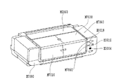
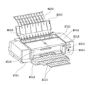
図6、図7、図11、図12、および、図13は、本実施形態で適用する記録装置の斜視図である。図6は記録装置の非使用状態、図7は記録装置M1の使用状態の前面状態、図11はフラットパス印字時の前面状態、図12は記録装置の非使用時の背面状態、図13はフラットパス印字時の背面状態をそれぞれ示している。また、図8〜図10、図14〜図17は、記録装置本体の内部機構を説明するための図である。図8は右上部からの斜視図、図9は左上部からの斜視図および図10は記録装置本体の側断面図、図14はフラットパス印字時の断面図、図15はウェット液転写部の斜視図、図16、17はウェット液転写部の断面図をそれぞれ示したものである。
給紙部は記録媒体を積載する圧板2010、記録媒体を1枚ずつ給紙する給紙ローラM2080、記録媒体を分離する分離ローラM2041、記録媒体を積載位置に戻す為の戻しレバーM2020、等がベースM2000に取り付けられる構成となっている。
(A) Paper Feed Unit FIGS. 6, 7, 11, 12, and 13 are perspective views of a recording apparatus applied in this embodiment. 6 is a non-use state of the recording apparatus, FIG. 7 is a front face state of the recording apparatus M1 in use, FIG. 11 is a front face state during flat pass printing, FIG. 12 is a back state when the recording apparatus is not in use, and FIG. The back side states during flat pass printing are shown. 8 to 10 and 14 to 17 are diagrams for explaining the internal mechanism of the recording apparatus main body. 8 is a perspective view from the upper right portion, FIG. 9 is a perspective view from the upper left portion, FIG. 10 is a side sectional view of the recording apparatus main body, FIG. 14 is a sectional view at the time of flat pass printing, and FIG. A perspective view and FIGS. 16 and 17 are sectional views of the wet liquid transfer portion, respectively.
The paper feeding unit includes a pressure plate 2010 for loading recording media, a paper feeding roller M2080 for feeding recording media one by one, a separation roller M2041 for separating the recording media, a return lever M2020 for returning the recording media to the loading position, and the like. It is configured to be attached to the base M2000.
(B)用紙搬送部
曲げ起こした板金からなるシャーシM1010には、記録媒体を搬送する搬送ローラM3060とペーパエンドセンサ(以下PEセンサと称す)E0007が回動可能に取り付けられている。搬送ローラM3060は、金属軸の表面にセラミックの微小粒がコーティングされた構成となっており、両軸の金属部分を不図示の軸受けが受ける状態で、シャーシM1010に取り付けられている。軸受けM3080と搬送ローラM3060との間には、不図示のローラテンションバネが設けられており、搬送ローラM3060を付勢することにより、回転時に適量の負荷を与えて安定した搬送が行えるようになっている。
(B) Paper Conveying Unit A conveyance roller M3060 for conveying a recording medium and a paper end sensor (hereinafter referred to as a PE sensor) E0007 are rotatably attached to a chassis M1010 made of a bent metal sheet. The conveying roller M3060 has a structure in which ceramic fine particles are coated on the surface of a metal shaft, and is attached to the chassis M1010 in a state where the metal portions of both shafts are received by bearings (not shown). A roller tension spring (not shown) is provided between the bearing M3080 and the conveyance roller M3060. By urging the conveyance roller M3060, an appropriate amount of load is applied during rotation so that stable conveyance can be performed. ing.
搬送ローラM3060には、従動する複数のピンチローラM3070が当接して設けられている。ピンチローラM3070は、ピンチローラホルダM3000に保持されているが、不図示のピンチローラバネによって付勢されることで、搬送ローラM3060に圧接し、ここで記録媒体の搬送力を生み出している。この時、ピンチローラホルダM3000の回転軸は、シャーシM1010の軸受けに取り付けられ、この位置を中心に回転する。 A plurality of driven pinch rollers M3070 are provided in contact with the transport roller M3060. The pinch roller M3070 is held by the pinch roller holder M3000, but is urged by a pinch roller spring (not shown) to be brought into pressure contact with the conveyance roller M3060, and generates a conveyance force for the recording medium. At this time, the rotation shaft of the pinch roller holder M3000 is attached to the bearing of the chassis M1010 and rotates around this position.
記録媒体が搬送されてくる入口には、記録媒体をガイドするためのペーパガイドフラッパM3030およびプラテンM3040が配設されている。また、ピンチローラホルダM3000には、PEセンサレバーM3021が設けられており、PEセンサレバーM3021は、記録媒体の先端および後端の検出をPEセンサ−E0007に伝える役割を果たす。プラテンM3040は、シャーシM1010に取り付けられ、位置決めされている。ペーパガイドフラッパM3030は、不図示の軸受け部を中心に回転可能で、シャーシM1010に当接することで位置決めされる。また、軸受け部M3031は、搬送ローラM3060と嵌合して摺動する。 A paper guide flapper M3030 and a platen M3040 for guiding the recording medium are disposed at the entrance where the recording medium is conveyed. The pinch roller holder M3000 is provided with a PE sensor lever M3021, and the PE sensor lever M3021 plays a role of transmitting the detection of the leading edge and the trailing edge of the recording medium to the PE sensor-E0007. The platen M3040 is attached to the chassis M1010 and positioned. The paper guide flapper M3030 can rotate around a bearing portion (not shown) and is positioned by contacting the chassis M1010. Further, the bearing M3031 is fitted and slid with the transport roller M3060.
搬送ローラM3060の記録媒体搬送方向における下流側には、不図示の記録ヘッドH1001が設けられている。 A recording head H1001 (not shown) is provided on the downstream side of the conveyance roller M3060 in the recording medium conveyance direction.
上記構成における搬送の過程を説明する。用紙搬送部に送られた記録媒体は、ピンチローラホルダM3000及びペーパガイドフラッパM3030に案内されて、搬送ローラM3060とピンチローラM3070とのローラ対に送られる。この時、PEセンサレバー−M3021が、記録媒体の先端を検知して、これにより記録媒体に対する記録位置が求められている。搬送ローラM3060とピンチローラM3070とからなるローラ対は、LFモータE0002の駆動により回転され、この回転により記録媒体がプラテンM3040上を搬送される。プラテンM3040には、搬送基準面となるリブが形成されており、このリブにより、記録ヘッドH1001と記録媒体表面との間のギャップが管理されている。また同時に、当該リブが、後述する排紙部と合わせて、記録媒体の波打ちを抑制する役割も果たしている。 The conveyance process in the above configuration will be described. The recording medium sent to the paper transport unit is guided by the pinch roller holder M3000 and the paper guide flapper M3030, and is sent to the roller pair of the transport roller M3060 and the pinch roller M3070. At this time, the PE sensor lever-M3021 detects the leading edge of the recording medium, and thereby the recording position with respect to the recording medium is obtained. A roller pair composed of a conveyance roller M3060 and a pinch roller M3070 is rotated by driving of the LF motor E0002, and the recording medium is conveyed on the platen M3040 by this rotation. The platen M3040 is provided with a rib serving as a conveyance reference surface, and a gap between the recording head H1001 and the recording medium surface is managed by the rib. At the same time, the ribs play a role of suppressing the undulation of the recording medium together with a paper discharge unit described later.
搬送ローラM3060が回転するための駆動力は、例えばDCモータからなるLFモータE0002の回転力が、不図示のタイミングベルトを介して、搬送ローラM3060の軸上に配設されたプーリM3061に伝達されることによって得られている。また、搬送ローラM306の軸上には、搬送ローラM3060による搬送量を検出する為のコードホイールM3062が設けられている。隣接するシャーシM1010には、コードホイールM3062に形成されたマーキングを読み取るためのエンコードセンサM3090が配設されている。尚、コードホイールM3062に形成されたマーキングは、150〜300lpi(ライン/インチ;参考値)のピッチで形成されているものとする。 The driving force for rotating the transport roller M3060 is transmitted, for example, to the pulley M3061 provided on the shaft of the transport roller M3060 via a timing belt (not shown) from the LF motor E0002 made of a DC motor. It is obtained by doing. A code wheel M3062 for detecting the amount of conveyance by the conveyance roller M3060 is provided on the axis of the conveyance roller M306. The adjacent chassis M1010 is provided with an encode sensor M3090 for reading the marking formed on the code wheel M3062. The markings formed on the code wheel M3062 are formed at a pitch of 150 to 300 lpi (line / inch; reference value).
(C)排紙部
排紙部は、第1の排紙ローラM3100および第2の排紙ローラM3110、複数の拍車M3120およびギア列などから構成されている。
(C) Paper Discharge Unit The paper discharge unit includes a first paper discharge roller M3100 and a second paper discharge roller M3110, a plurality of spurs M3120, a gear train, and the like.
第1の排紙ローラM3100は、金属軸に複数のゴム部を設けて構成されている。第1の排紙ローラM3100の駆動は、搬送ローラM3060の駆動が、アイドラギアを介して第1の排紙ローラM3100まで伝達されることによって行われている。
第2の排紙ローラM3110は、樹脂の軸にエラストマの弾性体M3111を複数取り付けた構成になっている。第2の排紙ローラM3110の駆動は、第1の排紙ローラM3100の駆動が、アイドラギアを介して伝達すること行われる。
The first paper discharge roller M3100 is configured by providing a plurality of rubber portions on a metal shaft. The first paper discharge roller M3100 is driven by transmitting the driving of the transport roller M3060 to the first paper discharge roller M3100 via an idler gear.
The second paper discharge roller M3110 has a structure in which a plurality of elastomer elastic bodies M3111 are attached to a resin shaft. The second paper discharge roller M3110 is driven by transmitting the drive of the first paper discharge roller M3100 via an idler gear.
拍車M3120は、周囲に凸形状を複数設けた例えばSUSでなる円形の薄板を樹脂部と一体としたもので、拍車ホルダM3130に複数取り付けられている。この取り付けは、コイルバネを棒状に設けた拍車バネによって行われているが、同時に拍車バネのばね力は、拍車M3120を排紙ローラM3100およびM3110に対し所定圧で当接させている。この構成によって拍車M3120は、2つの排紙ローラM3100およびM3110に従動して回転可能となっている。拍車M3120のいくつかは、第1の排紙ローラM3100のゴム部、あるいは第2の排紙ローラM3110の弾性体M3111の位置に設けられており、主に記録媒体の搬送力を生み出す役割を果たしている。また、その他のいくつかは、ゴム部M3101あるいは弾性体部M3111が無い位置に設けられ、主に記録時の記録媒体の浮き上がりを抑える役割を果たしている。 The spur M3120 is formed by integrating a circular thin plate made of, for example, SUS, which has a plurality of convex shapes around the resin portion, and is attached to the spur holder M3130. This attachment is performed by a spur spring provided with a coil spring in a rod shape. At the same time, the spring force of the spur spring causes the spur M3120 to contact the discharge rollers M3100 and M3110 with a predetermined pressure. With this configuration, the spur M3120 can be rotated following the two discharge rollers M3100 and M3110. Some of the spurs M3120 are provided at the position of the rubber portion of the first paper discharge roller M3100 or the elastic body M3111 of the second paper discharge roller M3110, and mainly play a role of generating the conveyance force of the recording medium. Yes. In addition, some others are provided at positions where the rubber part M3101 or the elastic body part M3111 is not provided, and mainly play a role of suppressing the lifting of the recording medium during recording.
また、ギア列は、搬送ローラM3060の駆動を排紙ローラM3100およびM3110に伝達する役割を果たしている。 Further, the gear train plays a role of transmitting the driving of the transport roller M3060 to the paper discharge rollers M3100 and M3110.
第1の排紙ローラM3100と第2の排紙ローラM3110の間には、不図示の紙端サポートが設けられている。紙端サポートは、記録媒体の両端を持ち上げて、第1の排紙ローラM3100の先で記録媒体を保持することにより、記録媒体に成された記録を、キャリッジの擦過などから守る役割を果たしている。具体的には、先端に不図示のコロが設けられた樹脂部材が、不図示の紙端サポートバネM3152によって付勢されて、所定の圧力でコロM3151を記録媒体に押し付けている。これにより、記録媒体の両端が持ち上げられ、こしを作り、所定の位置に保持できるように構成されている。 A paper end support (not shown) is provided between the first paper discharge roller M3100 and the second paper discharge roller M3110. The paper edge support plays a role of protecting the recording made on the recording medium from scratching of the carriage by lifting both ends of the recording medium and holding the recording medium at the tip of the first paper discharge roller M3100. . Specifically, a resin member having a roller (not shown) at the tip is urged by a paper edge support spring M3152 (not shown) to press the roller M3151 against the recording medium with a predetermined pressure. Thus, both ends of the recording medium are lifted to form a strain and can be held at a predetermined position.
以上の構成によって、画像形成された記録媒体は、第1の排紙ローラM3110と拍車M3120とのニップに挟まれ、搬送されて排紙トレイM3160に排出される。排紙トレイM3160は、複数に分割され、後述する下ケースM7080の下部に収納できる構成になっている。使用時は、引出して使用する。また、排紙トレイM3160は、先端に向けて高さが上がり、更にその両端は高い位置に保持されるよう設計されており、排出された記録媒体の積載性を向上し、記録面の擦れなどを防止している(図7)。 With the above configuration, the recording medium on which an image has been formed is sandwiched between the nip between the first discharge roller M3110 and the spur M3120, conveyed, and discharged to the discharge tray M3160. The paper discharge tray M3160 is divided into a plurality of parts and can be stored in a lower part of a lower case M7080 described later. When used, pull out. Further, the discharge tray M3160 is designed such that its height increases toward the leading end, and both ends thereof are held at high positions, improving the stackability of the discharged recording medium, rubbing the recording surface, and the like. (FIG. 7).
(D)キャリッジ部
キャリッジ部は、記録ヘッドH1001を取り付けるためのキャリッジM4000を有しており、キャリッジM4000は、ガイドシャフトM4020およびガイドレールM1011によって支持されている。ガイドシャフトM4020は、シャーシM1010に取り付けられており、記録媒体の搬送方向に対して直角方向にキャリッジM4000を往復走査させるように案内支持している。ガイドレールM1011は、シャーシM1010に一体に形成されており、キャリッジM4000の後端を保持して記録ヘッドH1001と記録媒体との隙間を維持する役割を果たしている。また、ガイドレールM1011のキャリッジM4000との摺動側には、ステンレス等の薄板からなる摺動シートM4030が張設され、記録装置の摺動音の低減化を図っている。
(D) Carriage part The carriage part has a carriage M4000 for mounting the recording head H1001, and the carriage M4000 is supported by a guide shaft M4020 and a guide rail M1011. The guide shaft M4020 is attached to the chassis M1010 and guides and supports the carriage M4000 to reciprocate in a direction perpendicular to the recording medium conveyance direction. The guide rail M1011 is formed integrally with the chassis M1010, and holds the rear end of the carriage M4000 and plays a role of maintaining a gap between the recording head H1001 and the recording medium. Further, a sliding sheet M4030 made of a thin plate of stainless steel or the like is stretched on the sliding side of the guide rail M1011 with respect to the carriage M4000 so as to reduce the sliding noise of the recording apparatus.
キャリッジM4000は、シャーシM1010に取り付けられたキャリッジモータE0001によりタイミングベルトM4041を介して駆動される。また、タイミングベルトM4041は、アイドルプーリM4042によって張設、支持されている。更に、タイミングベルトM4042は、キャリッジM4000とゴム等からなるキャリッジダンパーを介して結合されており、キャリッジモータE0001等の振動を減衰することで、記録される画像のむら等を低減している。 The carriage M4000 is driven via a timing belt M4041 by a carriage motor E0001 attached to the chassis M1010. The timing belt M4041 is stretched and supported by an idle pulley M4042. Further, the timing belt M4042 is coupled to the carriage M4000 via a carriage damper made of rubber or the like, and the unevenness of the recorded image is reduced by attenuating the vibration of the carriage motor E0001 or the like.
キャリッジM4000の位置を検出する為のエンコーダスケールE0005が、タイミングベルトM4041と平行に設けられている。エンコーダスケールE0005上には、150〜300lpiのピッチでマーキングが形成されている。当該マーキングを読み取るためのエンコーダセンサE0004(図18にて後述)が、キャリッジM4000に搭載されたキャリッジ基板E0013(図18にて後述)に設けられている。キャリッジ基板E0013には、記録ヘッドH1001と電気的な接続を行う為のヘッドンタクトE0101も設けられている。また、キャリッジM4000には、電気基板E0014から記録ヘッドH1001へ、駆動信号を伝えるための不図示のフレキシブルケーブルE0012(図18にて後述)が接続されている。 An encoder scale E0005 for detecting the position of the carriage M4000 is provided in parallel with the timing belt M4041. On the encoder scale E0005, markings are formed at a pitch of 150 to 300 lpi. An encoder sensor E0004 (described later in FIG. 18) for reading the marking is provided on a carriage substrate E0013 (described later in FIG. 18) mounted on the carriage M4000. The carriage substrate E0013 is also provided with a head contact E0101 for electrical connection with the recording head H1001. In addition, a flexible cable E0012 (not shown) for transmitting a drive signal from the electric board E0014 to the recording head H1001 is connected to the carriage M4000.
記録ヘッドH1001をキャリッジM4000に固定する為の構成として、不図示の突き当て部と、所定の位置に固定する為の不図示の押圧手段が、キャリッジM4000上に設けられている。突き当て部は、記録ヘッドH1001をキャリッジM4000に押し付けながら位置決めしている。押圧手段は、ヘッドセットレバーM4010に搭載され、記録ヘッドH1001をセットする際に、ヘッドセットレバーM4010を回転支点中心に回して、記録ヘッドH1001に作用する構成になっている。 As a configuration for fixing the recording head H1001 to the carriage M4000, an abutting portion (not shown) and a pressing means (not shown) for fixing at a predetermined position are provided on the carriage M4000. The butting portion is positioned while pressing the recording head H1001 against the carriage M4000. The pressing means is mounted on the head set lever M4010 and is configured to act on the recording head H1001 by turning the head set lever M4010 about the rotation fulcrum when setting the recording head H1001.
さらに、キャリッジM4000には、CD−R等の特殊メディアへ記録を行う際や、記録結果や用紙端部等の位置検出用として、反射型の光センサからなる位置検出センサM4090が取り付けられている。位置検出センサM4090は、発光素子より発光し、その反射光を受光することで、キャリッジM4000の現在位置を検出することができる。 Further, the carriage M4000 is provided with a position detection sensor M4090 including a reflection type optical sensor for recording on a special medium such as a CD-R or for detecting the position of a recording result or a sheet edge. . The position detection sensor M4090 can detect the current position of the carriage M4000 by emitting light from the light emitting element and receiving the reflected light.
上記構成において記録媒体に画像形成する場合、行位置に対しては、搬送ローラM3060およびピンチローラM3070からなるローラ対が、記録媒体を搬送して位置決めする。また、列位置に対しては、キャリッジモータE0001によりキャリッジM4000を上記搬送方向と垂直な方向に移動させて、記録ヘッドH1001を目的の画像形成位置に配置させる。位置決めされた記録ヘッドH1001は、電気基板E0014からの信号に従って、記録媒体に対しインクを吐出する。記録ヘッドH1001についての詳細な構成および記録システムは後述する。本実施形態の記録装置においては、記録ヘッドH1001により記録を行いながらキャリッジM4000が列方向に記録主走査を行なう。また、搬送ローラM3060により記録媒体が行方向に搬送される副走査を行なう。記録ヘッドを吐出口列と交差する主走査方向に移動させ、記録媒体を主走査方向と交差する副走査方向に搬送する。これらの記録主走査と副走査とを交互に繰り返すことにより、記録媒体上に画像を形成していく構成となっている。 When an image is formed on the recording medium in the above configuration, the roller pair including the conveyance roller M3060 and the pinch roller M3070 conveys and positions the recording medium with respect to the row position. For the row position, the carriage M4000 is moved in a direction perpendicular to the transport direction by the carriage motor E0001 to place the recording head H1001 at the target image forming position. The positioned recording head H1001 ejects ink to the recording medium in accordance with a signal from the electric substrate E0014. A detailed configuration and recording system for the recording head H1001 will be described later. In the recording apparatus of the present embodiment, the carriage M4000 performs the recording main scan in the column direction while recording is performed by the recording head H1001. Further, sub-scanning is performed in which the recording medium is conveyed in the row direction by the conveying roller M3060. The recording head is moved in the main scanning direction that intersects the ejection port array, and the recording medium is conveyed in the sub-scanning direction that intersects the main scanning direction. An image is formed on a recording medium by alternately repeating these recording main scanning and sub-scanning.
(E)クリ−ニング部
クリーニング部は、ポンプM5000、キャップM5010、ワイパーM5020、などから構成されている。ポンプM5000は、記録ヘッドH1001のクリーニングを行う。キャップM5010は、記録ヘッドH1001の乾燥を抑えるためのキャップである。また、ワイパーM5020は、記録ヘッドH1001の吐出口形成面をクリーニングするために備えられている。
(E) Cleaning unit The cleaning unit includes a pump M5000, a cap M5010, a wiper M5020, and the like. The pump M5000 cleans the recording head H1001. The cap M5010 is a cap for suppressing the drying of the recording head H1001. A wiper M5020 is provided for cleaning the ejection port forming surface of the recording head H1001.
クリーニング部には、専用のクリーニングモータE0003が配されている。クリーニングモータE0003には、不図示のワンウェイクラッチが設けられており、一方向の回転でポンプが作動し、もう一方向の回転ではワイパーM5020が動作すると同時にキャップM5010の昇降動作が作用するようになっている。 A dedicated cleaning motor E0003 is disposed in the cleaning unit. The cleaning motor E0003 is provided with a not-illustrated one-way clutch, and the pump is operated by rotation in one direction, and the wiper M5020 is operated at the same time as the wiper M5020 is operated in the other direction. ing.
ポンプM5000では、不図示のポンプコロが2本の不図示のチューブをしごくことによって負圧が発生させるように構成されている。またキャップM5010は、不図示の弁などを介してポンプM5000に接続されている。キャップM5010を記録ヘッドH1001のインク吐出口に密着させた状態で、ポンプM5000を作用させると、記録ヘッドH1001から不要なインク等が吸引されるようになっている。更にキャップM5010の内側部分には、吸引後のヘッドM6000のフェイス面に残るインクを削減する為に、キャップ吸収体M5011が設けられている。また、キャップM5010を開けた状態で、キャップM5010に残っているインクを吸引することにより、残インクによる固着およびその後の弊害が起こらないように配慮されている。なお、ポンプM5000で吸引されたインクは廃インクとなり、下ケースM7080に設けられた廃インク吸収体M7090に吸収され、ここに保持される。 The pump M5000 is configured such that a negative pressure is generated when a pump roller (not shown) squeezes two tubes (not shown). Cap M5010 is connected to pump M5000 via a valve (not shown) or the like. When the pump M5000 is operated in a state where the cap M5010 is in close contact with the ink discharge port of the recording head H1001, unnecessary ink or the like is sucked from the recording head H1001. Further, a cap absorber M5011 is provided in an inner portion of the cap M5010 in order to reduce ink remaining on the face surface of the head M6000 after suction. Further, by sucking the ink remaining in the cap M5010 with the cap M5010 opened, consideration is given to preventing the remaining ink from sticking and the subsequent adverse effects. The ink sucked by the pump M5000 becomes waste ink, is absorbed by the waste ink absorber M7090 provided in the lower case M7080, and is held here.
ワイパーM5020の動作、キャップM5010の昇降、および弁M5050の開閉など、連続して行われる一連の動作は、軸上に複数のカムを設けた不図示のメインカムによって制御される。それぞれの部位のカムやアームがメインカムに作用され、所定の動作を行うことが可能となっている。メインカムM5030の位置は、フォトインタラプタ等の位置検出センサで検出することができる。キャップM5010の降時には、ワイパーM5020がキャリッジM4000の走査方向に垂直に移動し、記録ヘッドH1001のフェイス面をクリーニングする構成となっている。ワイパーM5020は、記録ヘッドH1001のノズル近傍をクリーニングするものと、フェイス面全体をクリーニングするものと、複数設けられている。そして、キャリッジM4000が、一番奥に移動した際には、ワイパークリーナーM5060に当接することにより、ワイパーM5020自身へ付着したインクなども除去することができる構成になっている。 A series of operations continuously performed such as the operation of the wiper M5020, the raising and lowering of the cap M5010, and the opening and closing of the valve M5050 are controlled by a main cam (not shown) provided with a plurality of cams on the shaft. The cams and arms of the respective parts are acted on the main cam to perform a predetermined operation. The position of the main cam M5030 can be detected by a position detection sensor such as a photo interrupter. When the cap M5010 is lowered, the wiper M5020 moves vertically to the scanning direction of the carriage M4000 and cleans the face surface of the recording head H1001. A plurality of wipers M5020 are provided, one that cleans the vicinity of the nozzles of the recording head H1001, and one that cleans the entire face surface. When the carriage M4000 is moved to the innermost position, the ink attached to the wiper M5020 itself can be removed by contacting the wiper cleaner M5060.
(F)外装部
(A)〜(E)で説明した各ユニットは、主にシャーシM1010に組み込まれ、記録装置の機構部分を形成している。外装は、その回りを覆うように取り付けられている。外装部は主に、下ケースM7080、上ケースM7040、アクセスカバーM7030、コネクタカバーおよびフロントカバーM7010から構成されている。
(F) Exterior Unit Each unit described in (A) to (E) is mainly incorporated in the chassis M1010 to form a mechanism portion of the recording apparatus. The exterior is attached so as to cover the periphery. The exterior portion mainly includes a lower case M7080, an upper case M7040, an access cover M7030, a connector cover, and a front cover M7010.
下ケースM7080の下部には、不図示の排紙トレイレールが設けられており、分割された排紙トレイM3160が収納可能に構成されている。また、フロントカバーM7010は、非使用時に排紙口を塞ぐ構成になっている。 A lower discharge tray rail (not shown) is provided below the lower case M7080, and the divided discharge tray M3160 can be stored. Further, the front cover M7010 is configured to close the paper discharge port when not in use.
上ケースM7040には、アクセスカバーM7030が取り付けられており、回動可能に構成されている。上ケースの上面の一部は開口部を有しており、この位置で、インクタンクH1900および記録ヘッドH1001が交換可能な様に構成されている。なお、本実施形態の記録装置においては、1色のインクを吐出可能な記録ヘッドを複数色分一体的に構成した記録ヘッドユニットに対し、インクタンクH1900が色毎に独立に着脱可能なヘッドカートリッジ構成となっている。更に、上ケースには、アクセスカバーの開閉を検知する為の不図示のドアスイッチレバー、LEDの光を伝達・表示するLEDガイドM7060、基板のスイッチ(SW)に作用するキースイッチM7070等が設けられている。また、多段式の給紙トレイM2060が回動可能に取り付けられており、給紙部が使われない時は、給紙トレイM2060を収納すれることにより、給紙部のカバーにもなるように構成されている。 An access cover M7030 is attached to the upper case M7040 and is configured to be rotatable. A part of the upper surface of the upper case has an opening, and the ink tank H1900 and the recording head H1001 are configured to be replaceable at this position. In the recording apparatus of the present embodiment, a head cartridge in which the ink tank H1900 can be attached and detached independently for each color with respect to a recording head unit in which a plurality of recording heads capable of ejecting one color of ink are integrally formed. It has a configuration. Further, the upper case is provided with a door switch lever (not shown) for detecting opening / closing of the access cover, an LED guide M7060 for transmitting / displaying LED light, a key switch M7070 for acting on a switch (SW) on the board, and the like. It has been. Further, the multi-stage type paper feed tray M2060 is rotatably attached, and when the paper feed unit is not used, the paper feed tray M2060 is accommodated so that it also serves as a cover for the paper feed unit. It is configured.
上ケースM7040と下ケースM7080は、弾性を持った勘合爪で取り付けられており、その間のコネクタ部分が設けられている部分を、不図示のコネクタカバーが覆っている。 The upper case M7040 and the lower case M7080 are attached with elastic fitting claws, and a connector cover (not shown) covers a portion where the connector portion is provided therebetween.
(G)フラットパス印字部
給紙部からの給紙は、メディアが通る経路がメディアの通る方向にピンチローラに達するまで曲がっている為、メディアを給紙方向に曲げた状態で給紙をする事になる。例えば、0.5mm程度以上の厚いメディア等を給紙装置から給紙しようとすると、曲がったメディアの反力が発生し、給紙抵抗が増えて、給紙ができない場合がある。また、給紙が可能であっても、メディアが曲がったままになったり、折れたりといった事が起こる。厚いメディア等、曲げたくないメディアに印字可能にするのが、フラットバス印字である。
(G) Flat path printing unit Paper feeding from the paper feeding unit is bent until the path through which the media passes reaches the pinch roller in the media passing direction, and thus the paper is fed with the media bent in the paper feeding direction. It will be a thing. For example, when trying to feed a thick medium of about 0.5 mm or more from the paper feeding device, a reaction force of the bent media is generated, and the paper feeding resistance increases, so that the paper feeding may not be performed. Even when paper can be fed, the media may remain bent or bend. Flat bus printing allows printing on media that you do not want to bend, such as thick media.
フラットパス印字には本体背面のスリット上の開口部から(給紙装置の下)、手差しメディアを本体のピンチローらまで挿入してピンチローラにニップさせ、印字をするタイプがある。しかしながら、本件のフラットパス印字は、メディアを本体手前の排紙口から印字位置まで給紙し、スイッチバックして印字タイプである。 In flat pass printing, there is a type in which printing is performed by inserting manual feed media from the opening on the slit on the back of the main body (under the paper feeder) to the pinch rollers of the main body and niping the pinch rollers. However, the flat-pass printing in this case is a printing type in which the medium is fed from the paper discharge port on the front side of the main body to the printing position and switched back.
フロントトレイM7010は、通常記録したメディアを数十枚程度貯めて置く為に排紙部より下にある。メディアを排紙口から水平に給紙(通常の搬送方向とは反対)する為に、フロントトレイM7010を排紙口の位置まで上げる。フロントトレイM7010に図示していないフック等が付いていて、フラットパス給紙位置にフロントトレイを固定する。フロントトレイM7010がフラットパス印字位置にある事はセンサで検知する。検知したら、フラットパスモードと判断する。 The front tray M7010 is below the paper discharge unit in order to store several tens of normally recorded media. In order to feed the media horizontally from the paper discharge port (opposite the normal transport direction), the front tray M7010 is raised to the position of the paper discharge port. A hook or the like (not shown) is attached to the front tray M7010, and the front tray is fixed at the flat path feeding position. The sensor detects that the front tray M7010 is at the flat pass printing position. If detected, it is determined to be a flat path mode.
フラットパスモードでは、まず、フラットパスキーE3004を押す事によって、想定しているメディアの厚みより高く、拍車ホルダ3130とピンチローラホルダM3000を図示していない機構により持ち上げる。これにより、メディアをフロントトレイM7010に載せて、排紙口からメディアを挿入することができる。またリヤトレイボタンM7110を押す事によって、リヤトレイM7090を開く。更にリヤサブトレイM7091をV字に開く事も可能である。リヤトレイM7090、リヤサブトレイM7091は長いメディアを本体前面から挿入した場合本体背面から飛び出すので、長いメディアを本体背面でも支える為のトレイである。厚いメディアは記録中、フラットな姿勢を保たないと、ヘッド擦れの原因になったら、搬送負荷の変化から印字品位に影響を及ぼす可能性がある。
In the flat pass mode, first, by pressing a flat pass key E3004, the
このシーケンスによって、メディアは排紙口から本体内にメディアを挿入可能となる(スイッチバックで本体背面からはみ出ない長さのメディアは、リヤトレイM7090を開く必要はない)。メディアの手前側と給紙部と同じように右端をフロントトレイM7010の目印に揃えて、フロントトレイM7010に載せる。 With this sequence, the medium can be inserted into the main body from the paper discharge outlet (the medium having a length that does not protrude from the rear surface of the main body by the switchback need not open the rear tray M7090). As with the front side of the medium and the paper feeding unit, the right end is aligned with the mark of the front tray M7010 and placed on the front tray M7010.
ここでフラットパスキーE3004を押すと、拍車ホルダ3130が降りて排紙ローラM3100,3110と拍車3120でメディアをニップする。その後、排紙ローラM3100,3110でメディアを所定量本体内に引き込む(記録方向とは反対、フラットパスの給紙方向)。所定量とは、最初にメディアをセットした前後方向の位置は、メディアの手前側を揃えているので、短いメディアは搬送ローラM3060まで届いていない。想定している一番短いメディアが搬送ローラM3060に届くまでの距離が所定量である。
When the flat pass key E3004 is pressed here, the
所定量送られたメディアは搬送ローラM3060に届いているので、その位置でピンチローラホルダM3000を降ろして、搬送ローラM3060とピンチローラM3070でメディアをニップさせる。これでメディアのフラットパスでの給紙が終了した事になる(記録待機位置)。排紙ローラ3100、3110と排紙ローラのニップ力は弱いので、メディアの位置が記録するまでにずれてしまう可能性がある。搬送ローラM3060とピンチローラM3070のニップ力は高いので、メディアのセット位置がしっかり決まった事になる。また、所定量メディアを本体内に送る時、プラテンM3040と拍車ホルダM3130の間にあるフラットパス紙検知センサM3170で用紙の手前の位置を検知する。
Since the medium fed by a predetermined amount has reached the transport roller M3060, the pinch roller holder M3000 is lowered at that position, and the medium is nipped by the transport roller M3060 and the pinch roller M3070. This completes the media feeding in the flat path (recording standby position). Since the nip force between the
記録待機状態で記録コマンドを実行する事になる。記録位置まで搬送ローラM3060でメディアを搬送し、後は通常の記録と同じように記録を行い、記録後フロントトレイM3010に排紙する事になる。 The recording command is executed in the recording standby state. The medium is transported to the recording position by the transport roller M3060, and then recording is performed in the same manner as normal recording. After recording, the medium is discharged to the front tray M3010.
フラットパス印字で更に印字を続けたい場合は、記録したメディアをフロントトレイM7010から取り出す。後は前述したシーケンスを繰り返す。具体的には、フラットパスキーE3004を押す事によって、拍車ホルダM3130とピンチローラホルダM3000を持ち上げて、メディアをセットすることから始まる。 If it is desired to continue printing with flat pass printing, the recorded medium is taken out from the front tray M7010. After that, the above sequence is repeated. Specifically, it starts by raising the spur holder M3130 and the pinch roller holder M3000 by pressing the flat pass key E3004 and setting the media.
フラットパス印字を終了する場合は、フロントトレイM7010を通常記録位置に戻す事によって、通常記録モードに戻る。 When the flat pass printing is finished, the normal recording mode is restored by returning the front tray M7010 to the normal recording position.
本発明で取り上げているファインアート用紙は、既に述べているように、紙の厚みが0.3から0.5mm程度の比較的厚い用紙が多い。このため、ここで記載しているフラットパス印字部を用いて給紙を行うことで、給紙時の不送りの発生を防止したり、記録ヘッドが記録媒体表面を擦るヘッド擦れの回避も可能となる。 As described above, the fine art paper taken up in the present invention is often a relatively thick paper having a thickness of about 0.3 to 0.5 mm. For this reason, feeding by using the flat path printing unit described here can prevent the occurrence of non-feed during feeding or avoid head rubbing where the recording head rubs the surface of the recording medium. It becomes.
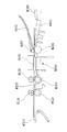
(H)ウェット液転写部
主に顔料インクのみを使用している場合、顔料インクが吐出口面に付着したままワイピングスすると吐出口面を傷つけ易い。
そこで、ブレードM5020に溶液を付着させ、その後に濡れたブレードM5020をワイピングする事で、顔料インクによる吐出口面の劣化を防ぐのが、ウェットワイピングである。
(H) Wet liquid transfer portion When only pigment ink is mainly used, wiping with the pigment ink attached to the discharge port surface tends to damage the discharge port surface.
Therefore, wet wiping prevents the deterioration of the discharge port surface due to the pigment ink by attaching a solution to the blade M5020 and then wiping the wet blade M5020.
M5090はウェット液タンクで、ブレードに付着させる、例えばグリセリン溶液等が入っている。M5100はウェット液保持部材で、ウェット液がウェット液タンクM5090から漏れない様に適度な表面張力を有する繊維質部材等であり、ウェット液を染み込ませている。 M5090 is a wet liquid tank that contains, for example, a glycerin solution to be attached to the blade. M5100 is a wet liquid holding member, which is a fibrous member having an appropriate surface tension so that the wet liquid does not leak from the wet liquid tank M5090, and soaks in the wet liquid.
M5080はウェット液転写部材でブレードと接触するウェット液転写部M5081を有している。例えば、多孔質であって適度な毛管力を備えた材質である。ウェット液転写部材M5080はウェット液が染み込んだウェット液保持部材M5090と接しているので、ウェット液転写部材M5080もウェット液が染み込むことになる。ウェット液転写部材M5080はウェット液が残り少なくなっても、ウェット液転写部M5081へウェット液を供給出来るだけの毛管力を有した材質である。 M5080 is a wet liquid transfer member and has a wet liquid transfer portion M5081 that contacts the blade. For example, the material is porous and has an appropriate capillary force. Since the wet liquid transfer member M5080 is in contact with the wet liquid holding member M5090 soaked with the wet liquid, the wet liquid transfer member M5080 is also soaked with the wet liquid. The wet liquid transfer member M5080 is made of a material having a capillary force that can supply the wet liquid to the wet liquid transfer portion M5081 even when the remaining wet liquid is low.
キャリッジM4000がブレードM5020に触れない位置に退避している位置にいる時に、ブレードM5020はブレードクリーナM5060を潜り抜けて(−Y方向)、ウェット液転写部M5081に接触させる(図16)。適度な時間接触することで、ブレードM5020にウェット液が適量転写される事になる。 When the carriage M4000 is in a position where it is retracted to a position where it does not touch the blade M5020, the blade M5020 penetrates the blade cleaner M5060 (−Y direction) and contacts the wet liquid transfer portion M5081 (FIG. 16). By contacting for an appropriate time, an appropriate amount of wet liquid is transferred to the blade M5020.
次にブレードM5020は+Y方向に移動するが、ブレードクリーナM5060に触れるのはウェット液が転写していない方の面なので、ウェット液はブレードM5020に転写されたままになる。 Next, the blade M5020 moves in the + Y direction, but the wet cleaner remains transferred to the blade M5020 because it touches the blade cleaner M5060 on the surface where the wet fluid is not transferred.
ブレードをワイピング開始位置まで戻した後、キャリッジM4000をワイピング位置まで移動さる。再度、ブレードM5020を−Y方向に移動させる事によって、ウェット液が付いた面で記録ヘッドH1001をワイピングする事が可能となる。 After returning the blade to the wiping start position, the carriage M4000 is moved to the wiping position. By moving the blade M5020 in the −Y direction again, the recording head H1001 can be wiped on the surface with the wet liquid.
ブレードM5020に溶液を付着させ、その後に濡れたブレードM5020をワイピングする事で、顔料インクの吐出口面に対する劣化を防ぐ事が可能となり、顔料インクのみでのワイピングが可能となった。 By causing the solution to adhere to the blade M5020 and then wiping the wet blade M5020, it is possible to prevent deterioration of the discharge port surface of the pigment ink, and wiping with only the pigment ink is possible.
3.対応記録メディア
ここで、本実施形態の記録装置が対応する記録媒体(メディア)の種類について触れる。インクジェットプリンタは記録するメディアを選ばないことが大きなメリットの一つとなっている。例えば、普通紙やコート紙、光沢紙といった一般的なメディアはもとより、はがきや名刺のような小サイズの用紙にも記録が可能である。また、インク受容層が表層にコーティングされたプリンタブルCDやプリンタブルDVDのような特殊な形状をしたメディアにも専用のトレイを用いることで記録が可能となる。また、前述のように、本実施形態における記録装置は、フラットパス機構を有しており、ファインアート紙のような比較的厚いメディア、およびボード紙のような曲げることのできないメディアにも記録が可能である。
3. Corresponding Recording Medium Here, the type of recording medium (medium) supported by the recording apparatus of the present embodiment will be described. One of the major advantages of inkjet printers is that they do not choose the recording media. For example, recording can be performed not only on general media such as plain paper, coated paper, and glossy paper, but also on small-size paper such as postcards and business cards. In addition, recording can be performed on a specially shaped medium such as a printable CD or a printable DVD having an ink receiving layer coated on the surface layer by using a dedicated tray. Further, as described above, the recording apparatus according to the present embodiment has a flat path mechanism, and can record on relatively thick media such as fine art paper and media that cannot be bent such as board paper. Is possible.
ここで述べたファインアート紙については、基材にコットン繊維を用いた中性紙を採用し紙自体の保存性を高めている。また、通常のインクジェット用紙に含まれている、紙の白色度を向上させる蛍光増白剤が含まれているが、長期間保存すると紙が黄変してしまう問題があるため、ファインアート紙にはこの蛍光増白剤を用いない場合が多い。一方、ファインアート紙の特性として、紙の繊維同士の結合力(内部結合強度)が弱いため、繊維が紙表面から分離し、紙紛となり易い。 As for the fine art paper described here, neutral paper using cotton fibers as a base material is adopted to enhance the preservability of the paper itself. In addition, it contains a fluorescent brightening agent that is included in normal inkjet paper to improve the whiteness of the paper. Often do not use this optical brightener. On the other hand, as a characteristic of fine art paper, since the bond strength (internal bond strength) between paper fibers is weak, the fibers are easily separated from the paper surface and easily become paper dust.
4.電気回路構成
次に本実施形態における電気的回路の構成を説明する。
4). Next, the configuration of the electrical circuit in this embodiment will be described.
図18は、記録装置J0013における電気的回路の全体構成を概略的に説明するためのブロック図である。本実施形態で適用する記録装置では、主にキャリッジ基板E0013、メイン基板E0014、電源ユニットE0015およびフロントパネルE0106等によって構成されている。 FIG. 18 is a block diagram for schematically explaining the overall configuration of the electrical circuit in the recording apparatus J0013. The recording apparatus applied in the present embodiment is mainly configured by a carriage substrate E0013, a main substrate E0014, a power supply unit E0015, a front panel E0106, and the like.
ここで、電源ユニットE0015は、メイン基板E0014と接続され、各種駆動電源を供給するものとなっている。 Here, the power supply unit E0015 is connected to the main board E0014 and supplies various driving powers.
キャリッジ基板E0013は、キャリッジM4000に搭載されたプリント基板ユニットであり、ヘッドコネクタE0101を通じて記録ヘッドH1001との信号の授受、ヘッド駆動電源の供給を行うインターフェースとして機能する。ヘッド駆動電源の制御に供する部分として、記録ヘッドH1001の各色吐出部に対する複数チャネルのヘッド駆動電圧変調回路E3001を有しする。そして、フレキシブルフラットケーブル(CRFFC)E0012を通じてメイン基板E0014から指定された条件に従ってヘッド駆動電源電圧を発生する。また、キャリッジM4000の移動に伴ってエンコーダセンサE0004から出力されるパルス信号に基づいて、エンコーダスケールE0005とエンコーダセンサE0004との位置関係の変化を検出する。更にその出力信号をフレキシブルフラットケーブル(CRFFC)E0012を通じてメイン基板E0014へと出力する。 The carriage substrate E0013 is a printed circuit board unit mounted on the carriage M4000, and functions as an interface for exchanging signals with the recording head H1001 and supplying head drive power through the head connector E0101. As a portion for controlling the head drive power supply, a head drive voltage modulation circuit E3001 having a plurality of channels for the respective color ejection portions of the recording head H1001 is provided. Then, a head drive power supply voltage is generated according to a specified condition from the main board E0014 through a flexible flat cable (CRFFC) E0012. Further, a change in the positional relationship between the encoder scale E0005 and the encoder sensor E0004 is detected based on the pulse signal output from the encoder sensor E0004 as the carriage M4000 moves. Further, the output signal is output to the main board E0014 through a flexible flat cable (CRFFC) E0012.
キャリッジ基板E0013には、図20に示すように、2つの発光素子(LED)E3011および受光素子E3013でなる光学センサE3010および周囲温度を検出するためのサーミスタE3020が接続されている。以下、これらのセンサをマルチセンサE3000として参照する。マルチセンサE3000により得られる情報は、フレキシブルフラットケーブル(CRFFC)E0012を通じてメイン基板E0014へと出力される。 As shown in FIG. 20, an optical sensor E3010 composed of two light emitting elements (LEDs) E3011 and a light receiving element E3013 and a thermistor E3020 for detecting the ambient temperature are connected to the carriage substrate E0013. Hereinafter, these sensors are referred to as a multi-sensor E3000. Information obtained by the multi-sensor E3000 is output to the main board E0014 through a flexible flat cable (CRFFC) E0012.
メイン基板E0014は、本実施形態におけるインクジェット記録装置の各部の駆動制御を司るプリント基板ユニットである。その基板上にホストインタフェース(ホストI/F)E0017を有しており、不図示のホストコンピュータからの受信データをもとに記録動作の制御を行う。また、キャリッジモータE0001、LFモータE0002、APモータE3005、PRモータE3006など、各種モータと接続されて各機能の駆動を制御している。キャリッジモータE0001は、キャリッジM4000を主走査させるための駆動源となるモータである。LFモータE0002、記録媒体を搬送するための駆動源となるモータである。APモータE3005は、記録ヘッドH1001の回復動作および記録媒体の給紙動作の駆動源となるモータである。PRモータE3006は、フラットパス記録動作の駆動源となるモータである。さらに、PEセンサ、CRリフトセンサ、LFエンコーダセンサ、PGセンサのような、プリンタ各部の動作状態を検出する様々なセンサに対して、制御信号および検出信号の送受信を行うためのセンサ信号E0104に接続される。また、メイン基板E0014は、CRFFC E0012および電源ユニットE0015にそれぞれ接続されるとともに、さらにパネル信号E0107を介してフロントパネルE0106と情報の授受を行うためのインターフェースを有している。 The main substrate E0014 is a printed circuit board unit that controls driving of each part of the ink jet recording apparatus according to the present embodiment. A host interface (host I / F) E0017 is provided on the board, and a recording operation is controlled based on data received from a host computer (not shown). Further, it is connected to various motors such as a carriage motor E0001, an LF motor E0002, an AP motor E3005, and a PR motor E3006 to control driving of each function. The carriage motor E0001 is a motor serving as a drive source for main-scanning the carriage M4000. The LF motor E0002 is a motor serving as a drive source for transporting the recording medium. The AP motor E3005 is a motor that is a driving source for the recovery operation of the recording head H1001 and the recording medium feeding operation. The PR motor E3006 is a motor serving as a drive source for the flat pass recording operation. Furthermore, it connects to the sensor signal E0104 for transmitting and receiving control signals and detection signals to various sensors that detect the operating state of each part of the printer, such as PE sensors, CR lift sensors, LF encoder sensors, and PG sensors. Is done. The main board E0014 is connected to each of the CRFFC E0012 and the power supply unit E0015, and further has an interface for exchanging information with the front panel E0106 via a panel signal E0107.
フロントパネルE0106は、ユーザ操作の利便性のために、記録装置本体の正面に設けたユニットである。これは、リジュームキーE0019、LED E0020、電源キーE0018およびフラットパスキーE3004を有するほか(図6)、さらにデジタルカメラ等の周辺デバイスとの接続に用いるデバイスI/F E0100を有している。
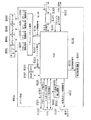
図19は、メイン基板E1004の内部構成を示すブロック図である。
The front panel E0106 is a unit provided in front of the recording apparatus main body for the convenience of user operation. This has a resume key E0019, LED E0020, power key E0018, and flat pass key E3004 (FIG. 6), and also has a device I / F E0100 used for connection with peripheral devices such as a digital camera.
FIG. 19 is a block diagram showing an internal configuration of the main board E1004.
図において、E1102はASIC(Application Specific Integrated Circuit)である。これは、制御バスE1014を通じてROM E1004に接続され、ROM E1004に格納されたプログラムに従って、各種制御を行っている。例えば、各種センサに関連するセンサ信号E0104や、マルチセンサE3000に関連するマルチセンサ信号E4003の送受信を行う。そのほか、エンコーダ信号E1020、フロントパネルE0106上の電源キーE0018、リジュームキーE0019およびフラットパスキーE3004からの出力の状態を検出している。また、ホストI/F E0017、フロントパネル上のデバイスI/F E0100の接続およびデータ入力状態に応じて、各種論理演算や条件判断等を行い、各構成要素を制御し、インクジェット記録装置の駆動制御を司っている。 In the figure, E1102 is an ASIC (Application Specific Integrated Circuit). This is connected to the ROM E1004 through the control bus E1014, and performs various controls according to the program stored in the ROM E1004. For example, the sensor signal E0104 related to various sensors and the multi-sensor signal E4003 related to the multi-sensor E3000 are transmitted and received. In addition, the output state from the encoder signal E1020, the power key E0018 on the front panel E0106, the resume key E0019 and the flat pass key E3004 is detected. Also, according to the connection and data input state of the host I / F E0017 and the device I / F E0100 on the front panel, various logical operations and condition judgments are performed, each component is controlled, and drive control of the ink jet recording apparatus is performed. I am in charge.
E1103はドライバ・リセット回路である。これは、ASIC E1102からのモータ制御信号E1106に従って、CRモータ駆動信号E1037、LFモータ駆動信号E1035、APモータ駆動信号E4001およびPRモータ駆動信号E4002を生成し、各モータを駆動する。さらに、ドライバ・リセット回路E1103は、電源回路を有しており、メイン基板E0014、キャリッジ基板E0013、フロントパネルE0106など各部に必要な電源を供給する。さらには電源電圧の低下を検出して、リセット信号E1015を発生および初期化を行う。 E1103 is a driver reset circuit. This generates a CR motor drive signal E1037, an LF motor drive signal E1035, an AP motor drive signal E4001 and a PR motor drive signal E4002 in accordance with the motor control signal E1106 from the ASIC E1102, and drives each motor. Further, the driver / reset circuit E1103 has a power supply circuit, and supplies necessary power to each part such as the main board E0014, the carriage board E0013, and the front panel E0106. Further, a decrease in power supply voltage is detected, and a reset signal E1015 is generated and initialized.
E1010は電源制御回路であり、ASIC E1102からの電源制御信号E1024に従って発光素子を有する各センサ等への電源供給を制御する。 E1010 is a power supply control circuit that controls power supply to each sensor having a light emitting element in accordance with a power supply control signal E1024 from the ASIC E1102.
ホストI/F E0017は、ASIC E1102からのホストI/F信号E1028を、外部に接続されるホストI/FケーブルE1029に伝達し、またこのケーブルE1029からの信号をASIC E1102に伝達する。 The host I / F E0017 transmits a host I / F signal E1028 from the ASIC E1102 to a host I / F cable E1029 connected to the outside, and transmits a signal from the cable E1029 to the ASIC E1102.
一方、電源ユニットE0015からは電力が供給される。供給された電力は、メイン基板E0014内外の各部へ、必要に応じて電圧変換された上で供給される。また、ASIC E1102からの電源ユニット制御信号E4000が電源ユニットE0015に接続され、記録装置本体の低消費電力モード等を制御する。 On the other hand, power is supplied from the power supply unit E0015. The supplied power is supplied to each part inside and outside the main board E0014 after voltage conversion as necessary. A power supply unit control signal E4000 from the ASIC E1102 is connected to the power supply unit E0015, and controls a low power consumption mode and the like of the recording apparatus main body.
ASIC E1102は1チップの演算処理装置内蔵半導体集積回路であり、前述したモータ制御信号E1106、電源制御信号E1024および電源ユニット制御信号E4000等を出力する。そして、ホストI/F E0017との信号の授受を行うとともに、パネル信号E0107を通じて、フロントパネル上のデバイスI/F E0100との信号の授受を行う。さらに、センサ信号E0104を通じてPEセンサ、ASFセンサ等各部センサ類により状態を検知する。さらに、マルチセンサ信号E4003を通じてマルチセンサE3000を制御するとともに状態を検知する。またパネル信号E0107の状態を検知して、パネル信号E0107の駆動を制御してフロントパネル上のLED E0020の点滅を行う。 The ASIC E1102 is a one-chip semiconductor integrated circuit with an arithmetic processing unit, and outputs the motor control signal E1106, the power supply control signal E1024, the power supply unit control signal E4000, and the like described above. Then, signals are exchanged with the host I / F E0017, and signals are exchanged with the device I / F E0100 on the front panel through the panel signal E0107. Further, the state is detected by each sensor such as a PE sensor and an ASF sensor through a sensor signal E0104. Further, the multi-sensor E3000 is controlled through the multi-sensor signal E4003 and the state is detected. Further, the state of the panel signal E0107 is detected, the driving of the panel signal E0107 is controlled, and the LED E0020 on the front panel blinks.
さらにASIC E1102は、エンコーダ信号(ENC)E1020の状態を検知してタイミング信号を生成し、ヘッド制御信号E1021で記録ヘッドH1001とのインターフェースをとり記録動作を制御する。ここにおいて、エンコーダ信号(ENC)E1020はCRFFC E0012を通じて入力されるエンコーダセンサE0004の出力信号である。また、ヘッド制御信号E1021は、フレキシブルフラットケーブルE0012を通じてキャリッジ基板E0013に接続される。そして、前述のヘッド駆動電圧変調回路E3001およびヘッドコネクタE0101を経て記録ヘッドH1001に供給されるとともに、記録ヘッドH1001からの各種情報をASIC E1102に伝達する。
このうち吐出部毎のヘッド温度情報については、メイン基板上のヘッド温度検出回路E3002で信号増幅された後、ASIC E1102に入力され、各種制御判断に用いられる。
Further, the ASIC E1102 detects the state of the encoder signal (ENC) E1020 to generate a timing signal, and controls the recording operation by interfacing with the recording head H1001 using the head control signal E1021. Here, the encoder signal (ENC) E1020 is an output signal of the encoder sensor E0004 inputted through the CRFFC E0012. The head control signal E1021 is connected to the carriage substrate E0013 through the flexible flat cable E0012. Then, the information is supplied to the recording head H1001 via the head drive voltage modulation circuit E3001 and the head connector E0101, and various information from the recording head H1001 is transmitted to the ASIC E1102.
Among these, the head temperature information for each ejection unit is amplified by the head temperature detection circuit E3002 on the main substrate, and then input to the ASIC E1102 to be used for various control determinations.
図中、E3007はDRAMであり、記録用のデータバッファ、ホストコンピュータからの受信データバッファ等として、また各種制御動作に必要なワーク領域しても使用されている。 In the figure, E3007 is a DRAM, which is used as a data buffer for recording, a data buffer received from the host computer, etc., and also as a work area necessary for various control operations.
4.記録ヘッド部構成
以下に本実施形態で適用するヘッドカートリッジH1000の構成について説明する。
本実施形態におけるヘッドカートリッジH1000は、記録ヘッドH1001と、インクタンクH1900を搭載する手段およびインクタンクH1900から記録ヘッドにインクを供給するための手段を有している。そして、キャリッジM4000に対して着脱可能に搭載される。
4). Configuration of Recording Head Unit The configuration of the head cartridge H1000 applied in the present embodiment will be described below.
The head cartridge H1000 in this embodiment has a recording head H1001, means for mounting the ink tank H1900, and means for supplying ink from the ink tank H1900 to the recording head. Then, it is detachably mounted on the carriage M4000.
図21は、本実施形態で適用するヘッドカートリッジH1000に対し、インクタンクH1900を装着する様子を示した図である。本実施形態の記録装置は、10色の顔料インクによって画像を形成する。10色とはシアン(C)、ライトシアン(Lc)、マゼンタ(M)、ライトマゼンタ(Lm)、イエロー(Y)、第1ブラック(K1)、第2ブラック(K2)、レッド(R)、グリーン(G)およびグレー(Gray)である。従ってインクタンクT0001もこれら10色分のものが独立に用意されている。そして、図に示すように、インクタンクそれぞれがヘッドカートリッジH1000に対して着脱自在となっている。なお、インクタンクH1900の着脱は、キャリッジM4000にヘッドカートリッジH1000が搭載された状態で行えるようになっている。 FIG. 21 is a diagram illustrating a state in which the ink tank H1900 is attached to the head cartridge H1000 applied in the present embodiment. The recording apparatus of the present embodiment forms an image with 10 color pigment inks. The ten colors are cyan (C), light cyan (Lc), magenta (M), light magenta (Lm), yellow (Y), first black (K1), second black (K2), red (R), and green. (G) and Gray. Accordingly, the ink tank T0001 is prepared for these 10 colors independently. As shown in the figure, each ink tank is detachable from the head cartridge H1000. The ink tank H1900 can be attached and detached while the head cartridge H1000 is mounted on the carriage M4000.
本実施形態で用いる記録ヘッドH1001に関して、各インク色毎の吐出口列を模式的に示した図22を用いて説明する。本図は記録ヘッドH1001の吐出口面側から見たときの吐出口列の並びを示しており、本実施形態の記録ヘッドは401と402の2つのチップから構成されている。さらに各チップには、それぞれ5色のインクを吐出するための吐出口列が2列ずつ配置されている。チップ401には、LM、K1、K2、LC、Grayのインクを吐出するための吐出口列が各々2列ずつ、すなわち計10列の吐出口列が並列に配置されている。同様にチップ402にはY、M、G、R、Cのインクを吐出するための吐出口列が各々2列ずつ、すなわち計10列の吐出口列が並列に配置されている。各インク色毎に2列ずつの吐出口列において、吐出口600dpiに相当するピッチ(P)で配列されている。また、2列間における吐出口は1200dpiに相当するピッチ(P/2)ずつずらして配置されている。図中、吐出口の番号を0から767番まで割り振った場合、LM_eは、0,2,4、・・・766の偶数番目の吐出口が配置された偶数列を示している。同様にLM_oは、1,3,5・・・767の奇数番目の吐出口が配列された奇数列を示している。以下、他のインク色についても同様に、それぞれ偶数列・奇数列の2列の吐出口列が形成されている。
The recording head H1001 used in this embodiment will be described with reference to FIG. 22 schematically showing the ejection port array for each ink color. This figure shows the arrangement of the ejection port array when viewed from the ejection port surface side of the recording head H1001, and the recording head of this embodiment is composed of two
5.記録動作
図23は、本発明の第1の実施形態における、記録方法を示すフローチャートである。ホスト装置のプリンタドライバで用紙種類や記録品位、記録部数の設定を行ったあとに記録命令が発行され、本実施形態における記録方法が開始される(S301)。ステップS302において、図2に示した記録データ中のメディア情報の検出を行う。すなわち、選択されたメディア(記録媒体)が光沢紙やコート紙などの記録時に飛散物の発生量の少ないメディアなのか、ファインアート紙のように記録時に飛散物の発生量の多いメディアなのかを判別する。
5. Recording Operation FIG. 23 is a flowchart showing a recording method according to the first embodiment of the present invention. After setting the paper type, recording quality, and the number of copies by the printer driver of the host device, a recording command is issued, and the recording method in this embodiment is started (S301). In step S302, the media information in the recording data shown in FIG. 2 is detected. That is, whether the selected medium (recording medium) is a medium that generates a small amount of scattered matter during recording, such as glossy paper or coated paper, or a medium that generates a large amount of scattered material during recording, such as fine art paper. Determine.
次にステップS303で記録媒体を給紙する。このときファインアート紙のような比較的厚みのあるメディアについては前述のフラットパス部から給紙を行い、それ以外の比較的薄いメディアについては、既に機構部の構成で説明を行った給紙部より給紙を行う。 In step S303, the recording medium is fed. At this time, a relatively thick medium such as fine art paper is fed from the above-mentioned flat path section, and the other relatively thin media is fed by the structure of the mechanism section described above. Feed more.
ステップS304では、S302で検出したメディア情報の内容を基に、ファインアート紙か否かの判定を行う。ここで、ファインアート紙と判定された場合には、ステップS306に移行し、後述する紙粉の発生しにくい分割記録方法による記録(分割記録)を行う。このステップS306では、まず、隣接する吐出口列(LM_e、LM_o)における複数の吐出口のうち、ファインアート紙の記録に使用する吐出口を決定する。その後、こうして決定された吐出口を使用して分割記録を行う。一方、ファインアート紙以外の紙粉の発生がほとんどないメディアであった場合には、ステップS305に移行し、通常の記録方式による記録(通常記録)を行う。このステップS305では、まず、隣接する吐出口列(LM_e、LM_o)における複数の吐出口のうち、ファインアート紙以外の用紙の記録に使用する吐出口を決定する。その後、こうして決定された吐出口を使用して通常記録を行う。 In step S304, based on the content of the media information detected in S302, it is determined whether or not the paper is fine art paper. If it is determined that the paper is fine art paper, the process proceeds to step S306, and recording (divided recording) is performed by a divided recording method in which paper dust is less likely to be generated, which will be described later. In step S306, first, among the plurality of discharge ports in the adjacent discharge port arrays (LM_e, LM_o), the discharge ports used for recording fine art paper are determined. Thereafter, divisional recording is performed using the ejection ports thus determined. On the other hand, in the case of a medium that hardly generates paper dust other than fine art paper, the process proceeds to step S305, and recording by a normal recording method (normal recording) is performed. In this step S305, first, among the plurality of discharge ports in the adjacent discharge port arrays (LM_e, LM_o), the discharge ports used for recording paper other than fine art paper are determined. Thereafter, normal recording is performed using the ejection ports thus determined.
ここでS305の通常記録とS306の分割記録の記録方法の違いを説明する。S306では、ファインアート紙のような紙粉が発生しやすいメディアであることから、分割記録を行なう。すなわち、2列の吐出口列の気流による紙粉の舞い上がりを軽減するため、それぞれのインク色毎において、2列ある吐出口列のうち、片方の吐出口列を使用して記録走査(スキャン)し、使用する吐出口列はスキャン毎に交互に変更する。具体的に、図22に示した記録ヘッドの吐出口列の内、LMインクに着目して説明する。LMの2つの吐出口列、すなわち偶数列LM_eと奇数列のLM_oにおいて、第n番目のスキャンでは偶数列のLM_eを用い、次のn+1番目のスキャンでは奇数列のLM_oを用いて記録を行う。 Here, the difference in the recording method between the normal recording in S305 and the divided recording in S306 will be described. In S306, since it is a medium that easily generates paper dust such as fine art paper, division recording is performed. That is, in order to reduce the rise of paper dust due to the airflow of the two ejection port arrays, recording scanning (scanning) is performed using one of the two ejection port arrays for each ink color. The discharge port array to be used is changed alternately every scan. Specifically, the description will be made by paying attention to the LM ink in the ejection port array of the recording head shown in FIG. In the two ejection port rows of LM, that is, the even-numbered row LM_e and the odd-numbered row LM_o, printing is performed using the even-numbered row LM_e in the n-th scan and the odd-numbered row LM_o in the next n + 1-th scan.
例えば、記録する際のマルチパスのパス数が8パスであった場合には、1回のパスにおける記録画像の間引き率は、平均して各インク色当たり12.5%となる。S305の通常記録の場合には、どちらのノズル列も1パス目から8パス目までの平均間引き率は全て12.5%となる。一方、S306の分割記録のように偶数列と奇数列を交互に使用する場合には、1パス目から8パス目までの偶数列の平均間引き率は、25%、0%、25%、0%、25%、0%、25%、0%となる。一方、奇数列は、0%、25%、0%、25%、0%、25%、0%、25%となる。 For example, when the number of multi-pass passes during printing is 8, the print image thinning rate in one pass averages 12.5% for each ink color. In the case of normal printing in S305, the average thinning rate from the first pass to the eighth pass is 12.5% for both nozzle rows. On the other hand, when even and odd columns are used alternately as in the divided recording of S306, the average thinning rate of the even columns from the first pass to the eighth pass is 25%, 0%, 25%, 0 %, 25%, 0%, 25%, and 0%. On the other hand, the odd-numbered columns are 0%, 25%, 0%, 25%, 0%, 25%, 0%, and 25%.
このように本実施形態では、紙粉が発生しやすいメディアに対して記録を行う場合と紙粉が発生しにくいメディアに対して記録を行う場合とで使用可能な吐出口を変更している。詳しくは、紙粉が発生しやすいメディアについては、相対移動中に、吐出口の配列方向と交差する方向に沿って隣接する2つの吐出口列(隣接吐出口)に属する吐出口のうち使用可能な吐出口の数を制限することで、紙粉の発生量を軽減している。 As described above, in the present embodiment, the discharge ports that can be used are changed depending on whether recording is performed on a medium that easily generates paper dust or recording is performed on a medium that does not easily generate paper dust. Specifically, media that easily generate paper dust can be used among the discharge ports belonging to two adjacent discharge port arrays (adjacent discharge ports) along the direction intersecting the discharge port arrangement direction during relative movement. The amount of paper dust generated is reduced by limiting the number of discharge ports.
このような記録方法により、入力された記録データの全ての記録が終了すると、ステップS307に移行してメディアを排紙し、S308で記録処理を終了する。図24(a)および図24(b)は、2列の吐出口列を同時に使用した場合と、1列ずつ使用した場合の紙粉の舞い上がりを説明する図である。本図は、記録ヘッドの主走査方向に直交する方向から、記録ヘッドと記録メディアの間の空間の断面を示す図である。 When all the recording of the input recording data is completed by such a recording method, the process proceeds to step S307, the medium is discharged, and the recording process is ended in S308. FIG. 24A and FIG. 24B are diagrams for explaining the rise of paper dust when two ejection port arrays are used simultaneously and when each one is used. This figure is a diagram showing a cross section of the space between the recording head and the recording medium from a direction orthogonal to the main scanning direction of the recording head.
図24(a)は、偶数列と奇数列のノズル列を両方同時に使用した時に生じる気流と、それによって紙粉がどのように舞い上がるかを説明する図である。記録ヘッド201に配列された偶数列の吐出口列202と奇数列の吐出口列203は、1200dpiの12画素分、すなわち254μmの間隔が空けられている。204、205は偶数列、奇数列の各吐出口からのインク液滴の吐出の影響で発生する気流を模式的に示したものである。図示するように記録ヘッドから紙面に向かって下向きの気流が発生する。この下向きの気流は記録ヘッドと紙の間の空気抵抗によってその力は減衰されるが、紙面に到達した気流は、207や208に示すように記録ヘッド側に向かって上昇する気流となる。この上昇気流によって紙面上に存在する紙粉が209のように舞い上がって記録ヘッドと紙面間を浮遊することとなる。しかしながら、この2つの吐出口列の外側に生じる気流207と208で舞い上がった紙粉は、後続のインク液滴の吐出によって生じる下向きの気流204、205によって押し戻されて、記録ヘッドにまでは到達しない。一方、2つの吐出口列に挟まれた領域は、下向きの気流の影響で減圧された状態となり、紙面から舞い上がった上昇気流206はあまり減衰されず、外側の気流に比較して記録ヘッド面近傍まで到達することとなる。したがって、この206の気流によって舞い上がった紙粉は、記録ヘッドの吐出口近傍にまで舞い上がって浮遊する。しかも、2列の吐出口列の間の空間は204、205の2列の気流によって閉じられた空間となり、舞い上がった紙粉は閉じ込められた状態となり、引いては吐出口近傍への付着しやすい状態へとつながる。
FIG. 24A is a diagram for explaining the airflow generated when both the even-numbered and odd-numbered nozzle rows are used at the same time, and how the paper dust rises accordingly. The even-numbered
一方、図24(b)は奇数列のみを用いた場合の気流の流れと、紙粉の舞い上がり状態を模式的に示したものである。奇数列203のみを用いることで、気流によって舞い上がった紙粉は、後続のインク液滴の吐出によって発生する下向きの気流によって押し戻されるため、記録ヘッドまでは到達しない。このため、紙粉の吐出口近傍への付着は発生しない。
On the other hand, FIG. 24B schematically shows the flow of airflow and the rising state of paper dust when only odd rows are used. By using only the odd-numbered
このように隣接する吐出口列のうち、同一走査では一方の吐出口列だけを使用可能とし、他方の吐出口列を使用不可にすることで、吐出口列間の気流を抑制でき、その結果、気流によって舞い上がる紙粉の量を軽減することができる。 In this way, among the adjacent ejection port arrays, only one ejection port array can be used in the same scan, and the other ejection port array is disabled, thereby suppressing the air flow between the ejection port arrays, and as a result. The amount of paper dust that soars due to airflow can be reduced.
図25は、本実施形態の記録方法で記録した場合に、紙粉が付着することによる不吐出の発生がどのぐらい減少するかを説明する図である。本表は、本実施形態で用いられる、吐出口列を1列のみに限定して用いる分割記録と、2列を同時に用いる通常記録と、によって実験を行い、各インク色毎の吐出口の内、インクの不吐出が発生した数をカウントしたものである。具体的には、紙粉の発生しやすいファインアート紙でA4サイズの画像を1枚記録した後に、各インク色毎の768個の吐出口の内、紙粉によってインクの不吐出が生じた吐出口の数を、チェックパターンの記録結果から確認したものである。通常記録時は、10色全ての吐出口のうち18個の吐出口が不吐出となっている。本実施形態の記録装置は、各インク色毎の吐出口数が768と多く、かつ高密度に配列されているため、数個程度の吐出口における不吐出は記録画像に大きな影響は及ぼさない。しかしながら、不吐出の吐出口が18個も存在すると記録品位に大きく影響を及ぼす。一方、分割記録を行えば、A4サイズ1枚程度の記録では紙粉は付着せず、不吐出も起きないことが実験によっても明らかになった。 FIG. 25 is a diagram for explaining how much the occurrence of non-ejection due to adhering paper dust decreases when recording is performed by the recording method of the present embodiment. This table shows the results of experiments using divided recording that uses only one ejection port row and normal recording that uses two rows at the same time. The number of ink non-ejection occurrences is counted. Specifically, after recording one A4 size image on fine art paper, which tends to generate paper dust, out of the 768 discharge ports for each ink color, the discharge caused by non-ejection of ink due to paper dust. The number of exits is confirmed from the check pattern recording result. During normal recording, 18 of the 10 color ejection ports are non-ejections. Since the recording apparatus according to the present embodiment has a large number of ejection ports for each ink color as 768 and is arranged at a high density, non-ejection at about several ejection ports does not significantly affect the recorded image. However, if there are 18 non-ejection outlets, the print quality is greatly affected. On the other hand, if divided recording is performed, it has been clarified through experiments that paper dust does not adhere and non-ejection does not occur in recording of about one A4 size sheet.
なお、上述した実施形態の記録制御は、記録装置のメイン基板上の制御手段により行なわれる。 Note that the recording control of the above-described embodiment is performed by a control unit on the main substrate of the recording apparatus.
(第2の実施形態)
第1の実施形態では、記録ヘッドの吐出口列を偶数列と奇数列で交互に用いた。すなわち、分割記録を行なう場合、吐出口列ごとに、すなわち第n番目のスキャンでは偶数列の吐出口を用い、次のn+1番目のスキャンでは奇数列の吐出口を用いて記録を行ったが、本発明はこのような方法に限定されない。
(Second Embodiment)
In the first embodiment, the ejection port rows of the recording head are alternately used in even rows and odd rows. That is, when performing divided recording, recording is performed for each ejection port array, that is, using the even number of ejection ports in the nth scan and the odd number of ejection ports in the next n + 1th scan. The present invention is not limited to such a method.
図26は、第2の実施形態における分割記録を説明する図である。本図では、記録ヘッドのある1色のインクを吐出するための、偶数列と奇数列の2列の吐出口列を示しており、1回の(単一の)スキャンに使用する吐出口を黒く塗りつぶして表している。図にあるように、本例では吐出口列毎に、4個の吐出口を1組とした吐出口群に分割している。なお、本実施形態では4個の吐出口を1組としているが、4個の吐出口を1組とするものに限定されず、吐出口列を複数単位の吐出口群に分けられていればよい。この第2の実施形態においても、上記第1の実施形態と同様、隣接する2つの吐出口列に属する吐出口のうち使用可能な吐出口の数を制限することで、紙粉の発生量を軽減する。特に、隣接する吐出口のうち、同一走査では一方の吐出口だけを使用可能とし、他方の吐出口は使用不可とすることが、紙粉量の軽減に効果的である。 FIG. 26 is a diagram for explaining divided recording in the second embodiment. In this figure, there are shown two ejection port arrays, an even number column and an odd number column, for ejecting one color ink with a recording head, and the ejection ports used for one (single) scan are shown. Shown in black. As shown in the drawing, in this example, each discharge port array is divided into discharge port groups each having four discharge ports. In the present embodiment, four discharge ports are set as one set, but the present invention is not limited to the four discharge ports as one set, and the discharge port array is divided into a plurality of discharge port groups. Good. Also in the second embodiment, similarly to the first embodiment, the amount of paper dust generated can be reduced by limiting the number of usable discharge ports among the discharge ports belonging to two adjacent discharge port arrays. Reduce. In particular, it is effective in reducing the amount of paper dust that only one of the adjacent discharge ports can be used in the same scanning and the other discharge port cannot be used.
図26(a)においては、マルチパスのNパス目のスキャンを行う際の使用する吐出口の位置を黒く塗りつぶしている。すなわち、Nパス目のスキャンを行う際には、偶数列では503_1、503_5・・・の吐出口群が使用されm奇数列では503_4、503_8・・・の吐出口群が使用される。図では省略しているが、各吐出口列は384個の吐出口を有しており、従って、96(=384÷4)の吐出口群に分割される。 In FIG. 26A, the position of the ejection port used when performing the multi-pass N-th scan is blacked out. That is, when performing the N-th scan, the ejection port groups 503_1, 503_5,... Are used in the even-numbered columns, and the ejection port groups 503_4, 503_8,. Although not shown in the figure, each discharge port array has 384 discharge ports and is therefore divided into 96 (= 384 ÷ 4) discharge port groups.
偶数列に関しては、使用する吐出口群が503_1、503_5・・・となるように、1吐出口群おきに使用吐出口群と、不使用吐出口群とが交互に位置する。一方、奇数列に関しては、偶数列と主走査方向に隣り合う吐出口群と排他関係になるように、1吐出口群おきに使用吐出口群と、不使用吐出口群とが交互に位置する。 Regarding the even-numbered columns, the used discharge port group and the non-use discharge port group are alternately positioned every other discharge port group so that the discharge port groups to be used are 503_1, 503_5. On the other hand, for the odd-numbered columns, the used discharge port groups and the non-used discharge port groups are alternately positioned every other discharge port group so as to have an exclusive relationship with the even-numbered columns and the discharge port groups adjacent in the main scanning direction. .
図26(b)は、マルチパスのN+1パス目のスキャン時に使用する吐出口を黒く塗りつぶして表している。図26(b)においては、図26(a)において不使用であった吐出口が使用され、一方、図26(a)において使用されていた吐出口が不使用となる。以下、マルチパスを繰り返していく中で、図26(a)、(b)のように、吐出群の使用形態を交互に繰り返す。 FIG. 26B shows the discharge ports used during the multi-pass N + 1-th scan in black. In FIG. 26 (b), the discharge ports that were not used in FIG. 26 (a) are used, while the discharge ports that were used in FIG. 26 (a) are not used. In the following, while the multi-pass is repeated, the usage pattern of the ejection group is alternately repeated as shown in FIGS.
このように、奇数列と偶数列における吐出口群を副走査方向に隣り合う吐出口群と排他関係になるように使用することで、2列の隣接した吐出口群を同時に使用する場合に比べて、紙紛の舞い上がり量を抑制することができる。すなわち、副走査方向に隣り合う吐出口群において、一方が吐出すると他方が吐出しないため、図24(a)に示したような気流の状況にはならない。すなわち、図24(b)のように気流の上昇が抑えられた状況となる。従って、本実施形態では、ファインアート紙から発生しやすい紙紛の舞い上がりを抑制する記録が可能となる。 In this way, by using the ejection port groups in the odd-numbered and even-numbered columns so as to be in an exclusive relationship with the ejection port groups adjacent in the sub-scanning direction, compared to the case where two adjacent ejection port groups are used simultaneously. Thus, the amount of paper dust rising can be suppressed. That is, in one of the ejection port groups adjacent in the sub-scanning direction, when one ejects, the other does not eject, so the airflow situation as shown in FIG. That is, as shown in FIG. 24 (b), an increase in airflow is suppressed. Therefore, in the present embodiment, it is possible to perform recording that suppresses the rising of paper dust that is likely to occur from fine art paper.
なお、本実施形態では、各吐出口列を4個ずつに分割して、偶数列と奇数列で排他的に吐出を行うこととしたが、本発明はこのような分割に限定されるものではない。すなわち吐出口群の個数を変更しても良く、また、1スキャン毎に使用する吐出口群の位置を変更せずに、2スキャン以上の複数のスキャン毎に変更しても良い。 In the present embodiment, each ejection port array is divided into four parts, and ejection is performed exclusively in even and odd lines, but the present invention is not limited to such division. Absent. That is, the number of ejection port groups may be changed, or may be changed for a plurality of scans of two or more scans without changing the position of the ejection port group used for each scan.
以上のように本実施形態によれば、紙粉が発生しやすいメディアについては、隣接する2つの吐出口のうち同一走査では一方の吐出口だけを使用可能とし、他方の吐出口は使用不可とすることで、紙粉の発生量を軽減することができる。 As described above, according to the present embodiment, with respect to a medium that is likely to generate paper dust, only one of the two adjacent discharge ports can be used in the same scan, and the other discharge port cannot be used. By doing so, the amount of paper dust generated can be reduced.
(第3の実施形態)
上述の実施形態では、図22に示すように、各吐出口列のインクの吐出量が同じである吐出口を有するものであった。しかしながら、本発明の各吐出口列のインクの吐出量が異なる吐出口を有する記録ヘッドであってもよい。
(Third embodiment)
In the above-described embodiment, as illustrated in FIG. 22, the ejection ports have the same ejection amount of ink. However, the present invention may also be a recording head having discharge ports with different discharge amounts of ink in the respective discharge port arrays.
図27は、本実施形態にかかる各インク色毎の吐出口列を模式的に示した図である。本実施形態では、CMYKの4色のインクを用いる。本図に示すように、CおよびMの2種類のインクは、吐出量の異なる2種類の吐出口を持つ。具体的には5pl(pl=10−12l)と2plの2種類の吐出量を有し、C1とC2の吐出口列が5plの吐出口、sC1とsC2の吐出口列が2plの吐出口列である。同様にM1とM2の吐出口列が5plの吐出口列、sM1とsM2の吐出口列が2plの吐出口列である。また、YとKは5plのみの吐出口列Y1とY2、およびK1とK2から吐出される。CとMの吐出口列についてはYおよびKの吐出口列を挟んで対称形に配置されている。これは、記録ヘッドを主走査方向に往復動作させる双方向記録時に往走査と副走査で各色のインクの記録メディアへの着弾順序を同一にするためにこのような吐出口の配列となっている。 FIG. 27 is a diagram schematically illustrating an ejection port array for each ink color according to the present embodiment. In this embodiment, four color inks of CMYK are used. As shown in the figure, the two types of inks C and M have two types of discharge ports with different discharge amounts. Specifically, there are two types of ejection amounts of 5 pl (pl = 10 −12 l) and 2 pl, the C1 and C2 ejection port arrays are 5 pl ejection ports, and the sC1 and sC2 ejection port arrays are 2 pl ejection ports. Is a column. Similarly, the M1 and M2 discharge port arrays are 5 pl, and the sM1 and sM2 discharge port arrays are 2 pl. Y and K are discharged from the discharge port rows Y1 and Y2 and K1 and K2 of only 5 pl. The C and M discharge port arrays are arranged symmetrically with the Y and K discharge port arrays interposed therebetween. This is the arrangement of the ejection ports in order to make the landing order of the inks of the respective colors on the recording medium the same in forward scanning and sub-scanning during bidirectional recording in which the recording head reciprocates in the main scanning direction. .
また、吐出量を5plと2plの2種類を有しているのは、画像の低濃度部での粒状感を改善するためである。すなわち、低濃度部では主に2plを用いて画像を形成し、中濃度部から高濃度部になるに従って徐々に5plに置き換えていって、最終的には5plのみで画像を形成する。中濃度部以降も2plのみで画像を形成しようとすると、吐出周波数を上げるか、マルチパスのスキャン数を増やして、エリアファクタを増やしていく必要がある。しかしながら、吐出周波数を上げるとインクのリフィルが間に合わずに正常な吐出ができなくなるため、吐出周波数は大幅に向上はできない。また、マルチパスのスキャン数を増やすと印刷速度の低下を招くため好ましくない。従って2plと5plの2種類の吐出量を有して画像を形成することで、低濃度部での粒状性を低く抑えたまま、高速記録が可能な記録ヘッド構成となっている。 The reason for having two types of ejection amounts of 5 pl and 2 pl is to improve the graininess in the low density portion of the image. That is, in the low density portion, an image is formed mainly using 2 pl, and gradually replaced with 5 pl from the middle density portion to the high density portion, and finally the image is formed with only 5 pl. If an image is to be formed with only 2 pl after the intermediate density portion, it is necessary to increase the area factor by increasing the ejection frequency or increasing the number of multi-pass scans. However, if the ejection frequency is increased, the ink refill cannot be performed in time and normal ejection cannot be performed, so that the ejection frequency cannot be significantly improved. Also, increasing the number of multi-pass scans is not preferable because it causes a decrease in printing speed. Therefore, by forming an image with two types of ejection amounts of 2 pl and 5 pl, the recording head configuration is capable of high-speed recording while keeping the graininess in the low density portion low.
本実施形態の記録ヘッドを用いて記録を行う場合においても、2列の吐出口列を同時に使用した場合に発生する気流の影響によって、ファインアート紙からの紙紛の舞い上がりの問題は発生し得る。例えば、C1とsC1の2列間でC1の吐出口列から吐出された5plのインク滴の吐出で発生する気流と、sC1の吐出口列から吐出された2plのインク滴の吐出で発生する気流との相互作用で紙紛を巻き上がらせる気流が生じることとなる。 Even when recording is performed using the recording head according to the present embodiment, the problem of the rise of paper dust from fine art paper may occur due to the influence of the airflow generated when two ejection port arrays are used simultaneously. . For example, an airflow generated by ejection of 5 pl ink droplets ejected from the C1 ejection port array between two rows C1 and sC1, and an airflow generated by ejection of 2 pl ink droplets ejected from the sC1 ejection port array The air current that winds up the paper dust is generated by the interaction.
従って本実施形態では、ファインアート紙のような紙紛の発生しやすい記録メディアが選択された場合には2種類の吐出量の内、小さい吐出量すなわち2plのインク滴でのみ画像形成を行う。一方、紙紛の発生しにくい他の記録メディアが選択された場合には2種類の吐出量を両方使用して画像を形成する。 Therefore, in the present embodiment, when a recording medium that easily generates paper dust such as fine art paper is selected, image formation is performed only with a small ejection amount, that is, 2 pl ink droplets, out of two types of ejection amounts. On the other hand, when another recording medium that does not easily generate paper dust is selected, an image is formed using both of two types of ejection amounts.
このとき、ファインアート紙を記録する場合にCとMについては2plの吐出口列のみを使用するが、YとKについては5plの吐出口列しか持たない。したがって、YとKに関しては実施形態1または実施形態2において説明した方法で紙紛が舞い上がらないような記録方法で記録を行うことになる。 At this time, when recording fine art paper, only 2 pl discharge port arrays are used for C and M, but Y and K have only 5 pl discharge port arrays. Accordingly, Y and K are recorded by a recording method that does not cause paper dust to rise by the method described in the first or second embodiment.
以上の説明では、ファインアート紙の記録では2plの吐出口列のみを用いて画像形成を行っているが、記録速度を優先して5plの吐出口列のみを用いて画像形成を行っても良い。 In the above description, in fine art paper recording, image formation is performed using only the 2 pl ejection port array, but image formation may be performed using only the 5 pl ejection port array in favor of the recording speed. .
(他の実施形態)
上述した実施形態では、記録ヘッドを吐出口列と交差する主走査方向に移動させる移動手段と、記録媒体を主走査方向と交差する副走査方向に搬送する搬送手段とを備えたシリアルタイプの記録装置を用いた。しかしながら本発明は、記録媒体の記録領域の幅方向全域に渡って延在する長尺な記録ヘッドを用いて、画像を記録するいわゆるフルラインタイプの記録装置であってもよい。すなわち、ヘッドと記録媒体との相対移動を伴って、記録媒体に画像を記録可能なインクジェット記録装置であればよい。また、上述した実施形態の記録制御は記録装置のメイン基板上の制御手段で行なったが、一部または全部をホスト側で行なっても良い。
(Other embodiments)
In the above-described embodiment, the serial type recording provided with the moving means for moving the recording head in the main scanning direction intersecting the ejection port array and the conveying means for conveying the recording medium in the sub scanning direction intersecting with the main scanning direction. A device was used. However, the present invention may be a so-called full-line type recording apparatus that records an image using a long recording head extending over the entire width direction of the recording area of the recording medium. That is, any inkjet recording apparatus that can record an image on a recording medium with relative movement between the head and the recording medium may be used. Further, although the recording control in the above-described embodiment is performed by the control unit on the main substrate of the recording apparatus, a part or all of the recording control may be performed on the host side.
また、ファインアート紙の紙粉が飛散する場合について説明したが、飛散物は紙粉に限定されず、記録媒体の表面にコーティングされた物質等の記録媒体の表面からインクの吐出により飛散するものであればよい。 In addition, the case where fine art paper dust is scattered has been described, but the scattered matter is not limited to paper dust, but is scattered by the discharge of ink from the surface of the recording medium such as a substance coated on the surface of the recording medium. If it is.
H1000 ヘッドカートリッジ
H1001 記録ヘッド
H1900 インクタンク
H1000 Head cartridge H1001 Recording head H1900 Ink tank
Claims (6)
第1の種類の記録媒体に対しては、前記吐出口の配列方向と交差する方向に沿って隣接する2列の前記吐出口列のうち一方の吐出口列を用いて他方の吐出口列を用いずに画像を記録し、前記第1の種類の記録媒体よりも記録時に表面から飛散する紙粉の発生量が少ない第2の種類の記録媒体に対しては、前記2列の吐出口列の両方を用いて画像を記録する記録手段を備えることを特徴とするインクジェット記録装置。 A plurality of ejection port arrays in which a plurality of ejection ports capable of ejecting ink are arranged are arranged on the recording medium with relative movement between the recording head and the recording medium arranged in a direction intersecting the arrangement direction of the ejection ports. In an inkjet recording apparatus capable of recording an image,
For the first type of recording medium, one of the two ejection port arrays that is adjacent along the direction intersecting with the direction in which the ejection ports are arranged is used as the other ejection port array. For the second type of recording medium that records an image without using it and generates less paper dust scattered from the surface during recording than the first type of recording medium, the two ejection port arrays An ink jet recording apparatus comprising a recording means for recording an image using both of the above.
第1の種類の記録媒体に対しては、前記吐出口の配列方向と交差する方向に沿って隣接する2列の前記吐出口列のうち一方の吐出口列を用いて他方の吐出口列を用いずに前記第1の種類の記録媒体に画像を記録し、前記第1の種類の記録媒体よりも記録時に表面から飛散する紙粉の発生量が少ない第2の種類の記録媒体に対しては、前記2列の吐出口列の両方を用いて前記第2の記録媒体に対して画像を記録することを特徴とするインクジェット記録方法。 A plurality of ejection port arrays in which a plurality of ejection ports capable of ejecting ink are arranged are arranged on the recording medium with relative movement between the recording head and the recording medium arranged in a direction intersecting the arrangement direction of the ejection ports. In an inkjet recording method for recording an image,
For the first type of recording medium, one of the two ejection port arrays that is adjacent along the direction intersecting with the direction in which the ejection ports are arranged is used as the other ejection port array. An image is recorded on the first type of recording medium without being used, and the second type of recording medium produces less paper dust scattered from the surface during recording than the first type of recording medium. The inkjet recording method, wherein an image is recorded on the second recording medium using both of the two ejection port arrays.
Priority Applications (2)
| Application Number | Priority Date | Filing Date | Title |
|---|---|---|---|
| JP2006338099A JP4953791B2 (en) | 2006-12-15 | 2006-12-15 | Inkjet recording apparatus and inkjet recording method |
| US11/953,453 US7980649B2 (en) | 2006-12-15 | 2007-12-10 | Apparatus and method of ink jet printing |
Applications Claiming Priority (1)
| Application Number | Priority Date | Filing Date | Title |
|---|---|---|---|
| JP2006338099A JP4953791B2 (en) | 2006-12-15 | 2006-12-15 | Inkjet recording apparatus and inkjet recording method |
Publications (3)
| Publication Number | Publication Date |
|---|---|
| JP2008149515A JP2008149515A (en) | 2008-07-03 |
| JP2008149515A5 JP2008149515A5 (en) | 2010-02-04 |
| JP4953791B2 true JP4953791B2 (en) | 2012-06-13 |
Family
ID=39526605
Family Applications (1)
| Application Number | Title | Priority Date | Filing Date |
|---|---|---|---|
| JP2006338099A Expired - Fee Related JP4953791B2 (en) | 2006-12-15 | 2006-12-15 | Inkjet recording apparatus and inkjet recording method |
Country Status (2)
| Country | Link |
|---|---|
| US (1) | US7980649B2 (en) |
| JP (1) | JP4953791B2 (en) |
Families Citing this family (9)
| Publication number | Priority date | Publication date | Assignee | Title |
|---|---|---|---|---|
| JP4986599B2 (en) * | 2006-12-18 | 2012-07-25 | キヤノン株式会社 | Inkjet recording apparatus and inkjet recording method |
| US20080218547A1 (en) * | 2007-03-06 | 2008-09-11 | Canon Kabushiki Kaisha | Ink jet printing apparatus and ink jet printing method |
| JP5455683B2 (en) * | 2009-01-30 | 2014-03-26 | 富士フイルム株式会社 | Inkjet recording apparatus and inkjet recording method |
| JP5541652B2 (en) * | 2009-03-31 | 2014-07-09 | キヤノン株式会社 | Recording apparatus and recording method |
| JP5660276B2 (en) * | 2010-01-29 | 2015-01-28 | セイコーエプソン株式会社 | Liquid ejecting apparatus and liquid ejecting method |
| JP2012040781A (en) * | 2010-08-19 | 2012-03-01 | Canon Inc | Recording apparatus and processing method for the same |
| JP6128794B2 (en) * | 2012-10-23 | 2017-05-17 | キヤノン株式会社 | Recording apparatus and recording method |
| JP2022050012A (en) | 2020-09-17 | 2022-03-30 | キヤノン株式会社 | Recording device, control method, and conveyance device |
| JP2022184353A (en) | 2021-06-01 | 2022-12-13 | キヤノン株式会社 | Recording device, control device, and program |
Family Cites Families (11)
| Publication number | Priority date | Publication date | Assignee | Title |
|---|---|---|---|---|
| US5274395A (en) | 1988-07-18 | 1993-12-28 | Canon Kabushiki Kaisha | Thermal transfer recording apparatus switchable between sublimable and fusible ink sheets |
| EP0382023B1 (en) * | 1989-01-28 | 1996-05-22 | Canon Kabushiki Kaisha | Ink jet recording method and color ink jet recording device for practicing the same |
| JPH07164643A (en) | 1993-12-14 | 1995-06-27 | Canon Inc | Ink jet recorder and discharge recovery system for the recorder |
| US6592203B1 (en) * | 2002-02-11 | 2003-07-15 | Lexmark International, Inc. | Subcovered printing mode for a printhead with multiple sized ejectors |
| JP4652770B2 (en) * | 2003-12-04 | 2011-03-16 | キヤノン株式会社 | Inkjet recording method, inkjet recording apparatus, and data processing method |
| JP4501476B2 (en) * | 2004-03-17 | 2010-07-14 | セイコーエプソン株式会社 | Liquid ejecting apparatus and liquid ejecting method |
| JP2005288909A (en) * | 2004-03-31 | 2005-10-20 | Canon Inc | Inkjet recorder and inkjet recording method |
| JP4566716B2 (en) * | 2004-12-01 | 2010-10-20 | 株式会社リコー | Image forming apparatus |
| JP4845500B2 (en) * | 2004-12-15 | 2011-12-28 | キヤノン株式会社 | Data generator |
| US7862149B2 (en) | 2006-05-26 | 2011-01-04 | Canon Kabushiki Kaisha | Ink jet printing apparatus and printing method |
| JP4986599B2 (en) | 2006-12-18 | 2012-07-25 | キヤノン株式会社 | Inkjet recording apparatus and inkjet recording method |
-
2006
- 2006-12-15 JP JP2006338099A patent/JP4953791B2/en not_active Expired - Fee Related
-
2007
- 2007-12-10 US US11/953,453 patent/US7980649B2/en not_active Expired - Fee Related
Also Published As
| Publication number | Publication date |
|---|---|
| JP2008149515A (en) | 2008-07-03 |
| US20080143772A1 (en) | 2008-06-19 |
| US7980649B2 (en) | 2011-07-19 |
Similar Documents
| Publication | Publication Date | Title |
|---|---|---|
| JP5014456B2 (en) | Ink jet recording apparatus and recording method | |
| JP4898967B2 (en) | Inkjet recording device | |
| JP4953791B2 (en) | Inkjet recording apparatus and inkjet recording method | |
| JP4235657B2 (en) | Ink jet recording apparatus and recording method | |
| JP4164519B2 (en) | Inkjet recording device | |
| JP2007331308A (en) | Inkjet recorder and inkjet recording method | |
| JP4579801B2 (en) | Recording medium transport device | |
| JP2008080725A (en) | Inkjet recording apparatus | |
| JP2008229864A (en) | Inkjet recording method and image processing device | |
| JP4681985B2 (en) | Recording apparatus and recording method | |
| JP4617222B2 (en) | Recording apparatus, recording method, and recording system | |
| JP2007185941A (en) | Inkjet recording device, and recording method | |
| JP4614393B2 (en) | Recording method, recording apparatus, and recording system | |
| JP5290613B2 (en) | Inkjet recording device | |
| JP4669355B2 (en) | Inkjet recording device | |
| JP2007069576A (en) | Recording device and recording method | |
| JP4936573B2 (en) | Inkjet recording device | |
| JP4936572B2 (en) | Inkjet recording device | |
| JP4693597B2 (en) | Inkjet recording apparatus and inkjet recording method | |
| JP2007176165A (en) | Method of generating recording data, recording apparatus and method of generating mask | |
| JP2008132666A (en) | Inkjet recording device | |
| JP2007230655A (en) | Recorder | |
| JP2007069578A (en) | Recording device | |
| JP2007069577A (en) | Inkjet recording device | |
| JP4900899B2 (en) | Inkjet recording device |
Legal Events
| Date | Code | Title | Description |
|---|---|---|---|
| A521 | Request for written amendment filed |
Free format text: JAPANESE INTERMEDIATE CODE: A523 Effective date: 20091215 |
|
| A621 | Written request for application examination |
Free format text: JAPANESE INTERMEDIATE CODE: A621 Effective date: 20091215 |
|
| RD02 | Notification of acceptance of power of attorney |
Free format text: JAPANESE INTERMEDIATE CODE: A7422 Effective date: 20101106 |
|
| A977 | Report on retrieval |
Free format text: JAPANESE INTERMEDIATE CODE: A971007 Effective date: 20111111 |
|
| A131 | Notification of reasons for refusal |
Free format text: JAPANESE INTERMEDIATE CODE: A131 Effective date: 20111118 |
|
| A521 | Request for written amendment filed |
Free format text: JAPANESE INTERMEDIATE CODE: A523 Effective date: 20120117 |
|
| A131 | Notification of reasons for refusal |
Free format text: JAPANESE INTERMEDIATE CODE: A131 Effective date: 20120210 |
|
| A521 | Request for written amendment filed |
Free format text: JAPANESE INTERMEDIATE CODE: A523 Effective date: 20120216 |
|
| TRDD | Decision of grant or rejection written | ||
| A01 | Written decision to grant a patent or to grant a registration (utility model) |
Free format text: JAPANESE INTERMEDIATE CODE: A01 Effective date: 20120309 |
|
| A01 | Written decision to grant a patent or to grant a registration (utility model) |
Free format text: JAPANESE INTERMEDIATE CODE: A01 |
|
| A61 | First payment of annual fees (during grant procedure) |
Free format text: JAPANESE INTERMEDIATE CODE: A61 Effective date: 20120313 |
|
| R151 | Written notification of patent or utility model registration |
Ref document number: 4953791 Country of ref document: JP Free format text: JAPANESE INTERMEDIATE CODE: R151 |
|
| FPAY | Renewal fee payment (event date is renewal date of database) |
Free format text: PAYMENT UNTIL: 20150323 Year of fee payment: 3 |
|
| LAPS | Cancellation because of no payment of annual fees |