JP4596579B2 - Image processing method and apparatus - Google Patents
Image processing method and apparatus Download PDFInfo
- Publication number
- JP4596579B2 JP4596579B2 JP26911499A JP26911499A JP4596579B2 JP 4596579 B2 JP4596579 B2 JP 4596579B2 JP 26911499 A JP26911499 A JP 26911499A JP 26911499 A JP26911499 A JP 26911499A JP 4596579 B2 JP4596579 B2 JP 4596579B2
- Authority
- JP
- Japan
- Prior art keywords
- cross
- sectional
- image
- input
- thickness
- Prior art date
- Legal status (The legal status is an assumption and is not a legal conclusion. Google has not performed a legal analysis and makes no representation as to the accuracy of the status listed.)
- Expired - Fee Related
Links
- 238000003672 processing method Methods 0.000 title description 11
- 238000012545 processing Methods 0.000 claims description 42
- 238000000034 method Methods 0.000 claims description 19
- 238000000605 extraction Methods 0.000 claims description 3
- 238000013459 approach Methods 0.000 claims description 2
- 238000012935 Averaging Methods 0.000 claims 1
- 238000010586 diagram Methods 0.000 description 25
- 230000006870 function Effects 0.000 description 15
- 238000003745 diagnosis Methods 0.000 description 7
- 238000003384 imaging method Methods 0.000 description 3
- 238000002059 diagnostic imaging Methods 0.000 description 2
- 210000004072 lung Anatomy 0.000 description 2
- 238000012216 screening Methods 0.000 description 2
- 206010058467 Lung neoplasm malignant Diseases 0.000 description 1
- 239000000470 constituent Substances 0.000 description 1
- 238000001914 filtration Methods 0.000 description 1
- 201000005202 lung cancer Diseases 0.000 description 1
- 208000020816 lung neoplasm Diseases 0.000 description 1
- 238000004088 simulation Methods 0.000 description 1
- 238000012360 testing method Methods 0.000 description 1
Images


Description
【0001】
【発明の属する技術分野】
本発明は画像処理方法及び装置に係り、特に複数枚の断面画像が積み上げられてなる三次元原画像に基づいて所望の断面画像を表示するための画像処理を行う画像処理方法及び装置に関する。
【0002】
【従来の技術】
現在、画像診断装置としてX線CT装置やMRI装置、超音波診断装置などが使用されている。この種の画像診断装置においては、診断に適した画像を得るために予め撮影条件を選択することが肝要である。例えば、X線CT装置によって測定される被検体のスライス面は、実際には面ではなく厚さをもっており、一般に被検体を透過するX線ファンビームの厚さをスライス厚という。通常5から10mmのスライス厚が使用されるが、十分な空間分解能を得るためには1mm程度の薄いスライス厚が使用される。そして、スライス厚を変更することにより、診断的に異なる再構成画像を得ることができる。
【0003】
また、上記スライス面は、患者テーブルの移動方向にある間隔を置いて再構成が行われ、一般にこの再構成間隔を再構成ピッチという。肺癌検診などのスクリーニング検査では通常5から10mm程度の粗い再構成ピッチが使用され、上肺から下肺までの広い範囲の観察に利用される。患部の状態を詳しく知るための精密検査や患部の位置の把握が重要な治療計画や手術シミュレーションなど十分な空間分解能を必要とするためには1mm程度の細かい再構成ピッチが使用される。そして、この再構成ピッチを変更することにより、診断目的に応じた再構成画像を得ることができる。
【0004】
一方、コーンビームCT装置、マルチスライスCT装置又はMRI装置を用いることにより、例えば、0.5mmなどの空間分解能の高い再構成画像を短時間に複数枚撮影することも可能になってきた。
【0005】
診断に適した断面画像を得るためには、オペレータの経験により予め断面の位置、スライス厚(以下、単に「厚さ」という)、及び再構成ピッチを設定し、その設定された厚さや再構成ピッチとなるようにX線ファンビームの厚さや患者テーブルの移動量を制御したり、また、X線CT装置などでは、ボリェームスキャンによって得たローデータを基に任意の断面位置、厚さ、及び再構成ピッチの断面画像を再構成していた。
【0006】
このように患部の大きさや密度に応じて断面画像の位置、厚さ及び再構成ピッチを変更することは、診断上で重要である。
【0007】
【発明が解決しようとする課題】
ところで、従来の画像診断装置は、表示しようとする断面画像の厚さを変更する場合には、前述したようにX線ファンビームの厚さや患者テーブルの移動量等を制御してローデータを取り直したのち該ローデータを基に断面画像を再構成したり、またはボリェームスキャンによって得たローデータを基に所望の厚さや再構成ピッチの断面画像を再構成する必要があるため、断面画像の厚さや再構成ピッチをリアルタイムに変更することができないという問題がある。
【0008】
一方、予め再構成ピッチが細かく厚さの薄い大量の再構成画像(以下、「断面画像」という)の中から目的とする患部を探すことは、却って困難となる場合がある。空間分解能が高いために断面画像間の変化は微少であり、患部と正常組織の差を判別しにくく、また、断面画像の枚数が多いために必要な断面画像を探すことも容易ではない。更に、診断の目的によっては、断面画像の再構成ピッチが更に細かい方が診断に適した画像が得られたり、一方、患部の大きさや密度によっては断面画像の厚さが厚い方が診断に適した画像が得られることもある。
【0009】
本発明はこのような事情に鑑みてなされたもので、三次元原画像を基に診断目的に応じて断面画像の位置、厚さ又は再構成ピッチをリアルタイムに変更することができる画像処理方法及び装置を提供することを目的とする。
【0010】
【課題を解決するための手段】
前記目的を達成するために本願請求項1に係る画像処理方法は、複数枚の断面画像が積み上げられてなる三次元原画像に基づいて所望の断面画像を表示するための画像処理を行う画像処理方法において、(a) 表示しようとする断面画像の断面位置を入力するステップと、(b) 表示しようとする断面画像の厚さを入力するステップと、(c) 前記ステップ(a) で入力された断面位置を基準にして前記ステップ(b) で入力された断面画像の厚さに対応する枚数分の断面画像を前記三次元原画像から抽出するステップと、(d) 前記ステップ(c) によって複数枚の断面画像が抽出されると、その抽出された各断面画像を加算して1枚の断面画像を作成するステップと、を含み、前記ステップ(a) 又はステップ(b) によって断面位置又は厚さが変更されると、前記ステップ(c) 及び(d) の処理を行い、断面画像の断面位置又は厚さをリアルタイムに変更可能にしたことを特徴とする。
【0011】
尚、前記ステップ(a) 及び(b) の処理は、三次元原画像から断面画像を抽出する処理及びその抽出した断面画像を加算する処理であり、それぞれリアルタイムに処理可能な簡単な処理である。
【0012】
本願請求項2に係る画像処理装置は、複数枚の断面画像が積み上げられてなる三次元原画像に基づいて所望の断面画像を表示するための画像処理を行う画像処理装置において、表示しようとする断面画像の断面位置を入力する位置入力手段と、表示しようとする断面画像の厚さを入力する厚さ入力手段と、前記位置入力手段によって入力された断面位置を基準にして前記厚さ入力手段によって入力された断面画像の厚さに対応する枚数分の断面画像を前記三次元原画像から抽出する断面画像抽出手段と、前記断面画像抽出手段によって複数枚の断面画像が抽出されると、その抽出された各断面画像を加算して1枚の断面画像を作成する断面画像作成手段と、を備えたことを特徴としている。
【0013】
本願請求項2に係る画像処理装置によれば、三次元原画像を基に目的に応じて断面画像の断面位置、厚さを変更し所望の断面画像を構成するようにリアルタイムで画像処理する。
【0014】
本願請求項2に係る画像処理装置において、前記断面画像抽出手段によって抽出された各断面画像に対してそれぞれ重み付けを行うための重みデータを入力する重み入力手段を有し、前記断面画像作成手段は、前記重み入力手段によって入力された重みデータを各断面画像に乗算した後、各断面画像を加算平均するようにしてもよい。
【0015】
かかる態様によれば、三次元原画像を基に目的に応じて断面画像の断面位置、厚さだけでなく重み付けをも変更し、所望の断面画像を構成するようにリアルタイムで画像処理する。
【0016】
本願請求項3に係る画像処理装置は、複数枚の断面画像が積み上げられてなる三次元原画像に基づいて所望の断面画像を表示するための画像処理を行う画像処理装置において、表示しようとする断面画像の再構成ピッチを入力する再構成ピッチ入力手段と、前記再構成ピッチ入力手段によって入力された再構成ピッチに基づいて該再構成ピッチ上の任意の断面画像の断面位置を入力する位置入力手段と、前記位置入力手段によって入力された断面位置に対応する断面画像を前記三次元原画像から抽出する断面画像抽出手段と、を備えたことを特徴としている。
【0017】
本願請求項3に係る画像処理装置によれば、三次元原画像を基に目的に応じて再構成ピッチを変更し、その変更した再構成ピッチ上の任意の断面位置の断面画像を得ることができる。
【0018】
本願請求項3に係る画像処理装置において、前記断面画像抽出手段は、前記位置入力手段によって入力された断面位置に前記三次元原画像を構成する複数枚の断面画像のいずれかの断面画像が存在しない場合には、前記入力された断面位置の前後の断面画像を抽出し、前記画像処理装置は、前記抽出した前後の断面画像及び前記入力された断面位置と前後の断面画像との距離関係に基づいて前記入力された断面位置の断面画像を作成する断面画像作成手段をさらに備えるようにしてもよい。即ち、三次元原画像を構成する複数の断面画像のピッチに対して再構成ピッチが整数倍以外の場合には、再構成ピッチ上の断面画像が存在しない場合がある。この場合には、入力された断面位置の前後の断面画像を抽出し、この前後の断面画像を補間処理して前記入力された断面位置の断面画像を作成するようにしている。
【0019】
尚、断面画像の厚さ及び再構成ピッチの両方をそれぞれ任意に変更できるようにしてもよい。
【0020】
本発明に関連する画像処理方法は、複数枚の断面画像が積み上げられてなる三次元原画像に基づいて所望の断面画像を表示するための画像処理を行う画像処理方法において、(a) 表示しようとする断面画像の再構成ピッチを入力するステップと、(b) 前記ステップ(a) で入力された断面画像の再構成ピッチに基づいて該再構成ピッチ上の任意の断面画像の断面位置を入力するステップと、(c) 前記ステップ(b) で入力された断面位置に対応する断面画像を前記三次元原画像から抽出するステップと、を含み、前記ステップ(a) によって再構成ピッチが変更されると、前記ステップ(b) において前記変更された再構成ピッチ上の任意の断面画像の断面位置の入力を可能にし、表示しようとする断面画像の再構成ピッチをリアルタイムに変更可能にしたことを特徴としている。
【0021】
かかる画像処理方法によれば、診断目的に応じて再構成ピッチを変更することができ、かつその変更した再構成ピッチに基づいて三次元原画像から所望の断面画像を抽出することでき、リアルタイムに再構成ピッチを変更することできる。
【0022】
【発明の実施の形態】
以下、添付図面に従って本発明に係る画像処理方法及び装置の好ましい実施の形態について詳説する。
【0023】
図1は本発明に係る画像処理装置10の実施の形態を示すブロック図である。
【0024】
図1のように画像処理装置10は、X線CT装置、コーンビームCT装置、MRI装置等の画像診断装置によって取得され、磁気ディスクやハードディスク等の記録媒体12に格納された三次元原画像を入力するインターフェース(I/F)14と、三次元原画像を一時的に格納するメモリー16と、演算処理を行なう中央処理装置(以下CPUと称す)18と、処理結果の表示データを表示する表示装置20と、演算処理に必要なテーブルや表示データを記録するハードディスク22と、画面上のソフトスイッチを操作するマウス24やキーボード26等の外部入力装置から構成されるハードウェアである。
【0025】
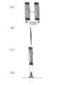
次に、前記記録媒体12に格納された三次元原画像について説明する。例えばコーンビームCT装置では、二次元の検出器を用いてローデータを取得し、そのローデータをフィルタ処理及び逆投影処理することにより画像再構成を行うため、一回の撮影により複数枚の画像(断面画像)が得られ、図2のように例えば、512×512×512ピクセルのボクセルデータを得ることができる。このボクセルデータは、図2(A)に示すように被写体の体軸方向と直交する512×512ピクセルの断面像(アキシャル画像)が512枚積み上げられた三次元原画像の画像データである。同図(B)に示すように512×512ピクセルの断面像(コロナル画像)が512枚積み上げられた三次元原画像の画像データ、又は同図(C)に示すように512×512ピクセルの断面像(サジタル画像)が512枚積み上げられた三次元原画像の画像データと考えることもできる。尚、コロナル画像及びサジタル画像はそれぞれ体軸方向と平行で互いに直交する画像である。また、この断面画像の厚さ及び再構成ピッチはそれぞれ1ピクセル当りの単位長さに相当する。
【0026】
二次元検出器にイメージングインテンシファイア(以下I.I.と称す)を用いたシステムでは、1ピクセル当りの単位長さはI.I.の視野の大きさにより変化するが、例えばI.I.の視野が16インチの場合0.49mm、6インチの場合0.18mmである。このようにコーンビームCT装置では一回の撮影で、再構成ピッチが細かく厚さの薄い断面画像(例えば0.5mm)が複数枚(例えば512枚)得られる。
【0027】
図3は図1に示した画像処理装置10の構成手段を示す図であり、表示断面方向入力手段1、断面位置入力手段2、表示厚さ入力手段3、再構成ピッチ入力手段4及び重み入力手段5は、それぞれマウス24、キーボード26等に相当し、重み付け画像処理手段6はCPU18に相当し、画像表示手段7は表示装置20に相当する。表示断面方向入力手段1、断面位置入力手段2、表示厚さ入力手段3、再構成ピッチ入力手段4及び重み入力手段5はそれぞれ表示しようとする断面画像の断面方向、位置、厚さ、再構成ピッチ及び重みを重み付け画像処理手段6に入力し、重み付け画像処理手段6はこれらの入力に基づいて前記三次元原画像を処理計算し、画像表示手段7に断面の方向、位置、厚さ、再構成ピッチ及び重み付けに対応する断面画像を表示させる。
【0028】
図4は表示装置20の表示画面28等を示す図である。表示画面28には、表示断面方向入力手段30、断面位置入力手段32、表示厚さ入力手段34、再構成ピッチ入力手段35、及び重み入力手段36及び断面画像38が表示され、各入力手段に対してはマウス24やキーボード26等の外部入力装置と連動した画面上の矢印等のポインティングデバイス40を操作して入力を行なう。
【0029】
表示断面方向入力手段30はラジオボタンでアキシャル方向、コロナル方向、サジタル方向が表示されて選択できるようになっている。また、断面位置入力手段32、表示厚さ入力手段34及び再構成ピッチ入力手段35は、それぞれスクロールバーのツマミや矢印ボタンをマウス24で操作することによって入力値を選択できるようになっている。また、重み入力手段36は入力ボックスが表示されており、入力ボックス内に重み付けする関数の形状をマウス24を用いて自由曲線を描いて決定し入力する。
【0030】
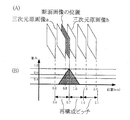
図5は断面画像の再構成ピッチ及び断面位置を説明する図である。図5(A)は三次元原画像である。図5(B)は図5(A)に示した三次元原画像の再構成ピッチを変更した場合の断面画像を示しており、図5(C)は図5(B)に示した再構成ピッチの断面画像中から選択した任意の断面位置の断面画像を示している。
【0031】
即ち、図5(A)に示すように三次元原画像は、アキシャル方向の512枚(再構成ピッチ=0.5mm)の断面画像によって構成されている。ここで、再構成ピッチを三次元原画像の4倍の2.0mmに変更すると、同図(B)に示すように128枚(=512/4)の断面画像のみが選択可能となる。
【0032】
図6は変更される再構成ピッチが三次元原画像の再構成ピッチの整数倍でない場合の断面画像の処理方法を示す図である。
【0033】
例えば、図6(B)に示すように三次元原画像の再構成ピッチが0.5mmであるのに対し、変更後の再構成ピッチを0.7mmとすると、図6(A)に示すように0.7mmの断面位置における三次元原画像は存在しない。この場合には、0.7mmの断面位置の前後の2枚の三次元原画像a,bに対して、図6(B)の重み関数を用いて0.7mmの断面位置に応じた重み付けを行い、任意の断面位置の断面画像を得る。
【0034】
即ち、表示しようとする断面画像の断面位置と、その断面位置の前後の三次元原画像a、bとの距離関係に基づいて三次元原画像a、bを補間処理して任意の断面位置の断面画像を得る。図6(B)の場合には三次元原画像aには0.6を乗算し、三次元原画像bには0.4を乗算し、これらを加算して0.7mmの断面位置における断面画像を得るようにしている。これによれば、三次元原画像の再構成ピッチよりも更に細かい再構成ピッチの断面画像を得ることもできる。
【0035】
図7は三次元原画像について断面画像の位置、断面画像の厚さ及び断面画像の重み付けを説明する図である。図7(A)は三次元原画像であり、図7(B)はアキシャル方向の任意の位置における断面像を示し、図7(C)は前記の位置から任意の厚さ分の複数枚の断面像を示し、図7(D)は前記複数枚の断面像に重み付けする関数を示している。
【0036】
図8は断面画像の方向、断面位置、断面画像の厚さの入力により選択した断面画像に対して、数パターンの重み付けする関数を示した図である。重み付けでは例えば図8(B)のような関数を与えて中心位置付近にある注目部位を強調して表示したり、図8(C)のような台形の関数を与えて図8(B)の関数よりも広い範囲の注目部位を強調する等を選択して重み付けを行なう。また、図8(D)のような矩形の関数を与えて上記パラメータに応じて選択した全ての断面画像に同一の重みを与えることもできる。また、図8(E)のようなデルタ関数を与えることにより任意の位置のみに重みを与えることもできる。
【0037】
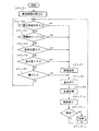
次に、上記の如く構成された画像処理装置10による画像処理方法を図9のフローチャートにより説明する。
【0038】
まず画像診断装置によって取得され、記録媒体12に記録された三次元原画像を読み込み、メモリー16に保管する(ステップ1)。
【0039】
続いて、マウス24またはキーボード26からの三次元原画像の断面画像の方向、再構成ピッチ、断面位置、表示厚さ及び重み入力を待つ(ステップ2、3、4、5、6)。
【0040】
メモリー16に保管した三次元原画像から、ステップ2〜5で入力した条件に基づいて断面画像を選択する(ステップ6)。
【0041】
前記ステップ5での表示厚さ入力に基づいて複数の断面画像が選択された場合には、前記ステップ6で入力した重み関数を乗算し、各断面画像に重み付けを行なう(ステップ8)。即ち、図8(B)に示す重み関数が入力されている場合には、断面画像群の中央の断面画像には1を乗算し、断面画像が中央から遠ざかるにしたがって0に近づく値を乗算する。また、ステップ3、4で入力した再構成ピッチと断面位置との関係で、表示しようとする断面位置の断面画像が三次元原画像中にない場合には、図6に示したようにその断面位置の前後の三次元原画像に重み付けを行う(ステップ8)。
【0042】
次に重み付けされた各断面画像を加算平均処理し、1枚の断面画像を示す画像データを作成する(ステップ9)。
【0043】
この画像データを表示装置20に出力し、断面画像を表示させる(ステップ10)。
【0044】
この断面画像を格納する指示入力があれば画像処理装置のハードディスクもしくはX線CT装置、コーンビームCT装置、MRI装置等の画像診断装置のハードディスクへ格納し(ステップ11、12)、指示入力がなければ三次元原画像の断面画像の方向、再構成ピッチ、位置、厚さ及び重みの入力待ちとなる(ステップ2、3、4、5、6)。
【0045】
図10は上述以外の断面画像の方向の入力手段を示す図である。図10(A)は入力ボックスをマウス24でクリックするとサブメニュー表示が表れ、この中から選択する方法を示した図である。図10(B)は入力ボックスの上下に配置した矢印ボタン40をマウス24でクリックすることにより表示断面方向を順番に表示して選択する方法を示した図である。
【0046】
図11は上述以外の三次元原画像の断面位置と断面画像の厚さの入力手段を示す図である。図11(A)は入力ボックスの上下に配置した矢印ボタンをマウス24でクリックすることにより断面位置や、再構成ピッチ又は表示厚さを加減表示して選択する方法を示した図である。図11(B)は断面位置入力手段及び断面画像の厚さ入力手段を一つのスクロールバーにまとめ、その値を数値で表示する等の方法を示す図である。
【0047】
図12は上述以外の重み付け入力手段を示す図である。図12(A)は入力ボックスをマウス24でクリックすると重み関数のサブメニュー表示が表れこの中から選択する方法を示した図である。図12(B)は入力ボックスの上下に配置した矢印ボタン40をマウス24でクリックすることにより重み関数が順番に表示され選択する方法を示す図である。
【0048】
また、図13のように、断面位置入力手段、断面画像の厚さ入力手段、重み付け設定手段等を全て連動して表示することもできる。断面位置を変化させた場合には断面画像の厚さ及び重み関数が平行移動する。また断面画像の厚さを変化させた場合には重み関数の幅が連動して変化する。
【0049】
尚、断面位置、再構成ピッチ、表示厚さ等の入力方法はこの実施形態に限らず種々の方法が考えられ、また、表示断面方向は前述のアキシャル、コロナル、サジタルだけでなく任意の角度(オブリーク)を選択することも可能である。
【0050】
また、この実施の形態では、再構成ピッチと表示厚さとをそれぞれ任意に変更できるようにしたが、これに限らず、再構成ピッチのみ又は表示厚さのみを任意に変更できるようにしてもよい。
【0051】
【発明の効果】
以上説明したように本発明によれば、三次元原画像から断面画像の位置や厚さに応じて複数枚の断面画像を抽出し、これらの断面画像を加算平均して1枚の断面画像を作成するようにしたため、患部の大きさや密度に応じて断面画像の断面位置、厚さ等をリアルタイムに変更することができる。また、三次元原画像から断面画像の位置や再構成ピッチに応じて断面画像を抽出するようにしたため、診断の目的に応じて断面画像の断面位置、再構成ピッチ等をリアルタイムに変更することができる。
【図面の簡単な説明】
【図1】本発明の画像処理装置の実施の形態を示す構成図
【図2】三次元原画像を説明するために用いた図
【図3】本発明の画像処理装置の構成手段を示す図
【図4】本発明の画像処理装置の表示画面の図
【図5】断面画像の再構成ピッチ及び断面位置を説明する図
【図6】変更される再構成ピッチが三次元原画像の再構成ピッチの整数倍でない場合の断面画像の処理方法を示す図
【図7】三次元原画像について断面画像の位置、断面画像の厚さ及び断面画像の重み付けを説明する図
【図8】重み関数を示す図
【図9】本発明の画像処理方法を示すフローチャート
【図10】断面画像の断面方向の入力手段を示す図
【図11】断面画像の断面位置、厚さ、再構成ピッチの入力手段を示す図
【図12】重み入力手段を示す図
【図13】断面画像の断面位置、方向、厚さ及び重みを入力する手段を示す図
【符号の説明】
1、30…表示断面方向入力手段、2、32…断面位置入力手段、3、34…表示厚さ入力手段、4、35…再構成ピッチ入力手段、5、36…重み入力手段、6…重み付け画像処理手段、7…画像表示手段、10…画像処理装置、12…記録媒体、14…インターフェース(I/F)、16…メモリー、18…CPU、20…表示装置、22…ハードディスク、24…マウス、26…キーボード、28…表示画面、38…断面画像、40…ポインティングデバイス[0001]
BACKGROUND OF THE INVENTION
The present invention relates to an image processing method and apparatus, and more particularly to an image processing method and apparatus for performing image processing for displaying a desired cross-sectional image based on a three-dimensional original image formed by stacking a plurality of cross-sectional images.
[0002]
[Prior art]
Currently, an X-ray CT apparatus, an MRI apparatus, an ultrasonic diagnostic apparatus, and the like are used as an image diagnostic apparatus. In this type of diagnostic imaging apparatus, it is important to select imaging conditions in advance in order to obtain an image suitable for diagnosis. For example, a slice surface of a subject measured by an X-ray CT apparatus actually has a thickness, not a surface, and the thickness of an X-ray fan beam that passes through the subject is generally called a slice thickness. A slice thickness of 5 to 10 mm is usually used, but a slice thickness as thin as 1 mm is used to obtain sufficient spatial resolution. Then, by changing the slice thickness, a reconstructed image that is diagnostically different can be obtained.
[0003]
The slice plane is reconstructed at an interval in the moving direction of the patient table, and this reconstruction interval is generally called a reconstruction pitch. In screening tests such as lung cancer screening, a rough reconstruction pitch of about 5 to 10 mm is usually used, and it is used for observation over a wide range from the upper lung to the lower lung. A fine reconstruction pitch of about 1 mm is used in order to require sufficient spatial resolution such as a detailed examination for knowing the state of the affected part in detail and a treatment plan or operation simulation in which grasping of the position of the affected part is important. Then, by changing the reconstruction pitch, it is possible to obtain a reconstructed image according to the diagnostic purpose.
[0004]
On the other hand, by using a cone beam CT apparatus, a multi-slice CT apparatus, or an MRI apparatus, it has become possible to take a plurality of reconstructed images with a high spatial resolution such as 0.5 mm in a short time.
[0005]
In order to obtain a cross-sectional image suitable for diagnosis, the position of the cross-section, slice thickness (hereinafter simply referred to as “thickness”), and reconstruction pitch are set in advance by the operator's experience, and the set thickness and reconstruction are performed. The thickness of the X-ray fan beam and the amount of movement of the patient table are controlled so that the pitch is the same. In addition, in an X-ray CT system, etc., any cross-sectional position and thickness can be obtained based on raw data obtained by a boule scan. And the cross-sectional image of the reconstruction pitch was reconstructed.
[0006]
Thus, it is important for diagnosis to change the position, thickness, and reconstruction pitch of the cross-sectional image according to the size and density of the affected part.
[0007]
[Problems to be solved by the invention]
By the way, in the case of changing the thickness of a cross-sectional image to be displayed, the conventional diagnostic imaging apparatus takes the raw data again by controlling the thickness of the X-ray fan beam, the amount of movement of the patient table, etc. as described above. After that, it is necessary to reconstruct a cross-sectional image based on the raw data, or to reconstruct a cross-sectional image of a desired thickness and reconstructed pitch based on the raw data obtained by a volume scan. There is a problem that the image thickness and reconstruction pitch cannot be changed in real time.
[0008]
On the other hand, it may be difficult to search for a target affected part from a large number of reconstructed images (hereinafter referred to as “cross-sectional images”) whose reconstructed pitch is fine and thin. Since the spatial resolution is high, the change between the cross-sectional images is small, it is difficult to discriminate the difference between the affected area and the normal tissue, and since the number of cross-sectional images is large, it is not easy to search for the necessary cross-sectional images. Furthermore, depending on the purpose of diagnosis, an image suitable for diagnosis can be obtained when the reconstruction pitch of the cross-sectional image is finer. On the other hand, a thicker cross-sectional image is suitable for diagnosis depending on the size and density of the affected area. Images may be obtained.
[0009]
The present invention has been made in view of such circumstances, and an image processing method capable of changing the position, thickness, or reconstruction pitch of a cross-sectional image in real time according to a diagnostic purpose based on a three-dimensional original image and An object is to provide an apparatus.
[0010]
[Means for Solving the Problems]
In order to achieve the above object, an image processing method according to
[0011]
The processes in steps (a) and (b) are a process for extracting a cross-sectional image from a three-dimensional original image and a process for adding the extracted cross-sectional images, and each is a simple process that can be processed in real time. .
[0012]
An image processing apparatus according to
[0013]
According to the image processing apparatus according to
[0014]
In the image processing apparatus according to
[0015]
According to this aspect , based on the three-dimensional original image, not only the cross-sectional position and thickness of the cross-sectional image but also the weighting is changed according to the purpose, and image processing is performed in real time so as to form a desired cross-sectional image.
[0016]
An image processing apparatus according to claim 3 of the present application intends to display an image processing apparatus that performs image processing for displaying a desired cross-sectional image based on a three-dimensional original image formed by stacking a plurality of cross-sectional images. Reconstruction pitch input means for inputting the reconstruction pitch of the sectional image, and position input for inputting the sectional position of an arbitrary sectional image on the reconstruction pitch based on the reconstruction pitch input by the reconstruction pitch input means Means and a cross-sectional image extracting means for extracting a cross-sectional image corresponding to the cross-sectional position input by the position input means from the three-dimensional original image.
[0017]
According to the image processing apparatus according to claim 3 of the present application, the reconstruction pitch is changed according to the purpose based on the three-dimensional original image, and a cross-sectional image at an arbitrary cross-sectional position on the changed reconstruction pitch can be obtained. it can.
[0018]
In the image processing apparatus according to claim 3 of the present application, the cross-sectional image extraction unit includes any one of a plurality of cross-sectional images constituting the three-dimensional original image at the cross-sectional position input by the position input unit. If not, a cross-sectional image before and after the input cross-sectional position is extracted, and the image processing apparatus determines the relationship between the extracted cross-sectional images before and after and the distance relationship between the input cross-sectional position and the front and rear cross-sectional images. A cross-sectional image creating means for creating a cross-sectional image of the input cross-sectional position based on the cross-sectional image may be further provided. That is, when the reconstruction pitch is other than an integral multiple of the pitch of the plurality of cross-sectional images constituting the three-dimensional original image, there may be no cross-sectional image on the reconstruction pitch. In this case, the cross-sectional images before and after the inputted cross-sectional position are extracted, and the cross-sectional images before and after this are interpolated to create the cross-sectional image at the inputted cross-sectional position.
[0019]
Note that both the thickness of the cross-sectional image and the reconstruction pitch may be arbitrarily changed.
[0020]
An image processing method related to the present invention is an image processing method for performing image processing for displaying a desired cross-sectional image based on a three-dimensional original image obtained by stacking a plurality of cross-sectional images. A step of inputting a reconstruction pitch of the cross-sectional image, and (b) inputting a cross-sectional position of an arbitrary cross-sectional image on the reconstruction pitch based on the reconstruction pitch of the cross-sectional image input in the step (a). And (c) extracting a cross-sectional image corresponding to the cross-sectional position input in step (b) from the three-dimensional original image, and the reconstruction pitch is changed by the step (a). Then, in step (b), it is possible to input the cross-sectional position of an arbitrary cross-sectional image on the changed reconstruction pitch and to change the reconstruction pitch of the cross-sectional image to be displayed in real time. It is characterized by.
[0021]
According to this image processing method, the reconstruction pitch can be changed according to the diagnostic purpose, and a desired cross-sectional image can be extracted from the three-dimensional original image based on the changed reconstruction pitch, in real time. The reconstruction pitch can be changed.
[0022]
DETAILED DESCRIPTION OF THE INVENTION
Hereinafter, preferred embodiments of an image processing method and apparatus according to the present invention will be described in detail with reference to the accompanying drawings.
[0023]
FIG. 1 is a block diagram showing an embodiment of an
[0024]
As shown in FIG. 1, the
[0025]
Next, the three-dimensional original image stored in the
[0026]
In a system using an imaging intensifier (hereinafter referred to as II) as a two-dimensional detector, the unit length per pixel is I.I. I. Varies depending on the size of the field of view. I. The field of view is 0.49 mm for 16 inches and 0.18 mm for 6 inches. As described above, the cone beam CT apparatus can obtain a plurality of (for example, 512) cross-sectional images (for example, 0.5 mm) with a small reconstruction pitch and a small thickness by one imaging.
[0027]
FIG. 3 is a diagram showing the constituent means of the
[0028]
FIG. 4 is a diagram showing the
[0029]
The display cross section direction input means 30 is configured to display and select an axial direction, a coronal direction, and a sagittal direction with radio buttons. The cross-section position input means 32, the display thickness input means 34, and the reconstruction pitch input means 35 can select input values by operating the knobs and arrow buttons of the scroll bar with the
[0030]
FIG. 5 is a diagram for explaining the reconstruction pitch and cross-sectional position of a cross-sectional image. FIG. 5A shows a three-dimensional original image. FIG. 5B shows a cross-sectional image when the reconstruction pitch of the three-dimensional original image shown in FIG. 5A is changed, and FIG. 5C shows the reconstruction shown in FIG. A cross-sectional image at an arbitrary cross-sectional position selected from the cross-sectional images of the pitch is shown.
[0031]
That is, as shown in FIG. 5A, the three-dimensional original image is composed of 512 cross-sectional images in the axial direction (reconstruction pitch = 0.5 mm). Here, if the reconstruction pitch is changed to 2.0 mm, which is four times the three-dimensional original image, only 128 (= 512/4) cross-sectional images can be selected as shown in FIG.
[0032]
FIG. 6 is a diagram illustrating a method of processing a cross-sectional image when the reconstructed pitch to be changed is not an integral multiple of the reconstructed pitch of the three-dimensional original image.
[0033]
For example, if the reconstruction pitch of the three-dimensional original image is 0.5 mm as shown in FIG. 6B, but the reconstruction pitch after the change is 0.7 mm, as shown in FIG. There is no three-dimensional original image at a cross-sectional position of 0.7 mm. In this case, the two three-dimensional original images a and b before and after the 0.7 mm cross-sectional position are weighted according to the cross-sectional position of 0.7 mm using the weighting function of FIG. To obtain a cross-sectional image at an arbitrary cross-sectional position.
[0034]
That is, the three-dimensional original images a and b are interpolated on the basis of the distance relationship between the cross-sectional position of the cross-sectional image to be displayed and the three-dimensional original images a and b before and after the cross-sectional position. A cross-sectional image is obtained. In the case of FIG. 6B, the three-dimensional original image a is multiplied by 0.6, the three-dimensional original image b is multiplied by 0.4, and these are added to obtain a cross-section at a cross-sectional position of 0.7 mm. I try to get an image. According to this, it is possible to obtain a cross-sectional image having a reconstruction pitch that is finer than the reconstruction pitch of the three-dimensional original image.
[0035]
FIG. 7 is a diagram illustrating the position of the cross-sectional image, the thickness of the cross-sectional image, and the weighting of the cross-sectional image for the three-dimensional original image. FIG. 7A shows a three-dimensional original image, FIG. 7B shows a cross-sectional image at an arbitrary position in the axial direction, and FIG. 7C shows a plurality of sheets of an arbitrary thickness from the above position. FIG. 7D shows a function for weighting the plurality of cross-sectional images.
[0036]
FIG. 8 is a diagram showing a weighting function of several patterns for the cross-sectional image selected by inputting the direction of the cross-sectional image, the cross-sectional position and the thickness of the cross-sectional image. In weighting, for example, a function as shown in FIG. 8B is given to highlight a region of interest near the center position, or a trapezoidal function as shown in FIG. 8C is given as shown in FIG. Weighting is performed by selecting highlighting a region of interest wider than the function. It is also possible to give a rectangular function as shown in FIG. 8D to give the same weight to all the cross-sectional images selected according to the above parameters. Further, by giving a delta function as shown in FIG. 8E, a weight can be given only to an arbitrary position.
[0037]
Next, an image processing method by the
[0038]
First, a three-dimensional original image acquired by the image diagnostic apparatus and recorded on the
[0039]
Subsequently, the input of the direction of the cross-sectional image of the three-dimensional original image, the reconstruction pitch, the cross-sectional position, the display thickness and the weight from the
[0040]
A cross-sectional image is selected from the three-dimensional original image stored in the
[0041]
When a plurality of cross-sectional images are selected based on the display thickness input in
[0042]
Next, each weighted cross-sectional image is added and averaged to generate image data representing one cross-sectional image (step 9).
[0043]
This image data is output to the
[0044]
If there is an instruction input for storing the cross-sectional image, it is stored in the hard disk of the image processing apparatus or the hard disk of the image diagnostic apparatus such as an X-ray CT apparatus, a cone beam CT apparatus, or an MRI apparatus (steps 11 and 12). For example, the input of the direction, reconstruction pitch, position, thickness and weight of the cross-sectional image of the three-dimensional original image is awaited (
[0045]
FIG. 10 is a diagram showing a means for inputting the direction of the cross-sectional image other than the above. FIG. 10A is a diagram showing a method of selecting from the submenu display when the input box is clicked with the
[0046]
FIG. 11 is a diagram showing a means for inputting the cross-sectional position of the three-dimensional original image and the thickness of the cross-sectional image other than those described above. FIG. 11A is a diagram showing a method of selecting the cross-sectional position, the reconstruction pitch, or the display thickness by clicking on the arrow buttons arranged above and below the input box with the
[0047]
FIG. 12 is a diagram showing weighting input means other than those described above. FIG. 12A is a diagram showing a method of selecting from the submenu display of the weight function when the input box is clicked with the
[0048]
Further, as shown in FIG. 13, all of the cross-sectional position input means, the cross-sectional image thickness input means, the weight setting means, and the like can be displayed in conjunction with each other. When the cross-sectional position is changed, the thickness and weight function of the cross-sectional image are translated. Further, when the thickness of the cross-sectional image is changed, the width of the weight function changes in conjunction with it.
[0049]
It should be noted that the cross-sectional position, reconstruction pitch, display thickness, and other input methods are not limited to this embodiment, and various methods are conceivable, and the display cross-sectional direction is not limited to the above-described axial, coronal, and sagittal, but may be any angle ( Oblique) can also be selected.
[0050]
In this embodiment, the reconstruction pitch and the display thickness can be arbitrarily changed. However, the present invention is not limited to this, and only the reconstruction pitch or only the display thickness may be arbitrarily changed. .
[0051]
【The invention's effect】
As described above, according to the present invention, a plurality of cross-sectional images are extracted from the three-dimensional original image according to the position and thickness of the cross-sectional image, and the cross-sectional images are averaged to obtain one cross-sectional image. Since it is created, the cross-sectional position and thickness of the cross-sectional image can be changed in real time according to the size and density of the affected area. In addition, since the cross-sectional image is extracted from the three-dimensional original image according to the position of the cross-sectional image and the reconstruction pitch, the cross-sectional position of the cross-sectional image, the reconstruction pitch, etc. can be changed in real time according to the purpose of diagnosis. it can.
[Brief description of the drawings]
FIG. 1 is a configuration diagram showing an embodiment of an image processing apparatus of the present invention. FIG. 2 is a diagram used for explaining a three-dimensional original image. FIG. 3 is a diagram showing configuration means of the image processing apparatus of the present invention. FIG. 4 is a diagram of a display screen of the image processing apparatus according to the present invention. FIG. 5 is a diagram for explaining a reconstruction pitch and a sectional position of a cross-sectional image. FIG. FIG. 7 is a diagram illustrating a method of processing a cross-sectional image when the pitch is not an integral multiple of the pitch. FIG. 7 is a diagram illustrating the position of the cross-sectional image, the thickness of the cross-sectional image, and the weight of the cross-sectional image. FIG. 9 is a flowchart showing an image processing method according to the present invention. FIG. 10 is a diagram showing input means for the cross-sectional direction of a cross-sectional image. FIG. 11 is an input means for cross-sectional position, thickness, and reconstruction pitch of the cross-sectional image. FIG. 12 is a diagram showing weight input means. FIG. 13 is a cross-sectional image. It shows cross-sectional position, direction, and means for inputting the thickness and weight EXPLANATION OF REFERENCE NUMERALS
DESCRIPTION OF
Claims (3)
表示しようとする断面画像の再構成ピッチを入力する再構成ピッチ入力手段と、
前記再構成ピッチ入力手段によって入力された再構成ピッチに基づいて該再構成ピッチ上の任意の断面画像の断面位置を入力する位置入力手段と、
前記位置入力手段によって入力された断面位置に対応する断面画像を前記三次元原画像から少なくとも2枚以上抽出する断面画像抽出手段と、
前記抽出された少なくとも2枚以上の断面画像のうち、注目部位の断面画像には1を乗算し、前記注目部位ではない断面画像には注目部位から遠ざかるに従って0に近づく値を乗算する重み付け処理を行い、重み付けされた前記断面画像を加算平均処理して1枚の断面画像を作成する手段と、
を備えたことを特徴とする画像処理装置。In an image processing apparatus that performs image processing for displaying a desired cross-sectional image based on a three-dimensional original image formed by stacking a plurality of cross-sectional images,
Reconstruction pitch input means for inputting the reconstruction pitch of the cross-sectional image to be displayed;
Position input means for inputting a cross-sectional position of an arbitrary cross-sectional image on the reconstruction pitch based on the reconstruction pitch input by the reconstruction pitch input means;
Cross-sectional image extraction means for extracting at least two cross-sectional images corresponding to the cross-sectional position input by the position input means from the three-dimensional original image;
Of the at least two extracted cross-sectional images, a weighting process is performed in which the cross-sectional image of the target region is multiplied by 1, and the cross-sectional image that is not the target region is multiplied by a value that approaches 0 as the distance from the target region increases. Performing means for averaging the weighted cross-sectional images to create one cross-sectional image;
An image processing apparatus comprising:
前記1枚の断面画像を作成する手段は、前記断面画像作成手段により作成された断面画像を含む前記2枚以上の断面画像に対して、前記重み付け処理を行う、
ことを特徴とする請求項1の画像処理装置。The cross-sectional image extraction means, when there is no cross-sectional image of any of the at least two cross-sectional images constituting the three-dimensional original image at the cross-sectional position input by the position input means, Extract cross-sectional images before and after the input cross-sectional position, and extract the cross-sectional images at the input cross-sectional position based on the extracted cross-sectional images before and after and the distance relationship between the input cross-sectional position and the cross-sectional images before and after the input. It has a section image creation means to create ,
The means for creating the single slice image performs the weighting process on the two or more slice images including the slice image created by the slice image creation means.
The image processing apparatus according to claim 1.
前記表示手段は、前記位置入力手段により入力された断面画像の断面位置が変化すると、前記厚さ入力手段と前記重み付け設定手段とを前記変化に連動して平行移動して表示し、 When the cross-sectional position of the cross-sectional image input by the position input means changes, the display means displays the thickness input means and the weight setting means by moving in parallel with the change,
前記断面画像の厚さが変化すると、前記重み付け設定手段は前記重み関数の幅を変化後の断面画像の厚さに連動させて変化させ、前記表示手段は、変化後の重み関数を表示する、 When the thickness of the cross-sectional image is changed, the weight setting unit changes the width of the weight function in conjunction with the thickness of the cross-sectional image after change, and the display unit displays the weight function after change.
ことを特徴する請求項1又は2に記載の画像処理装置。 The image processing apparatus according to claim 1, wherein:
Priority Applications (1)
| Application Number | Priority Date | Filing Date | Title |
|---|---|---|---|
| JP26911499A JP4596579B2 (en) | 1999-09-22 | 1999-09-22 | Image processing method and apparatus |
Applications Claiming Priority (1)
| Application Number | Priority Date | Filing Date | Title |
|---|---|---|---|
| JP26911499A JP4596579B2 (en) | 1999-09-22 | 1999-09-22 | Image processing method and apparatus |
Publications (3)
| Publication Number | Publication Date |
|---|---|
| JP2001087229A JP2001087229A (en) | 2001-04-03 |
| JP2001087229A5 JP2001087229A5 (en) | 2006-11-02 |
| JP4596579B2 true JP4596579B2 (en) | 2010-12-08 |
Family
ID=17467879
Family Applications (1)
| Application Number | Title | Priority Date | Filing Date |
|---|---|---|---|
| JP26911499A Expired - Fee Related JP4596579B2 (en) | 1999-09-22 | 1999-09-22 | Image processing method and apparatus |
Country Status (1)
| Country | Link |
|---|---|
| JP (1) | JP4596579B2 (en) |
Families Citing this family (16)
| Publication number | Priority date | Publication date | Assignee | Title |
|---|---|---|---|---|
| JP4597334B2 (en) * | 2000-09-12 | 2010-12-15 | 株式会社日立メディコ | Diagnostic imaging equipment |
| JP2003290172A (en) * | 2002-04-03 | 2003-10-14 | Toshiba Medical System Co Ltd | Mri unit |
| JP4559723B2 (en) * | 2003-10-31 | 2010-10-13 | 株式会社東芝 | Radiation CT apparatus, image processing apparatus, and image processing method |
| US6980624B2 (en) * | 2003-11-26 | 2005-12-27 | Ge Medical Systems Global Technology Company, Llc | Non-uniform view weighting tomosynthesis method and apparatus |
| JP4884649B2 (en) * | 2004-01-07 | 2012-02-29 | ジーイー・メディカル・システムズ・グローバル・テクノロジー・カンパニー・エルエルシー | X-ray CT system |
| JP2006034548A (en) * | 2004-07-27 | 2006-02-09 | Hitachi Medical Corp | Medical image display system |
| WO2006081362A2 (en) * | 2005-01-27 | 2006-08-03 | Aperio Technologies, Inc | Systems and methods for viewing three dimensional virtual slides |
| DE102005019369B3 (en) * | 2005-04-26 | 2006-11-16 | Siemens Ag | Device for recording cross-sectional images |
| JP4901222B2 (en) * | 2006-01-19 | 2012-03-21 | ジーイー・メディカル・システムズ・グローバル・テクノロジー・カンパニー・エルエルシー | Image display apparatus and X-ray CT apparatus |
| JP2008061957A (en) * | 2006-09-11 | 2008-03-21 | Toshiba Corp | X-ray ct device, and data processing method in x-ray ct device |
| JP5562595B2 (en) * | 2009-08-13 | 2014-07-30 | 株式会社東芝 | MEDICAL IMAGE DIAGNOSIS DEVICE AND IMAGE PROCESSING METHOD FOR MEDICAL IMAGE DIAGNOSIS DEVICE |
| JP5394218B2 (en) * | 2009-12-15 | 2014-01-22 | 富士フイルム株式会社 | MEDICAL IMAGE DISPLAY DEVICE AND METHOD, AND PROGRAM |
| JP5618230B2 (en) * | 2010-01-25 | 2014-11-05 | 学校法人日本大学 | Image generating apparatus, image generating method, and program |
| JP2012050853A (en) * | 2011-11-04 | 2012-03-15 | Toshiba Corp | X-ray ct apparatus |
| CN106463004B (en) * | 2014-06-26 | 2021-10-29 | 皇家飞利浦有限公司 | Apparatus and method for displaying image information |
| JP6746639B2 (en) * | 2018-08-02 | 2020-08-26 | ソニー株式会社 | Image processing apparatus and method, and diagnostic support system |
Family Cites Families (7)
| Publication number | Priority date | Publication date | Assignee | Title |
|---|---|---|---|---|
| JPS6110705U (en) * | 1984-06-27 | 1986-01-22 | 株式会社 日立メデイコ | CT image display device |
| JPH0234149A (en) * | 1988-07-26 | 1990-02-05 | Yokogawa Medical Syst Ltd | Method for photographing see-through image using mri |
| JPH04117945A (en) * | 1990-09-07 | 1992-04-17 | Daikin Ind Ltd | Plane tomography image interpolation display device |
| JP3301654B2 (en) * | 1993-06-28 | 2002-07-15 | 株式会社日立メディコ | Medical image processing equipment |
| JP3350208B2 (en) * | 1994-03-23 | 2002-11-25 | 東芝医用システムエンジニアリング株式会社 | Image display device |
| DE19541500A1 (en) * | 1995-11-07 | 1997-05-15 | Siemens Ag | Image generation for medical use |
| JPH09238934A (en) * | 1996-03-11 | 1997-09-16 | Toshiba Medical Eng Co Ltd | Image display system |
-
1999
- 1999-09-22 JP JP26911499A patent/JP4596579B2/en not_active Expired - Fee Related
Also Published As
| Publication number | Publication date |
|---|---|
| JP2001087229A (en) | 2001-04-03 |
Similar Documents
| Publication | Publication Date | Title |
|---|---|---|
| JP4596579B2 (en) | Image processing method and apparatus | |
| JP5400326B2 (en) | Method for displaying tomosynthesis images | |
| JP5383014B2 (en) | Radiation image processing apparatus and method | |
| JP4450797B2 (en) | Image processing method and image processing program | |
| US8571288B2 (en) | Image display apparatus and magnetic resonance imaging apparatus | |
| JP4776834B2 (en) | Image processing device | |
| JP6046111B2 (en) | MEDICAL IMAGE DISPLAY DEVICE AND MEDICAL IMAGE DISPLAY METHOD | |
| JP5976625B2 (en) | Image display apparatus and magnetic resonance imaging apparatus | |
| JP5481069B2 (en) | A reconstruction unit that reconstructs a detailed reproduction of at least part of an object | |
| CN105939671B (en) | For the ultrasonic system of more plane acquisitions using mono- or double- plane real time imagery and the method for its operation | |
| JP2007203046A (en) | Method and system for preparing image slice of object | |
| JP5367704B2 (en) | Image processing apparatus, image processing method, and image processing program | |
| EP2017789B1 (en) | Projection image generation apparatus and program | |
| CN103813752B (en) | Medical image-processing apparatus | |
| JPH0838433A (en) | Medical image diagnostic device | |
| JP4609960B2 (en) | Image processing device | |
| JP2007125374A (en) | Magnetic resonance imaging device and magnetic resonance angiography method | |
| JP6085435B2 (en) | Image processing apparatus and region of interest setting method | |
| JP4612379B2 (en) | Medical image diagnosis support system, medical image diagnosis support device, medical image diagnosis support method, computer-readable storage medium, and computer program | |
| JP2001087228A (en) | Image reading support device | |
| JP4414078B2 (en) | Image display device | |
| JP3067104B2 (en) | Image processing method and apparatus, and medical image apparatus | |
| JP2002229537A (en) | Image display device and film output image selecting device | |
| JP5426219B2 (en) | Magnetic resonance imaging system | |
| JP6777407B2 (en) | Helical CT device, medical image processing method, and medical image processing program |
Legal Events
| Date | Code | Title | Description |
|---|---|---|---|
| A521 | Request for written amendment filed |
Free format text: JAPANESE INTERMEDIATE CODE: A523 Effective date: 20060905 |
|
| A621 | Written request for application examination |
Free format text: JAPANESE INTERMEDIATE CODE: A621 Effective date: 20060905 |
|
| RD02 | Notification of acceptance of power of attorney |
Free format text: JAPANESE INTERMEDIATE CODE: A7422 Effective date: 20090716 |
|
| RD04 | Notification of resignation of power of attorney |
Free format text: JAPANESE INTERMEDIATE CODE: A7424 Effective date: 20090731 |
|
| A977 | Report on retrieval |
Free format text: JAPANESE INTERMEDIATE CODE: A971007 Effective date: 20090902 |
|
| A131 | Notification of reasons for refusal |
Free format text: JAPANESE INTERMEDIATE CODE: A131 Effective date: 20090924 |
|
| A521 | Request for written amendment filed |
Free format text: JAPANESE INTERMEDIATE CODE: A523 Effective date: 20091119 |
|
| A131 | Notification of reasons for refusal |
Free format text: JAPANESE INTERMEDIATE CODE: A131 Effective date: 20100209 |
|
| A521 | Request for written amendment filed |
Free format text: JAPANESE INTERMEDIATE CODE: A523 Effective date: 20100326 |
|
| TRDD | Decision of grant or rejection written | ||
| A01 | Written decision to grant a patent or to grant a registration (utility model) |
Free format text: JAPANESE INTERMEDIATE CODE: A01 Effective date: 20100921 |
|
| A01 | Written decision to grant a patent or to grant a registration (utility model) |
Free format text: JAPANESE INTERMEDIATE CODE: A01 |
|
| A61 | First payment of annual fees (during grant procedure) |
Free format text: JAPANESE INTERMEDIATE CODE: A61 Effective date: 20100921 |
|
| R150 | Certificate of patent or registration of utility model |
Free format text: JAPANESE INTERMEDIATE CODE: R150 |
|
| FPAY | Renewal fee payment (event date is renewal date of database) |
Free format text: PAYMENT UNTIL: 20131001 Year of fee payment: 3 |
|
| LAPS | Cancellation because of no payment of annual fees |