JP4594482B2 - Magnetic resonance imaging method and magnetic resonance imaging apparatus - Google Patents
Magnetic resonance imaging method and magnetic resonance imaging apparatus Download PDFInfo
- Publication number
- JP4594482B2 JP4594482B2 JP2000070639A JP2000070639A JP4594482B2 JP 4594482 B2 JP4594482 B2 JP 4594482B2 JP 2000070639 A JP2000070639 A JP 2000070639A JP 2000070639 A JP2000070639 A JP 2000070639A JP 4594482 B2 JP4594482 B2 JP 4594482B2
- Authority
- JP
- Japan
- Prior art keywords
- magnetic resonance
- resonance imaging
- images
- imaging apparatus
- projection images
- Prior art date
- Legal status (The legal status is an assumption and is not a legal conclusion. Google has not performed a legal analysis and makes no representation as to the accuracy of the status listed.)
- Expired - Lifetime
Links
Images


Description
【0001】
【発明の属する技術分野】
この発明は、医用の磁気共鳴イメージングにおいて高周波の選択励起用インバージョン(反転回復:IR)パルスを用いて被検体の血管像やCSF(脳脊髄液)をイメージングするイメージング法に係り、とくに、造影剤を投与しないが、あたかも造影剤を投与したかの如く、血流やCSFの動態を擬似的に表示することができる、非造影磁気共鳴イメージングに関する。
【0002】
【従来の技術】
磁気共鳴イメージングは、静磁場中に置かれた被検体の原子核スピンをラーモア周波数の高周波信号で磁気的に励起し、この励起に伴って発生するFID(自由誘導減衰)信号やエコー信号から画像を得る手法である。
【0003】
この磁気共鳴イメージングの一つのカテゴリーとして、血液の動態を画像化するMRアンギオグラフィ(MRA)が注目されている。
【0004】
このMRAでは、一般には、MRIにおける信号強度を大きく変化させる性質を有する造影剤を血管内が投与され、同一条件のスキャンを連続して行ない、血流の移動の様子を画像化する、造影ダイナミックMRアンギオグラフィ(以下、CE−DMRA:contrast enhanced dynamic MRAと呼ばれる)が採用されている(例えば、「M.Prince,Radiology 1994;191:144−164」。
【0005】
このCE−DMRAの撮像手順の概念的に図12に示す。まず、造影剤を静脈に注入し、撮像領域に在る血管に造影剤が到達する時期から連続的にスキャンを行なう。同図(a)の曲線CBは、撮像対象内の1点の位置における信号強度の時間変化を示す。同図(b)に示す如く、造影剤注入時刻t0から造影剤の到達点が撮像領域を横切り、全ての血管が描出されるのは、部位や撮像領域の大きさにも依り、一概には定義できないが、およそ30秒から2分程度である。同図(b)の期間PD1、PD2、…は、第1番目、第2番目、…のスキャン期間を表している。また、このスキャン期間PD1、PD2、…では所望の、例えば3次元パルスシーケンスが実行され、この実行に応じて発生するエコー信号が収集される。エコー信号は、そのスキャン毎に再構成して、同図(c)に概念的に表す如く、例えば3次元画像データD1、D2、…に生成される。この画像データD1、D2、…は、例えばある視点からみたときの最大値を投影する処理(最大値投影処理)に付され、同図(d)に概念的に表す如く、最大値投影像IMmax1、IMmax2、…に処理され、表示される。
【0006】
このCE−DMRAで使用されるスキャン法は、主に、FE(フィールドエコー)法に基づくパルスシーケンスである。この一例を図13に示す。同図に示す如く、高調波励起パルスPextがスライス選択励起傾斜磁場Gsselと共に印加され、エコー信号Sechoがリード方向傾斜磁場Grの印加と共に受信される。図中、傾斜磁場Gsrewはスライス方向のリワインド傾斜磁場を示す。この一連の励起及び収集は、位相エンコード傾斜磁場Geの例えば強度を変更しながら、画像再構成に必要なエコーデータが揃うまで所定回数、繰返し時間TR毎に繰り返される。繰返し時間TRは通常、3−10ms程度である。
【0007】
なお、図13は2次元フーリエ法に基づく画像再構成に必要なパルスシーケンスで説明しているが、撮像目的によっては、3次元フーリエ法に基づく画像再構成であってもよい。その場合、各励起の繰返しにより位相エンコード傾斜磁場Geの強度を変化させて一連のデータが収集されると、今度はスライス方向のリワインド傾斜磁場Gsrewの強度を変化させる。そして、再び位相エンコード傾斜磁場Geの強度変化に伴う一連のデータを収集する、という操作が、スライス方向のマトリクス数分、実行される。これにより、3次元フーリエ法に拠る画像再構成に必要な全データが収集される。
【0008】
このようにCE−DMRAにおいて、再構成された時系列に沿った画像D1、D2、…、又は、その画像を最大値投影した画像IMmax1、IMmax2、…を時系列に表示・観察することで、血管BVを流れる血液BDの動的な挙動を把握することができる。この手法は、撮像対象において動きのある対象物、例えば撮像対象が人体のときには、CSF(脳脊髄液)などの撮像に適用可能で、同様な処理を経てその挙動を観察可能である。なお、CSFを撮像対象とするときには、ハイドログラフィ(hydrography)と呼ばれる。
【0009】
一方、造影剤を投与しないで、インバージョン(IR)パルスにより局所的に動きのあるスピンに標識を付け、血管像を得る従来法が、論文「“Considerations of Magnetic Resonace Angiography by Selective Inversion Recovery”, D.G.Nishimura et al., Magnetic Resonance in Medicine, Vol.7,472−484,1988」で提案されている。この従来法に係るアンギオグラフィの概要を図14に示す。同図(a)はECG(心電図)同期法を併用するときのパルスシーケンスを、同図(b)は撮像対象の各部におけるスピンの縦磁化の時間変化の様子を、同図(c)は撮像断面と標識付け用(タグ用)インバージョンパルスPinv−Aで励起される領域RGAとの位置関係を示す。
【0010】
同図(a)に示す如く、ECG信号のR波から一定の時間経過後(但し、同図ではR波の直後に記載)に、フリップ角が180度のインバージョンパルスPinv−Aが印加される。このとき、関心のある血管の撮像断面CSへの流入元と思われる領域RGAが選択的に励起されるように、インバージョンパルスPinv−AのRF周波数がその中心周波数からオフセット量Dfだけシフトされ、このインバージョンパルスPinv−Aと共に選択励起傾斜磁場Geが印加される。インバージョンパルスPinv−Aが印加された後、300〜1000ms程度の一定時間を置いた後、エコー信号を収集するためのパルスシーケンスPseqが実行される。このシーケンスは例えばSE(スピンエコー)法で構成される。この一連の操作が1画面の再構成に必要な全てのエコーデータが収集できるまで繰り返される。エコーデータは再構成処理されて、血管像に生成される。このアンギオグラフィに使用可能なパルスシーケンスは、SE法に限らず、セグメント分割されたFE法であってもよい。このセグメンティドFE法は、一例として、論文「Fast Angiography Using SelectiveInversion Recovery“, Samuel J.Wang et al., Magnetic Resonance in Medicine, Vol.23,109−121,1992」で提案されている。
【0011】
なお、”D.G.Nishimura et al.“の論文には、インバージョンパルスPinv−Aで励起される一部領域RGAの位置や幅を変更した複数の画像を収集し、それぞれの画像から差画像を作成する手法が述べられている。この差分演算により、血管以外の部分の信号を抑制し、血管の描出能を上げる、というものである。
【0012】
さらに、造影剤を使用しないアンギオグラフィの他の例として、図15(a)〜(c)に説明する手法も知られている。同図の手法は、前述した図14に示す手法と、論文「D.Chien et al.,“High Speed black blood imaging of vessel stenosisin the presence of pulsatile flow”,J.Magn.Reson.Imaging, Vol.2(4),437−441,1992」、又は、「Simonetti O.P. et al.,Radiology,199,49,1996」に記載の手法とを組合せたものである。エコー信号を得るためのスキャン用パルスシーケンスPseqとしては、例えば高速SE(FSE)法が用いられる。この図15記載の手法は、図14記載のものと同様であるが、インバージョンパルスの印加の点で異なる。つまり、撮像したい断面CS全体を励起するインバージョンパルスPinv−Aを最初に選択的に印加し、この直後(例えば2〜10ms後)に、図14と同様に関心血管の流入元と思われる一部領域RGAが選択励起されるように2番目のインバージョンパルスPinv−Bが印加される。この第1番目及び第2番目のインバージョンパルスPinv−A及びPinv−Bの間の時間は、血流速度に比して極めて短いので、血管の原子核スピンからみた場合、ほぼ同じと見なすことができる。したがって、関心血管の原子核スピンは極めて短時間の内に、180度パルスの印加を2回受けるので、同図(b)に示すように、縦磁化はほぼ初期状態に戻された状態で一部領域RGAから撮像断面CSに流れ出るから、組織よりも高信号の部分として描出される。なお、前述した図14の手法が、血管の信号は組織のそれよりも低い値として画像化されることと対称を成す。
【0013】
【発明が解決しようとする課題】
しかしながら、上述した造影剤を用いた従来のCE−DMRA法の場合、造影剤は1回の検査中に1回(或は2回程度)しか注入できないため、注入された造影剤に拠り信号強度が変化している30秒から2分程度の限られた時間内に全てのスキャンを完了させなければならない。原則として、十分な時間分解能を確保するには、1回のスキャン時間はなるべく短くする必要がある。その一方で、画像のS/Nはスキャン時間の平方根に比例するので、スキャン時間を短くすればするほど、S/Nは低下する。このため、従来法に拠れば、スキャンの時間分解能と空間分解能とはトレードオフの関係にあり、両者を共に飛躍的に高くすることはできない。
【0014】
一方、前述した造影剤を投与しないMRアンギオグラフィの場合、前述した図14又は図15記載のパルスシーケンスの実行を通して得た複数の血管像の差分を演算し、背景となる血管以外の部分の信号を抑制することは述べられている。これにより、血管の描出能を上げることはできるが、血流の動態をダイナミックに捉える表示や観察の手法は提示されていない。血流の場合には、その描出能もさることながら、経時的にどのような挙動をとるかについての情報も極めて重要である。
【0015】
本発明は、上述した従来技術が抱える状況に鑑みてなされたもので、従来法のスキャンに因る時間分解能と空間分解能とのトレードオフの関係を打破し、造影剤を投与することなく、時間分解能と空間分解能を共に非常に高いレベルまで引き上げた画像を提供することを、1つの目的とする。
【0016】
また、造影剤を投与することなく、時間分解能と空間分解能を共に非常に高いレベルまで引き上げ、かつ、動く対象物の動態観察を可能にする画像を提供することを、別の目的とする。
【0017】
【課題を解決するための手段】
本発明の原理は、被検体の撮像したい領域の少なくとも一部の領域に局所的に高周波のインバージョン(IR)パルスを印加し、その少なくとも一部の領域内に在るスピンの縦磁化を反転励起することでタグ(標識)付けする(ラベリングとも呼ばれる)。その一部領域の内、タグ付けされた静止部のスピンはそのままの位置に留まるが、動きのある対象物としての例えば血液のタグ付けされたスピンは、その後も血管に沿って流れ続ける。スキャンとしては、上述のインバージョンパルスを印加した後、一定時間が経過すると、撮像領域に対して所望のパルスシーケンスに拠るスキャンが開始され、エコー信号が収集される。このエコー信号に基づき撮像領域の画像を得る。この画像には、タグ付けされたまま撮像領域まで流れ出た血液などの信号がその他の部位とは異なるコントラストで反映されるので、血液などの動態情報を提供することができる。
【0018】
以下の発明の構成で説明するように、一例として、タグ付けを行なってからエコー信号を収集するまでの時間、或は、タグ付けを行なう一部領域の位置を撮像領域にて徐々に変更しながら、エコー信号が収集され、画像に生成される。かかる時間や位置の変更に対応して生成された複数枚の画像を順に観察することで、血液などの動きのある対象物の動態を擬似的に把握することができる。
【0019】
具体的な構成として、本発明に係る磁気共鳴イメージング方法は、磁気共鳴イメージング装置の制御手段が当該装置の各部を制御することで、被検体の撮像領域の少なくとも一部の領域のスピンを反転させるタグ付けを行なうために選択励起傾斜磁場と共にタグ付けインバージョンパルスを発信し、この後、一定時間が経過した後にパルスシーケンスを開始して前記スピンのエコー信号を受信し、このエコー信号から前記撮像領域内の動きのある撮像対象を画像化する方法であり、前記一部の領域の空間位置を変更して前記選択励起傾斜磁場及び前記タグ付けインバージョンパルスを複数回発信し、この発信の度に前記一定時間が経過してから前記パルスシーケンスを実行すると共に、発信の度に行われる前記パルスシーケンスに応答してそれぞれ発生する前記エコー信号に基づいて複数の画像を生成し、前記複数の画像を投影処理して複数の投影画像を作成し、前記複数の投影画像を動的に表示することを特徴とする。
【0020】
例えば、前記タグ付けを行なうための処理としては、前記撮像領域全体に印加するための別のインバージョンパルスを最初に発信し、その直後に前記タグ付けインバージョンパルスを発信する工程を含む。
【0021】
また、好適には、前記複数の投影画像を所定の順に連続的に表示することができる。例えば、前記複数の投影画像は、前記一部の領域の空間位置の変更順に応じて連続的に表示される。
【0022】
さらに例えば、前記複数の投影画像を同時に表示することで、前記複数の投影画像を動的に表示することができる。
【0023】
さらに、一例として、前記複数の画像に対して、前記一部の領域に対応する画像上の位置を求めて当該位置にマスキング処理を施し、このマスキング処理後における前記複数の画像から一定値の画素を投影することで、前記複数の投影画像を作成してもよい。この場合、例えば、前記複数の投影画像が所定の順に連続表示される。
【0024】
さらに、好適には、前記一定値の画素を投影する処理は、画素値の最大値又は最小値を投影する処理である。
【0025】
さらに、別の例として、前記複数の投影画像のそれぞれにおける、前記一部の領域により2分割される分割領域の内の一方のみを連続的に表示するようにしてもよい。
【0026】
さらに、別の例として、前記複数の投影画像を作成するために、前記複数の画像それぞれにおける、前記一部の領域により2分割される分割領域の内の一方のみにマスキング処理を施すこともできる。このとき、好適には、前記マスキング処理が施されて生成された前記複数の投影画像を連続的に表示するようにする。また、前記マスキング処理を施した前記複数の画像のそれぞれの少なくとも一部から一定値の画素を投影した前記複数の投影画像を作成し、これらの投影画像を表示するようにしてもよい。例えば、前記マスキング処理は、前記撮像対象の動きの方向の上流側の分割領域に施される。
【0027】
さらに、別の例として、前記タグ付けインバージョンパルスは、前記撮像対象の動きに比較して同時と見なすことができる微小時間毎に連続して発信する複数のインバージョンパルスから成り、これにより、各回の前記パルスシーケンス毎に、前記少なくとも一部の領域が複数設定される。このときの好適な一例として、前記複数のインバージョンパルスの発信条件、及び、前記複数のインバージョンパルスと同時に発信する前記選択励起傾斜磁場の発信条件は、前記少なくとも一部の領域が前記撮像領域上に空間的に一定間隔で並び、且つ、各回の前記パルスシーケンス毎に相互にずれた位置になるように設定される。
【0032】
一方、本発明に係る磁気共鳴イメージング装置は、被検体の撮像領域の少なくとも一部の領域のスピンを反転させるタグ付けを行うために、選択励起傾斜磁場と共にタグ付けインバージョンパルスを発信後、一定時間が経過した後にパルスシーケンスを開始して前記スピンのエコー信号を受信し、このエコー信号に基づいて前記撮像領域内の動きのある撮像対象を画像化する磁気共鳴イメージング装置において、前記一部の領域の空間位置を変更して前記選択励起傾斜磁場及び前記タグ付けインバージョンパルスを複数回発信する手段と、前記発信の都度、前記一定時間の経過後に前記パルスシーケンスを実行する手段と、前記発信の都度に行われる前記パルスシーケンスに応答してそれぞれ発生するエコー信号に基づいて複数の画像を生成する手段と、前記複数の画像を投影処理して複数の投影画像を作成する手段と、前記複数の投影画像を動的に表示する手段とを備えたことを特徴とする。
【0033】
本発明のその他の態様に係る具体的な構成及び特徴は、以下に記す発明の実施形態及び添付図面により明らかにされる。
【0034】
【発明の実施の形態】
以下、本発明の実施の形態を添付図面に基づき説明する。
【0035】
(第1の実施形態)
第1の実施形態に係るMRI(磁気共鳴イメージング)装置を、図1〜3を参照して説明する。
【0036】
このMRI装置は、特徴的には、造影剤を使用することなく、被検体内の動く対象物としての例えば血流の動態を表す擬似的なダイナミック画像を例えばシネモード画像として提示する非造影MRアンギオグラフィ(MRA)を実行する機能を有する。この非造影MRAを行なうパルスシーケンスには、選択励起の高調波反転回復(IR)パルスを用いる。
【0037】
このMRI装置の概略構成を図1に示す。この装置構成は、後述する各実施形態で共通に使用可能なものである。
【0038】
このMRI装置は、被検体としての患者Pを載せる寝台部と、静磁場を発生させる静磁場発生部と、静磁場に位置情報を付加するための傾斜磁場発生部と、高周波信号を送受信する送受信部と、システム全体のコントロール及び画像再構成を担う制御・演算部と、被検体Pの心時相を表す信号としてのECG信号を計測する心電計測部と、患者Pに息止めを指令するための息止め指令部とを備えている。
【0039】
静磁場発生部は、例えば超電導方式の磁石1と、この磁石1に電流を供給する静磁場電源2とを備え、被検体Pが遊挿される円筒状の開口部(診断用空間)の軸方向(Z軸方向)に静磁場H0 を発生させる。なお、この磁石部にはシムコイル14が設けられている。このシムコイル14には、後述するホスト計算機の制御下で、シムコイル電源15から静磁場均一化のための電流が供給される。寝台部は、被検体Pを載せた天板を磁石1の開口部に退避可能に挿入できる。
【0040】
傾斜磁場発生部は、磁石1に組み込まれた傾斜磁場コイルユニット3を備える。この傾斜磁場コイルユニット3は、互いに直交するX、Y及びZ軸方向の傾斜磁場を発生させるための3組(種類)のx,y,zコイル3x〜3zを備える。傾斜磁場部はまた、x,y,zコイル3x〜3zに電流を供給する傾斜磁場電源4を備える。この傾斜磁場電源4は、後述するシーケンサ5の制御のもと、x,y,zコイル3x〜3zに傾斜磁場を発生させるためのパルス電流を供給する。
【0041】
傾斜磁場電源4からx,y,zコイル3x〜3zに供給されるパルス電流を制御することにより、物理軸である3軸X,Y,Z方向の傾斜磁場を合成して、互いに直交するスライス方向傾斜磁場Gs、位相エンコード方向傾斜磁場Ge、および読出し方向(周波数エンコード方向)傾斜磁場Grの各論理軸方向を任意に設定・変更することができる。スライス方向、位相エンコード方向、および読出し方向の各傾斜磁場は、静磁場H0に重畳される。
【0042】
送受信部は、磁石1内の撮影空間にて被検体Pの近傍に配設されるRFコイル7と、このコイル7に接続された送信器8T及び受信器8Rとを備える。この送信器8T及び受信器8Rは、後述するシーケンサ5の制御のもとで動作する。送信器8Tは、核磁気共鳴(NMR)を起こさせるためのラーモア周波数のRF電流パルスをRFコイル7に供給する。受信器8Rは、RFコイル7が受信したエコー信号(高周波信号)を取り込み、これに前置増幅、中間周波変換、位相検波、低周波増幅、フィルタリングなどの各種の信号処理を施した後、A/D変換してエコー信号に応じたデジタル量のエコーデータ(原データ)を生成する。
【0043】
さらに、制御・演算部は、シーケンサ(シーケンスコントローラとも呼ばれる)5、ホスト計算機6、演算ユニット10、記憶ユニット11、表示器12、入力器13、および音声発生器16を備える。この内、ホスト計算機6は、記憶したソフトウエア手順により、シーケンサ5にパルスシーケンス情報を指令するとともに、装置全体の動作を統括する機能を有する。
【0044】
ホスト計算機6は、位置決め用スキャンなどの準備作業に引き続いて、図2に示すパルスシーケンスに基づいてイメージングスキャンを実施する。このイメージングスキャンは、画像再構成に必要なエコーデータの組を収集するスキャンであり、ここでは2次元スキャンに設定されている。イメージングスキャンは、ECG信号に依るECGゲート法を併用して行われる。なお、このECGゲート法は場合によっては併用しなくてもよい。
【0045】
このパルスシーケンスとしては、3次元(3D)スキャンまたは2次元(2D)スキャン)である。そのパルス列の形態としては、SE(スピンエコー)法、FSE(高速SE)法、FASE(高速 Asymmetric SE)法(すなわち、高速SE法にハーフフーリエ法を組み合わせたイメージング法)、EPI(エコープラナーイメージング)法、などが用いられる。
【0046】
シーケンサ5は、CPUおよびメモリを備えており、ホスト計算機6から送られてきたパルスシーケンス情報を記憶し、この情報にしたがって傾斜磁場電源4、送信器8T、受信器8Rの動作を制御するとともに、受信器8Rが出力したエコーデータを一旦入力し、これを演算ユニット10に転送するように構成されている。ここで、パルスシーケンス情報とは、一連のパルスシーケンスにしたがって傾斜磁場電源4、送信器8Tおよび受信器8Rを動作させるために必要な全ての情報であり、例えばx,y,zコイル3x〜3zに印加するパルス電流の強度、印加時間、印加タイミングなどに関する情報を含む。
【0047】
また、演算ユニット10は、受信器8Rが出力したエコーデータ(原データ又は生データ)をシーケンサ5を通して入力し、その内部メモリ上のフーリエ空間(k空間または周波数空間とも呼ばれる)にエコーデータを配置し、このエコーデータを各組毎に2次元又は3次元のフーリエ変換に付して実空間の画像データに再構成する。また演算ユニットは、必要に応じて、画像に関するデータの合成処理、差分演算処理などを行うことができる。
【0048】
この合成処理には、2次元の複数フレームの画像データを対応する画素毎に加算する加算処理、3次元データに対して視線方向の最大値又は最小値を選択する最大値投影(MIP)又は最小値(MIP)投影処理などが含まれる。また、合成処理の別の例として、フーリエ空間上で複数フレームの軸の整合をとってエコーデータのまま1フレームのエコーデータに合成するようにしてもよい。なお、加算処理には、単純加算処理、加算平均処理、重み付け加算処理などが含まれる。
【0049】
記憶ユニット11は、再構成された画像データのみならず、上述の合成処理や差分処理が施された画像データを保管することができる。表示器12は画像を表示する。また入力器13を介して、術者が希望する撮影条件、パルスシーケンス、画像合成や差分演算に関する情報をホスト計算機6に入力できる。
【0050】
また、息止め指令部の一要素として音声発生器16を備える。この音声発生器16は、ホスト計算機6から指令があったときに、息止め開始及び息止め終了のメッセージを音声として発することができる。
【0051】
さらに、心電計測部は、被検体の体表に付着させてECG信号を電気信号として検出するECGセンサ17と、このセンサ信号にデジタル化処理を含む各種の処理を施してホスト計算機6およびシーケンサ5に出力するECGユニット18とを備える。この心電計測部による計測信号は、イメージングスキャンを実行するときにシーケンサ5により用いられる。これにより、ECGゲート法(心電同期法)による同期タイミングを適切に設定でき、この同期タイミングに基づくECGゲート法のイメージングスキャンを行ってデータ収集できるようになっている。
【0052】
次に、図2〜3を参照して、本実施形態に係るMRI装置の動作を説明する。
【0053】
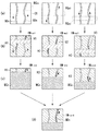
図2には、本実施形態に係る非造影MRアンギオグラフィで用いるパルスシーケンスを、図3には、スキャンから表示画像生成までの処理過程を説明する図を示す。なお、理解を容易にするため、この実施形態で行なう非造影MRアンギオグラフィは、3回の2次元スキャンを行なって、連続する3枚の最終的な画像を得て、これらをシネ表示するものとする。
【0054】
また、実際の画像では信号値が低い画素ほど暗く表示されるが、図2(b)〜(d)では高信号に描出される部分ほど濃いハッチングで表し、低信号の描出領域は薄いハウジングで表すものとする。
【0055】
最初にパルスシーケンスを説明する。図2(a)〜(c)に示すパルスシーケンスは、非常に短い時間(2〜10ms)の間に2つのインバージョンパルスを印加する前述した図15の手法に基づくパルス列である。具体的には、ECG信号のR波に同期して(R波に対する遅延時間は任意)1回目のインバージョンパルスPinv−Aが撮像したい領域CS(図3(a)参照)を含むように非選択的に印加される。
【0056】
この後、血流速度から見た場合、同時であると見なすことができる、極めて短い時間が経過した後で、2回目のインバージョンパルスPinv−Bが選択励起傾斜磁場Geと共に印加される。この後、予め定めた一定のTI時間(例えば600ms)が経過すると、例えばFSE法に拠るパルスシーケンスに基づくイメージングスキャンが撮像領域CSに対して実行される。
【0057】
なお、図2(a)〜(c)の各パルスシーケンスは、2回目のインバージョンパルスPinv−Bに拠る選択励起位置、すなわち撮像領域CSに対するタグ領域RGA(スピン反転領域)の空間的位置を変えるように構成されている点が相互に異なっている。具体的には、インバージョンパルスPinv−Bの搬送周波数のオフセット量Dfが互いに変更されている。
【0058】
そこで、2回目のインバージョンパルスPinv−Bによって選択的に励起されるタグ領域RGA(:RGA1〜RGA3)は、選択励起傾斜磁場Geと周波数オフセット量Dfの調整によって、最初には、図3(a)左欄の点線で如く、撮像対象である患者(被検体)における、撮像する領域CS(例えば断面)に流入する血液BDの上流部分に設定される。
【0059】
撮像時には、ホスト計算機6は、かかるタグ領域RGAの設定位置の情報を含むパルシーケンス情報をシーケンサ5に送る。これに応答し、シーケンサ5は、与えられたパルスシーケンス情報にしたがって、傾斜磁場電源4及び送信器8Tを駆動する。これにより、図2(a)のパルスシーケンスのパルス列を構成するパルスが時系列に印加される。
【0060】
これにより、前述の図15で説明した如く、最初のインバージョンパルスPinv−Aにより撮像領域CS全体のスピンが180度、反転される。しかし、その後直ぐに印加される2回目のインバージョンパルスPinv−Bにより、選択されたタグ領域RGAのスピンのみが再び180度反転(タグ付け)されて、ほぼ初期状態に戻される(図15(b)参照)。このスピンのフリップ角の戻り、すなわちタグ付けに拠り、前述の図15(c)に模式的に示す如く、両方のインバージョンパルスPinv−A及びPinv−Bで励起された部分の血液のエコー信号が一番、高強度に発生する。
【0061】
この血液からのエコー信号を含む全体のエコー信号は、RFコイル7を介して受信器8Rで受信され、エコーデータとしてシーケンサ5を介して演算ユニット10に送られる。
【0062】
演算ユニット10は、このエコーデータを適宜な処理に付して2次元k空間に配置する。このk空間全部がエコーデータで埋まると、演算ユニット10は、そのエコーデータを2次元フーリエ変換し、図3(b)左欄に示す如くの2次元の再構成画像IMrec1を得る。
【0063】
この再構成画像IMrec1から分かるように、2回目のインバージョンパルスPinv−Bを印加するときにタグ領域RGA内にあった血液BDは、その磁化スピンが殆ど初期状態に戻されていることから、撮像領域CS上において、2回目のインバージョンパルスPinv−Bを印加した後、イメージング用のパルスシーケンスPseqを印加するまでの間にタグ領域から流れ出た分だけ部分的に高信号に描出される。また、タグ領域RGAのうち、背景となる動きの無い組織の部分は、2回目のインバージョンパルスPinv−Bを受けて殆ど初期状態のスピンになっているので、最初のインバージョンパルスPinv−Aが印加されただけの動きの無い部分とは異なるコントラストで描出される。
【0064】
この再構成が終わると、演算ユニット10により、再構成画像IMrec1の内、コントラストが異なる部分についてマスキング処理が実行される。同図中、クロスハッチング部分MG1はマスキング領域を示す。マスキング処理は、画像上のある範囲の画像値をある一定の画素値に書き換える処理である。マスキング処理により、図3(c)左欄のように表される中間画像IMint1が得られる。
【0065】
上述した第1回目のスキャンと同様にして第2回目及び第3回目のスキャンも行なわれる。そして、それらのスキャンにより得たエコー信号も同様に処理されて、図3(c)の真中欄及び右欄に示す如く、マスキング処理を行った中間画像中間画像IMint2及びIMint3が得られる。
【0066】
ただし、第2回目及び第3回目のスキャンの場合には、2回目に選択的に印加するインバージョンパルスPinv−Bの印加位置は図3(a)〜(c)の真中欄及び右欄に示す如く、血液の流れ方向に沿って少しずつ移動させるように、選択励起傾斜磁場Ge及びインバージョンパルスPinv−Bの搬送周波数(高周波)のオフセット量が変更されて、前述したパルスシーケンスが実行される。
【0067】
なお、演算ユニット10において実行される画像再構成及びマスキング処理による中間画像の生成の処理のタイミングは任意でよい。
【0068】
このようにして中間画像IMint1,IMint2,IMint3が得られと、演算ユニット10は、この画像を適宜に組み合わせて最大値投影処理を実行し、複数枚の最終画像IMfin1,IMfin2,IMfin3が生成される。この最大値投影処理の際、最初の中間画像IMint1については、そのままマスキング領域を外して1番目の最終画像IMfin1として再記憶し、1番目及び2番目の中間画像IMint1,IMint2については、それら画像間の対応する2つの画素を相互に比較して大きい方を採ることで2番目の最終画像IMfin2が生成され、さらに、1番目、2番目、及び3番目の中間画像IMint1,IMint2,IMint3については、それらの対応する3画素を互いに比較して最大値を採ることで3番目の採集画像IMfin3が生成される。
【0069】
この3枚の最終画像IMfin1,IMfin2,IMfin3は、表示器12によって、シネモードの元に連続的に動画表示される。これにより、関心領域に流入する血液の流入状況(動態)をダイナミックに観察し、把握することができる。
【0070】
とくに、血液の動態が時間的により短い場合でも同様のダイナミック観察を行うことができる。この場合、全体のスキャン時間は長くなるが、インバージョンパルスPinv−Bを印加するタグ領域RGAの空間的位置の移動量を小さくして、より多くの画像を収集すればよい。さらに、各画像の空間分解能を更に向上させたい場合、インバージョンパルスPinv−Bを印加するタグ領域RGAの空間的位置を変えずに、繰り返してスキャンすればよい。これにより、マトリクス数の多い、すなわち空間分解能が高い画像を得ることができる。さらに、S/Nの高い画像を得たい場合も同様に、インバージョンパルスPinv−Bを印加する空間的位置を変えずにスキャンを繰り返し、加算回数の多いスキャンを行なえばよい。
【0071】
つまり、前述した従来のCE−DMRAの場合(図12参照)、造影剤に因って関心領域にて信号変化が起こる時間は一定であるため、スキャンの繰返し数などの撮像条件を変更すると、時間分解能が低下するという問題があったが、本実施形態によれば、インバージョンパルスによる反転励起を繰返し実行可能であるため、従来のような制約は無い。したがって、許される時間内で、空間分解能、時間分解能を自由に変更でき、かつ、その両方を共に向上させることができる。
【0072】
この実施形態は、以下のように種々の変形が可能である。
【0073】
例えば、上述のダイナミック表示法の他の例として、表示器12に3枚の最終画像IMfin1,IMfin2,IMfin3を単純に同時表示させ、読影者が目視によりそれらの画像を相互に比較するようにしてもよい。これにより、目視による血行動態の観察が可能になる。
【0074】
また、本実施形態は血液を画像化するMRAについて説明したが、撮像対象としてその他の動きのある対象物、例えばCSFなどについても同様に画像化できる。このCSFの場合、インバージョンパルスの印加からイメージングスキャンまでの時間幅を適宜変更すればよい。
【0075】
また、図2に示すパルスシーケンスにおいて、必要に応じて、2回目のインバージョンパルスPinv−BとイメージングスキャンPseqとの間にて、撮像する断面に在る脂肪からの信号を抑える脂肪抑制パルスを印加するようにしてもよい。
【0076】
さらに、本実施形態は、前述した図15の手法と同様にインバージョンパルスを2つ用いる手法に基づく実施形態を説明したが、これに代えて、前述した図14に示すように、インバージョンパルスを1つだけ用いる手法に基づいて上述の実施形態を行なってもよい。この場合の後処理は、前述の最大値投影処理に代えて、最小値投影処理を行なえばよい。
【0077】
また、本実施形態で使用可能なパルスシーケンスは、上述したようにFSE法を使用する例に限らず、FE法、セグメンティドFE法、SE法、エコープラナー法などの各種の手法を採用できる。さらに、データ収集及び画像再構成についても、上述した2次元スキャン及び2次元再構成に限定されるものでは無く、それらを3次元で行なってもよい。
【0078】
さらに、上述した実施形態では、中間画像IMint1〜IMint3から最大値投影処理を行なって最終画像IMfin1〜IMfin3を生成するようにしたが、これについても各種の変形が可能である。例えば、最大値投影処理を実行しないで、複数枚の中間画像をシネモードで順に表示させるだけであっても、血流の動態を観察することができる。また、中間画像を作成するためのマスキング処理を省いてもよい。
【0079】
(第2の実施形態)
第2の実施形態に係るMRI装置を、図4,5を参照して説明する。なお、これ以降の実施形態において、前述した第1の実施形態におけるのと同一又は同等の構成要素には同一符号を付して、その説明を省略又は簡略化する。
【0080】
この実施形態のMRI装置は、前述の図15記載の手法に基づくMRAを実施するものであるが、とくに、インバージョンパルスの印加からスキャンまで、すなわちイメージング用のスキャンを実行するまでの時間内に血液が移動する距離よりも広い範囲の血管像又は血流動態を表すシネ画像を収集することに特徴を有する。
【0081】
このMRI装置のハードウエア的な構成は第1の実施形態のものと同一である。
【0082】
図4には、本実施形態に係る非造影MRアンギオグラフィ撮像で用いるパルスシーケンスを、図5には、スキャンから表示画像生成までの処理過程を説明する図を示す。この実施形態で行なう非造影MRアンギオグラフィは、3回の2次元スキャンを行なって、1枚の広い範囲の最終的な血管像を得ものとする。
【0083】
なお、図5(b)〜(d)では画素値の大小をハッチングの濃さで表しており、高信号に描出される部分ほど濃いハッチングで表している。
【0084】
最初にパルスシーケンスを説明する。図4(a)〜(c)に示すパルスシーケンスは、非常に短い時間(2〜10ms)の間隔で4つのインバージョンパルスを印加する。具体的には、ECG信号のR波に同期して(R波に対する遅延時間は任意)1回目のインバージョンパルスPinv−Aが撮像したい領域CS(図5(a)参照)を含むように非選択的に印加される。この後、血流速度から見た場合、同時であると見なすことができる、極めて短い時間間隔で、2回目〜4回目のインバージョンパルスPinv−B〜Pinv−Dが順次、選択励起傾斜磁場Geと共に印加される。このインバージョンパルスPinv−B〜Pinv−Dの印加位置は、図5(a)左欄に示す如く、撮像領域CSに流入する血液の上流部分から下流方向に向かって一定間隔で並ぶように、選択励起傾斜磁場Geとそれらのパルスの周波数のオフセット量Dfが設定されている。このタグ領域間の血流走行方向における空間間隔は、第1の実施形態の場合とは異なり、インバージョンパルスが印加されてからスキャンが開始されるまでの間に血液が進む距離よりもやや長くなるように設定されている。なお、インバージョンパルス間の時間間隔は非常に短いので、これらの4個のインバージョンパルスは血流から見て同時と見なすことができる。
【0085】
この一連のインバージョンパルスの印加の後、予め定めた一定のTI時間(例えば600ms)が経過すると、例えばFSE法に拠るパルスシーケンスに基づくイメージングスキャンが撮像領域CSに対して実行される。
【0086】
なお、図4(a)〜(c)の各パルスシーケンスにおいて、周波数のオフセット量Dfがシーケンス毎に調整されている。これにより、2回目〜4回目のインバージョンパルスPinv−B〜Pinv−Dに拠る3個の選択励起位置、すなわち撮像領域CSに対するタグ領域RGA〜RGCの空間的位置が図5(a)〜(c)の左欄、真中欄、右欄に示す如く、互いに変更されている。
【0087】
撮像が開始されると、第1の実施形態と同様に、シーケンサ5により、与えられたパルスシーケンス情報にしたがって図4(a)のパルスシーケンスが実行される。これにより、前述の如く、最初のインバージョンパルスPinv−A及び2回目〜4回目のインバージョンパルスPinv−B〜Pinv−Dの何れかで励起された部分の血液のエコー信号が一番、高強度に発生する。このエコー信号はエコーデータとして演算ユニット10に送られる。演算ユニット10は、このエコーデータを適宜な処理に付して2次元k空間に配置し、このデータを2次元フーリエ変換する。これにより、図5(b)左欄に示す如くの2次元の再構成画像IMrec1を得る。
【0088】
この再構成画像IMrec1から分かるように、2回目〜4回目のインバージョンパルスPinv−B〜Pinv−Dを印加するときにタグ領域RGA〜RGC内にあった血液BDは、その磁化スピンが殆ど初期状態に戻されていることから、撮像領域CS上において、2回目〜4回目のインバージョンパルスPinv−B〜Pinv−Dを印加した後、イメージング用のパルスシーケンスPseqを印加するまでの間にタグ領域から流れ出た分だけ部分的に高信号に描出される。また、タグ領域RGA〜RGCのうち、背景の動きの無い組織の部分は、2回目〜4回目のインバージョンパルスPinv−B〜Pinv−Dの何れかを受けて殆ど初期状態のスピンになっているので、最初のインバージョンパルスPinv−Aが印加されただけの動きの無い部分とは異なるコントラストで描出される。
【0089】
この再構成が終わると、演算ユニット10により、再構成画像IMrec1の内、コントラストが異なる部分についてマスキング処理が実行される。同図中、クロスハッチング部分MG11〜MG21はマスキング領域を示す。このマスキング処理により、図5(c)左欄のように表される中間画像IMint1が得られる。
【0090】
上述した第1回目のスキャンと同様にして第2回目及び第3回目のスキャンも行なわれる。そして、それらのスキャンにより得たエコー信号も同様に処理されて、図5(c)の真中欄及び右欄に示す如く、マスキング処理を行った中間画像中間画像IMint2及びIMint3が得られる。
【0091】
ただし、第2回目及び第3回目のスキャンの場合には、2回目〜4回目に選択的に印加するインバージョンパルスPinv−B〜Pinv−Dの印加位置は図5(a)〜(c)の真中欄及び右欄に示す如く、血液の流れ方向に沿って少しずつ下流に移動させるように、選択励起傾斜磁場Ge及びインバージョンパルスPinv−B〜Pinv−Dの周波数オフセット量Dfが変更されて、前述したパルスシーケンスが実行される。
【0092】
なお、演算ユニット10において実行される画像再構成及びマスキング処理による中間画像の生成の処理のタイミングは任意でよい。
【0093】
このように得られた中間画像IMint1,IMint2,IMint3は、演算ユニット10により、最大値投影処理に付され、1枚の最終画像IMfinが生成される。この最終画像IMfinは表示器12によって表示される。これにより、関心領域に流入する血液の流入状況(動態)を観察することができる。
【0094】
このように、複数回行う各回のスキャンにおいて、2回目〜4回目のインバージョンパルスの印加時に複数のタグ領域RGA〜RGCに在った血液の移動分を同時に検出して、インバージョンパルス印加からスキャンまでの間に血流が移動する距離以上に広い範囲の血管像が得られる。これにより、1回のスキャンで設定する複数個のタグ領域の数(つまり2回目以降のインバージョンの印加数)、その幅(選択励起幅)、全体のスキャン回数などの条件を適宜に選択することにより、血流速度が遅い場合でも、少ないスキャン回数で、血流の全走行路を網羅した広い領域にわたって精細な血管像を提供することができる。
【0095】
この実施形態は、以下の変形も可能である。
【0096】
上述した実施形態において得られた複数の中間画像IMint1〜IMint3から、マスキング処理を施していない残りの部分の画像R1〜R9を切り出し、例えばこの順に表示してもよい。
【0097】
また、前述した図3(d)に示した如く、最大値投影処理に付す元画像(ここでは中間画像)を増やしながら、複数枚の最大値投影画像を作成し、それらを適宜な順番に表示するようにしてもよい。これにより、擬似的に血流動態のダイナミック画像を提供することができ、血流の挙動の把握が容易化される。
【0098】
さらに、本実施形態は血液を画像化するMRAについて説明したが、撮像対象としてその他の動きのある対象物、例えばCSFなどについても同様に画像化できる。このCSFの場合、インバージョンパルスの印加からイメージングスキャンまでの時間幅を適宜に変更すればよい。
【0099】
また、図4に示すパルスシーケンスにおいて、必要に応じて、4回目のインバージョンパルスPinv−DとイメージングスキャンPseqとの間で脂肪抑制パルスを印加するようにしてもよい。
【0100】
さらに、本実施形態は、前述した図15の手法に基づく実施形態を説明したが、これに代えて、前述した図14に示す手法に基づいて上述の実施形態を行なってもよい。この場合は、前述の最大値投影処理に代えて、最小値投影処理を行なえばよい。
【0101】
一方、本実施形態では、イメージング用のパルスシーケンスは、FE法、セグメンティドFE法、SE法、エコープラナー法などの各種の手法を採用できる。さらに、データ収集及び画像再構成は3次元で行なってもよい。
【0102】
(第3の実施形態)
次に、本発明の第3の実施形態を図6〜8に基づき説明する。この実施形態に係るMRI装置は、流れの方向を分離して表す血管像を表示する機能に特徴を有する。
【0103】
図6は、このMRAで使用するパルスシーケンスを、図7は、紙面上方に流れる血流(例えば静脈BDV)を描出する手法を、さらに、図8は、紙面下方に流れる血流(例えば動脈BDA)を描出する手法を夫々示す。
【0104】
図6に示すパルスシーケンスは、2回目に印加するインバージョンパルスPinv−Bの周波数オフセット量Dfの設定を除いて、前述した図2のものと同様に設定される。すなわち、一例としての合計3回のスキャンにおいて印加される2回目のインバージョンパルスPinv−Bのオフセット量Dfは+極性の所定値、零、及び−極性の所定値に設定される。これにより、この3回のスキャンによって選択的に励起されるタグ領域RGA1〜RGA3の空間的位置は、図7(a)及び図8(a)に示す如く、撮像領域CS上で血流の流れ方向において対称的に上部、中間、及び下部の所定部位に位置し、且つ、相互に所定距離ずつ離して設定される。
【0105】
いま、図7,8に示す如く、左右1本ずつ上下方向にて相互に反対向きに流れている2本の血管を含む撮像部位CSの動静脈分離をしたMR像を得るものとする。
【0106】
最初に、静脈BDVを画像化する場合を図6,7に基づき説明する。図6(a)〜(c)に示すパルスシーケンスがそれぞれ実行される。これにより、図7(a)の左欄、中央欄、右に示す如く、2回目のインバージョンパルスPinv−Bに拠る選択励起によって、血流走行方向に等距離ずつ離れ且つ対称な位置に在るタグ領域RGA1〜RGA3が励起される(タグ付けされる)、この選択励起を反映したエコー信号がそれぞれ収集される。
【0107】
このエコー信号は、前述と同様に、デジタル量のエコーデータに処理され、演算ユニット10により再構成される。この再構成画像を図7(b)の画像IMrec1,IMrec2,IMrec3として示す。
【0108】
この再構成画像IMrec1,IMrec2,IMrec3から分かるように、2回目のインバージョンパルスPinv−Bを印加するときにタグ領域RGA1〜RGA3内にあった動脈BDA及び静脈BDVは、その磁化スピンが殆ど初期状態に戻されていることから、撮像領域CS上において、2回目のインバージョンパルスPinv−Bを印加した後、イメージング用のパルスシーケンスPseqを印加するまでの間にそのタグ領域から流れ出た分(符号A1〜A3及びV1〜V3参照)だけ部分的に高信号に描出される。このとき流れ出る距離は、動脈及び静脈の流速に応じて差が生じる。
【0109】
また、タグ領域RGA1〜RGA3のうち、背景の動きの無い組織の部分は、2回目のインバージョンパルスPinv−Bを受けて殆ど初期状態のスピンになっているので、最初のインバージョンパルスPinv−Aが印加されただけの動きの無い部分とは異なるコントラストで描出される。
【0110】
この再構成が終わると、演算ユニット10により、再構成画像IMrec1,IMrec2,IMrec3の内、背景のコントラストが異なる部分についてマスキング処理が実行される。すなわち、図7(c)に示す如く、撮像領域CSを二分するタグ領域RGA1〜RGA3のそれぞれを境にして、この各タグ領域RGA1(〜RGA3)を含む静脈上流側の部分がそれぞれマスキングされる。同図中、クロスハッチング部分MG1〜MG3はマスキング領域を示す。このマスキング処理により、図7(c)左欄、中央欄、右欄のように表される中間画像IMint1〜IMint3が得られる。
【0111】
このように得られた中間画像IMint1,IMint2,IMint3は、演算ユニット10により、最大値投影処理に付され、1枚の最終画像IMfin−Vが図7(d)に示す如く生成される。この最終画像IMfin−Vは表示器12によって表示される。これにより、関心領域を流れる静脈BDVのMRA像を得ることができる。
【0112】
一方、動脈BDAを画像化する場合を図6,8に基づき説明する。このときも図6(a)〜(c)に示すパルスシーケンスがそれぞれ実行される。これにより、静脈BDVのときと同様に、再構成画像画IMrec1,IMrec2,IMrec3が得られ(図8(b))、次いでマスキング処理に付される。この場合のマスキング処理は、静脈の場合とは反対に、図8(c)に示す如く、撮像領域CSを二分するタグ領域RGA1〜RGA3のそれぞれを境にして、この各タグ領域RGA1(〜RGA3)を含む動脈上流側の部分がそれぞれマスキングされる。
【0113】
これにより作成された中間画像IMint1,IMint2,IMint3は次いで最大値投影処理に付され、動脈BDAのみが現われたMRA像を表示することができる。
【0114】
このように本実施形態によれば、エコー信号収集後の後処理において、マスキング処理の位置を変えるだけの簡単な方法により、動静脈を分離したMRA像を簡単に提供することができる。また、このMRA像を利用して、単純に、動静脈の走行方向を調べることもできる。
【0115】
なお、この実施形態にあっても、マスキングされてできた残りの動静脈別の画像R1,R2,R3を順に連続表示してもよいし、再構成画像IMrec1,IMrec2,IMrec3を順に連続表示してもよい。これにより、動静脈の擬似的なダイナミック画像を観察することができる。
【0116】
(第4の実施形態)
次に、本発明の第4の実施形態を図9,10に基づき説明する。この実施形態に係るMRI装置は、イメージングスキャン(本スキャン)を行うときにパルスシーケンスに用いるインバージョン(IR)より選択的に励起する厚さ(スライス厚又はスラブ厚)を最適値に設定するためのスキャン(プリスキャン)に関する。
【0117】
前述した第2の実施形態に係る図4,5、又は、前述した図14,14に係るMRアンギオグラフィを実施するときに、撮像する断面や動態を観察しようとする血管に応じて血流の流入速度が変わることから、インバージョンパルスによって高信号化する部分の距離が短かったり、反対に長過ぎて別のインバージョンで励起されたタグ領域に高信号部分が残ったりして、画像合成やシネ画像表示に適さない場合もあり得る。本実施形態では、このような事態を確実に排除することができるプリスキャンの手法を教示する。
【0118】
このプリスキャンでは、インバージョンパルスによる励起厚さを段階的に変えながら連続的にスキャンを行って、最適な励起厚さ及び励起位置が求められる。
【0119】
図9には、このプリスキャンに使用するパルスシーケンスの例を、図10には、プリスキャンの手順を模式的に示す。
【0120】
図9(a)〜(c)は、1回目〜3回目までの3回のスキャンに用いるパルスシーケンスをそれぞれ表している。これらのパルスシーケンスにおいて、スキャンの度に、2回目のインバージョンパルスPinv−Bの搬送周波数のオフセット量Df及び選択励起傾斜磁場Geの強度の内、少なくとも一方が調整されている。これにより、図10(a)の左欄、中央欄、及び右欄に示す如く、撮像する領域CSに対して設定するタグ領域RGA(RGA1〜RGA3)の厚さが徐々に厚くなるとともに、1回目〜3回目の何れのスキャンであっても、帯状のタグ領域RGA1〜RGA3の血流下流側における境界位置が同じになるように位置選択される。つまり、スキャン回数が増えるにつれて、タグ領域RGA1〜RGA3の血流上流側における境界位置のみが変化して厚くなるように励起位置が設定されている。図9(a)〜(c)のパルスシーケンスにおいて、その他のパルス列は前述したもとの同等である。
【0121】
なお、このプリスキャンにおけるスキャンの回数、血流上流側の境界位置の変動幅などの条件は、撮像部位の血流速度とかかる変化幅の所望値とを含む条件を考慮して決定される。
【0122】
プリスキャンとして、これらのパルスシーケンスを順次実行することにより、図10(a)〜(c)に示す如く、シーケンス毎に再構成画像IMrec1〜IMrec3が得られる。
【0123】
そこで、例えば、操作者は、この一連の画像IMrec1〜IMrec3を目視観察して、目的とする撮像部位に最適と思われる、インバージョンパルスによる励起厚さ及び空間位置を決定する。このとき、かかる決定を容易にするため、一連の画像IMrec1〜IMrec3をタグ領域の厚さの順に連続表示するようにしてもよい。なお、上述の決定は、操作者のよる人為的判断に拠る手法のほか、血流の輪活抽出法など、適宜なアルゴリズムを用いて自動的に行うようにしてもよい。
【0124】
以上のプリスキャンにより得られた励起厚さ及び空間位置の情報は、本スキャンのパルスシーケンスにおいて印加される2回目のインバージョンパルスPin v−Bの搬送周波数及びこれと同時に印加される選択励起傾斜磁場の例えば強度に反映される。この結果、本スキャンにより得られるMRA像において、インバージョンパルスPinv−Bによりタグ付けされた血流部分の撮像長さと血流速度との関係が適正になり、的確な画像合成やシネ画像表示を行うことができる。
【0125】
なお、上述の実施形態は血液を画像化するMRAについて説明したが、撮像対象としてその他の動きのある対象物、例えばCSFなどについても同様に画像化できる。このCSFの場合、タグ付け用インバージョンパルスの印加からイメージングスキャンまでの時間幅を適宜に変更すればよい。
【0126】
また、図9に示すパルスシーケンスにおいて、必要に応じて、2回目のインバージョンパルスPinv−BとイメージングスキャンPseqとの間で脂肪抑制パルスを印加するようにしてもよい。
【0127】
さらに、本実施形態は、前述した図15の手法に基づく実施形態を説明したが、これに代えて、前述した図14に示す手法に基づいて上述の実施形態を行なってもよい。この場合は、前述の最大値投影処理に代えて、最小値投影処理を後処理として行なえばよい。
【0128】
一方、本実施形態では、イメージング用パルスシーケンスは、FSE法に限らず、FE法、セグメンティドFE法、SE法、エコープラナー法などの各種の手法を採用できる。さらに、データ収集及び画像再構成は3次元で行なってもよい。
【0129】
(第5の実施形態)
本発明の第5の実施形態に係るMRI装置を説明する。この実施形態は、選択励起に拠るタグ付け領域の別の例に関する。
【0130】
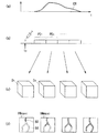
図11(a)には、このMRI装置で使用するパルスシーケンスの一例を示し、同図(b)には、再構成画像の一例を示す。
【0131】
このパルスシーケンスに拠れば、インバージョンパルスは1個のパルスPinv−Oのみを用いる。このパルスの搬送周波数と選択励起傾斜磁場Geは、インバージョンパルスPinv−Oにより励起される領域RGAは図11(b)に示す如く、撮像する領域CSと同じになるように設定される。つまり、このインバージョンパルスPinv−Oはスピンを180度、反転させてタグ付けする機能を有するが、このタグ付けは、スキャン時に流入する新しい血流による高信号に対してコントラストを付けるため、領域RGAのスピンを低信号化させる逆タグ付けの機能になる。図11(a)に示す如く、インバージョンパルスは、かかるタグ付けのパルスPinv−Oのみが単独で印加される。その他のパルス列は前述した各実施形態のものと同じである。
【0132】
このパルスシーケンスを実行してエコー信号が収集され、このエコー信号から図11(b)に例示する再構成画像IMrecが得られる。
【0133】
したがって、インバージョンパルスPinv−Oにより撮像領域CSと同じ領域RGAが逆タグ付けされ、その後、反転時間TIの後に、スキャンが実行される。
【0134】
このため、スキャン時には、インバージョンパルスPinv−Oにより選択励起されなかった領域から、例えば動脈BDA及び静脈BDVが飽和されていないスピンとして撮像領域CSに流入する。したがって、動脈BDA及び静脈BDVから高信号を得て、それらを確実に描出することができる。
【0135】
とくに、動静脈では流速に速度差があるので、スキャン時に撮像領域CSに流入する部分の長さは異なるのが通常である。このため、例えば静脈BDVの流入長さL分だけ、撮像領域CSよりも静脈上流側に入り込んだ領域を選択励起するように設定することで、動脈BDAのみを表示した画像を提示することができる。
【0136】
なお、以上説明してきた全部の実施形態に共通の変形例として、同期法の手法がある。つまり、前述の各実施形態は心電同期法を前提としたMRイメージングを説明してきたが、この同期法に代えて、脳波同期法、呼吸同期法などを用いてもよい。また、同じ心電同期法であっても、脈波同期法(PPG)を用いることもできる。
【0137】
さらに、前述した各実施形態では、タグ付け用インバージョンパルスによる励起位置を変更することによって血液やCSFの動態を表示する手法を教示してきたが、同期法で使用するトリガの発生から一連のインバージョンパルスの印加までの時間幅(遅延時間)を適宜に変更しながらスキャンを行うようにしてもよい。これにより得られた画像を適宜な順に表示したり、複数の最大値投影画像を作成し表示したりすることにより、心拍や呼吸に同期した撮像対象の周期的な動きを観察することができる。
【0138】
更に、上述した各実施形態は種々の形態に展開できる。第1に、タグ付けインバージョンパルスの印加に伴って画像化される血流部分の転置は、血流の流速に応じて異なるので、この対応関係に基づき血流の流速を測定することができる。
【0139】
第2に、タグ付けインバージョンパルスの搬送周波数のオフセット量と選択励起傾斜磁場の強度を適宜に可変することで、タグ領域を任意のスライス位置(スラブ位置)、スライス厚(スラブ厚)、又はオブリーク励起位置に設定することができる。
【0140】
第3に、タグ付けインバージョンパルスによるスライス厚(スラブ厚)を可変することで、任意のスライス厚(スラブ厚)の血管を描出することができる。
【0141】
第4に、タグ付けインバージョンパルスのフリップ角の好適な一例は180度であるが、このフリップ角は必ずしもこれに限定されない。この角度を180度未満の適宜な値に設定することで、より短いTI時間で、信号低下させた領域の信号を収集して、スキャン時間全体を短縮させることができる。
【0142】
なお、本発明は、代表的に例示した上述の実施形態及び変形形態に限定されるものではなく、当業者であれば、特許請求の範囲の記載内容に基づき、その要旨を逸脱しない範囲内で種々の態様に変形、変更することができ、それらも本発明の権利範囲に属するものである。
【0143】
【発明の効果】
以上説明したように、本発明のMRイメージングによれば、従来のMRAで問題となっていた、時間分解能と空間分解能との両立が図られ、共に高いレベルに保持でき、血液やCSFのような流体の動態に関する詳細な情報を得ることができる。
【0144】
さらに、本発明のMRイメージングの手法では、従来のCE−DMRAで必須であった造影剤の投与が不要になるので、非侵襲となり、被検者の精神的、物理的な負担を著しく軽減することができる。また、造影剤投与時のような撮像タイミングの認識に伴う煩わしさも不要で、検査の準備や手間が大幅に軽減される。
しかも、造影剤を使用していないので、検査のやり直しにも容易に対応できる。
【0145】
さらに、本発明によるMRイメージングの手法によれば、インバージョンパルスによってタグ付けする領域の位置は自在に設定できるため、流入血管を限定して検査することもでき、精度及び確実性の高い検査が可能になる。
【図面の簡単な説明】
【図1】本発明の実施形態に係るMRI装置の概略構成を示すブロック図。
【図2】第1の実施形態で使用する、タグ用インバージョンパルスが1個であるパルスシーケンス。
【図3】第1の実施形態における撮像領域とタグ領域の位置関係及びMRA像の生成手順を説明する図。
【図4】第2の実施形態で使用する、複数のタグ用インバージョンパルスを有するパルスシーケンス。
【図5】第2の実施形態における撮像領域とタグ領域の位置関係及びMRA像の生成手順を説明する図。
【図6】第3の実施形態で使用するパルスシーケンス。
【図7】第3の実施形態における動静脈分離に関する、撮像領域とタグ領域の位置関係及びMRA像の生成手順を説明する図。
【図8】第3の実施形態における動静脈分離に関する、撮像領域とタグ領域の位置関係及びMRA像の生成手順を説明する図。
【図9】第4の実施形態に係るプリスキャンで使用する、タグ用インバージョンパルスが1個であるパルスシーケンス。
【図10】第4の実施形態に係るプリンスキャンにおける、撮像領域とタグ領域の位置関係及びMRA像の生成手順を説明する図。
【図11】第5の実施形態に係るパルスシーケンス及び画像例を示す図。
【図12】従来技術としてのCE−DMRAを説明する図。
【図13】CE−DMRAに用いるパルスシーケンスの例示する図。
【図14】従来のMRAの一例をパルスシーケンスと共に説明する図。
【図15】従来のMRAの別の一例をパルスシーケンスと共に説明する図。
【符号の説明】
1 磁石
2 静磁場電源
3 傾斜磁場コイルユニット
4 傾斜磁場電源
5 シーケンサ
6 ホスト計算機
7 RFコイル
8T 送信器
8R 受信器
10 演算ユニット
11 記憶ユニット
12 表示器
13 入力器[0001]
BACKGROUND OF THE INVENTION
The present invention relates to an imaging method for imaging a blood vessel image or CSF (cerebrospinal fluid) of a subject using an inversion (inversion recovery: IR) pulse for selective excitation of high frequency in medical magnetic resonance imaging, and in particular, contrast enhancement. The present invention relates to non-contrast-enhanced magnetic resonance imaging in which blood flow and CSF dynamics can be displayed in a pseudo manner as if a contrast agent was administered, although no agent was administered.
[0002]
[Prior art]
In magnetic resonance imaging, the nuclear spin of a subject placed in a static magnetic field is magnetically excited with a high-frequency signal of Larmor frequency, and an image is generated from an FID (free induction decay) signal or echo signal generated by this excitation. It is a technique to obtain.
[0003]
As one category of this magnetic resonance imaging, MR angiography (MRA) for imaging blood dynamics has attracted attention.
[0004]
In this MRA, in general, a contrast medium having the property of greatly changing the signal intensity in MRI is administered inside the blood vessel, scanning under the same conditions is continuously performed, and the movement of blood flow is imaged. MR angiography (hereinafter referred to as “CE-DMRA”) is employed (for example, “M. Prince, Radiology 1994; 191: 144-164”).
[0005]
This CE-DMRA imaging procedure is conceptually shown in FIG. First, a contrast medium is injected into a vein, and scanning is continuously performed from the time when the contrast medium reaches a blood vessel in the imaging region. A curve CB in FIG. 5A shows a time change of the signal intensity at the position of one point in the imaging target. As shown in FIG. 6B, the arrival point of the contrast agent crosses the imaging region from the contrast agent injection time t0, and all blood vessels are drawn depending on the size of the region and the imaging region. Although it cannot be defined, it is about 30 seconds to 2 minutes. In FIG. 7B, periods PD1, PD2,... Represent first, second,. In the scan periods PD1, PD2,..., A desired, for example, three-dimensional pulse sequence is executed, and echo signals generated in response to the execution are collected. The echo signal is reconstructed for each scan and is conceptually shown in FIG.As shown inFor example, it is generated into three-dimensional image data D1, D2,. This image data D1, D2,... Is attached to, for example, a process of projecting the maximum value when viewed from a certain viewpoint (maximum value projection process), and is conceptually shown in FIG.As shown in, Maximum value projection images IMmax1, IMmax2,... Are processed and displayed.
[0006]
The scan method used in the CE-DMRA is a pulse sequence mainly based on the FE (field echo) method. An example of this is shown in FIG. As shown in the figure, the harmonic excitation pulse PextIs slice selective excitation gradient magnetic field GsselApplied with the echo signal SechoAre received together with the application of the read direction gradient magnetic field Gr. In the figure, gradient magnetic field GsrewIndicates a rewind gradient magnetic field in the slice direction. This series of excitation and acquisition is repeated a predetermined number of times for each repetition time TR until echo data necessary for image reconstruction is completed while changing, for example, the intensity of the phase encoding gradient magnetic field Ge. The repetition time TR is usually about 3-10 ms.
[0007]
Note that FIG. 13 illustrates the pulse sequence necessary for image reconstruction based on the two-dimensional Fourier method, but image reconstruction based on the three-dimensional Fourier method may be used depending on the imaging purpose. In that case, when a series of data is collected by changing the intensity of the phase encoding gradient magnetic field Ge by repeating each excitation, this time the rewind gradient magnetic field Gs in the slice direction is collected.rewVary the intensity. Then, the operation of collecting a series of data associated with the intensity change of the phase encoding gradient magnetic field Ge is performed again for the number of matrices in the slice direction. As a result, all data necessary for image reconstruction based on the three-dimensional Fourier method is collected.
[0008]
Thus, in CE-DMRA, the image D along the reconstructed time series1, D2, ..., or an image IM obtained by projecting the maximum valuemax1, IMmax2,... Are displayed and observed in time series to grasp the dynamic behavior of the blood BD flowing through the blood vessel BV. This method can be applied to imaging of a moving object in the imaging target, for example, a CSF (cerebrospinal fluid) when the imaging target is a human body, and the behavior can be observed through similar processing. In addition, when CSF is taken as an imaging target, it is called hydrography.
[0009]
On the other hand, a conventional method for labeling a spin that is locally moved by an inversion (IR) pulse and obtaining a blood vessel image without administration of a contrast agent is described in the paper “Considations of Magnetic Resonance by Selective Inversion Recovery”, DG Nishimura et al., Magnetic Resonance in Medicine, Vol. 7, 472-484, 1988 ". An outline of the angiography according to this conventional method is shown in FIG. FIG. 6A shows a pulse sequence when the ECG (electrocardiogram) synchronization method is used together, FIG. 6B shows a time change state of longitudinal magnetization of spins in each part to be imaged, and FIG.Section and labelingInversion pulse P for (tag)inv-AExcited region RGAThe positional relationship is shown.
[0010]
As shown in FIG. 5A, after an elapse of a certain time from the R wave of the ECG signal (however, shown immediately after the R wave in the same figure), the inversion pulse P having a flip angle of 180 degrees.inv-AIs applied. At this time, a region RG that seems to be an inflow source to the imaging section CS of the blood vessel of interestAInversion pulse P so that is selectively excitedinv-AThe RF frequency of the inversion pulse P is shifted from the center frequency by the offset amount Df.inv-AAt the same time, a selective excitation gradient magnetic field Ge is applied. Inversion pulse Pinv-APulse sequence P for collecting echo signals after a certain time of about 300 to 1000 ms is applied.seqIs executed. This sequence is constituted by, for example, the SE (spin echo) method. This series of operations is repeated until all echo data necessary for reconstruction of one screen can be collected. The echo data is reconstructed and generated into a blood vessel image. The pulse sequence that can be used for this angiography is not limited to the SE method, but may be a segmented FE method. As an example, this segmented FE method is described in the paper “Fast Angiography Using Selective Inversion Recovery”, Samuel J. et al. Wang et al. , Magnetic Resonance in Medicine, Vol. 23, 109-121, 1992 ".
[0011]
In addition, the paper “DG Nishimura et al.” Includes an inversion pulse Pinv-ARegion RG excited byAA method is described in which a plurality of images with different positions and widths are collected and a difference image is created from each image. By this difference calculation, signals other than the blood vessel are suppressed, and the blood vessel rendering ability is improved.
[0012]
Further, as another example of angiography that does not use a contrast agent, a technique described in FIGS. 15A to 15C is also known. 14 and the paper “D. Chien et al.,“ High Speed black blood imaging of vessellensis the presence of pulsatile flow ”, J. Ming. 2 (4), 437-441, 1992 "or" Simonetti OP, et al., Radiology, 199, 49, 1996 ". Scanning pulse sequence P to obtain an echo signalseqFor example, a fast SE (FSE) method is used. The method shown in FIG. 15 is the same as that shown in FIG. 14, but differs in the application of an inversion pulse. That is, the inversion pulse P that excites the entire cross section CS to be imaged.inv-AIs selectively applied first, and immediately after this (for example, after 2 to 10 ms), as in FIG.ASecond inversion pulse P so that is selectively excitedinv-BIs applied. The first and second inversion pulses Pinv-AAnd Pinv-BSince the time between is extremely short compared to the blood flow velocity, it can be regarded as almost the same when viewed from the nuclear spin of the blood vessel. Therefore, since the nuclear spin of the blood vessel of interest receives the application of the 180-degree pulse twice within a very short time, as shown in FIG. 5B, the longitudinal magnetization is partially returned to the initial state. Region RGASince it flows out from the imaging section CS to the imaging section CS, it is rendered as a portion having a higher signal than the tissue. Note that the above-described method of FIG. 14 is symmetric to that the blood vessel signal is imaged as a value lower than that of the tissue.
[0013]
[Problems to be solved by the invention]
However, in the case of the conventional CE-DMRA method using the above-described contrast agent, since the contrast agent can be injected only once (or twice) during one examination, the signal intensity depends on the injected contrast agent. All scans must be completed within a limited time of 30 seconds to 2 minutes, where the change is. In principle, in order to ensure a sufficient time resolution, it is necessary to shorten a scan time as much as possible. On the other hand, since the S / N of the image is proportional to the square root of the scanning time, the shorter the scanning time, the lower the S / N. For this reason, according to the conventional method, the temporal resolution and the spatial resolution of the scan are in a trade-off relationship, and both cannot be increased dramatically.
[0014]
On the other hand, in the case of MR angiography without administration of the contrast agent, the difference between a plurality of blood vessel images obtained through the execution of the pulse sequence shown in FIG. 14 or FIG. Suppressing is stated. Thereby, the ability to depict blood vessels can be improved, but no display or observation technique for dynamically capturing the dynamics of blood flow has been presented. In the case of blood flow, in addition to its ability to depict, information on how it behaves over time is extremely important.
[0015]
The present invention has been made in view of the situation of the above-described conventional technology, and breaks the trade-off relationship between the temporal resolution and the spatial resolution due to the scanning of the conventional method. One object is to provide an image in which both resolution and spatial resolution are raised to a very high level.
[0016]
Another object of the present invention is to provide an image that allows both temporal and spatial resolutions to be very high without administering a contrast agent and enables dynamic observation of a moving object.
[0017]
[Means for Solving the Problems]
The principle of the present invention is that a high-frequency inversion (IR) pulse is locally applied to at least a part of a region to be imaged of a subject, and the longitudinal magnetization of spins in the at least part of the region is reversed. Tag (label) by excitation (also called labeling). Of the partial area, the tagged spin of the stationary part remains in the same position, but the tagged spin of blood as a moving object continues to flow along the blood vessel thereafter. As a scan, after a certain time has elapsed after applying the above-described inversion pulse, a scan based on a desired pulse sequence is started with respect to the imaging region, and an echo signal is collected. An image of the imaging region is obtained based on this echo signal. In this image, a signal such as blood flowing out to the imaging region while being tagged is reflected with a contrast different from that of other parts, so that dynamic information such as blood can be provided.
[0018]
As described in the configuration of the invention below, as an example, the time from tagging to collecting echo signals or the position of a partial area for tagging is gradually changed in the imaging area. However, echo signals are collected and generated into an image. By observing a plurality of images generated in response to such time and position changes in order, it is possible to artificially grasp the dynamics of a moving object such as blood.
[0019]
As a specific configuration, in the magnetic resonance imaging method according to the present invention, the control means of the magnetic resonance imaging apparatus is configured so that each part of the apparatusBy controllingTagging inversion with a selective excitation gradient to tag at least some of the imaging area of the subject to invert the spin.DamperAfter that, after a predetermined time has elapsed, a pulse sequence is started and the echo signal of the spin is received. From this echo signal, a moving imaging target in the imaging area is imaged.WhoAnd changing the spatial position of the partial region to change the selective excitation gradient magnetic field andTaggingAn inversion pulse is transmitted several times, each timeInThe predetermined timeButProgressafterExecute the pulse sequenceAnd generating a plurality of images based on the echo signals respectively generated in response to the pulse sequence performed at each transmission, projecting the plurality of images to create a plurality of projection images, Dynamically display projected images ofIt is characterized by that.
[0020]
For example, theAs a process for taggingIncludes first transmitting another inversion pulse to be applied to the entire imaging region, and then immediately transmitting the tagged inversion pulse.
[0021]
Also preferably,SaidpluralprojectionImages can be continuously displayed in a predetermined order. For example, the plurality ofprojectionThe images are continuously displayed according to the change order of the spatial positions of the partial areas.
[0022]
Further, for example,By simultaneously displaying a plurality of projection images, the plurality of projection images can be moved.Can be displayed automatically.
[0023]
As an example,For the plurality of images,After obtaining the position on the image corresponding to the partial area, the position is masked, and after this masking processIn the aboveProject pixels of a certain value from multiple imagesToCreate multiple projected imagesdo itAlso good. In this case, for example, beforeWritingA number of projected images are continuously displayed in a predetermined order.
[0024]
Further preferably, the process of projecting the pixels having the constant value is a process of projecting the maximum value or the minimum value of the pixel values.
[0025]
Furthermore, as another example,WritingNumberprojectionimageofIn each,Only one of the divided areas divided into two by the partial area may be continuously displayed.
[0026]
Furthermore, as another example,In order to create a plurality of projection images,In each of multiple images,Masking processing may be performed only on one of the divided areas divided into two by the partial area. At this time, preferably, the masking processGenerated by applyingpluralprojectionDisplay images continuously. In addition, the masking process was performedSaidMultiple imagesofProjected pixels of a certain value from at least a part of eachSaidCreate multiple projected images,theseA projection image may be displayed. For example, the masking process is performed on the upstream divided area in the direction of movement of the imaging target.
[0027]
Furthermore, as another example, the tagging inversion pulse is composed of a plurality of inversion pulses that are continuously transmitted every minute time that can be regarded as simultaneous compared to the movement of the imaging target, Each timeThe pulse sequenceEach time, a plurality of the at least some areas are set. As a preferred example at this time, the plurality of inversion pulsesSending conditions,as well asThe plurality of inversionsThe transmission condition of the selective excitation gradient magnetic field transmitted simultaneously with a pulse is that the at least a part of the region is spatially arranged at a constant interval on the imaging region.,and,Each timeThe pulse sequenceEach position is set to be shifted from each other.
[0032]
On the other hand, the magnetic resonance imaging apparatus according to the present inventionIs, SubjectofTagging to reverse the spin of at least a part of the imaging areaTo do this, send a tagged inversion pulse with a selective excitation gradient,After a certain time has elapsed, a pulse sequence is started to receive the echo signal of the spinShiThis echo signalOn the basis of theImaging a moving imaging target in the imaging areaMagneticIn the gas resonance imaging apparatus, the selective excitation gradient magnetic field andTaggingMultiple inversion pulsesA means for transmitting, a means for executing the pulse sequence after elapse of the predetermined time each time the transmission is performed, and a plurality of images based on echo signals respectively generated in response to the pulse sequence performed for each transmission Generating means, means for projecting the plurality of images to create a plurality of projection images, and dynamically displaying the plurality of projection imagesAnd means for performing.
[0033]
Specific configurations and features according to other aspects of the present invention will become apparent from the embodiments of the present invention described below and the accompanying drawings.
[0034]
DETAILED DESCRIPTION OF THE INVENTION
Hereinafter, embodiments of the present invention will be described with reference to the accompanying drawings.
[0035]
(First embodiment)
An MRI (magnetic resonance imaging) apparatus according to the first embodiment will be described with reference to FIGS.
[0036]
Characteristically, this MRI apparatus is a non-contrast-enhanced MR angio that presents, for example, a cine-mode image as a pseudo dynamic image representing the dynamics of blood flow as a moving object in a subject without using a contrast agent. It has a function of executing the graphic (MRA). The pulse sequence for performing this non-contrast MRA uses a harmonic inversion recovery (IR) pulse of selective excitation.
[0037]
A schematic configuration of this MRI apparatus is shown in FIG. This apparatus configuration can be used in common in each embodiment described later.
[0038]
This MRI apparatus includes a bed unit on which a patient P as a subject is placed, a static magnetic field generating unit for generating a static magnetic field, a gradient magnetic field generating unit for adding position information to the static magnetic field, and transmission and reception for transmitting and receiving high-frequency signals. Unit, a control / arithmetic unit responsible for overall system control and image reconstruction, an electrocardiogram measurement unit that measures an ECG signal as a signal representing the cardiac time phase of the subject P, and commands the patient P to hold his / her breath And a breath-hold command unit.
[0039]
The static magnetic field generation unit includes, for example, a
[0040]
The gradient magnetic field generator includes a gradient magnetic
[0041]
By controlling the pulse current supplied from the gradient magnetic field power source 4 to the x, y, z coils 3x to 3z, the gradient magnetic fields in the three axes X, Y, and Z, which are physical axes, are synthesized and slices orthogonal to each other. The logical axis directions of the direction gradient magnetic field Gs, the phase encode direction gradient magnetic field Ge, and the readout direction (frequency encode direction) gradient magnetic field Gr can be arbitrarily set and changed. Each gradient magnetic field in the slice direction, the phase encoding direction, and the readout direction is represented by a static magnetic field H.0Is superimposed on.
[0042]
The transmission / reception unit includes an
[0043]
The control / arithmetic unit further includes a sequencer (also referred to as a sequence controller) 5, a
[0044]
The
[0045]
This pulse sequence is a three-dimensional (3D) scan or a two-dimensional (2D) scan. The pulse trains include SE (spin echo) method, FSE (fast SE) method, FASE (fast asymmetric SE) method (that is, imaging method combining the fast SE method with the half Fourier method), EPI (echo planar imaging). ) Method, etc. are used.
[0046]
The
[0047]
The
[0048]
In this synthesis process, two-dimensional image data of a plurality of frames are added for each corresponding pixel, and maximum value projection (MIP) or minimum for selecting the maximum value or minimum value in the line-of-sight direction for three-dimensional data Value (MIP) projection processing and the like are included. As another example of the synthesis process, the axes of a plurality of frames may be matched in the Fourier space and synthesized into one frame of echo data as it is. The addition processing includes simple addition processing, addition averaging processing, weighted addition processing, and the like.
[0049]
The
[0050]
Moreover, the
[0051]
Further, the electrocardiogram measurement unit attaches to the body surface of the subject and detects an ECG signal as an electrical signal, and performs various processing including digitization processing on the sensor signal to perform the
[0052]
Next, the operation of the MRI apparatus according to the present embodiment will be described with reference to FIGS.
[0053]
FIG. 2 shows a pulse sequence used in non-contrast-enhanced MR angiography according to this embodiment, and FIG. 3 shows a diagram for explaining a processing process from scanning to display image generation. In order to facilitate understanding, the non-contrast MR angiography performed in this embodiment performs three two-dimensional scans to obtain three consecutive final images and displays them in cine display. And
[0054]
In an actual image, pixels with lower signal values are displayed darker. However, in FIGS. 2B to 2D, the portion rendered as a high signal is represented by darker hatching, and the rendering region of the low signal is a thin housing. It shall represent.
[0055]
First, the pulse sequence will be described. The pulse sequence shown in FIGS. 2A to 2C is a pulse train based on the method of FIG. 15 described above in which two inversion pulses are applied in a very short time (2 to 10 ms). Specifically, the first inversion pulse P is synchronized with the R wave of the ECG signal (the delay time for the R wave is arbitrary).inv-AIs applied non-selectively so as to include a region CS (see FIG. 3A) to be imaged.
[0056]
After that, when viewed from the blood flow velocity, the second inversion pulse P can be regarded as simultaneous, after a very short time has elapsed.inv-BIs applied together with a selective excitation gradient magnetic field Ge. Thereafter, when a predetermined TI time (for example, 600 ms) elapses, an imaging scan based on a pulse sequence based on, for example, the FSE method is performed on the imaging region CS.
[0057]
Each of the pulse sequences in FIGS. 2A to 2C is the second inversion pulse P.inv-BSelected excitation position based on the tag region RG for the imaging region CSAThey are different from each other in that they are configured to change the spatial position of (spin inversion region). Specifically, the inversion pulse Pinv-BThe carrier frequency offset amounts Df are mutually changed.
[0058]
Therefore, the second inversion pulse Pinv-BRegion RG selectively excited byA(: RGA1~ RGA3), By adjusting the selective excitation gradient magnetic field Ge and the frequency offset amount Df, first, as indicated by the dotted line in the left column of FIG. 3A, the imaging region CS (for example, the subject CS) (for example, the subject) Set in the upstream portion of the blood BD flowing into the cross section).
[0059]
At the time of imaging, the
[0060]
As a result, as described with reference to FIG.inv-AAs a result, the spin of the entire imaging region CS is inverted by 180 degrees. However, the second inversion pulse P applied immediately thereafterinv-BThe selected tag region RGAOnly the spins are inverted 180 degrees again (tagging) and returned to the initial state (see FIG. 15B). Depending on the return of the flip angle of the spin, that is, the tagging, both inversion pulses P are schematically shown in FIG.inv-AAnd Pinv-BThe echo signal of blood in the portion excited by is generated with the highest intensity.
[0061]
The entire echo signal including the echo signal from the blood is received by the
[0062]
The
[0063]
This reconstructed image IMrec1As can be seen, the second inversion pulse Pinv-BTag region RG when applyingAThe blood BD contained in the blood has its magnetization spin almost restored to the initial state, and therefore, the second inversion pulse P on the imaging region CS.inv-BPulse sequence P for imagingseqA portion corresponding to the flow out of the tag area before applying is partially rendered as a high signal. In addition, tag region RGAAmong these, the part of the tissue that does not move as the background is the second inversion pulse Pinv-BIn response to the initial spin, the first inversion pulse Pinv-AThe image is drawn with a different contrast from the non-moving part to which is applied.
[0064]
When this reconstruction is finished, the reconstructed image IM is obtained by the arithmetic unit 10.rec1Among these, the masking process is executed for portions having different contrasts. In the figure, cross-hatched part MG1Indicates a masking region. The masking process is a process of rewriting a certain range of image values on the image to a certain pixel value. Intermediate image IM represented as shown in the left column of FIG.int1Is obtained.
[0065]
Similarly to the first scan described above, the second and third scans are also performed. The echo signals obtained by these scans are processed in the same manner, and the intermediate image IM subjected to the masking process as shown in the middle column and the right column in FIG.int2And IMint3Is obtained.
[0066]
However, in the case of the second and third scans, the inversion pulse P that is selectively applied the second time.inv-BAs shown in the middle column and the right column in FIGS. 3A to 3C, the application position of the selective excitation gradient magnetic field Ge and the inversion pulse P are moved little by little along the blood flow direction.inv-BThe offset amount of the carrier frequency (high frequency) is changed, and the above-described pulse sequence is executed.
[0067]
Note that the timing of the intermediate image generation processing by the image reconstruction and masking processing executed in the
[0068]
In this way, the intermediate image IMint1, IMint2, IMint3Is obtained, the
[0069]
These three final images IMfin1, IMfin2, IMfin3Are continuously displayed on the
[0070]
In particular, even when the dynamics of blood are shorter in time, the same dynamic observation can be performed. In this case, the entire scan time becomes long, but the inversion pulse Pinv-BTag region RG to applyAIt is only necessary to reduce the amount of movement of the spatial position and collect more images. Furthermore, in order to further improve the spatial resolution of each image, the inversion pulse Pinv-BTag region RG to applyAIt is sufficient to scan repeatedly without changing the spatial position. As a result, an image having a large number of matrices, that is, a high spatial resolution can be obtained. Furthermore, when it is desired to obtain an image with a high S / N, the inversion pulse P is similarly applied.inv-BThe scan may be repeated without changing the spatial position to apply, and a scan with a large number of additions may be performed.
[0071]
That is, in the case of the above-described conventional CE-DMRA (see FIG. 12), since the signal change time in the region of interest due to the contrast agent is constant, changing the imaging conditions such as the number of scan repetitions, There is a problem that the time resolution is lowered. However, according to the present embodiment, the inversion excitation by the inversion pulse can be repeatedly executed, and thus there is no restriction as in the prior art. Therefore, the spatial resolution and the temporal resolution can be freely changed within the allowable time, and both can be improved.
[0072]
This embodiment can be variously modified as follows.
[0073]
For example, as another example of the dynamic display method described above, three final images IM are displayed on the display 12.fin1, IMfin2, IMfin3May be displayed simultaneously, and the image reader may visually compare the images with each other. Thereby, observation of hemodynamics by visual observation becomes possible.
[0074]
Moreover, although this embodiment demonstrated MRA which images the blood, it can image similarly about the object which has another motion as an imaging target, for example, CSF. In the case of this CSF, the time width from the application of the inversion pulse to the imaging scan may be changed as appropriate.
[0075]
Further, in the pulse sequence shown in FIG.inv-BAnd imaging scan PseqA fat suppression pulse that suppresses signals from fat in the cross section to be imaged may be applied between the two.
[0076]
Furthermore, in the present embodiment, an embodiment based on a technique using two inversion pulses as in the technique of FIG. 15 described above has been described, but instead of this, as shown in FIG. The above-described embodiment may be performed based on a method using only one. The post-processing in this case is the maximum value mentioned aboveprojectionInstead of processing, minimum value projection processing may be performed.
[0077]
Further, the pulse sequence usable in the present embodiment is not limited to the example using the FSE method as described above, and various methods such as the FE method, the segmented FE method, the SE method, and the echo planar method can be adopted. Further, data collection and image reconstruction are not limited to the above-described two-dimensional scan and two-dimensional reconstruction, and they may be performed in three dimensions.
[0078]
Furthermore, in the above-described embodiment, the intermediate image IMint1~ IMint3To the final image IMfin1~ IMfin3However, various modifications can be made for this. For example, blood flow dynamics can be observed even if a plurality of intermediate images are displayed in order in the cine mode without executing the maximum value projection processing. Further, the masking process for creating the intermediate image may be omitted.
[0079]
(Second Embodiment)
An MRI apparatus according to the second embodiment will be described with reference to FIGS. In the following embodiments, the same or equivalent components as those in the first embodiment described above are denoted by the same reference numerals, and the description thereof is omitted or simplified.
[0080]
The MRI apparatus according to this embodiment performs MRA based on the technique shown in FIG. 15 described above, and in particular, within the time from the application of the inversion pulse to the scan, that is, the time until the scan for imaging is executed. It is characterized by collecting vascular images or cine images representing blood flow dynamics in a wider range than the distance traveled by blood.
[0081]
The hardware configuration of this MRI apparatus is the same as that of the first embodiment.
[0082]
FIG. 4 shows a pulse sequence used in non-contrast-enhanced MR angiography according to the present embodiment, and FIG. 5 shows a diagram for explaining a processing process from scanning to display image generation. In the non-contrast MR angiography performed in this embodiment, three final two-dimensional scans are performed to obtain a single wide-range final blood vessel image.
[0083]
Note that in FIGS. 5B to 5D, the magnitude of the pixel value is represented by the hatching density, and the portion rendered as a high signal is represented by the darker hatching.
[0084]
First, the pulse sequence will be described. The pulse sequence shown in FIGS. 4A to 4C applies four inversion pulses at very short time intervals (2 to 10 ms). Specifically, the first inversion pulse P is synchronized with the R wave of the ECG signal (the delay time for the R wave is arbitrary).inv-AIs applied non-selectively so as to include a region CS (see FIG. 5A) to be imaged. Thereafter, when viewed from the blood flow velocity, the second to fourth inversion pulses P can be considered to be the same at very short time intervals.inv-B~ Pinv-DAre sequentially applied together with the selective excitation gradient magnetic field Ge. This inversion pulse Pinv-B~ Pinv-DAs shown in the left column of FIG. 5A, the application positions of the selective excitation gradient magnetic field Ge and the frequency of these pulses are arranged at regular intervals from the upstream part of the blood flowing into the imaging region CS toward the downstream direction. Offset amount Df is set. Unlike the case of the first embodiment, the space interval between the tag regions in the direction of blood flow is slightly longer than the distance traveled by blood after the inversion pulse is applied until the scan is started. It is set to be. In addition, since the time interval between inversion pulses is very short, these four inversion pulses can be regarded as simultaneous when viewed from the blood flow.
[0085]
When a predetermined fixed TI time (for example, 600 ms) elapses after the application of the series of inversion pulses, an imaging scan based on a pulse sequence based on, for example, the FSE method is performed on the imaging region CS.
[0086]
4A to 4C.In each pulse sequenceThe frequency offset amount Df is adjusted for each sequence. Thereby, three selective excitation positions based on the second to fourth inversion pulses Pinv-B to Pinv-D, that is, the spatial positions of the tag areas RGA to RGC with respect to the imaging area CS are shown in FIGS. As shown in the left column, middle column, and right column of c), they are mutually changed.
[0087]
When imaging is started, the pulse sequence shown in FIG. 4A is executed by the
[0088]
This reconstructed image IMrec1As can be seen from the second to fourth inversion pulse Pinv-B~ Pinv-DTag region RG when applyingA~ RGCThe blood BD that was inside has almost returned to its initial state, so that the second to fourth inversion pulses P on the imaging region CS.inv-B~ Pinv-DPulse sequence P for imagingseqA portion corresponding to the flow out of the tag area before applying is partially rendered as a high signal. In addition, tag region RGA~ RGCAmong them, the tissue part with no background movement is the second to fourth inversion pulse P.inv-B~ Pinv-DIn response to any of the above, the spin is almost in the initial state, so the first inversion pulse Pinv-AThe image is drawn with a different contrast from the non-moving part to which is applied.
[0089]
When this reconstruction is finished, the reconstructed image IM is obtained by the arithmetic unit 10.rec1Among these, the masking process is executed for portions having different contrasts. In the figure, cross-hatched part MG11~ MG21Indicates a masking region. By this masking process, the intermediate image IM represented as shown in the left column of FIG.int1Is obtained.
[0090]
Similarly to the first scan described above, the second and third scans are also performed. The echo signals obtained by these scans are processed in the same manner, and the intermediate image IM subjected to the masking process IM as shown in the middle column and the right column in FIG. 5C.int2And IMint3Is obtained.
[0091]
However, in the case of the second and third scans, the inversion pulse P that is selectively applied at the second to fourth times.inv-B~ Pinv-DAs shown in the middle column and the right column in FIGS. 5A to 5C, the selective excitation gradient magnetic field Ge and the inversion pulse P are applied so as to move gradually along the blood flow direction.inv-B~ Pinv-DThe frequency offset amount Df is changed, and the above-described pulse sequence is executed.
[0092]
Note that the timing of the intermediate image generation processing by the image reconstruction and masking processing executed in the
[0093]
Intermediate image IM obtained in this wayint1, IMint2, IMint3Is subjected to the maximum value projection processing by the
[0094]
In this way, in each scan performed a plurality of times, a plurality of tag regions RG are applied when the second to fourth inversion pulses are applied.A~ RGCAt this time, blood movements in the blood vessel are detected at the same time, and a blood vessel image having a wider range than the distance in which the blood flow moves between the inversion pulse application and the scan is obtained. Accordingly, conditions such as the number of a plurality of tag areas set in one scan (that is, the number of inversion applied after the second time), its width (selective excitation width), and the total number of scans are appropriately selected. As a result, even when the blood flow velocity is low, a fine blood vessel image can be provided over a wide area covering the entire blood flow traveling path with a small number of scans.
[0095]
This embodiment can be modified as follows.
[0096]
From the plurality of intermediate images IMint1 to IMint3 obtained in the above-described embodiment, the remaining portions of the images R1 to R9 that are not subjected to the masking process may be cut out and displayed, for example, in this order.
[0097]
Further, as shown in FIG. 3D described above, while increasing the original image (here, the intermediate image) to be subjected to the maximum value projection processing, a plurality of maximum value projection images are created and displayed in an appropriate order. You may make it do. Thereby, a dynamic image of blood flow dynamics can be provided in a pseudo manner, and blood flow behavior can be easily grasped.
[0098]
Furthermore, although the present embodiment has been described with respect to MRA for imaging blood, other moving objects such as CSF can be similarly imaged as imaging targets. In the case of this CSF, the time width from the application of the inversion pulse to the imaging scan may be appropriately changed.
[0099]
In addition, in the pulse sequence shown in FIG.inv-DAnd imaging scan PseqYou may make it apply a fat suppression pulse between.
[0100]
Furthermore, although this embodiment demonstrated embodiment based on the method of FIG. 15 mentioned above, it may replace with this and may perform above-mentioned embodiment based on the method shown in FIG. 14 mentioned above. In this case, the maximum value mentioned aboveprojectionInstead of processing, minimum value projection processing may be performed.
[0101]
On the other hand, in the present embodiment, various methods such as the FE method, the segmented FE method, the SE method, and the echo planar method can be employed for the imaging pulse sequence. Furthermore, data collection and image reconstruction may be performed in three dimensions.
[0102]
(Third embodiment)
Next, the 3rd Embodiment of this invention is described based on FIGS. The MRI apparatus according to this embodiment is characterized by the function of displaying a blood vessel image representing the flow direction separately.
[0103]
FIG. 6 shows a pulse sequence used in this MRA, and FIG. 7 shows a blood flow (for example, vein BD) flowing above the paper surface.V), And FIG. 8 shows a blood flow (for example, arterial BD) flowing downward on the paper surface.A) Are shown respectively.
[0104]
The pulse sequence shown in FIG. 6 is the inversion pulse P applied for the second time.inv-B2 except for the setting of the frequency offset amount Df. That is, the second inversion pulse P applied in a total of three scans as an exampleinv-BThe offset amount Df is set to a predetermined value of + polarity, zero, and a predetermined value of -polarity. Thereby, the tag region RG selectively excited by these three scans.A1~ RGA37 (a) and FIG. 8 (a), the spatial positions are symmetrically positioned in the upper, middle, and lower predetermined portions in the blood flow direction on the imaging region CS, and They are set apart from each other by a predetermined distance.
[0105]
Now, as shown in FIGS. 7 and 8, it is assumed that MR images obtained by performing arterial and vein separation of the imaging region CS including two blood vessels flowing in the opposite directions in the vertical direction one by one on the left and right are obtained.
[0106]
First, vein BDVThe case of imaging is described with reference to FIGS. Each of the pulse sequences shown in FIGS. 6A to 6C is executed. As a result, as shown in the left column, the central column, and the right in FIG.inv-BTag region RG located at symmetrical positions at equal distances in the direction of blood flow by selective excitation based onA1~ RGA3Are excited (tagged), echo signals reflecting this selective excitation are collected respectively.
[0107]
This echo signal is processed into digital amount of echo data and reconstructed by the
[0108]
This reconstructed image IMrec1, IMrec2, IMrec3As can be seen, the second inversion pulse Pinv-BTag region RG when applyingA1~ RGA3Artery BD that was insideAAnd vein BDVSince the magnetization spin is almost returned to the initial state, the second inversion pulse P is captured on the imaging region CS.inv-BPulse sequence P for imagingseqA portion corresponding to the flow from the tag area before application of (see reference signs A1 to A3 and V1 to V3) is partially rendered as a high signal. At this time, the flow-out distance varies depending on the flow velocity of the artery and vein.
[0109]
In addition, tag region RGA1~ RGA3Of the tissue with no background movement, the second inversion pulse Pinv-BIn response to the initial spin, the first inversion pulse Pinv-AThe image is drawn with a different contrast from the non-moving part to which is applied.
[0110]
When this reconstruction is finished, the reconstructed image IM is obtained by the arithmetic unit 10.rec1, IMrec2, IMrec3Among these, the masking process is executed for the portions having different background contrasts. That is, as shown in FIG. 7C, the tag area RG that bisects the imaging area CS.A1~ RGA3Each of these tag regions RGA1(~ RGA3The portions upstream of the vein including) are masked. In the figure, cross-hatched part MG1~ MG3Indicates a masking region. By this masking processing, the intermediate image IM shown in the left column, the central column, and the right column in FIG.int1~ IMint3Is obtained.
[0111]
Intermediate image IM obtained in this wayint1, IMint2, IMint3Is subjected to the maximum value projection processing by the
[0112]
On the other hand, artery BDAThe case of imaging the image will be described with reference to FIGS. Also at this time, the pulse sequences shown in FIGS. 6A to 6C are executed. As a result, vein BDVReconstructed image image IMrec1, IMrec2, IMrec3Is obtained (FIG. 8 (b)) and then subjected to a masking process. In the masking process in this case, the tag region RG that bisects the imaging region CS as shown in FIG.A1~ RGA3Each of these tag regions RGA1(~ RGA3The portion upstream of the artery including) is masked.
[0113]
Intermediate image IM created by thisint1, IMint2, IMint3Is then subjected to a maximum projection process and the artery BDAAn MRA image in which only appears can be displayed.
[0114]
As described above, according to the present embodiment, an MRA image obtained by separating the arteriovenous vein can be easily provided by a simple method of changing the position of the masking process in the post-processing after collecting the echo signals. In addition, by using this MRA image, it is possible to simply check the running direction of the arteriovenous vein.
[0115]
Even in this embodiment, the remaining arteriovenous images R1, R2, and R3 that have been masked may be sequentially displayed in sequence or the reconstructed image IMrec1, IMrec2, IMrec3May be displayed in sequence. Thereby, a pseudo dynamic image of the arterial vein can be observed.
[0116]
(Fourth embodiment)
Next, a fourth embodiment of the present invention will be described with reference to FIGS. The MRI apparatus according to this embodiment sets the thickness (slice thickness or slab thickness) that is selectively excited from the inversion (IR) used for the pulse sequence when performing an imaging scan (main scan) to an optimum value. This relates to scanning (pre-scan).
[0117]
4 and 5 according to the second embodiment described above, or the MR angiography according to FIGS. Since the inflow speed changes, the distance of the high signal portion due to the inversion pulse is short, or on the contrary, the high signal portion remains in the tag region that is too long and excited by another inversion. It may not be suitable for cine image display. The present embodiment teaches a pre-scan technique that can surely eliminate such a situation.
[0118]
In this pre-scan, the optimum excitation thickness and excitation position are obtained by continuously scanning while changing the excitation thickness by the inversion pulse stepwise.
[0119]
FIG. 9 schematically shows an example of a pulse sequence used for this prescan, and FIG. 10 schematically shows a prescan procedure.
[0120]
9A to 9C show pulse sequences used for three scans from the first to the third time, respectively. In these pulse sequences, the second inversion pulse P is used for each scan.inv-BAt least one of the carrier frequency offset amount Df and the intensity of the selective excitation gradient magnetic field Ge is adjusted. As a result, as shown in the left column, the central column, and the right column in FIG.A(RGA1~ RGA3) Gradually increases, and in any of the first to third scans, the strip-shaped tag region RGA1~ RGA3The positions are selected so that the boundary positions on the downstream side of the blood flow are the same. That is, as the number of scans increases, the tag region RGA1~ RGA3The excitation position is set so that only the boundary position on the upstream side of blood flow changes and becomes thicker. In the pulse sequences of FIGS. 9A to 9C, the other pulse trains are the same as described above.
[0121]
Note that conditions such as the number of scans in this pre-scan and the fluctuation range of the boundary position on the upstream side of the blood flow are determined in consideration of conditions including the blood flow velocity at the imaging region and the desired value of the change width.
[0122]
By sequentially executing these pulse sequences as pre-scanning, as shown in FIGS.rec1~ IMrec3Is obtained.
[0123]
Therefore, for example, the operator can make this series of images IM.rec1~ IMrec3Are visually observed to determine the excitation thickness and spatial position by the inversion pulse, which seems to be optimal for the target imaging region. At this time, in order to facilitate such a determination, a series of images IMrec1~ IMrec3May be continuously displayed in the order of the thickness of the tag area. The above-described determination may be automatically performed using an appropriate algorithm such as a blood flow extraction method in addition to a method based on an artificial judgment by an operator.
[0124]
The information on the excitation thickness and the spatial position obtained by the above pre-scan is obtained from the second inversion pulse P applied in the pulse sequence of the main scan.in v-BFor example, the intensity of the selective excitation gradient magnetic field applied simultaneously with the carrier frequency. As a result, in the inversion pulse P in the MRA image obtained by the main scan.inv-BThus, the relationship between the imaging length of the blood flow part tagged with the blood flow velocity and the blood flow velocity becomes appropriate, and accurate image synthesis and cine image display can be performed.
[0125]
In the above-described embodiment, MRA that images blood is described. However, other moving objects such as CSF can be similarly imaged as an imaging target. In the case of this CSF, the time width from the application of the inversion pulse for tagging to the imaging scan may be appropriately changed.
[0126]
Further, in the pulse sequence shown in FIG.inv-BAnd imaging scan PseqYou may make it apply a fat suppression pulse between.
[0127]
Furthermore, although this embodiment demonstrated embodiment based on the method of FIG. 15 mentioned above, it may replace with this and may perform above-mentioned embodiment based on the method shown in FIG. 14 mentioned above. In this case, the maximum value mentioned aboveprojectionInstead of processing, minimum value projection processing may be performed as post-processing.
[0128]
On the other hand, in the present embodiment, the imaging pulse sequence is not limited to the FSE method, and various methods such as the FE method, the segmented FE method, the SE method, and the echo planar method can be employed. Furthermore, data collection and image reconstruction may be performed in three dimensions.
[0129]
(Fifth embodiment)
An MRI apparatus according to the fifth embodiment of the present invention will be described. This embodiment relates to another example of a tagging region that relies on selective excitation.
[0130]
FIG. 11A shows an example of a pulse sequence used in the MRI apparatus, and FIG. 11B shows an example of a reconstructed image.
[0131]
According to this pulse sequence, the inversion pulse is one pulse Pinv-OUse only. The carrier frequency of this pulse and the selective excitation gradient magnetic field Ge are the inversion pulse Pinv-ORegion RG excited byAIs set to be the same as the area CS to be imaged as shown in FIG. That is, this inversion pulse Pinv-OHas the function of reversing the spin 180 degrees and tagging, but this tagging contrasts the high signal due to the new blood flow that flows during the scan, so the region RGAThis is a reverse tagging function that lowers the spin of the signal. As shown in FIG. 11 (a), the inversion pulse is the tagging pulse P.inv-OOnly is applied alone. Other pulse trains are the same as those of the above-described embodiments.
[0132]
An echo signal is collected by executing this pulse sequence, and the reconstructed image IM illustrated in FIG.recIs obtained.
[0133]
Therefore, the inversion pulse Pinv-ODue to the same area RG as the imaging area CSAAre reverse-tagged and then a scan is performed after the inversion time TI.
[0134]
For this reason, during scanning, the inversion pulse Pinv-OFrom the region not selectively excited by, for example, arterial BDAAnd vein BDVFlows into the imaging region CS as unsaturated spins. Therefore, artery BDAAnd vein BDVYou can get a high signal from and reliably depict them.
[0135]
In particular, since there is a speed difference in the flow velocity in the arteriovenous vein, the length of the portion that flows into the imaging region CS during scanning is usually different. For this reason, for example, vein BDVIs set so as to selectively excite the region that has entered the venous upstream side of the imaging region CS by the inflow length L of the artery BD.AIt is possible to present an image displaying only the image.
[0136]
As a modification common to all the embodiments described above, there is a synchronization method. In other words, each of the above-described embodiments has described MR imaging based on the electrocardiogram synchronization method, but instead of this synchronization method, an electroencephalogram synchronization method, a respiratory synchronization method, or the like may be used. Further, even with the same electrocardiographic synchronization method, the pulse wave synchronization method (PPG) can also be used.
[0137]
Further, in each of the above-described embodiments, a method for displaying the dynamics of blood or CSF by changing the excitation position by the inversion pulse for tagging has been taught. However, a series of inversions are generated from generation of a trigger used in the synchronization method. Scanning may be performed while appropriately changing the time width (delay time) until the application of the version pulse. Display the images obtained in this order in an appropriate order, or create multiple maximum-value projection images.DisplayAccordingly, it is possible to observe the periodic movement of the imaging target synchronized with the heartbeat and the respiration.
[0138]
Furthermore, each embodiment described above can be developed in various forms. First, the transposition of the blood flow portion imaged with the application of the tagged inversion pulse varies depending on the blood flow velocity, so that the blood flow velocity can be measured based on this correspondence. .
[0139]
Second, by appropriately varying the offset amount of the carrier frequency of the tagging inversion pulse and the intensity of the selective excitation gradient magnetic field, the tag region can be arbitrarily sliced (slab position), slice thickness (slab thickness), or The oblique excitation position can be set.
[0140]
Third, by varying the slice thickness (slab thickness) by the tagging inversion pulse, a blood vessel having an arbitrary slice thickness (slab thickness) can be depicted.
[0141]
Fourth, a suitable example of the flip angle of the tagged inversion pulse is 180 degrees, but the flip angle is not necessarily limited thereto. By setting this angle to an appropriate value of less than 180 degrees, it is possible to collect the signal of the signal-reduced region in a shorter TI time and shorten the entire scan time.
[0142]
It should be noted that the present invention is not limited to the above-described exemplary embodiments and modifications, which are representatively exemplified, and those skilled in the art will be within the scope of the gist of the present invention based on the content of the claims. Various modifications and changes can be made and these are also within the scope of the present invention.
[0143]
【The invention's effect】
As described above, according to the MR imaging of the present invention, it is possible to achieve both time resolution and spatial resolution, both of which are problems in the conventional MRA, and can be maintained at a high level, such as blood and CSF. Detailed information on fluid dynamics can be obtained.
[0144]
Furthermore, the MR imaging method of the present invention eliminates the need for contrast medium administration, which is essential in conventional CE-DMRA, and is therefore non-invasive and significantly reduces the mental and physical burden on the subject. be able to. Moreover, the troublesomeness associated with the recognition of the imaging timing, such as when a contrast agent is administered, is unnecessary, and the preparation and labor of the examination are greatly reduced.
In addition, since no contrast agent is used, it is possible to easily cope with re-inspection.
[0145]
Furthermore, according to the MR imaging method of the present invention, the position of the region to be tagged with the inversion pulse can be set freely, so that the inflowing blood vessel can be limited and the inspection can be performed with high accuracy and certainty. It becomes possible.
[Brief description of the drawings]
FIG. 1 is a block diagram showing a schematic configuration of an MRI apparatus according to an embodiment of the present invention.
FIG. 2 is a pulse sequence having one tag inversion pulse used in the first embodiment.
FIG. 3 is a diagram illustrating a positional relationship between an imaging region and a tag region and a procedure for generating an MRA image in the first embodiment.
FIG. 4 is a pulse sequence having a plurality of tag inversion pulses used in the second embodiment.
FIG. 5 is a diagram for explaining a positional relationship between an imaging region and a tag region and a procedure for generating an MRA image in the second embodiment.
FIG. 6 shows a pulse sequence used in the third embodiment.
FIG. 7 is a diagram illustrating a positional relationship between an imaging region and a tag region and a procedure for generating an MRA image regarding arteriovenous separation in the third embodiment.
FIG. 8 is a diagram illustrating a positional relationship between an imaging region and a tag region and a procedure for generating an MRA image regarding arteriovenous separation according to the third embodiment.
FIG. 9 is a pulse sequence having one tag inversion pulse used in pre-scanning according to the fourth embodiment.
FIG. 10 is a view for explaining a positional relationship between an imaging region and a tag region and an MRA image generation procedure in a pudding scan according to a fourth embodiment.
FIG. 11 is a view showing a pulse sequence and an image example according to the fifth embodiment.
FIG. 12 is a diagram for explaining CE-DMRA as a prior art.
FIG. 13 is a diagram exemplifying a pulse sequence used for CE-DMRA.
FIG. 14 is a diagram for explaining an example of a conventional MRA together with a pulse sequence.
FIG. 15 is a diagram for explaining another example of a conventional MRA together with a pulse sequence.
[Explanation of symbols]
1 Magnet
2 Static magnetic field power supply
3 Gradient magnetic field coil unit
4 Gradient magnetic field power supply
5 Sequencer
6 Host computer
7 RF coil
8T transmitter
8R receiver
10 Arithmetic unit
11 Storage unit
12 Display
13 Input device
Claims (30)
前記一部の領域の空間位置を変更して前記選択励起傾斜磁場及び前記タグ付けインバージョンパルスを複数回発信し、この発信の度に前記一定時間が経過してから前記パルスシーケンスを実行すると共に、発信の度に行われる前記パルスシーケンスに応答してそれぞれ発生する前記エコー信号に基づいて複数の画像を生成し、前記複数の画像を投影処理して複数の投影画像を作成し、前記複数の投影画像を動的に表示することを特徴とする磁気共鳴イメージング方法。 By controlling means of the magnetic resonance imaging apparatus to control the respective units of the apparatus, the tagging Inbajo damper with selective excitation gradient magnetic field for tagging to invert the spins of at least a partial region of the imaging region of the object It originated the pulse, after this, a magnetic resonance imaging for imaging an imaging object to start a pulse sequence received echo signals of the spins, which from the echo signal motion of the imaging area after a predetermined time has elapsed In the method
Together with the said selective excitation gradient magnetic field and said tagged inversion pulse by changing the spatial position of the partial region originated multiple times, to execute the pulse sequence from the predetermined time has elapsed each time the outgoing Generating a plurality of images based on the echo signals respectively generated in response to the pulse sequence performed at each transmission, projecting the plurality of images to create a plurality of projection images, A magnetic resonance imaging method characterized by dynamically displaying a projected image .
前記タグ付けを行うために、前記撮像領域全体に印加するための別のインバージョンパルスを最初に発信し、その直後に前記タグ付けインバージョンパルスを発信することを特徴とする磁気共鳴イメージング方法。The magnetic resonance imaging method according to claim 1.
In order to perform the tagging magnetic resonance imaging method characterized in that said another inversion pulse to be applied to the entire imaging area is first originated transmits the tagged inversion pulse immediately thereafter.
前記複数の投影画像を所定の順に連続的に表示することで、前記複数の投影画像を動的に表示することを特徴とする磁気共鳴イメージング方法。The magnetic resonance imaging method according to claim 1 or 2,
A magnetic resonance imaging method , wherein the plurality of projection images are dynamically displayed by continuously displaying the plurality of projection images in a predetermined order .
前記複数の投影画像は、前記一部の領域の空間位置の変更順に応じて連続的に表示されることを特徴とする磁気共鳴イメージング方法。The magnetic resonance imaging method according to claim 3.
Wherein the plurality of projection images, magnetic resonance imaging method characterized in that it is continuously displayed in accordance with the change order of the spatial position of the partial region.
前記複数の投影画像を同時に表示することで、前記複数の投影画像を動的に表示することを特徴とする磁気共鳴イメージング方法。The magnetic resonance imaging method according to claim 1 or 2,
A magnetic resonance imaging method , wherein the plurality of projection images are dynamically displayed by simultaneously displaying the plurality of projection images .
前記複数の画像に対して、前記一部の領域に対応する画像上の位置を求めると共に、求めた位置にマスキング処理を施し、前記マスキング処理後における前記複数の画像から一定値の画素を投影することで、前記複数の投影画像を作成することを特徴とする磁気共鳴イメージング方法。The magnetic resonance imaging method according to claim 1 or 2,
For the plurality of images, with determining the position on the image corresponding to the partial region, the masking processing to the obtained position, to project the pixels of the predetermined value from the plurality of images after the masking process Thus , the magnetic resonance imaging method , wherein the plurality of projection images are created.
前記複数の投影画像を所定の順に連続表示することで、前記複数の投影画像を動的に表示することを特徴とする磁気共鳴イメージング方法。The magnetic resonance imaging method according to claim 6.
A magnetic resonance imaging method , wherein the plurality of projection images are dynamically displayed by continuously displaying the plurality of projection images in a predetermined order.
前記複数の投影画像を作成する処理は、最大値投影処理又は最小値投影処理であることを特徴とする磁気共鳴イメージング方法。The magnetic resonance imaging method according to any one of claims 1 to 7,
Process, magnetic resonance imaging method, which is a maximum value projection processing or the minimum value projection processing of generating the plurality of projection images.
前記複数の投影画像のそれぞれにおける、前記一部の領域により2分割される分割領域の内の一方のみを連続的に表示することで、前記複数の投影画像を動的に表示することを特徴とする磁気共鳴イメージング方法。The magnetic resonance imaging method according to claim 1 or 2,
In each of the plurality of projection images, only one of the divided regions which are divided into two by the partial region by continuously displayed, and characterized by dynamically displaying the plurality of projection images magnetic resonance imaging method for.
前記複数の投影画像を作成するために、前記複数の画像のそれぞれにおける、前記一部の領域により2分割される分割領域の内の一方のみにマスキング処理を施すことを特徴とする磁気共鳴イメージング方法。The magnetic resonance imaging method according to claim 1 or 2,
To create a plurality of projection images, magnetic resonance imaging method characterized in that in each of the plurality of images, one only masking of the divided regions which are divided into two by the partial region subjected .
前記マスキング処理が施されて生成された前記複数の投影画像を連続的に表示することを特徴とする磁気共鳴イメージング方法。The magnetic resonance imaging method according to claim 10.
A magnetic resonance imaging method , wherein the plurality of projection images generated by performing the masking process are continuously displayed.
前記マスキング処理を施した前記複数の画像のそれぞれの少なくとも一部から一定値の画素を投影した前記複数の投影画像を作成することを特徴とする磁気共鳴イメージング方法。The magnetic resonance imaging method according to claim 10.
Magnetic resonance imaging method characterized by creating each of the plurality of projection images by projecting the pixels of a predetermined value from at least a portion of said plurality of images subjected to the masking process.
前記マスキング処理は、前記撮像対象の動きの方向の上流側の分割領域に施されることを特徴とする磁気共鳴イメージング方法。The magnetic resonance imaging method according to any one of claims 10 to 12,
The magnetic resonance imaging method according to claim 1, wherein the masking process is performed on a divided region upstream in the direction of movement of the imaging target.
前記タグ付けインバージョンパルスは、前記撮像対象の動きに比較して同時と見なすことができる微小時間毎に連続して発信する複数のインバージョンパルスから成り、これにより、各回の前記パルスシーケンス毎に、前記少なくとも一部の領域が複数設定されることを特徴とする磁気共鳴イメージング方法。The magnetic resonance imaging method according to claim 1 or 2,
The tagged inversion pulse is composed of a plurality of inversion pulses that are continuously transmitted every minute time that can be regarded as simultaneous as compared to the movement of the imaging target, and thus, for each pulse sequence of each time A magnetic resonance imaging method, wherein a plurality of at least some of the regions are set.
前記複数のインバージョンパルスの発信条件、及び、前記複数のインバージョンパルスと同時に発信する前記選択励起傾斜磁場の発信条件は、前記少なくとも一部の領域が前記撮像領域上に空間的に一定間隔で並び、且つ、各回の前記パルスシーケンス毎に相互にずれた位置になるように設定されることを特徴とする磁気共鳴イメージング方法。The magnetic resonance imaging method according to claim 14.
The conditions for transmitting the plurality of inversion pulses and the conditions for transmitting the selective excitation gradient magnetic field transmitted simultaneously with the plurality of inversion pulses are such that the at least a part of the region is spatially spaced on the imaging region. arrangement, and a magnetic resonance imaging method comprising Rukoto is set to be at a position deviated from each other each time the pulse sequence.
前記一部の領域の空間位置を変更して前記選択励起傾斜磁場及び前記タグ付けインバージョンパルスを複数回発信する手段と、
前記発信の都度、前記一定時間の経過後に前記パルスシーケンスを実行する手段と、
前記発信の都度に行われる前記パルスシーケンスに応答してそれぞれ発生するエコー信号に基づいて、複数の画像を生成する手段と、
前記複数の画像を投影処理して複数の投影画像を作成する手段と、
前記複数の投影画像を動的に表示する手段と
を備えていることを特徴とする磁気共鳴イメージング装置。 In order to perform the tagging to invert the spin of at least a part of the imaging region of the subject, a pulse sequence is started together with a selective excitation gradient magnetic field, a pulse sequence is started after a certain time, and the spin In the magnetic resonance imaging apparatus that receives the echo signal of the image and images the imaging object having movement in the imaging area based on the echo signal,
Means for changing the spatial position of the partial area and transmitting the selective excitation gradient magnetic field and the tagging inversion pulse a plurality of times;
Means for executing the pulse sequence after elapse of the predetermined time each time the transmission;
Means for generating a plurality of images based on echo signals respectively generated in response to the pulse sequence performed at each transmission;
Means for projecting the plurality of images to create a plurality of projection images;
Means for dynamically displaying the plurality of projected images;
A magnetic resonance imaging apparatus comprising:
前記タグ付けインバージョンパルスの発信の直前に、前記撮像領域全体に印加するための別のインバージョンパルスを発信する手段をさらに備えることを特徴とする磁気共鳴イメージング装置。The magnetic resonance imaging apparatus according to claim 16.
The magnetic resonance imaging apparatus further comprising means for transmitting another inversion pulse to be applied to the entire imaging region immediately before transmitting the tagging inversion pulse .
前記表示する手段は、前記複数の投影画像を所定の順に連続的に表示することを特徴とする磁気共鳴イメージング装置。 The magnetic resonance imaging apparatus according to claim 16 or 17,
The magnetic resonance imaging apparatus characterized in that the display means displays the plurality of projection images continuously in a predetermined order .
前記表示する手段は、前記一部の領域の空間位置の変更順に応じて、前記複数の投影画像を連続的に表示することを特徴とする磁気共鳴イメージング装置。 The magnetic resonance imaging apparatus according to claim 18.
The magnetic resonance imaging apparatus characterized in that the display means continuously displays the plurality of projection images in accordance with a change order of a spatial position of the partial area .
前記表示する手段は、前記複数の投影画像を同時に表示することを特徴とする磁気共鳴イメージング装置。 The magnetic resonance imaging apparatus according to claim 16 or 17,
The magnetic resonance imaging apparatus, wherein the display means displays the plurality of projection images simultaneously .
前記複数の投影画像を作成する手段は、前記複数の画像に対して、前記一部の領域に対応する画像上の位置を求めると共に、求めた位置にマスキング処理を施し、前記マスキング処理後における前記複数の画像から一定値の画素を投影することで、前記複数の投影画像を作成することを特徴とする磁気共鳴イメージング装置。 The magnetic resonance imaging apparatus according to claim 16 or 17,
The means for creating the plurality of projection images obtains a position on the image corresponding to the partial area for the plurality of images, performs a masking process on the obtained position, and performs the masking process after the masking process. A magnetic resonance imaging apparatus characterized in that a plurality of projected images are created by projecting pixels having a constant value from a plurality of images .
前記表示する手段は、前記複数の投影画像を所定の順に連続表示することを特徴とする磁気共鳴イメージング装置。 The magnetic resonance imaging apparatus according to claim 21, wherein
The magnetic resonance imaging apparatus, wherein the display means continuously displays the plurality of projection images in a predetermined order .
前記複数の投影画像を作成する手段は、最大値投影処理又は最小値投影処理を含むことを特徴とする磁気共鳴イメージング装置。 The magnetic resonance imaging apparatus according to any one of claims 16 to 22,
The magnetic resonance imaging apparatus characterized in that the means for creating the plurality of projection images includes a maximum value projection process or a minimum value projection process .
前記表示する手段は、前記複数の投影画像のそれぞれにおける、前記一部の領域により2分割される分割領域の内の一方のみを連続表示することを特徴とする磁気共鳴イメージング装置。 The magnetic resonance imaging apparatus according to claim 16 or 17,
The magnetic resonance imaging apparatus characterized in that the display means continuously displays only one of the divided areas divided into two by the partial area in each of the plurality of projection images .
前記複数の投影画像を作成する手段は、前記複数の画像のそれぞれにおける、前記一部の領域により2分割される分割領域の内の一方のみにマスキング処理を施すことを特徴とする磁気共鳴イメージング装置。 The magnetic resonance imaging apparatus according to claim 16 or 17,
The means for creating a plurality of projection images applies a masking process to only one of the divided regions divided into two by the partial region in each of the plurality of images. .
前記表示する手段は、前記マスキング処理が施されて生成された前記複数の投影画像を連続的に表示することを特徴とする磁気共鳴イメージング装置。 The magnetic resonance imaging apparatus according to claim 25.
The magnetic resonance imaging apparatus, wherein the display means continuously displays the plurality of projection images generated by the masking process .
前記複数の投影画像を作成する手段は、前記マスキング処理を施した前記複数の画像のそれぞれの少なくとも一部から一定値の画素を投影することで、前記複数の投影画像を作成することを特徴とする磁気共鳴イメージング装置。 The magnetic resonance imaging apparatus according to claim 25.
The means for creating a plurality of projection images creates the plurality of projection images by projecting pixels having a constant value from at least a part of each of the plurality of images subjected to the masking process. Magnetic resonance imaging device.
前記マスキング処理は、前記撮像対象の動きの方向の上流側の分割領域に施されることを特徴とする磁気共鳴イメージング装置。 The magnetic resonance imaging apparatus according to claim 1, wherein the masking process is performed on a divided region upstream in the direction of movement of the imaging target.
前記タグ付けインバージョンパルスは、前記撮像対象の動きに比較して同時と見なすことができる微小時間毎に連続して発信する複数のインバージョンパルスから成り、これにより、各回の前記パルスシーケンス毎に、前記少なくとも一部の領域を複数設定することを特徴とする磁気共鳴イメージング装置。 The tagged inversion pulse is composed of a plurality of inversion pulses that are continuously transmitted every minute time that can be regarded as simultaneous as compared with the movement of the imaging target, and thereby, for each pulse sequence of each time A magnetic resonance imaging apparatus characterized in that a plurality of the at least some regions are set.
前記複数のインバージョンパルスの発信条件、及び、前記複数のインバージョンパルスと同時に発信する前記選択励起傾斜磁場の発信条件は、前記少なくとも一部の領域が前記撮像領域上に空間的に一定間隔で並び、且つ、各回の前記パルスシーケンス毎に相互にずれた位置になるように設定されることを特徴とする磁気共鳴イメージング装置。 The conditions for transmitting the plurality of inversion pulses and the conditions for transmitting the selective excitation gradient magnetic field transmitted simultaneously with the plurality of inversion pulses are such that the at least a part of the region is spatially spaced on the imaging region. A magnetic resonance imaging apparatus, wherein the magnetic resonance imaging apparatus is set so that the positions are aligned and shifted from each other for each pulse sequence.
Priority Applications (1)
| Application Number | Priority Date | Filing Date | Title |
|---|---|---|---|
| JP2000070639A JP4594482B2 (en) | 2000-03-14 | 2000-03-14 | Magnetic resonance imaging method and magnetic resonance imaging apparatus |
Applications Claiming Priority (1)
| Application Number | Priority Date | Filing Date | Title |
|---|---|---|---|
| JP2000070639A JP4594482B2 (en) | 2000-03-14 | 2000-03-14 | Magnetic resonance imaging method and magnetic resonance imaging apparatus |
Related Child Applications (2)
| Application Number | Title | Priority Date | Filing Date |
|---|---|---|---|
| JP2010113339A Division JP4991908B2 (en) | 2010-05-17 | 2010-05-17 | Magnetic resonance imaging apparatus and magnetic resonance imaging method |
| JP2010113338A Division JP4738540B2 (en) | 2010-05-17 | 2010-05-17 | Magnetic resonance imaging apparatus and magnetic resonance imaging method |
Publications (3)
| Publication Number | Publication Date |
|---|---|
| JP2001252263A JP2001252263A (en) | 2001-09-18 |
| JP2001252263A5 JP2001252263A5 (en) | 2005-11-24 |
| JP4594482B2 true JP4594482B2 (en) | 2010-12-08 |
Family
ID=18589346
Family Applications (1)
| Application Number | Title | Priority Date | Filing Date |
|---|---|---|---|
| JP2000070639A Expired - Lifetime JP4594482B2 (en) | 2000-03-14 | 2000-03-14 | Magnetic resonance imaging method and magnetic resonance imaging apparatus |
Country Status (1)
| Country | Link |
|---|---|
| JP (1) | JP4594482B2 (en) |
Cited By (1)
| Publication number | Priority date | Publication date | Assignee | Title |
|---|---|---|---|---|
| US10459057B2 (en) | 2013-02-08 | 2019-10-29 | Toshiba Medical Systems Corporation | Image processing apparatus, magnetic resonance imaging apparatus and image processing method |
Families Citing this family (37)
| Publication number | Priority date | Publication date | Assignee | Title |
|---|---|---|---|---|
| CN100574706C (en) * | 2003-11-12 | 2009-12-30 | 株式会社日立医药 | image processing method, image processing apparatus, medical image diagnosis support system |
| US7477054B2 (en) * | 2004-04-29 | 2009-01-13 | Koninklijke Philips Electronics N.V. | Magnetic resonance imaging at several RF frequencies |
| US7809426B2 (en) * | 2004-04-29 | 2010-10-05 | The Cleveland Clinic Foundation | Acquiring contrast-enhanced, T1 weighted, cine magnetic resonance images |
| JP5215657B2 (en) * | 2005-02-16 | 2013-06-19 | 株式会社日立メディコ | Magnetic resonance imaging apparatus and apparatus |
| JP5002222B2 (en) | 2006-09-13 | 2012-08-15 | 学校法人東海大学 | Magnetic resonance imaging system |
| JP4519827B2 (en) * | 2006-11-13 | 2010-08-04 | 株式会社東芝 | Magnetic resonance imaging device |
| JP5074051B2 (en) * | 2007-02-13 | 2012-11-14 | 株式会社日立メディコ | Magnetic resonance imaging system |
| JP5675037B2 (en) * | 2007-06-29 | 2015-02-25 | 株式会社東芝 | Magnetic resonance imaging apparatus and magnetic resonance imaging method |
| WO2009063791A1 (en) * | 2007-11-16 | 2009-05-22 | Hitachi Medical Corporation | Magnetic resonance imaging device and blood vessel imaging method |
| JP5383036B2 (en) * | 2007-12-28 | 2014-01-08 | ジーイー・メディカル・システムズ・グローバル・テクノロジー・カンパニー・エルエルシー | MRI equipment |
| JP5523718B2 (en) * | 2008-04-02 | 2014-06-18 | 株式会社東芝 | Medical imaging device |
| WO2010027059A1 (en) * | 2008-09-04 | 2010-03-11 | 株式会社 東芝 | Magnetic resonance imaging apparatus |
| CN102159965B (en) * | 2008-09-17 | 2014-09-24 | 皇家飞利浦电子股份有限公司 | B1-mapping and b1l-shimming for mri |
| JP4771490B2 (en) * | 2008-10-03 | 2011-09-14 | 学校法人東海大学 | Magnetic resonance imaging system |
| CN102860827B (en) * | 2009-09-18 | 2017-05-17 | 东芝医疗系统株式会社 | MRI involving arterial spin labeling |
| US8581582B2 (en) | 2009-09-18 | 2013-11-12 | Kabushiki Kaisha Toshiba | MRI non-contrast time-slip angiography using variably positioned cine sub-sequence |
| JP5433436B2 (en) | 2009-09-30 | 2014-03-05 | 株式会社東芝 | Magnetic resonance imaging apparatus and magnetic resonance imaging method |
| JP2014054565A (en) * | 2009-09-30 | 2014-03-27 | Toshiba Corp | Magnetic resonance imaging apparatus and display processing system |
| JP2011092678A (en) * | 2009-09-30 | 2011-05-12 | Toshiba Corp | Magnetic resonance imaging apparatus |
| JP5289292B2 (en) * | 2009-12-11 | 2013-09-11 | 株式会社東芝 | Magnetic resonance imaging device |
| US9151815B2 (en) | 2010-11-15 | 2015-10-06 | Kabushiki Kaisha Toshiba | Magnetic resonance imaging apparatus and magnetic resonance imaging method |
| JP5942271B2 (en) * | 2011-01-17 | 2016-06-29 | 株式会社日立製作所 | Magnetic resonance imaging apparatus and fluid weighted image acquisition method |
| US8854041B2 (en) * | 2011-05-20 | 2014-10-07 | Kabushiki Kaisha Toshiba | Spatially shaped pre-saturation profile for enhanced non-contrast MRA |
| JP5283092B2 (en) * | 2011-06-16 | 2013-09-04 | 学校法人東海大学 | Magnetic resonance imaging apparatus and image processing apparatus |
| JP5284422B2 (en) * | 2011-06-27 | 2013-09-11 | 学校法人東海大学 | Magnetic resonance imaging system |
| JP5284421B2 (en) * | 2011-06-27 | 2013-09-11 | 学校法人東海大学 | Magnetic resonance imaging system |
| JP5777425B2 (en) * | 2011-07-01 | 2015-09-09 | 株式会社東芝 | Magnetic resonance imaging apparatus and image processing apparatus |
| JP6218397B2 (en) * | 2012-04-04 | 2017-10-25 | 東芝メディカルシステムズ株式会社 | Magnetic resonance imaging apparatus and method |
| JP5806175B2 (en) | 2012-07-06 | 2015-11-10 | ジーイー・メディカル・システムズ・グローバル・テクノロジー・カンパニー・エルエルシー | Labeling region determination device, magnetic resonance device, and program |
| JP6100514B2 (en) * | 2012-11-30 | 2017-03-22 | ジーイー・メディカル・システムズ・グローバル・テクノロジー・カンパニー・エルエルシー | Magnetic resonance apparatus and program |
| DE102012222413B4 (en) * | 2012-12-06 | 2023-10-26 | Siemens Healthcare Gmbh | Method for generating an HF excitation pulse for stimulating an arbitrarily shaped volume, method for specifically stimulating spins within a vessel and method for creating MR angiography images and corresponding magnetic resonance system |
| JP5514293B2 (en) * | 2012-12-27 | 2014-06-04 | 学校法人東海大学 | Magnetic resonance imaging system |
| JP5319835B2 (en) * | 2012-12-27 | 2013-10-16 | 学校法人東海大学 | Magnetic resonance imaging system |
| CN105072991B (en) * | 2013-04-04 | 2019-12-17 | 东芝医疗系统株式会社 | Magnetic resonance imaging apparatus |
| CN105007814A (en) | 2013-04-08 | 2015-10-28 | 国立大学法人京都大学 | Magnetic resonance imaging apparatus |
| JP6176843B2 (en) * | 2013-07-25 | 2017-08-09 | ジーイー・メディカル・システムズ・グローバル・テクノロジー・カンパニー・エルエルシー | Blood vessel detection device, magnetic resonance device, and program |
| JP7298949B2 (en) * | 2017-06-22 | 2023-06-27 | 株式会社根本杏林堂 | MEDICAL IMAGE PROCESSING APPARATUS, MEDICAL IMAGE PROCESSING SYSTEM AND MEDICAL IMAGE PROCESSING METHOD |
Citations (2)
| Publication number | Priority date | Publication date | Assignee | Title |
|---|---|---|---|---|
| JP2000023937A (en) * | 1998-07-13 | 2000-01-25 | Toshiba Corp | Mri and mr imaging method |
| JP2008221024A (en) * | 2008-06-26 | 2008-09-25 | Toshiba Corp | Mri apparatus |
Family Cites Families (5)
| Publication number | Priority date | Publication date | Assignee | Title |
|---|---|---|---|---|
| JPS63186639A (en) * | 1987-01-30 | 1988-08-02 | 株式会社日立製作所 | Blood flow imaging system |
| JP3366398B2 (en) * | 1993-10-25 | 2003-01-14 | 株式会社日立メディコ | MRI equipment |
| DE19652559B4 (en) * | 1995-12-26 | 2009-10-01 | General Electric Co. | Method for magnetic resonance angiography using a cross-spin magnetization inflow |
| JP3865887B2 (en) * | 1997-08-27 | 2007-01-10 | 株式会社日立メディコ | Image correction method |
| JP4413304B2 (en) * | 1998-03-05 | 2010-02-10 | 株式会社東芝 | MRI equipment |
-
2000
- 2000-03-14 JP JP2000070639A patent/JP4594482B2/en not_active Expired - Lifetime
Patent Citations (2)
| Publication number | Priority date | Publication date | Assignee | Title |
|---|---|---|---|---|
| JP2000023937A (en) * | 1998-07-13 | 2000-01-25 | Toshiba Corp | Mri and mr imaging method |
| JP2008221024A (en) * | 2008-06-26 | 2008-09-25 | Toshiba Corp | Mri apparatus |
Cited By (1)
| Publication number | Priority date | Publication date | Assignee | Title |
|---|---|---|---|---|
| US10459057B2 (en) | 2013-02-08 | 2019-10-29 | Toshiba Medical Systems Corporation | Image processing apparatus, magnetic resonance imaging apparatus and image processing method |
Also Published As
| Publication number | Publication date |
|---|---|
| JP2001252263A (en) | 2001-09-18 |
Similar Documents
| Publication | Publication Date | Title |
|---|---|---|
| JP4594482B2 (en) | Magnetic resonance imaging method and magnetic resonance imaging apparatus | |
| JP4040742B2 (en) | MRI equipment | |
| US6782286B2 (en) | MRI system and MR imaging method | |
| JP5613811B2 (en) | Magnetic resonance imaging system | |
| JP4090619B2 (en) | MRI equipment | |
| JP4820567B2 (en) | Magnetic resonance imaging apparatus and magnetic resonance signal collection method | |
| JP4632535B2 (en) | MRI equipment | |
| JP2004129724A (en) | Magnetic resonance imaging unit | |
| JP2000342555A (en) | Mri equipment and mr imaging method | |
| JP2004024783A (en) | Magnetic resonance imaging equipment and method for collecting data of magnetic resonance imaging | |
| JP4807833B2 (en) | Magnetic resonance imaging apparatus and contrast angiography method using the same | |
| JP4253526B2 (en) | Magnetic resonance imaging system | |
| JP5259747B2 (en) | Magnetic resonance imaging apparatus and magnetic resonance imaging method | |
| JP3434816B2 (en) | MRI equipment | |
| JP4349647B2 (en) | Magnetic resonance imaging system | |
| JP4738540B2 (en) | Magnetic resonance imaging apparatus and magnetic resonance imaging method | |
| JP4334049B2 (en) | MRI equipment | |
| JP5175420B2 (en) | MRI apparatus and MR imaging method | |
| JP4991908B2 (en) | Magnetic resonance imaging apparatus and magnetic resonance imaging method | |
| JP5380469B2 (en) | Magnetic resonance imaging apparatus and magnetic resonance imaging method | |
| JP5575695B2 (en) | MRI equipment | |
| JP5380585B2 (en) | MRI equipment | |
| JP4589526B2 (en) | MR flow velocity measurement system | |
| JP5159836B2 (en) | MRI equipment | |
| JP2009273929A (en) | Mri apparatus |
Legal Events
| Date | Code | Title | Description |
|---|---|---|---|
| A521 | Request for written amendment filed |
Free format text: JAPANESE INTERMEDIATE CODE: A523 Effective date: 20051012 |
|
| A621 | Written request for application examination |
Free format text: JAPANESE INTERMEDIATE CODE: A621 Effective date: 20070307 |
|
| A977 | Report on retrieval |
Free format text: JAPANESE INTERMEDIATE CODE: A971007 Effective date: 20090121 |
|
| A131 | Notification of reasons for refusal |
Free format text: JAPANESE INTERMEDIATE CODE: A131 Effective date: 20100316 |
|
| A521 | Request for written amendment filed |
Free format text: JAPANESE INTERMEDIATE CODE: A523 Effective date: 20100517 |
|
| TRDD | Decision of grant or rejection written | ||
| A01 | Written decision to grant a patent or to grant a registration (utility model) |
Free format text: JAPANESE INTERMEDIATE CODE: A01 Effective date: 20100824 |
|
| A01 | Written decision to grant a patent or to grant a registration (utility model) |
Free format text: JAPANESE INTERMEDIATE CODE: A01 |
|
| A61 | First payment of annual fees (during grant procedure) |
Free format text: JAPANESE INTERMEDIATE CODE: A61 Effective date: 20100917 |
|
| FPAY | Renewal fee payment (event date is renewal date of database) |
Free format text: PAYMENT UNTIL: 20130924 Year of fee payment: 3 |
|
| R151 | Written notification of patent or utility model registration |
Ref document number: 4594482 Country of ref document: JP Free format text: JAPANESE INTERMEDIATE CODE: R151 |
|
| FPAY | Renewal fee payment (event date is renewal date of database) |
Free format text: PAYMENT UNTIL: 20130924 Year of fee payment: 3 |
|
| S111 | Request for change of ownership or part of ownership |
Free format text: JAPANESE INTERMEDIATE CODE: R313114 Free format text: JAPANESE INTERMEDIATE CODE: R313111 Free format text: JAPANESE INTERMEDIATE CODE: R313117 |
|
| R371 | Transfer withdrawn |
Free format text: JAPANESE INTERMEDIATE CODE: R371 |
|
| S111 | Request for change of ownership or part of ownership |
Free format text: JAPANESE INTERMEDIATE CODE: R313117 Free format text: JAPANESE INTERMEDIATE CODE: R313114 Free format text: JAPANESE INTERMEDIATE CODE: R313111 |
|
| R350 | Written notification of registration of transfer |
Free format text: JAPANESE INTERMEDIATE CODE: R350 |
|
| S533 | Written request for registration of change of name |
Free format text: JAPANESE INTERMEDIATE CODE: R313533 |
|
| R350 | Written notification of registration of transfer |
Free format text: JAPANESE INTERMEDIATE CODE: R350 |
|
| EXPY | Cancellation because of completion of term |