JP4040742B2 - MRI equipment - Google Patents
MRI equipment Download PDFInfo
- Publication number
- JP4040742B2 JP4040742B2 JP07094198A JP7094198A JP4040742B2 JP 4040742 B2 JP4040742 B2 JP 4040742B2 JP 07094198 A JP07094198 A JP 07094198A JP 7094198 A JP7094198 A JP 7094198A JP 4040742 B2 JP4040742 B2 JP 4040742B2
- Authority
- JP
- Japan
- Prior art keywords
- sequence
- slice
- saturation
- pulse
- magnetic field
- Prior art date
- Legal status (The legal status is an assumption and is not a legal conclusion. Google has not performed a legal analysis and makes no representation as to the accuracy of the status listed.)
- Expired - Lifetime
Links
Images
Classifications
-
- G—PHYSICS
- G01—MEASURING; TESTING
- G01R—MEASURING ELECTRIC VARIABLES; MEASURING MAGNETIC VARIABLES
- G01R33/00—Arrangements or instruments for measuring magnetic variables
- G01R33/20—Arrangements or instruments for measuring magnetic variables involving magnetic resonance
- G01R33/44—Arrangements or instruments for measuring magnetic variables involving magnetic resonance using nuclear magnetic resonance [NMR]
- G01R33/48—NMR imaging systems
- G01R33/483—NMR imaging systems with selection of signals or spectra from particular regions of the volume, e.g. in vivo spectroscopy
- G01R33/4838—NMR imaging systems with selection of signals or spectra from particular regions of the volume, e.g. in vivo spectroscopy using spatially selective suppression or saturation of MR signals
-
- A—HUMAN NECESSITIES
- A61—MEDICAL OR VETERINARY SCIENCE; HYGIENE
- A61B—DIAGNOSIS; SURGERY; IDENTIFICATION
- A61B5/00—Measuring for diagnostic purposes; Identification of persons
- A61B5/05—Detecting, measuring or recording for diagnosis by means of electric currents or magnetic fields; Measuring using microwaves or radio waves
- A61B5/055—Detecting, measuring or recording for diagnosis by means of electric currents or magnetic fields; Measuring using microwaves or radio waves involving electronic [EMR] or nuclear [NMR] magnetic resonance, e.g. magnetic resonance imaging
-
- A—HUMAN NECESSITIES
- A61—MEDICAL OR VETERINARY SCIENCE; HYGIENE
- A61B—DIAGNOSIS; SURGERY; IDENTIFICATION
- A61B6/00—Apparatus or devices for radiation diagnosis; Apparatus or devices for radiation diagnosis combined with radiation therapy equipment
- A61B6/54—Control of apparatus or devices for radiation diagnosis
- A61B6/541—Control of apparatus or devices for radiation diagnosis involving acquisition triggered by a physiological signal
-
- G—PHYSICS
- G01—MEASURING; TESTING
- G01R—MEASURING ELECTRIC VARIABLES; MEASURING MAGNETIC VARIABLES
- G01R33/00—Arrangements or instruments for measuring magnetic variables
- G01R33/20—Arrangements or instruments for measuring magnetic variables involving magnetic resonance
- G01R33/44—Arrangements or instruments for measuring magnetic variables involving magnetic resonance using nuclear magnetic resonance [NMR]
- G01R33/48—NMR imaging systems
- G01R33/54—Signal processing systems, e.g. using pulse sequences ; Generation or control of pulse sequences; Operator console
- G01R33/56—Image enhancement or correction, e.g. subtraction or averaging techniques, e.g. improvement of signal-to-noise ratio and resolution
- G01R33/563—Image enhancement or correction, e.g. subtraction or averaging techniques, e.g. improvement of signal-to-noise ratio and resolution of moving material, e.g. flow contrast angiography
Landscapes
- Physics & Mathematics (AREA)
- Health & Medical Sciences (AREA)
- Life Sciences & Earth Sciences (AREA)
- High Energy & Nuclear Physics (AREA)
- Nuclear Medicine, Radiotherapy & Molecular Imaging (AREA)
- Biophysics (AREA)
- Heart & Thoracic Surgery (AREA)
- Condensed Matter Physics & Semiconductors (AREA)
- Radiology & Medical Imaging (AREA)
- Spectroscopy & Molecular Physics (AREA)
- Optics & Photonics (AREA)
- Pathology (AREA)
- Engineering & Computer Science (AREA)
- Biomedical Technology (AREA)
- General Physics & Mathematics (AREA)
- Medical Informatics (AREA)
- Molecular Biology (AREA)
- Surgery (AREA)
- Animal Behavior & Ethology (AREA)
- General Health & Medical Sciences (AREA)
- Public Health (AREA)
- Veterinary Medicine (AREA)
- Magnetic Resonance Imaging Apparatus (AREA)
Description
【0001】
【発明の属する技術分野】
本発明は、被検体内の原子核スピンの磁気共鳴現象を利用したMRアンギオグラフィ(MR血管造影)に係り、とくに、スライス選択パルスと共に印加されるサチュレーションパルス(動静脈分離や体動アーチファクト抑制などに使用するスピン飽和パルス)を用いたMRアンギオグラフィの改善に関する。
【0002】
【従来の技術】
MR(磁気共鳴)イメージングは、静磁場中に置かれた被検体の原子核スピンをラーモア周波数の高周波信号で磁気的に励起し、この励起に伴って発生するMR信号に基づいて画像を再構成したり、スペクトルを得る手法である。
【0003】
このMRIの分野において、既に、被検体内の血流を画像化したり、その流速を測定するMRアンギオグラフィが医療現場で実施されている。このMRアンギオグラフィの手法の一つに、サチュレーションパルスと呼ばれるスピン飽和用の飽和パルスをスライス選択パルスと共に印加する手法がある。
【0004】
従来の場合、このサチュレーションパルス(飽和パルス)は、MR信号の収集シーケンスのパルスを印加する前に、撮影断面を通って流れる血流の上流または下流の横断面に印加する。例えば、下肢においては、動脈と静脈とで流れる方向が互いに反対であるため、1個(回)のサチュレーションパルスを撮影断面の動脈または静脈の上流側または下流側の横断面に印加し、その後に、撮影断面のエコー信号を例えばFE法で収集する。これにより、撮影断面に流入する動脈または静脈のスピン(磁化)はすでに励起され、飽和しているため、その血流のMR信号値が低くなる。撮影断面に反対側から流入する静脈または動脈にはサチュレーションパルスは印加されていないので、MR信号の高い値が収集される。このため、収集データを再構成して得られる撮影断面のMRA像は動脈と静脈とを分離した動静脈分離画像となる筈である。
【0005】
しかしながら、実際には、撮影対象の血流の流速が早すぎる場合や遅すぎる (とくに、下肢では遅い)場合、またはパルセーション的流れの血液に対しては、フローボイド現象や飽和スピンの流入が極端に遅いことに因って、サチュレーションパルスの実効度が低い。このようにスピンの飽和が事前に十分になされていない場合、当然に、明瞭な動静脈分離画像は得られない。
【0006】
とくに、下肢や手などにおいては、末梢血管に至るほど、パルセーションに因って血流速度は一般に著しく遅くなる。すなわち、タイム・オブ・フライト効果が小さいので、従来法のサチュレーションパルスを使用したシーケンスの場合、下肢の血流の画像化それ自体が殆ど困難な状況にある。ましてや、例えば膝の病気などにおいて、動静脈を分離して画像化して欲しいとする医療現場の要求に応えるには、ほど遠いのが現状である。
【0007】
このような状況下で、サチュレーションパルスを使用したシーケンスとは別のMRアンギオグラフィの手法で、かかる動静脈の分離に挑戦しようとする研究もある。この研究は、被検体にMR造影剤を注入し、動脈への造影と静脈への造影の時間変化の違いに基づいて動静脈を分離しようとする試みである。
【0008】
【発明が解決しようとする課題】
しかし、MR造影剤を用いるMRアンギオグラフィの手法にあっては、造影剤を注入するために、侵襲性が大きいことから、患者の体力的、精神的負担も非常に大きいものとなる。
【0009】
さらに、MR造影剤を用いる場合、下肢における造影効果は薄いので、動脈と静脈のピーク時間の違いはあまり望めず、動静脈分離は殆ど困難であった。
【0010】
このように従来のMRアンギオグラフィは、いずれの手法も、下肢や手などの血流速度が著しく小さい部位には不向きであり、侵襲性が無い状態で、動静脈の分離画像を良好に得たいとする診療現場からのニーズを満たすことは実際上、殆ど困難であった。
【0011】
本発明は、このような従来技術の現状を打破するためになされたものである。具体的には、本発明は、MRイメージング本来の無侵襲性を保持したままで、血流速度が著しく大きい、または小さい場合でも、血流/実質部のコントラストを向上させたMRA像を提供することを、その目的とする。
【0012】
また、血流/実質部のコントラストを向上させる同時に、動静脈を視覚的に確実に分離したMRA像を提供することを、別の目的とする。
【0013】
さらに、そのような血流/実質部のコントラスト改善および動静脈の確実な分離を様々なタイプの撮像シーケンスで実行できるようにすることを、別の目的とする。
【0014】
【課題を解決するための手段】
上記目的を達成させるため、本発明のMRI装置の1つの側面によれば、被検体の撮像スライスの血流像を得るMRI装置において、前記被検体内の前記撮像スライスとは異なる位置に設定した飽和スライスに時系列的に印加する複数個の飽和パルスを含む事前シーケンスを実行し、前記事前シーケンスは、所要の反転時間を利用して、複数個の飽和パルスであるサチュレーションパルス列を印加し、サチュレーションパルス列の最後尾の飽和パルスの印加後のみにスポイラーパルスを印加するサチュレーションシーケンスを実行する第1の実行手段と、前記事前シーケンスの実行後に、前記撮影スライスからMR信号を収集するデータ収集シーケンスを実行する第2の実行手段と、前記MR信号に基づき前記血流像を生成する画像生成手段とを備えることを特徴とする。
【0015】
この場合、好適には、前記事前シーケンスは、前記複数個の飽和パルスと並行して印加され且つ前記飽和スライスのスライス位置を決めるためのスライス用傾斜磁場パルスを含む。
【0016】
一例として、前記スライス用傾斜磁場パルスは、前記複数個の飽和パルスのそれぞれと並行して印加される複数のパルスから成る。前記複数個の飽和パルスは、その隣り合う飽和パルス同士間の空き時間間隔を零に設定して時系列に並べたパルス列してもよい。
【0017】
また別の一例として、前記スライス用傾斜磁場パルスは、前記複数個の飽和パルス全体と並行して印加される1個のパルスから成る。
【0018】
さらに別の一例は、前記事前シーケンスは、前記複数個の飽和パルスのそれぞれの印加後に印加する傾斜磁場方向のスポイラーパルスを含むことができる。
【0019】
さらに、前記スポイラーパルスは、前記スライス方向に印加する傾斜磁場スポイラーパルスを少なくとも含むようにしてもよい。またこれに代えて、前記スポイラーパルスは、前記スライス方向とこれに直交する位相エンコード方向および読出し方向との3方向それぞれに印加する傾斜磁場スポイラーパルスを含むようにしてもよい。
【0020】
上述の好適な態様において、その一例は、前記複数個の飽和パルスのそれぞれが前記スピンに与えるフリップ角は全て同一で100°以下の値である。
【0021】
また、かかる好適な態様において、前記複数個の飽和パルスのそれぞれが前記スピンに与えるフリップ角は、その少なくとも一個の飽和パルスと残りの飽和パルスとでは異なる値に設定してもよい。この場合、例えば、前記複数個の飽和パルスのそれぞれは前記フリップ角度が互いに異なるように設定してもよい。さらに、前記複数個の飽和パルスのそれぞれのフリップ角度は、時系列の時間的後ろに至る飽和パルスになるほど低下する値としてもよい。
【0022】
さらに上述の好適な態様において、前記スライス用傾斜磁場は、前記飽和スライスと前記撮影スライスとが略平行になるように設定できる。
【0023】
さらに上述の好適な態様において、前記データ収集シーケンスは、高速FLAIR法の一部を成すインバージョンパルスの印加後の所定反転時間に実行される当該高速FLAIR法の残りの部分を成す高速SE系列に基づくパルス列であることも望ましい。この場合、例えば、前記第1の実行手段は、前記インバージョンパルスと前記高速SE系列に基づくパルス列との間の前記反転時間の間に前記事前シーケンスを実行する手段である。また、前記第1の実行手段はマルチスライス法に基づいて前記事前シーケンスを複数回繰り返す手段であり、かつ、前記第2の実行手段はそのマルチスライス法に基づいて前記データ収集シーケンスをその事前シーケンスの繰り返し回数と同数の複数回繰り返す手段である。さらに、前記第1の実行手段および第2の実行手段は、前記マルチスライス法に拠る複数枚の前記撮像スライスに対して時系列に入れ子方式で前記事前シーケンスおよび前記データ収集シーケンスを繰り返す手段としてよい。
【0024】
また、本発明のMRI装置の別の側面によれば、被検体の撮像スライスの血流像を得るMRI装置において、前記被検体が存在する空間に静磁場を発生する磁石と、前記静磁場にスライス用、位相エンコード用、および読出し用の傾斜磁場を重畳する傾斜磁場コイルと、この傾斜磁場コイルに前記傾斜磁場を発生させるパルス電流を供給する傾斜磁場発生ユニットと、前記被検体にスピン励起用の高周波信号を送信するとともに当該被検体で発生したMR信号を受信するRFコイルと、このRFコイルを介して前記高周波信号を送信するとともに前記MR信号を受信する送受信ユニットと、この送受信ユニットで受信された前記MR信号に基づき前記血流像を再構成する再構成ユニットと、前記傾斜磁場発生ユニットおよび前記送受信ユニットを制御して所望のスキャンシーケンスを実行するシーケンサとを備え、前記スキャンシーケンスは、前記被検体内の前記撮像スライスとは異なる位置に設定された飽和スライスに複数個の飽和パルスを含む事前シーケンスと、この事前シーケンスに続いて印加するMR信号収集用のデータ収集シーケンスとからなり、前記事前シーケンスは、所要の反転時間を利用して、複数個の飽和パルスであるサチュレーションパルス列を印加し、サチュレーションパルス列の最後尾の飽和パルスの印加後のみにスポイラーパルスを印加し、且つ当該飽和スライスを選択するスライス用傾斜磁場パルスを当該複数個の飽和パルスと並行して印加し、この複数個の飽和パルスと前記スライス用傾斜磁場パルスの印加後に、前記撮影スライスからMR信号を収集するデータ収集シーケンスのパルス列を印加するアルゴリズムに基づくシーケンスであることを特徴とする。
【0026】
これらの構成により、血流の流速が早すぎたり遅すぎる場合でも、動脈または静脈の信号を確実に抑制でき、動静脈を確実に分離したMRA像を提供できる。また、複数の飽和パルスを同一面に印加することで、撮影スライスの静止している実質部に大きなMT効果を起こさせ、流れている血流のMT効果は小さく抑え、飽和対象の血流(動脈または静脈)に1個のサチュレーションパルス分のサチュレーションだけを与えることができ、これにより血流/実質部のコントラストの高い、視認性に優れたMRA像を提供できる。さらに、造影剤を使用しない非侵襲の状態でMRA像を提供でき、患者の精神的、体力的負担を軽減できる。
【0027】
さらに、前記複数個の飽和パルスのフリップ角度はそれぞれ異なる値に設定できる。その場合、例えば、前記複数個の飽和パルスのそれぞれのフリップ角度は、時系列方向における時間的後ろ方向の飽和パルスになるほど低下する値となるように設定できる。これにより、撮影断面の実質部には大きなMT効果を起こさせ、撮影断面に流入する血流のMT効果を小さく抑え、動脈または静脈には飽和パルスのみが支配的に効くようにできる。この結果、撮影断面の血流/実質部の優れたコントラストを確保できる。
【0028】
【発明の実施の形態】
以下、本発明の実施の形態を添付図面を参照して説明する。
【0029】
第1の実施形態
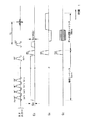
第1の実施形態を図1〜図4を参照して説明する。この実施形態にかかるMRI(磁気共鳴イメージング)装置の概略構成を図1に示す。
【0030】
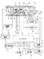
このMRI装置は、被検体Pを載せる寝台部と、静磁場を発生させる静磁場発生部と、静磁場に位置情報を付加するための傾斜磁場発生部と、高周波信号を送受信する送受信部と、システム全体のコントロール及び画像再構成を担う制御・演算部と、被検体Pの心電信号を計測する心電計測部とを備えている。
【0031】
静磁場発生部は、例えば超電導方式の磁石1と、この磁石1に電流を供給する静磁場電源2とを備え、被検体Pが遊挿される円筒状の開口部(診断用空間)の軸方向(Z軸方向)に静磁場H0 を発生させる。なお、この磁石部にはシムコイル14が設けられている。このシムコイル14には、後述するコントローラの制御下で、シムコイル電源15から静磁場均一化のための電流が供給される。寝台部は、被検体Pを載せた天板を磁石1の開口部に退避可能に挿入できる。
【0032】
傾斜磁場発生部は、磁石1に組み込まれた傾斜磁場コイルユニット3を備える。この傾斜磁場コイルユニット3は、互いに直交するX、Y、Z軸方向の傾斜磁場を発生させるための3組(種類)のx,y,zコイル3x〜3zを備える。傾斜磁場部はさらに、x,y,zコイル3x〜3zに電流を供給する傾斜磁場電源4を備える。この傾斜磁場電源4は、後述するシーケンサ5の制御のもとで、x,y,zコイル3x〜3zに傾斜磁場を発生させるためのパルス電流を供給する。
【0033】
傾斜磁場電源4からx,y,zコイル3x〜3zに供給されるパルス電流を制御することにより、物理軸としての3軸であるX,Y,Z方向の傾斜磁場を合成して、論理軸としてのスライス方向傾斜磁場GS 、位相エンコード方向傾斜磁場GE 、および読出し方向(周波数エンコード方向)傾斜磁場GR の各方向を任意に設定・変更することができる。スライス方向、位相エンコード方向、および読出し方向の各傾斜磁場は静磁場H0 に重畳される。
【0034】
送受信部は、磁石1内の撮影空間にて被検体Pの近傍に配設されるRFコイル7と、このコイル7に接続された送信器8T及び受信器8Rとを備える。この送信器8T及び受信器8Rは、後述するシーケンサ5の制御のもとで、磁気共鳴 (MR)現象を誘起させるためのラーモア周波数のRF電流パルスをRFコイル7に供給する一方、RFコイル7が受信した高周波のMR信号を受信し、各種の信号処理を施して、対応するデジタル信号を形成するようになっている。
【0035】
さらに、制御・演算部は、シーケンサ5、コントローラ6、演算ユニット10、記憶ユニット11、表示器12、入力器13、および音声発生器16を備える。この内、コントローラ6はコンピュータを有し、このコンピュータに記憶させたソフトウエア手順により、シーケンサ5にスキャンシーケンス情報を指令するとともに、シーケンサ5を含む装置全体の制御ブロックの動作タイミングの同期をとりながら、それらの制御を統括する機能を有する。
【0036】
このMRI装置は、対象となる撮像スライスのMRデータを収集する前に、この撮像スライスに流入する血流を含み且つ撮像スライスとは異なる事前励起スライス(例えば、ギャップあり又はギャップレスで撮像スライスに隣接する並行スライスや、角度の異なるスライス)を複数個のサチュレーションパルスでスライス選択的に事前励起し、この後、傾斜磁場スポイラーパルスを加えるという事前シーケンスを実行することを特徴とする。
【0037】
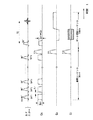
このため、コントローラ6およびシーケンサ5は共働して、図2に示すMRアンギオグラフィ用の一連のスキャンシーケンスに基づくスキャンを実施する。このスキャンシーケンスは、最初に実行する血流飽和用の事前シーケンスSQpre と、この後に実行するイメージング用のデータ収集シーケンスSQacq とで構成される。この処理は、コントローラ6が所定のメインプログラムを実行していく中でコンピュータ制御により実施される。このスキャンにより収集されたMR信号は、演算ユニット10により所定の再構成ルーチンに基づき処理され、MRA像が作成される。
【0038】
シーケンサ5は、CPUおよびメモリを備えており、コントローラ6から送られてきたスキャンシーケンス情報を記憶し、この情報にしたがって傾斜磁場電源4、送信器8T、受信機8Rの一連の動作を制御する。ここで、スキャンシーケンス情報とは、一連のスキャンシーケンスにしたがって傾斜磁場電源4、送信器8Tおよび受信器8Rを動作させるために必要な全ての情報であり、例えばx,y,zコイル3x〜3zに印加するパルス電流の強度、印加時間、印加タイミングなどに関する情報を含む。また、シーケンサ5は必要に応じて、上述したタイミング制御をECG信号のゲートパルスに同期して実施し、心電同期を行えるようになっている。
【0039】
このスキャンシーケンスの一部を成すデータ収集シーケンスとしては、例えばフーリエ変換法を適用した2次元(2D)スキャンが採用される。また、そのパルス列の形態としては、SE(スピンエコー)法、FE(フィールド・グラジェントエコー)法、FSE(高速SE)法、FASE法(高速SE法とハーフフーリエ法を組み合わせた方法)、FLAIR(FLuid Attenuated Inversion Reco-very)法、高速FLAIR法、EPI(Echo Planar Imaging) 法、ハイブリッド EPI法など、広範囲に及び各種のパルス列を採用できる。
【0040】
また、演算ユニット10は、受信器8RからのMR信号のデジタルデータを入力して内蔵メモリで形成されるフーリエ空間(k空間または周波数空間とも呼ばれる)への原データ(生データとも呼ばれる)の配置、および、原データを実空間画像に再構成するための2次元または3次元のフーリエ変換処理を行うようになっている。また、この演算ユニット10は必要に応じて、3次元画像データを最大値投影(MIP)処理に掛けて、2次元像を作成する機能をも有する。
【0041】
記憶ユニット11は、原データおよび再構成画像データのみならず、演算処理が施された画像データなどを保管することができる。表示器12は画像を表示する。また、術者は入力器13を介して所望のスキャン条件、スキャンシーケンス、画像処理法などの必要情報をコントローラ6に入力できるようになっている。
【0042】
音声発生器14は、必要に応じて、コントローラ6から指令があったときに、撮像中の息止め開始および息止め終了のメッセージを音声として発することができる。
【0043】
さらに、心電計測部は、被検体の体表に付着させてECG信号を電気信号として検出するECGセンサ17と、ECG信号中のR波のピーク値に同期した微小幅のゲートパルスを心電同期信号としてコントローラ6およびシーケンサ5に出力するECGユニット18とを備える。この心電計測部によるゲートパルスは、必要に応じて、スキャン開始タイミングの制御に心電同期信号としてシーケンサ5により利用される。これにより、心電同期タイミングを適切に設定でき、この設定した同期タイミングに拠る心電同期スキャンを行ってMR原(生)データを収集できるようになっている。
【0044】
次に、この実施形態の動作を説明する。
【0045】
このMRI装置が起動すると、コントローラ6は所定メインプログラムを実行する中で、図2に示すスキャンシーケンスを実行する。このシーケンスの実行に拠るパルス印加は、シーケンサ5の制御の元、x,y,zコイル3x〜3z及びRFコイル7を介して実施される。
【0046】
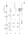
同図に示すように、このスキャンシーケンスは、スピン(磁化)を飽和させるサチュレーションパルス(飽和パルス)を含んだサチュレーションシーケンスとしての事前シーケンスSQpre と、この事前シーケンスSQpre に続いて印加するMR信号収集用のデータ収集シーケンスSQacq とから成る。
【0047】
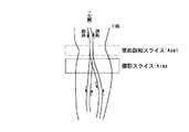
まず、事前シーケンスSQpre においては、フリップ角FA=90°のn個 (n≧2:例えばn=10)のサチュレーションパルスSAT1 〜SATn をスライス用傾斜磁場GS (=強度GS1)と共に一定時間毎に印加する。このサチュレーションパルスSAT1 〜SATn のそれぞれは、例えば、所定RF周波数のキャリア信号をシンク関数で変調して形成されるRFパルスである。診断部位を例えば図3に示す如く下肢とすると、スライス用傾斜磁場GS =GS1の例えば強度を適宜に設定することで、所望の撮影スライスAima の動脈流入側のほぼ隣接した所定厚さの平行な事前飽和スライスAsat が設定される。この結果、事前飽和スライスAsat の同一面に、サチュレーションパルスSAT1 〜SATn が一定時間毎に順次印加される。
【0048】
なお、スライス用傾斜磁場GS の例えば強度を調節することで、事前飽和スライスAsat を撮影スライスAima の動脈流出側、すなわち静脈流入側に設定することができる。また撮影スライスAima と事前飽和スライスAsat との間に必要に応じてギャップを設けてもよいし、ギャップレスの状態に設定してもよい。
【0049】
さらに事前シーケンスSQpre において、サチュレーションパルスSAT1 〜SATn のそれぞれの印加直後に、スライス方向、読出し方向、および位相エンコード方向のそれぞれに、スポイラーパルスSPs1〜SPsn、SPr1〜SPrn、およびSPe1〜SPenをそれぞれ印加する。
【0050】
この結果、最初に、事前飽和スライスAsat がサチュレーションパルスSAT1 およびスライス用傾斜磁場GS により選択励起される。これにより、このスライスAsat を通る血流(動脈および静脈)が励起され、そのスピンが飽和する。この励起によって横磁化に残っているスピンは、その後のスポイラ−パルスSPs1、SPr1、SPe1によって各傾斜磁場方向において夫々分散される。このサチュレーションパルス及びスポイラーパルスの印加の繰返しがn回(例えば10回)行われる。
【0051】
このように、事前飽和スライスAsat が複数回にわたって励起されるから、下肢などの遅い流速の血流であっても、その血流のスピンは確実に励起・飽和する。この飽和したスピンの内、動脈流がその後に撮影スライスAima に流入して撮影に関与するが、静脈流は事前飽和スライスAsat から腎臓側に流出するだけであり、撮影には関与しない。
【0052】
上記事前シーケンスSQpre に続いて、撮影スライスAima のデータ収集シーケンスSQacq の各パルスがシーケンサ5の制御の元に被検体Pに印加される。このシーケンスSQacq は例えばFE(フィールドエコー)法に基づいて設定されている。このときのスライス用傾斜磁場GS の強度はGS =GS2≠GS1である。被検体Pからのエコーデータ(MR信号)は、受信器8Rでデジタルデータに処理され、演算ユニット10に順次格納される。演算ユニット10はコントローラ6からの再構成指令に応答して、2次元k(フーリエ)空間上に配置したエコーデータの組を2次元フーリエ変換して断層像、すなわちMRA像を生成する。
【0053】
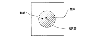
事前シーケンスSQpre の複数個のサチュレーションパルスの印加によって、撮影スライスAima には十分に飽和した動脈流スピンが流入する一方で、事前飽和スライスAsat とは反対側の、下肢で言えば心臓に遠い側から飽和されていないフレッシュな静脈も流入している。このため、データ収集シーケンスSQacq でデータ収集するとき、動脈流からのエコー信号の信号値は非常に低く、静脈流からのそれは高い。
【0054】
したがって、演算ユニット10で再構成して得られるMRA像には図4に示す如く、信号値低下によって画素値抜けした動脈と、信号値が確保できて血流跡の画素値を得る静脈とが写り込むので、動静脈を視覚的に良好に分離できた画像となる。
【0055】
この実施形態において、小さなフリップ角(ここでは90°)の複数個のサチュレーションパルスは同一の事前飽和スライスAsat に断続的に印加される。これは、とりも直さず、撮影スライスAima にとっては一定の周波数オフセットをもって、この小さなフリップ角で断続的に励起されることにもなる。撮影スライスAima の実質部は動いていないから、サチュレーションパルスのフリップ角FA=90°でn=10個の場合、実質部は、トータルで90°×10(=n)=900°のフリップ角によるMT(magnetization transfer)効果を受ける。この結果、実質部からのMR信号値が低下する。
【0056】
一方、撮影スライスAima に流入する静脈流の場合、血流が移動しており、かつ、小さなフリップ角(ここでは90°)に分けて印加されることと等価であるから、そのMT効果は実質部よりも小さく、最小限に抑制される。また撮影スライスAima に流入する動脈流にとっては、血流が流れているので、MT効果が少なく、フリップ角FA=90°としてだけの効果が支配的となる。この結果、再構成されるMRA像の血流/実質部のコントラストが著しく向上する。
【0057】
さらに、この実施形態のMRA像はMR造影剤を使用するものでないから、通常のMRイメージングの非侵襲性の特性を生かしたものとなる。このため、造影剤を使用したMRA像の撮影に比べて、患者の精神的、体力的負担が著しく少なくて済む。
【0058】
第2の実施形態
本発明の第2の実施形態を図5に基づき説明する。この実施形態は、事前シーケンスにおいて印加する傾斜磁場スポイラーパルスの印加数の節約に関する。
【0059】
なお、本実施形態以降の実施形態において、前述した第1の実施形態におけるMRI装置と同一または同等の構成要素には同一の符号を用いて、その説明を省略または簡略化する。
【0060】
本実施形態のMRI装置のシーケンサ5は、図5に示す撮影のためのスキャンシーケンスを実行するようになっている。
【0061】
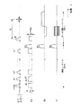
図5のスキャンシーケンスは、第1の実施形態のときと同様に、事前シーケンスSQpreとデータ収集シーケンスSQacqとを含む。このスキャンシーケンスは第1の実施形態のものと比較して、データ収集シーケンスSQaquが同一に設定されている一方で、事前シーケンスSQpreのスポイラーパルスの設定数が異なる。具体的には、フリップ角FA=90°の複数n個のサチュレーションパルスSAT1〜SATnが所定時間間隔Δt毎にスライス用傾斜磁場GS=強度G S1 と共に順次印加される。スポイラーパルスは最後のサチュレーションパルスSATnが印加された後に、スライス方向、読出し方向、位相エンコード方向それぞれにおいてエンドスポイラとして1個だけ印加される。このスポイラーパルスの印加後に、データ収集シーケンスSQacqが前述と同様に続く。
【0062】
このように最後のサチュレーションパルスSATnの印加後に、各傾斜磁場方向に1個のスポイラーパルスSPs,SPr,SPeを印加することによっても、横磁化に残ったまま撮影スライスAimaに入ろうとする、及び、撮像スライスAimaに残っている不要なスピン(実質部と血液の両スピン)を確実に分散させることができ、撮影スライスA imaのアーチファクトを抑制できる。これにより、「血流は流れているので、必ずしも各飽和毎にスポイル(分散)させる必要はない」ことに着目した、スポイラーパルスの効果的な且つ時間節約タイプの印加法になっている。
【0063】
このため、第2の実施形態においても前述した第1の実施形態のものと同一または同等の作用効果を得るとともに、事前シーケンスの印加時間の短縮を図ることができる。つまり、実質部と血流との良好なコントラストを保持できるとともに、動静脈を確実に分離したMRA像を、非侵襲で、より高速に提供することができる。
【0064】
第3の実施形態
さらに、本発明の第3の実施形態を図6及び図7に基づき説明する。この実施形態は、サチュレーションパルスのフリップ角を可変にした構成に関する。
【0065】
本実施形態のMRI装置のシーケンサ5は、図6に示す撮影のためのスキャンシーケンスを実行するようになっている。
【0066】
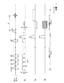
この図6のスキャンシーケンスは、第1の実施形態のときと同様に、事前シーケンスSQpreとデータ収集シーケンスSQacqとを含む。このパルスシーケンスは第1の実施形態のものと比較して、データ収集シーケンスSQacqが同一に設定されている一方で、事前シーケンスSQpreのスポイラーパルスの設定数が異なる。また、フリップ角を各パルス毎に変えた複数n個のサチュレーションパルスSAT1〜SATnが所定時間間隔Δt毎にスライス用傾斜磁場GS=強度G S1 と共に順次印加される。スポイラーパルスSP s ,SP r ,SP e は最後のサチュレーションパルスSATnが印加された後に、スライス方向、読出し方向、位相エンコード方向それぞれで1個だけ印加される。このスポイラーパルスSP s ,SP r ,SP e の印加後に、データ収集シーケンスSQacqが前述と同様に続く。
【0067】
複数n個のサチュレーションパルスSAT1 〜SATn のフリップ角FAは、一例として、1番目のFA=90°、2番目のFA=85°、3番目のFA=80°、…、最終番目のFA=60°の如く漸減するフリップ角系列が選択されている。この漸減するフリップ角系列を選択する理由は以下のようである。
【0068】
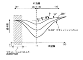
図7のグラフは、スピンの共鳴周波数(スライス位置に相当)を横軸に、MR信号値を縦軸にとって、1つのサチュレーションパルス当たりのフリップ角FAをパラメータとしたときの信号値の変化の様子を示す。横軸に示す周波数f0 は、撮影スライスの中心位置での水の共鳴周波数(中心周波数)である。このグラフから分かるように、周波数が中心周波数f0 に近付くほど、またフリップ角FAが大きくなるほど、信号値が低下してMT効果が大きい。
【0069】
このため、サチュレーションパルスのフリップ角FAを経時的後ろのものほど低下させるということは、撮影スライスAima に注入する静脈流(図3参照)にとって、その血流のある注目位置が中心周波数f0 (撮像スライス位置)に近付くほどMT効果を緩和する(下げる)ことになる。この状態を図7に模式的に表すと、フリップ角FA=90°の曲線から分岐する曲線Dに相当する(同図は、サチュレーションパルスの周波数範囲が横軸(−)側に位置している場合を示す)。そこで、事前飽和スライスAsat の反対側から流入する血流(ここでは静脈流)のMR信号値の低下は最小限に抑えられ、比較的高い信号値が得られる。
【0070】
一方、撮影スライスAima の実質部は前述と同様に、複数n個のサチュレーションパルスの事前飽和スライスAsat への印加に伴って、そのスライス位置の相違分だけ一定の周波数オフセット(off resonance )の状態で励起されるから、大きなMT効果を発生させ、MR信号値が低下する。
【0071】
したがって、本第3の実施形態のMRI装置にあっては、前述した第2の実施形態のものと同一または同等の作用効果を得るとともに、撮影スライスの実質部/血流のコントラストを一層高めることができ、高画質の視認性に優れたMRA像を提供することができる。
【0072】
なお、本第3の実施形態において、複数のサチュレーションパルスのフリップ角FAは時系列後方のパルスになるほど、例えば90°、90°、80°、80°、…、60°、60°のように変化させる手法であってもよい。
【0073】
また、第3の実施形態の1つの変形例として、撮影スライスから流出する血流の飽和効果を促進する必要がある場合、複数のサチュレーションパルスのフリップ角FAは時系列後方のパルスになるほど、例えば60°、65°、70°、75°、…、85°、90°のように、大きな値に向かうように変化させることもできる。
【0074】
第4の実施形態
さらに、本発明の第4の実施形態を図8に基づき説明する。この実施形態のMRI装置は、前述した第2の実施形態のスキャンシーケンスをさらに改善したもので、とくに、事前シーケンスSQpre の時間短縮に関する。
【0075】
図8に、この実施形態のMTI装置が採用するスキャンシーケンスを示す。同図から分かるように、このスキャンシーケンスで用いているサチュレーションシーケンスとしての事前シーケンスSQpre では、事前飽和スライスAsat に選択的にサチュレーションパルスSAT1 〜SATn を印加するが、各サチュレーションパルスと共に印加するスライス用傾斜磁場パルスGS を連続的に印加するもので、各パルス間に前述した各実施形態で設定していたΔtの時間間隔を排除している。
【0076】
これにより、複数n個のサチュレーションパルスSAT1 〜SATn を印加するための必要なトータルの時間が「Δt×(n−1)」の分だけ短縮され、結局、MRアンギオグラフィの撮像時間が短縮されるという効果がある。
【0077】
第5の実施形態
本発明の第5の実施形態を図9に基づき説明する。この実施形態のMRI装置も、上述した第4の実施形態のスキャンシーケンスをさらに改善したもので、とくに、事前シーケンスSQpre の時間短縮およびスライス用傾斜磁場GS のスイッチング時の負荷軽減に関する。
【0078】
図9に、この実施形態のMTI装置が採用するスキャンシーケンスを示す。同図から分かるように、このスキャンシーケンスで用いている事前シーケンスSQpre では、複数n個のサチュレーションパルスSAT1 〜SATn と共に印加するスライス用傾斜磁場GS をそれらのサチュレーションSAT1 〜SATn 全部の印加時間に合わせて連続的に印加するように設定したものである。
【0079】
これにより、第4の実施形態のときと同様に、パルス間の間隔Δtに起因した約「Δt×(n−1)」の時間短縮に加えて、傾斜磁場パルスGS のスリューレート分の時間Δts (例えば0.6〜1msec)も不要になり、約「Δts ×(2n−2)」分の更なる時間短縮がなされる。
【0080】
この結果、MRアンギオグラフィの撮像時間も短縮されるとともに、傾斜磁場GS を極めて短時間でオン・オフするときのスイッチング時の負荷が緩和されることになり、傾斜磁場電源4およびx,y,zコイル3x,3y,3zのスイッチング特性の要求条件も緩和でき、設計面での容易化が可能になる。
【0081】
第6の実施形態
本発明の第6の実施形態を図10に基づき説明する。この実施形態のMRI装置は、本発明独特の複数個のサチュレーションパルスを含むサチュレーションシーケンスを高速FLAIR法に組み込んだものである。
【0082】
つまり、図10に示すように、この実施形態のMRI装置が採用するスキャンシーケンスは、シングルスライス撮像用であり、インバージョン(反転)パルスInv及びサチュレーションシーケンスSQsat を含む事前シーケンスSQpre と、高速SE法(FSE法またはRARE法とも呼ばれる)から成るデータ収集シーケンスSQacq とを含む。この内、インバージョンパルスInvと高速SE法のデータ収集シーケンスSQacq が高速FLAIR(Fast FLuid Attenuaed with Inversion Recovery)を成す。この高速SE法は、ここでは、脂肪抑制を行うためのPASTA(Polarity altered spectral and spatial selective acquisition )法に基づいて実施する。このPASTA法は例えば,「SMR 1995 #657 "A Polarity Altered Spectral and Spatial Selective Acquisition Technique" 」で知られている。
【0083】
なお、このデータ収集シーケンスSQacq を通常SE法で構成することもでき、この場合は、FLAIR法に、本発明独特のサチュレーションシーケンスのパルスを組み入れたことになる。
【0084】
図10に示すサチュレーションシーケンスSQsat は、事前シーケンスSQpre の一部として実施されるパルス列で、サチュレーションパルス列Tsatおよび傾斜磁場スポイラーパルスSPs ,SPr ,SPe から成る。このサチュレーションシーケンスSQsat は、前述した第4の実施形態のものと同様に構成されている。
【0085】
このスキャンシーケンスによれば、最初に、撮像スライスAima (図3参照)対するインバージョンパルスInvとスライス用傾斜磁場GS とが並行して印加される。インバージョンパルスInvは、例えば180°RFパルスで構成される。インバージョンパルスInvは送信機8TからRFコイル7を介して、またスライス用傾斜磁場GS は傾斜磁場電源4から傾斜磁場コイル3z、3zを介してそれぞれ印加される。この傾斜磁場GS は撮像スライスを選択できるようにその強度が設定されている。
【0086】
このインバージョンパルスInvの印加が終わると、高速FLAIR法としては、所要の反転時間(遅延時間)TI の間待機することになるが、本実施形態では、この反転時間TI を利用して、この時間の間に、サチュレーションパルス列Tsatおよび傾斜磁場スポイラーパルスSPs ,SPr ,SPe から成るサチュレーションシーケンスSQsat が図示の如く実行される。サチュレーションパルス列Tsatは、前述と同様に、複数個のサチュレーションパルスSAT1 ,SAT2 ,…,SATn およびこれと並行して印加される複数個のスライス用傾斜磁場パルスGS で形成される。
【0087】
このサチュレーションシーケンスSQsat の実行により、前述と同様に、事前飽和スライスAsat を通る血流のスピンが飽和され、また、オフ・レゾナンスとなる撮像スライスAima にはMT効果が生じる。
【0088】
この反転時間TI が経過すると、インバージョンパルスInvにより反転励起させていた撮像スライスAima に対してデータ収集シーケンスSQacq が実行される。すなわち、PASTA法に基づく高速SE法のパルス列が印加される。
【0089】
最初に、スライス用傾斜磁場GS と水スピンのみを周波数選択的に励起する狭い周波数帯域の90°RFパルスが印加される。これにより、撮像スライスAima が選択されるとともに、そのスライス内の水のみの磁化スピンが励起され、y′軸(回転座標)までフリップする。次いで、このスライス用傾斜磁場GS が極性反転して一種のリフェーズパルスとして印加される。また、読出し用傾斜磁場GR が傾斜磁場コイル3x、3xを介して印加される。これは撮像スライス内の読出し方向に並んだスピンの位相が各エコーの中心時刻において揃うようにするためである。
【0090】
次いで、逆極性で高強度のスライス用傾斜磁場GS と広い周波数帯域の最初の180゜RFパルスが印加される。これにより、プロトンスピンが180度、y′軸の回りに回転する。これにより、水のプロトンスピンに対してのみエコー信号のリフォーカスが行われる。さらに、最初の位相エンコード用傾斜磁場GE =Aが傾斜磁場電源4から傾斜磁場コイル3y、3yを介して被検体Pに印加された後、傾斜磁場コイル3x、3xを介して印加される読出し用傾斜磁場GR とともに、最初のスピンエコー信号R1がRFコイル7を介して収集される。
【0091】
この後、反転させた位相エンコード用傾斜磁場GE =−Aを印加させる。これは疑似エコー(stimulated echo)による画質劣化を避けるため、180゜RFパルスの印加時のエンコード位置をk空間上の位相エンコード方向の中心位置(ke=0)に引き戻すためである。
【0092】
次いで、第1番目のときと同様に、スライス用傾斜磁場GS とともに2番目の180゜RFパルスを印加した後、2番目の位相エンコード用傾斜磁場GE =Bを印加する。そして、2番目のスピンエコー信号R2が、読出し用傾斜磁場GR の印加とともに、RFコイル7を介して収集される。
【0093】
同様にして、3番目及び4番目のスピンエコー信号R3およびR4が収集される。
【0094】
以上のスキャンシーケンスの実行は、位相エンコード量毎に、所定の繰返し時間TRで繰り返される。
【0095】
この収集に係るシングルスライススキャンのエコー信号は、PASTA法に拠って、その殆ど水のプロトンスピンから収集されたものであり、受信器8Rに順次送られる。受信器8Rでは、エコー信号は、増幅、中間周波変換、位相検波、低周波増幅などの処理を受けた後、A/D変換されてエコーデータに生成される。このエコーデータは演算ユニット10で、フーリエ変換可能な、k空間に対応したメモリ領域にデータが配置される。そして2次元フーリエ変換により実空間のMRA像に再構成される。この画像は記憶ユニット13に記憶されるとともに、表示器14に表示される。
【0096】
このように、高速FLAIR法にサチュレーションシーケンスSQsatを適用した場合でも、前述した実施形態のものと同等の作用効果を得ることができるとともに、高速FLAIR法に基づく撮像であることから、とくに、スライス枚数の増加と動静脈の分離ができるという利点が得られる。また、サチュレーションシーケンスTsatを反転時間TIの間で実行することから、高速FLAIR法に基づくスキャン時間を格別長くするものではない。一方、適用できるデータ収集シーケンスの幅も広がり、本発明の特徴であるサチュレーションシーケンスの汎用性が高まる。さらに、PASTA法に基づくデータ収集であるから、撮像スライスAimaの脂肪抑制効果(脂肪からのエコー信号収集を抑制する効果)も合わせて享受できる。
【0097】
第7の実施形態
さらに、本発明の第7の実施形態を図11〜13に基づき説明する。この実施形態のMRI装置は、本発明独特の複数個のサチュレーションパルスを含むサチュレーションシーケンスを第6の実施形態と同様に高速FLAIR法に組み込み、且つ、それを入れ子方式のマルチスライス法で実施したものである。
【0098】
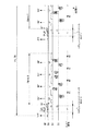
図11に、本発明独特の高速FLAIR法を入れ子方式(nesting )のマルチスライス法で実施したスキャンシーケンス全体の概要を示す。図12は、このスキャンシーケンスをスライス位置との対応関係で示す。さらに、図13には、そのスキャンシーケンスの最初の一部の詳細なパルス列を示す。
【0099】
図12(a)には、マルチスキャンに拠る7枚の撮像スライスAima-1 〜Aima-7 の一例を、また、各撮像スライスに対応して設定される7枚の事前飽和スライスApre-1 〜Apre-7 の一例を模式的に示す。
【0100】
図11および図12(b)に示すスキャンシーケンスは、シーケンシャルモードの入れ子方式の例を示す。高速FLAIR法を成すインバージョンパルスInv1〜Inv7の7個と、これに対応するデータ収集シーケンス(イメージングシーケンス)Imaging1〜Imaging7の7個とを使用するとともに、各撮像スライスにインバージョンパルスInvを印加した後の反転時間TI の間に、2枚の撮像スライスAima に相当する分のインバージョンパルスInv、サチュレーションシーケンスSQsat 、およびデータ収集シーケンスSQacq をシーケンシャルに実行し、全体のスキャン時間の短縮を図っている。各撮像スライスに対するインバージョンパルスInv及びサチュレーションシーケンスSQsat が本発明の事前シーケンスSQpre に相当する。なお、データ収集シーケンスImaging1〜Imaging7はPASTA法に基づいている。
【0101】
各撮像スライスに対するインバージョンパルスInv、サチュレーションシーケンスSQsat 、およびデータ収集シーケンスSQacq は、前述した図10のものと同様に形成される。
【0102】
このシーケンシャルモードに入れ子方式によれば、最初に、1番目の撮像スライスAima-1 にインバージョンパルスInv1が印加され、その所定時間後に、既にインバージョンパルスInv6を印加していた撮像スライスAima-6 に対する事前飽和スライスApre-6 にサチュレーションシーケンスSQsat-6 を実行し、さらに、その撮像スライスAima-6 にデータ収集シーケンスSQacq-6 を実行する。
【0103】
この所定時間後に、2番目の撮像スライスAima-2 にインバージョンパルスInv2を印加する。この後、所定時間を置いて、既にインバージョンパルスInv7を印加していた撮像スライスAima-7 に対する事前飽和スライスApre-7 にサチュレーションシーケンスSQsat-7 を実行し、さらに、その撮像スライスAima-7 にデータ収集シーケンスSQacq-7 を実行する。
【0104】
さらに所定時間を置いて、3番目の撮像スライスAima-3 にインバージョンパルスInv3を印加する。さらに再び、所定時間の後、先程、インバージョンパルスInv1を印加した撮像スライスAima-1 に対する事前飽和スライスApre-1 にサチュレーションシーケンスSQsat-1 を実行し、その所定時間後に、その撮像スライスAima-1 にデータ収集シーケンスSQacq-1 を実行する。
【0105】
そして、再び所定時間後、4番目の撮像スライスAima-4 にインバージョンパルスInv4を印加する。以下、同様にしてパルス印加およびMR信号収集を行い、最後には、5番目の撮像スライスAima-5 にデータ収集シーケンスSQacq-5 を実行して、繰返し時間TRを終える。
【0106】
このようにすることで、インバージョンパルスとデータ収集シーケンス(本シーケンス)との間の反転時間を有効に利用でき、スライス枚数を増加させることができ、しかも、全体のスキャン時間の長期化を回避したイメージングを提供できる。
【0107】
第8の実施形態
さらに、本発明の第8の実施形態を図14に基づき説明する。この実施形態のMRI装置は、第7の実施形態で説明したスキャン法の入れ子方式を別のモード、すなわち「インターリーブモード」に変更したものである。
【0108】
この実施形態のMRI装置において、このモード以外の構成および機能は第7の実施形態のものと同一または同様である。
【0109】
このインターリーブモードの入れ子方式によれば、図14に示す如く、最初に、1番目の撮像スライスAima-1 にインバージョンパルスInv1が印加され、その所定時間後に、既にインバージョンパルスInv4を印加していた撮像スライスAima-4 に対する事前飽和スライスApre-4 にサチュレーションシーケンスSQsat-4 を実行し、さらに、その撮像スライスAima-4 にデータ収集シーケンスSQacq-4 を実行する。
【0110】
この所定時間後に、3番目の撮像スライスAima-3 にインバージョンパルスInv3を印加する。この後、所定時間を置いて、既にインバージョンパルスInv6を印加していた撮像スライスAima-6 に対する事前飽和スライスApre-6 にサチュレーションシーケンスSQsat-6 を実行し、さらに、その撮像スライスAima-6 にデータ収集シーケンスSQacq-6 を実行する。
【0111】
さらに所定時間を置いて、5番目の撮像スライスAima-5 にインバージョンパルスInv5を印加する。さらに再び、所定時間の後、先程、インバージョンパルスInv1を印加した撮像スライスAima-1 に対する事前飽和スライスApre-1 にサチュレーションシーケンスSQsat-1 を実行し、その所定時間後に、その撮像スライスAima-1 にデータ収集シーケンスSQacq-1 を実行する。
【0112】
そして、再び所定時間後、7番目の撮像スライスAima-7 にインバージョンパルスInv7を印加する。以下、同様にしてパルス印加およびMR信号収集を行い、最後には、2番目の撮像スライスAima-2 にデータ収集シーケンスSQacq-2 を実行して、繰返し時間TRを終える。
【0113】
このように同じ高速FLAIR法を利用したマルチスライスシーケンスでありながら、撮像スライスを4、6、1、5、7と1枚置きに選択するので、第7の実施形態の効果に加え、スライス間のスピンの干渉をより確実に排除して画質を向上させることができるなどの、更なる利点がある。
【0114】
なお、上記各実施形態では、複数個のサチュレーションパルスを撮影スライスの動脈流入側に設定したスライス(事前飽和スライス)に印加する例を中心に説明したが、本発明は必ずしもこれに限定されるものではない。複数個のサチュレーションパルスを撮影スライスの動脈流出側(静脈流入側)に設定したスライス(図3の場合、撮影スライスAima の図中下側)に印加するようにしてもよい。その場合、動静脈の信号値の大小関係が反対になるが、動静脈を良好に分離した、実質部/血流のコントラストの高いMRA像を非侵襲で得ることができる。
【0115】
また、上記各実施形態において、スポイラーパルスは任意の1方向または2方向のみに印加するようにしてもよい。
【0116】
【発明の効果】
以上説明したように、本発明に係るMRアンギオグラフィのデータ収集方法およびMRI装置によれば、
血流の原子核スピンを飽和させる複数個の飽和パルスを含む事前シーケンスを撮影スライスとは異なる被検体の同一スライスに時系列的に順次印加するようにし、例えば、その事前シーケンスは、複数個の飽和パルスのそれぞれの印加後に印加する血流スピン分散用のスポイラーパルスを含んだり、複数個の飽和パルスの内の時系列的に最後尾の飽和パルスの印加後に印加する血流スピン分散用の1個のスポイラーパルスを含むようにしたため、1)血流の流速が早すぎたり遅すぎる場合でも、動脈または静脈の信号を確実に抑制でき、動静脈を視覚的に確実に分離したMRA像であって、2)複数のサチュレーションパルスを同一面に印加することで、撮影スライスの静止している実質部に大きなMT効果を起こさせ、かつ、流れている血流のMT効果は小さく抑えて、飽和させる血流(動脈または静脈)に1個分のサチュレーションパルスだけの機能を与えることができ、これにより血流/実質部のコントラストの高い、視認性に優れたMRA像を、3)造影剤を使用しない非侵襲の状態で提供できる。
【図面の簡単な説明】
【図1】本発明の実施形態に係るMRI装置の一例を示すブロック図。
【図2】第1の実施形態に係るスキャンシーケンスの一例を示す図。
【図3】第1の実施形態に係る撮影スライス、事前飽和スライス、および血流の走行状態の一例を説明する図。
【図4】第1の実施形態で得られるMRA像の一例を模式的に示す図。
【図5】第2の実施形態に係るスキャンシーケンスの一例を示す図。
【図6】第3の実施形態に係るスキャンスシーケンスの一例を示す図。
【図7】フリップ角の可変に伴うMT効果の変化を説明する図。
【図8】第4の実施形態に係るスキャンシーケンスの一例を示す図。
【図9】第5の実施形態に係るスキャンスシーケンスの一例を示す図。
【図10】第6の実施形態に係る高速FLAIR法を利用したシングルスライスのスキャンスシーケンスの一例を示す図。
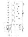
【図11】第7の実施形態に係る高速FLAIR法を利用したマルチスライスのスキャンスシーケンスの全体を示す図。
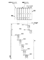
【図12】第7の実施形態に係るスキャンスシーケンスとスライス位置との対応関係を明確にした図。
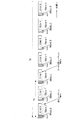
【図13】図11のスキャンシーケンスの最初の一部を詳細に示すパルス列の図。
【図14】第8の実施形態に係る高速FLAIR法を利用したマルチスライスのスキャンスシーケンスの全体を示す図。
【符号の説明】
1 磁石
2 静磁場電源
3 傾斜磁場コイルユニット
4 傾斜磁場電源
5 シーケンサ
6 コントローラ
7 RFコイル
8T 送信器
8R 受信器
10 演算ユニット
11 記憶ユニット
12 表示器
13 入力器[0001]
BACKGROUND OF THE INVENTION
The present invention relates to MR angiography (MR angiography) using the magnetic resonance phenomenon of nuclear spins in a subject, and more particularly to saturation pulses (arteriovenous separation and body motion artifact suppression applied together with slice selection pulses). The present invention relates to improvement of MR angiography using spin saturation pulses.
[0002]
[Prior art]
In MR (magnetic resonance) imaging, the nuclear spin of a subject placed in a static magnetic field is magnetically excited with a high-frequency signal of Larmor frequency, and an image is reconstructed based on the MR signal generated by this excitation. Or a technique for obtaining a spectrum.
[0003]
In the field of MRI, MR angiography for imaging a blood flow in a subject and measuring the flow velocity has already been performed in a medical field. One of the MR angiography techniques is a technique of applying a saturation pulse for saturation called a saturation pulse together with a slice selection pulse.
[0004]
In the conventional case, this saturation pulse (saturation pulse) is applied to the cross section upstream or downstream of the blood flow flowing through the imaging section before applying the pulse of the MR signal acquisition sequence. For example, in the lower limbs, the flow directions of the artery and vein are opposite to each other, so one (times) saturation pulse is applied to the cross section upstream or downstream of the artery or vein in the imaging section, and thereafter The echo signals of the imaging section are collected by, for example, the FE method. As a result, the spin (magnetization) of the artery or vein flowing into the imaging section is already excited and saturated, so that the MR signal value of the blood flow is lowered. Since the saturation pulse is not applied to the vein or artery flowing from the opposite side to the imaging section, a high value of the MR signal is collected. For this reason, the MRA image of the imaging section obtained by reconstructing the acquired data should be an arteriovenous separation image in which the artery and vein are separated.
[0005]
However, in reality, if the flow rate of the blood flow to be imaged is too fast or too slow (especially slow in the lower limbs) or pulsating blood, flow void phenomenon or saturation spin inflow may occur. Saturation pulses are less effective due to being extremely slow. If the spin is not sufficiently saturated in this way, naturally, a clear arteriovenous separation image cannot be obtained.
[0006]
Especially in the lower limbs and hands,Peripheral blood vesselsThe blood flow velocity generally becomes significantly slower due to pulsation. That is, since the time-of-flight effect is small, in the case of the sequence using the saturation pulse of the conventional method, the imaging of the blood flow of the lower limb itself is almost difficult. In addition, for example, in the case of a knee disease, the current situation is far from meeting the demands of medical sites that want to separate and image arteries and veins.
[0007]
Under such circumstances, there is a study that attempts to separate such an arteriovenous vein by an MR angiography technique different from the sequence using the saturation pulse. This study is an attempt to inject an MR contrast agent into a subject and separate the arteries and veins based on the difference in temporal changes between the arterial contrast and the vein contrast.
[0008]
[Problems to be solved by the invention]
However, in the MR angiography method using the MR contrast agent, since the contrast agent is injected, the invasiveness is large, so that the physical and mental burden of the patient is very large.
[0009]
Furthermore, when MR contrast agent is used, the contrast effect in the lower limbs is thin, so the difference in peak time between the arteries and veins cannot be expected so much, and arteriovenous separation is almost difficult.
[0010]
As described above, the conventional MR angiography is not suitable for any part where the blood flow velocity is extremely small, such as the lower limbs or the hands, and it is desired to obtain a good separation image of the arteries and veins in a non-invasive state. In practice, it was almost difficult to meet the needs of the clinic.
[0011]
The present invention has been made in order to overcome the current state of the prior art. Specifically, the present invention provides an MRA image with improved blood flow / parenchymal contrast even when the blood flow velocity is remarkably large or small while maintaining the original non-invasive nature of MR imaging. That is the purpose.
[0012]
Another object of the present invention is to provide an MRA image in which the contrast of the blood flow / substantial portion is improved and at the same time the arteriovenous is visually separated.
[0013]
It is another object to allow such blood flow / parenchymal contrast improvement and reliable arteriovenous separation to be performed with various types of imaging sequences.
[0014]
[Means for Solving the Problems]
In order to achieve the above object, according to one aspect of the MRI apparatus of the present invention, an MRI apparatus for obtaining a blood flow image of an imaging slice of a subject is set at a position different from the imaging slice in the subject. Performing a pre-sequence comprising a plurality of saturation pulses applied in time series to the saturation slice, the pre-sequence comprising:Using a required inversion time, a saturation pulse train that is a plurality of saturation pulses is applied, and a saturation sequence is executed in which a spoiler pulse is applied only after the last saturation pulse of the saturation pulse train is applied.First execution means, second execution means for executing a data acquisition sequence for acquiring MR signals from the imaging slice after execution of the pre-sequence, and an image for generating the blood flow image based on the MR signals And generating means.
[0015]
In this case, preferably, the pre-sequence includes a gradient magnetic field pulse for slicing applied in parallel with the plurality of saturation pulses and for determining a slice position of the saturation slice.
[0016]
As an example, the slice gradient magnetic field pulse includes a plurality of pulses applied in parallel with each of the plurality of saturation pulses. The plurality of saturation pulses may be a pulse train arranged in time series by setting an empty time interval between adjacent saturation pulses to zero.
[0017]
As another example, the slice gradient magnetic field pulse is composed of one pulse applied in parallel with the whole of the plurality of saturation pulses.
[0018]
As yet another example, the pre-sequence may include a spoiler pulse in a gradient magnetic field direction that is applied after each of the plurality of saturation pulses.
[0019]
further,The spoiler pulse may include at least a gradient magnetic field spoiler pulse applied in the slice direction. Alternatively, the spoiler pulse may include a gradient magnetic field spoiler pulse applied in each of the three directions of the slice direction, the phase encoding direction orthogonal to the slice direction, and the reading direction.
[0020]
In the above-described preferred embodiment, as an example, the flip angles given to the spins by the plurality of saturation pulses are all the same and have a value of 100 ° or less.
[0021]
In this preferred embodiment, the flip angle that each of the plurality of saturation pulses gives to the spin may be set to a different value between at least one saturation pulse and the remaining saturation pulses. In this case, for example, each of the plurality of saturation pulses may be set so that the flip angles are different from each other. Furthermore, the flip angle of each of the plurality of saturation pulses may be a value that decreases as the saturation pulse reaches the back of the time series in time.
[0022]
Furthermore, in the above-described preferred embodiment, the slice gradient magnetic field can be set so that the saturated slice and the imaging slice are substantially parallel.
[0023]
Furthermore, in the above-mentioned preferred embodiment, the data acquisition sequence is performed on a high-speed SE sequence that forms the remaining portion of the high-speed FLAIR method that is executed at a predetermined inversion time after application of an inversion pulse that forms a part of the high-speed FLAIR method. It is also desirable to be based on a pulse train. In this case, for example, the first execution means is means for executing the preliminary sequence during the inversion time between the inversion pulse and the pulse train based on the high-speed SE sequence. The first execution means is means for repeating the pre-sequence a plurality of times based on a multi-slice method, and the second execution means performs the data acquisition sequence based on the multi-slice method. It is means for repeating the same number of times as many times as the sequence. Further, the first execution means and the second execution means are means for repeating the pre-sequence and the data collection sequence in a time series nesting manner with respect to the plurality of imaging slices based on the multi-slice method. Good.
[0024]
According to another aspect of the MRI apparatus of the present invention, in an MRI apparatus for obtaining a blood flow image of an imaging slice of a subject, a magnet that generates a static magnetic field in a space where the subject exists, and a static magnetic field A gradient coil for superimposing gradient magnetic fields for slicing, phase encoding, and reading, a gradient magnetic field generating unit for supplying a pulse current for generating the gradient magnetic field to the gradient magnetic field coil, and spin excitation for the subject An RF coil that transmits an MR signal generated by the subject, a transmission / reception unit that transmits the high-frequency signal and receives the MR signal via the RF coil, and a reception by the transmission / reception unit A reconstruction unit for reconstructing the blood flow image based on the MR signal, a gradient magnetic field generation unit, and the transmission / reception unit. The controlled and a sequencer to perform the desired scan sequence, the scan sequence, the plurality of saturation pulses saturated slices set at a position different from the imaging slice in the subjectIncluding a pre-sequence and a data acquisition sequence for MR signal acquisition applied subsequent to the pre-sequence. The pre-sequence includes a saturation pulse train, which is a plurality of saturation pulses, using a required inversion time. Only after applying the last saturation pulse of the saturation pulse trainApplying a spoiler pulse and applying a slice gradient magnetic field pulse for selecting the saturation slice in parallel with the plurality of saturation pulses, and after applying the plurality of saturation pulses and the slice gradient magnetic field pulse, It is a sequence based on an algorithm for applying a pulse train of a data acquisition sequence for acquiring MR signals from an imaging slice.
[0026]
With these configurations, even when the blood flow velocity is too fast or too slow, an arterial or venous signal can be reliably suppressed, and an MRA image can be provided in which the arterial vein is reliably separated. In addition, by applying a plurality of saturation pulses to the same surface, a large MT effect is caused in the stationary substantial part of the imaging slice, and the MT effect of the flowing blood flow is suppressed to be small, and the blood flow of saturation target ( Only a saturation for one saturation pulse can be given to an artery or a vein, thereby providing a highly visible MRA image with high blood flow / substantial contrast. Furthermore, MRA images can be provided in a non-invasive state without using a contrast agent, and the mental and physical burden on the patient can be reduced.
[0027]
Further, the flip angles of the plurality of saturation pulses can be set to different values. In this case, for example, the flip angle of each of the plurality of saturation pulses can be set to a value that decreases as the saturation pulse becomes backward in time in the time series direction. As a result, a large MT effect is caused in the substantial part of the imaging section, the MT effect of the blood flow flowing into the imaging section is suppressed, and only the saturation pulse is dominantly applied to the artery or vein. As a result, an excellent contrast of blood flow / substantial portion of the imaging cross section can be secured.
[0028]
DETAILED DESCRIPTION OF THE INVENTION
Embodiments of the present invention will be described below with reference to the accompanying drawings.
[0029]
First embodiment
A first embodiment will be described with reference to FIGS. A schematic configuration of an MRI (magnetic resonance imaging) apparatus according to this embodiment is shown in FIG.
[0030]
The MRI apparatus includes a bed unit on which the subject P is placed, a static magnetic field generation unit that generates a static magnetic field, a gradient magnetic field generation unit for adding position information to the static magnetic field, a transmission / reception unit that transmits and receives high-frequency signals, A control / arithmetic unit responsible for overall system control and image reconstruction, and an electrocardiogram measurement unit for measuring an electrocardiogram signal of the subject P are provided.
[0031]
The static magnetic field generation unit includes, for example, a
[0032]
The gradient magnetic field generator includes a gradient magnetic
[0033]
By controlling the pulse current supplied from the gradient magnetic
[0034]
The transmission / reception unit includes an
[0035]
Further, the control / arithmetic unit includes a
[0036]
The MRI apparatus includes a pre-excitation slice (eg, with or without gaps) adjacent to the imaging slice that contains blood flow flowing into the imaging slice and collects MR data of the imaging slice of interest. Parallel slices and slices with different angles) are pre-excited in a slice-selective manner with a plurality of saturation pulses, and then a pre-sequence is performed in which a gradient magnetic field spoiler pulse is applied.
[0037]
For this reason, the
[0038]
The
[0039]
As a data acquisition sequence forming a part of the scan sequence, for example, a two-dimensional (2D) scan using a Fourier transform method is employed. In addition, the pulse train forms include SE (spin echo) method, FE (field gradient echo) method, FSE (fast SE) method, FASE method (method combining fast SE method and half Fourier method), FLAIR. Various pulse trains can be used in a wide range such as (FLuid Attenuated Inversion Reco-very) method, high-speed FLAIR method, EPI (Echo Planar Imaging) method, and hybrid EPI method.
[0040]
The
[0041]
The
[0042]
If necessary, the
[0043]
Further, the electrocardiogram measurement unit attaches to the body surface of the subject an
[0044]
Next, the operation of this embodiment will be described.
[0045]
When this MRI apparatus is activated, the
[0046]
As shown in the figure, this scan sequence includes a pre-sequence SQpre as a saturation sequence including a saturation pulse (saturation pulse) that saturates spin (magnetization), and MR signal collection applied following this pre-sequence SQpre. Data collection sequence SQacq.
[0047]
First, in the pre-sequence SQpre, n (n ≧ 2: for example, n = 10) saturation pulses SAT1 to SATn having a flip angle FA = 90 ° are applied to the slice gradient magnetic field G.S(= Strength GS1) And at regular intervals. Each of the saturation pulses SAT1 to SATn is, for example, an RF pulse formed by modulating a carrier signal having a predetermined RF frequency with a sync function. For example, if the diagnostic site is the lower limb as shown in FIG.S= GS1For example, by setting the intensity appropriately, parallel pre-saturated slices Asat having a predetermined thickness substantially adjacent to the artery inflow side of the desired imaging slice Aima are set. As a result, saturation pulses SAT1 to SATn are sequentially applied to the same surface of the pre-saturated slice Asat at regular intervals.
[0048]
Gradient magnetic field for slice GSFor example, by adjusting the intensity, the pre-saturated slice Asat can be set to the arterial outflow side of the imaging slice Aima, that is, the venous inflow side. Further, a gap may be provided between the photographing slice Aima and the pre-saturated slice Asat as necessary, or a gapless state may be set.
[0049]
Further, in the pre-sequence SQpre, immediately after the application of the saturation pulses SAT1 to SATn, the spoiler pulses SPs1 to SPsn, SPr1 to SPrn, and SPe1 to SPen are applied to the slice direction, the reading direction, and the phase encoding direction, respectively. .
[0050]
As a result, first, the pre-saturated slice Asat is subjected to the saturation pulse SAT1 and the slice gradient magnetic field G.SIs selectively excited. This excites the blood flow (arteries and veins) through this slice Asat and saturates its spin. The spin remaining in the transverse magnetization by this excitation is dispersed in each gradient magnetic field direction by the subsequent spoiler pulses SPs1, SPr1, and SPe1. The application of the saturation pulse and the spoiler pulse is repeated n times (for example, 10 times).
[0051]
In this way, since the pre-saturation slice Asat is excited a plurality of times, the spin of the blood flow is surely excited and saturated even with a slow blood flow such as the lower limb. Of these saturated spins, the arterial flow then flows into the imaging slice Aima and participates in imaging, but the venous flow only flows out from the pre-saturated slice Asat to the kidney side and does not participate in imaging.
[0052]
Following the previous sequence SQpre, each pulse of the data acquisition sequence SQacq of the imaging slice Aima is applied to the subject P under the control of the
[0053]
By applying a plurality of saturation pulses of the pre-sequence SQpre, a sufficiently saturated arterial flow spin flows into the imaging slice Aima, while on the opposite side to the pre-saturation slice Asat, from the side far from the heart in the lower limb. Fresh, unsaturated veins also flow. For this reason, when data is collected in the data collection sequence SQacq, the signal value of the echo signal from the arterial flow is very low and that from the venous flow is high.
[0054]
Therefore, as shown in FIG. 4, the MRA image obtained by reconstruction by the
[0055]
In this embodiment, a plurality of saturation pulses with a small flip angle (here 90 °) are applied intermittently to the same pre-saturated slice Asat. This will not be fixed, but will also be intermittently excited with this small flip angle with a constant frequency offset for the imaging slice Aima. Since the real part of the imaging slice Aima does not move, when the flip angle FA of the saturation pulse is FA = 90 ° and n = 10, the real part is a total of 90 ° × 10 (= n) = 900 ° flip angle. Receives MT (magnetization transfer) effect. As a result, the MR signal value from the substantial part decreases.
[0056]
On the other hand, in the case of the venous flow that flows into the imaging slice Aima, the blood flow is moving and is equivalent to being applied in small flip angles (here 90 °), so that the MT effect is substantially It is smaller than the part and is minimized. For the arterial flow flowing into the imaging slice Aima, since the blood flow is flowing, the MT effect is small, and the effect only when the flip angle FA = 90 ° is dominant. As a result, the contrast of the blood flow / substantial portion of the reconstructed MRA image is remarkably improved.
[0057]
Furthermore, since the MRA image of this embodiment does not use an MR contrast agent, it takes advantage of the non-invasive characteristics of normal MR imaging. For this reason, the patient's mental and physical burdens can be remarkably reduced as compared with MRA imaging using a contrast agent.
[0058]
Second embodiment
A second embodiment of the present invention will be described with reference to FIG. This embodiment relates to saving the number of gradient magnetic field spoiler pulses applied in the pre-sequence.
[0059]
In the following embodiments, the same reference numerals are used for the same or equivalent components as those of the MRI apparatus in the first embodiment described above, and the description thereof is omitted or simplified.
[0060]
The
[0061]
The scan sequence in FIG. 5 includes a pre-sequence SQpre and a data collection sequence SQacq, as in the first embodiment. In this scan sequence, the data acquisition sequence SQaqu is set to be the same as that in the first embodiment, but the number of spoiler pulses set in the pre-sequence SQpre is different. Specifically, a plurality of n saturation pulses SAT1 to SATn with a flip angle FA = 90 ° are applied to the slicing gradient magnetic field G at every predetermined time interval Δt.S= StrengthG S1 And sequentially applied. After the last saturation pulse SATn is applied, only one spoiler pulse is applied as an end spoiler in each of the slice direction, readout direction, and phase encoding direction. After the spoiler pulse is applied, the data acquisition sequence SQacq continues in the same manner as described above.
[0062]
As described above, by applying one spoiler pulse SPs, SPr, SPe in each gradient magnetic field direction after the last saturation pulse SATn is applied, transverse magnetization is also achieved.RemainsIt is possible to reliably disperse unnecessary spins (both the real part and blood spins) that are about to enter the imaging slice Aima and remain in the imaging slice Aima.A imaArtifacts can be suppressed. This is an effective and time-saving application method for spoiler pulses, focusing on the fact that “the blood flow is flowing, so that it is not always necessary to spoil (spread) each saturation”.
[0063]
For this reason, the second embodiment is the same as that of the first embodiment described above.OrWhile obtaining the same effect, shorten the application time of the pre-sequencePlanbe able to. That is, a good contrast between the substantial part and the blood flow can be maintained, and an MRA image in which the arteriovenous vein is reliably separated can be provided non-invasively and at a higher speed.
[0064]
Third embodiment
Furthermore, a third embodiment of the present invention will be described with reference to FIGS. This embodiment relates to a configuration in which the flip angle of the saturation pulse is variable.
[0065]
The
[0066]
The scan sequence in FIG. 6 includes a pre-sequence SQpre and a data collection sequence SQacq, as in the first embodiment. In this pulse sequence, the data acquisition sequence SQacq is set to be the same as that in the first embodiment, but the number of spoiler pulses set in the pre-sequence SQpre is different. Further, a plurality of n saturation pulses SAT1 to SATn whose flip angles are changed for each pulse are applied to the slicing gradient magnetic field G every predetermined time interval Δt.S= StrengthG S1 And sequentially applied. Spoiler pulseSP s ,SP r ,SP e After the last saturation pulse SATn is applied, only one is applied in each of the slice direction, readout direction, and phase encoding direction. This spoiler pulseSP s ,SP r ,SP e After the application of, the data acquisition sequence SQacq continues as before.
[0067]
The flip angle FA of the plurality of n saturation pulses SAT1 to SATn is, for example, the first FA = 90 °, the second FA = 85 °, the third FA = 80 °,..., The final FA = 60. A flip angle series that gradually decreases as in ° is selected. The reason for selecting this gradually decreasing flip angle sequence is as follows.
[0068]
The graph of FIG. 7 shows how the signal value changes when the resonance frequency of the spin (corresponding to the slice position) is plotted on the horizontal axis and the MR signal value is plotted on the vertical axis and the flip angle FA per saturation pulse is used as a parameter. Indicates. Frequency f shown on the horizontal axis0Is the resonance frequency (center frequency) of water at the center position of the imaging slice. As can be seen from this graph, the frequency is the center frequency f.0The closer the value is to, and the larger the flip angle FA, the lower the signal value and the greater the MT effect.
[0069]
For this reason, decreasing the flip angle FA of the saturation pulse as it goes back in time means that for a venous flow (see FIG. 3) injected into the imaging slice Aima, the position of interest in the blood flow is the center frequency f.0The closer to (imaging slice position), the more the MT effect is relaxed (lowered). This state is schematically shown in FIG. 7 and corresponds to a curve D branched from a curve with a flip angle FA = 90 ° (in FIG. 7, the frequency range of the saturation pulse is located on the horizontal axis (−) side). Show the case). Therefore, a decrease in MR signal value of blood flow (here, venous flow) flowing from the opposite side of the pre-saturated slice Asat is minimized, and a relatively high signal value is obtained.
[0070]
On the other hand, the substantial part of the imaging slice Aima is in the state of a constant frequency offset (off resonance) corresponding to the difference in the slice position in accordance with the application of a plurality of n saturation pulses to the pre-saturation slice Asat as described above. Since excited, a large MT effect is generated and the MR signal value is lowered.
[0071]
Therefore, in the MRI apparatus of the third embodiment, the same or equivalent effects as those of the second embodiment described above are obtained, and the contrast of the substantial part / blood flow of the imaging slice is further increased. MRA images with high image quality and excellent visibility can be provided.
[0072]
In the third embodiment, the flip angle FA of the plurality of saturation pulses becomes, for example, 90 °, 90 °, 80 °, 80 °,. It may be a technique of changing.
[0073]
Further, as one modification of the third embodiment, when it is necessary to promote the saturation effect of the blood flow flowing out from the imaging slice, the flip angle FA of the plurality of saturation pulses becomes, for example, a time-series backward pulse. It can also be changed to a large value such as 60 °, 65 °, 70 °, 75 °,..., 85 °, 90 °.
[0074]
Fourth embodiment
Furthermore, the 4th Embodiment of this invention is described based on FIG. The MRI apparatus of this embodiment is a further improvement of the scan sequence of the second embodiment described above, and particularly relates to time reduction of the pre-sequence SQpre.
[0075]
FIG. 8 shows a scan sequence employed by the MTI apparatus of this embodiment. As can be seen from the figure, in the pre-sequence SQpre as the saturation sequence used in this scan sequence, saturation pulses SAT1 to SATn are selectively applied to the pre-saturated slice Asat, but the slice gradient applied together with each saturation pulse Magnetic field pulse GSIs continuously applied, and the time interval Δt set in each embodiment described above is eliminated between the pulses.
[0076]
As a result, the total time required for applying a plurality of n saturation pulses SAT1 to SATn is shortened by “Δt × (n−1)”, and the imaging time of MR angiography is eventually shortened. There is an effect.
[0077]
Fifth embodiment
A fifth embodiment of the present invention will be described with reference to FIG. The MRI apparatus of this embodiment is a further improvement of the scan sequence of the above-described fourth embodiment. In particular, the time of the pre-sequence SQpre is shortened and the slice gradient magnetic field G is used.SIt relates to the load reduction at the time of switching.
[0078]
FIG. 9 shows a scan sequence employed by the MTI apparatus of this embodiment. As can be seen from the figure, in the pre-sequence SQpre used in this scan sequence, the gradient magnetic field G for slice applied together with a plurality of n saturation pulses SAT1 to SATn.SAre set so as to be applied continuously in accordance with the application time of all the saturations SAT1 to SATn.
[0079]
Thereby, in the same way as in the fourth embodiment, in addition to the time reduction of about “Δt × (n−1)” caused by the interval Δt between pulses, the gradient magnetic field pulse GSSlew rate minutes Δts(For example, 0.6 to 1 msec) becomes unnecessary, and about “ΔtsThe time is further reduced by “× (2n−2)”.
[0080]
As a result, the imaging time of MR angiography is shortened, and the gradient magnetic field GSThe load at the time of switching when turning on and off in a very short time is alleviated, and the requirements for the switching characteristics of the gradient magnetic
[0081]
Sixth embodiment
A sixth embodiment of the present invention will be described with reference to FIG. The MRI apparatus of this embodiment incorporates a saturation sequence including a plurality of saturation pulses unique to the present invention into the high-speed FLAIR method.
[0082]
That is, as shown in FIG. 10, the scan sequence employed by the MRI apparatus of this embodiment is for single slice imaging, and includes a pre-sequence SQpre including an inversion (inverted) pulse Inv and a saturation sequence SQsat, and a high-speed SE method. And a data collection sequence SQacq (also called FSE method or RARE method). Among them, the inversion pulse Inv and the data acquisition sequence SQacq of the high-speed SE method form a high-speed FLAIR (Fast FLuid Attenuaed with Inversion Recovery). Here, the high-speed SE method is performed based on a PASTA (Polarity altered spectral and spatial selective acquisition) method for performing fat suppression. This PASTA method is known, for example, as “SMR 1995 # 657“ A Polarity Altered Spectral and Spatial Selective Acquisition Technique ””.
[0083]
The data acquisition sequence SQacq can be configured by the normal SE method. In this case, the pulse of the saturation sequence unique to the present invention is incorporated in the FLAIR method.
[0084]
The saturation sequence SQsat shown in FIG. 10 is a pulse train implemented as part of the pre-sequence SQpre, and is composed of a saturation pulse train Tsat and gradient magnetic field spoiler pulses SPs, SPr, SPe. This saturation sequence SQsat is configured in the same manner as in the fourth embodiment described above.
[0085]
According to this scan sequence, first, the inversion pulse Inv and the slice gradient magnetic field G for the imaging slice Aima (see FIG. 3) are used.SAre applied in parallel. The inversion pulse Inv is composed of, for example, a 180 ° RF pulse. The inversion pulse Inv is transmitted from the
[0086]
When the application of the inversion pulse Inv is finished, the required inversion time (delay time) T is used as the high-speed FLAIR method.IIn the present embodiment, this inversion time TIDuring this time, a saturation sequence SQsat comprising a saturation pulse train Tsat and gradient magnetic field spoiler pulses SPs, SPr, SPe is executed as shown in the figure. As described above, the saturation pulse train Tsat includes a plurality of saturation pulses SAT1, SAT2,..., SATn and a plurality of slice gradient magnetic field pulses G applied in parallel therewith.SFormed with.
[0087]
By executing this saturation sequence SQsat, the spin of blood flow through the pre-saturation slice Asat is saturated as described above, and the MT effect occurs in the imaging slice Aima that is off-resonance.
[0088]
This inversion time TIWhen elapses, the data acquisition sequence SQacq is executed for the imaging slice Aima that has been inverted and excited by the inversion pulse Inv. That is, a pulse train of the high-speed SE method based on the PASTA method is applied.
[0089]
First, the gradient magnetic field G for slicingSA 90 ° RF pulse in a narrow frequency band is applied to selectively excite only the water spin. As a result, the imaging slice Aima is selected, and the magnetization spin of only water in the slice is excited and flips to the y ′ axis (rotation coordinate). Next, this gradient magnetic field for slice GSIs inverted and applied as a kind of rephase pulse. Further, the gradient magnetic field for reading GRIs applied via the gradient coils 3x, 3x. This is because the phases of the spins aligned in the readout direction in the imaging slice are aligned at the center time of each echo.
[0090]
Next, a gradient magnetic field G for slicing with high polarity and reverse polaritySThe first 180 ° RF pulse in a wide frequency band is applied. As a result, the proton spin rotates around the y ′ axis by 180 degrees. As a result, the echo signal is refocused only on the proton spin of water. Furthermore, the first gradient magnetic field G for phase encodingE= A is applied to the subject P from the gradient magnetic
[0091]
After this, the inverted phase encoding gradient magnetic field GE= -A is applied. This is because the encoding position when applying the 180 ° RF pulse is pulled back to the center position (ke = 0) in the phase encoding direction in the k space in order to avoid image quality deterioration due to simulated echo.
[0092]
Next, as in the first case, the slicing gradient magnetic field GSIn addition, after applying the second 180 ° RF pulse, the second gradient magnetic field G for phase encodingE= B is applied. Then, the second spin echo signal R2 is a read gradient magnetic field G.RIs collected via the
[0093]
Similarly, the third and fourth spin echo signals R3 and R4 are collected.
[0094]
The execution of the above scan sequence is repeated at a predetermined repetition time TR for each phase encoding amount.
[0095]
The echo signal of the single slice scan related to this collection is collected from the proton spin of the water based on the PASTA method, and is sequentially sent to the receiver 8R. In the receiver 8R, the echo signal is subjected to processing such as amplification, intermediate frequency conversion, phase detection, and low frequency amplification, and then A / D converted to generate echo data. The echo data is arranged in a memory area corresponding to the k space, which can be Fourier transformed by the
[0096]
As described above, even when the saturation sequence SQsat is applied to the high-speed FLAIR method, the same effect as that of the above-described embodiment can be obtained, and the imaging is based on the high-speed FLAIR method. The advantage is that it is possible to increase the flow rate and to separate the arteries and veins. Also, the saturation sequence Tsat is changed to the inversion time TIThe scan time based on the fast FLAIR method is exceptionally long.What to dois not. On the other hand, the range of applicable data collection sequences is widened, and the versatility of the saturation sequence, which is a feature of the present invention, is enhanced. Furthermore, since the data collection is based on the PASTA method, the fat suppression effect of the imaging slice Aima (the effect of suppressing the collection of echo signals from fat) can also be enjoyed.
[0097]
Seventh embodiment
Furthermore, a seventh embodiment of the present invention will be described with reference to FIGS. The MRI apparatus of this embodiment incorporates a saturation sequence including a plurality of saturation pulses unique to the present invention into the high-speed FLAIR method as in the sixth embodiment, and implements it by a nested multi-slice method. It is.
[0098]
FIG. 11 shows an outline of the entire scan sequence in which the high-speed FLAIR method unique to the present invention is implemented by the nesting multi-slice method. FIG. 12 shows this scan sequence in correspondence with slice positions. Further, FIG. 13 shows a detailed pulse train of the first part of the scan sequence.
[0099]
In FIG. 12A, an example of seven imaging slices Aima-1 to Aima-7 based on multi-scan, and seven pre-saturated slices Apre-1 to preset for each imaging slice are shown. An example of Apre-7 is shown schematically.
[0100]
The scan sequences shown in FIGS. 11 and 12B show examples of sequential mode nesting methods. Seven inversion pulses Inv1 to Inv7 forming a high-speed FLAIR method and seven corresponding data acquisition sequences (imaging sequences) Imaging1 to Imaging7 were used, and an inversion pulse Inv was applied to each imaging slice. Later inversion time TIIn the meantime, the inversion pulse Inv, the saturation sequence SQsat, and the data acquisition sequence SQacq corresponding to two imaging slices Aima are sequentially executed to shorten the entire scan time. The inversion pulse Inv and the saturation sequence SQsat for each imaging slice correspond to the pre-sequence SQpre of the present invention. The data collection sequences Imaging1 to Imaging7 are based on the PASTA method.
[0101]
The inversion pulse Inv, the saturation sequence SQsat, and the data acquisition sequence SQacq for each imaging slice are formed in the same manner as in FIG.
[0102]
According to the nesting method in the sequential mode, first, the inversion pulse Inv1 is applied to the first imaging slice Aima-1, and after a predetermined time, the imaging slice Aima-6 to which the inversion pulse Inv6 has already been applied. A saturation sequence SQsat-6 is executed on the pre-saturated slice Apre-6, and a data acquisition sequence SQacq-6 is executed on the imaging slice Aima-6.
[0103]
After this predetermined time, the inversion pulse Inv2 is applied to the second imaging slice Aima-2. Thereafter, the saturation sequence SQsat-7 is executed on the pre-saturation slice Apre-7 for the imaging slice Aima-7 to which the inversion pulse Inv7 has been applied after a predetermined time, and further, the imaging slice Aima-7 is applied to the imaging slice Aima-7. The data collection sequence SQacq-7 is executed.
[0104]
Further, an inversion pulse Inv3 is applied to the third imaging slice Aima-3 after a predetermined time. Further again, after a predetermined time, the saturation sequence SQsat-1 is executed on the pre-saturation slice Apre-1 for the imaging slice Aima-1 to which the inversion pulse Inv1 is applied, and after the predetermined time, the imaging slice Aima-1 The data collection sequence SQacq-1 is executed.
[0105]
Then, after a predetermined time again, the inversion pulse Inv4 is applied to the fourth imaging slice Aima-4. Thereafter, pulse application and MR signal acquisition are performed in the same manner. Finally, the data acquisition sequence SQacq-5 is executed on the fifth imaging slice Aima-5, and the repetition time TR is completed.
[0106]
In this way, the inversion time between the inversion pulse and the data acquisition sequence (this sequence) can be used effectively, the number of slices can be increased, and the overall scan time can be avoided. Imaging can be provided.
[0107]
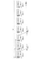
Eighth embodiment
Furthermore, an eighth embodiment of the present invention will be described with reference to FIG. In the MRI apparatus of this embodiment, the nesting method of the scanning method described in the seventh embodiment is changed to another mode, that is, “interleave mode”.
[0108]
In the MRI apparatus of this embodiment, the configuration and functions other than this mode are the same as or similar to those of the seventh embodiment.
[0109]
According to this interleave mode nesting method, as shown in FIG. 14, first, the inversion pulse Inv1 is applied to the first imaging slice Aima-1, and after a predetermined time, the inversion pulse Inv4 has already been applied. The saturation sequence SQsat-4 is executed for the pre-saturation slice Apre-4 for the imaging slice Aima-4, and the data acquisition sequence SQacq-4 is executed for the imaging slice Aima-4.
[0110]
After this predetermined time, an inversion pulse Inv3 is applied to the third imaging slice Aima-3. Thereafter, the saturation sequence SQsat-6 is executed for the pre-saturation slice Apre-6 for the imaging slice Aima-6 to which the inversion pulse Inv6 has already been applied after a predetermined time, and further, the imaging slice Aima-6 The data collection sequence SQacq-6 is executed.
[0111]
Further, an inversion pulse Inv5 is applied to the fifth imaging slice Aima-5 after a predetermined time. Further again, after a predetermined time, the saturation sequence SQsat-1 is executed on the pre-saturation slice Apre-1 for the imaging slice Aima-1 to which the inversion pulse Inv1 is applied, and after the predetermined time, the imaging slice Aima-1 The data collection sequence SQacq-1 is executed.
[0112]
Then, after a predetermined time again, the inversion pulse Inv7 is applied to the seventh imaging slice Aima-7. Thereafter, pulse application and MR signal acquisition are performed in the same manner. Finally, the data acquisition sequence SQacq-2 is executed on the second imaging slice Aima-2, and the repetition time TR is completed.
[0113]
As described above, since the imaging slices are selected every other frame as 4, 6, 1, 5, 7 while being a multi-slice sequence using the same high-speed FLAIR method, in addition to the effects of the seventh embodiment, There is a further advantage that the image quality can be improved by more reliably eliminating the spin interference.
[0114]
In each of the above embodiments, a description has been given centering on an example in which a plurality of saturation pulses are applied to a slice (pre-saturation slice) set on the arterial inflow side of an imaging slice, but the present invention is not necessarily limited to this. is not. A plurality of saturation pulses may be applied to a slice set in the arterial outflow side (venous inflow side) of the imaging slice (in the case of FIG. 3, the lower side of the imaging slice Aima in the drawing). In that case, the magnitude relationship between the signal values of the arteriovenous cells is reversed, but an MRA image with a high contrast between the substantial part and the blood flow in which the arterial veins are well separated can be obtained non-invasively.
[0115]
In each of the above embodiments, the spoiler pulse may be applied only in any one direction or two directions.
[0116]
【The invention's effect】
As described above, according to the MR angiography data collection method and MRI apparatus of the present invention,
A pre-sequence including a plurality of saturation pulses for saturating nuclear spins in the blood flow is sequentially applied to the same slice of a subject different from the imaging slice in time series, for example, the pre-sequence includes a plurality of saturation pulses. One for blood flow spin dispersion to be applied after application of the last saturation pulse in time series among a plurality of saturation pulses including a spoiler pulse for blood flow spin dispersion applied after each application of the pulse 1) An MRA image in which arterial or venous signals can be reliably suppressed even if the blood flow velocity is too fast or too slow, and the arterial vein is visually separated. 2) By applying a plurality of saturation pulses to the same surface, a large MT effect is caused in the stationary substantial part of the imaging slice, and the flowing blood The MT effect of can be kept small, and the function of only one saturation pulse can be given to the blood flow to be saturated (arteries or veins), thereby providing a high blood flow / substantial contrast and excellent visibility. MRA images can be provided 3) in a non-invasive state without using a contrast agent.
[Brief description of the drawings]
FIG. 1 is a block diagram showing an example of an MRI apparatus according to an embodiment of the present invention.
FIG. 2 is a diagram showing an example of a scan sequence according to the first embodiment.
FIG. 3 is a view for explaining an example of an imaging slice, a pre-saturated slice, and a blood flow running state according to the first embodiment.
FIG. 4 is a diagram schematically showing an example of an MRA image obtained in the first embodiment.
FIG. 5 is a diagram showing an example of a scan sequence according to the second embodiment.
FIG. 6 is a diagram showing an example of a scan sequence according to the third embodiment.
FIG. 7 is a diagram for explaining a change in MT effect with a change in flip angle.
FIG. 8 is a diagram showing an example of a scan sequence according to the fourth embodiment.
FIG. 9 is a diagram showing an example of a scan sequence according to the fifth embodiment.
FIG. 10 is a diagram showing an example of a single slice scan sequence using the high-speed FLAIR method according to the sixth embodiment.
FIG. 11 is a diagram showing an entire multi-slice scan sequence using the high-speed FLAIR method according to the seventh embodiment.
FIG. 12 is a diagram clarifying a correspondence relationship between a scan sequence and a slice position according to the seventh embodiment.
13 is a pulse train diagram showing in detail the first part of the scan sequence of FIG.
FIG. 14 is a diagram showing an entire multi-slice scan sequence using the high-speed FLAIR method according to the eighth embodiment.
[Explanation of symbols]
1 Magnet
2 Static magnetic field power supply
3 Gradient magnetic field coil unit
4 Gradient magnetic field power supply
5 Sequencer
6 Controller
7 RF coil
8T transmitter
8R receiver
10 Arithmetic unit
11 Storage unit
12 Display
13 Input device
Claims (18)
前記被検体内の前記撮像スライスとは異なる位置に設定した飽和スライスに時系列的に印加する複数個の飽和パルスを含む事前シーケンスを実行し、前記事前シーケンスは、所要の反転時間を利用して、複数個の飽和パルスであるサチュレーションパルス列を印加し、サチュレーションパルス列の最後尾の飽和パルスの印加後のみにスポイラーパルスを印加するサチュレーションシーケンスを実行する第1の実行手段と、
前記事前シーケンスの実行後に、前記撮影スライスからMR信号を収集するデータ収集シーケンスを実行する第2の実行手段と、
前記MR信号に基づき前記血流像を生成する画像生成手段とを備えることを特徴とするMRI装置。In an MRI apparatus for obtaining a blood flow image of an imaging slice of a subject,
A pre-sequence including a plurality of saturation pulses applied in time series to a saturation slice set at a position different from the imaging slice in the subject is executed, and the pre-sequence uses a required inversion time. Applying a saturation pulse train that is a plurality of saturation pulses and applying a spoiler pulse only after the last saturation pulse of the saturation pulse train is applied ;
Second execution means for executing a data acquisition sequence for acquiring MR signals from the imaging slice after execution of the pre-sequence;
An MRI apparatus comprising image generation means for generating the blood flow image based on the MR signal.
前記スライス用傾斜磁場パルスは、前記複数個の飽和パルスのそれぞれと並行して印加される複数のパルスから成るMRI装置。In the invention of claim 2,
The slice gradient magnetic field pulse is an MRI apparatus comprising a plurality of pulses applied in parallel with each of the plurality of saturation pulses.
前記複数個の飽和パルスは、その隣り合う飽和パルス同士間の空き時間間隔を零に設定して時系列に並べたパルス列であるMRI装置。In the invention of claim 3,
The MRI apparatus, wherein the plurality of saturation pulses are pulse trains arranged in chronological order with an empty time interval between adjacent saturation pulses set to zero.
前記スライス用傾斜磁場パルスは、前記複数個の飽和パルス全体と並行して印加される1個のパルスから成るMRI装置。In the invention of claim 2,
The slice gradient magnetic field pulse is an MRI apparatus comprising one pulse applied in parallel with all of the plurality of saturation pulses.
前記事前シーケンスは、前記複数個の飽和パルスの印加後に印加するスライス方向、読出し方向および位相エコー方向の傾斜磁場スポイラーパルスを含むMRI装置。In the invention of claim 2,
The MRI apparatus, wherein the pre-sequence includes gradient magnetic field spoiler pulses in a slice direction, a readout direction, and a phase echo direction applied after application of the plurality of saturation pulses .
前記スポイラーパルスは、前記スライス方向に印加する傾斜磁場スポイラーパルスを少なくとも含むMRI装置。In the invention of claim 1,
The MRI apparatus, wherein the spoiler pulse includes at least a gradient magnetic field spoiler pulse applied in the slice direction.
前記スポイラーパルスは、前記スライス方向とこれに直交する位相エンコード方向および読出し方向との3方向それぞれに印加する傾斜磁場スポイラーパルスを含むMRI装置。In the invention of claim 1,
The MRI apparatus includes a gradient magnetic field spoiler pulse that is applied in each of three directions of the slice direction, a phase encoding direction orthogonal to the slice direction, and a reading direction.
前記複数個の飽和パルスのそれぞれが前記スピンに与えるフリップ角は全て同一で100°以下の値であるMRI装置。In the invention of claim 2,
An MRI apparatus in which each of the plurality of saturation pulses has the same flip angle given to the spin and is a value of 100 ° or less.
前記複数個の飽和パルスのそれぞれが前記スピンに与えるフリップ角は、その少なくとも一個の飽和パルスと残りの飽和パルスとでは異なる値に設定されているMRI装置。In the invention of claim 2,
The MRI apparatus in which the flip angle that each of the plurality of saturation pulses gives to the spin is set to a different value for at least one saturation pulse and the remaining saturation pulses.
前記複数個の飽和パルスのそれぞれは前記フリップ角度が互いに異なるように設定されているMRI装置。In the invention of claim 10,
The MRI apparatus, wherein each of the plurality of saturation pulses is set so that the flip angles are different from each other.
前記複数個の飽和パルスのそれぞれのフリップ角度は、時系列の時間的後ろに至る飽和パルスになるほど低下する値であるMRI装置。In the invention of claim 11,
An MRI apparatus in which the flip angle of each of the plurality of saturation pulses is a value that decreases as the saturation pulse reaches the back of the time series.
前記スライス用傾斜磁場は、前記飽和スライスと前記撮影スライスとが略平行になるように設定されているMRI装置。In the invention of claim 2,
The MRI apparatus in which the gradient magnetic field for slice is set so that the saturated slice and the imaging slice are substantially parallel.
前記データ収集シーケンスは、高速FLAIR法の一部を成すインバージョンパルスの印加後の所定反転時間に実行される当該高速FLAIR法の残りの部分を成す高速SE系列に基づくパルス列であるMRI装置。In the invention of claim 2,
The MRI apparatus, wherein the data acquisition sequence is a pulse train based on a high-speed SE sequence that forms the remaining part of the high-speed FLAIR method that is executed at a predetermined inversion time after application of an inversion pulse that forms a part of the high-speed FLAIR method.
前記第1の実行手段は、前記インバージョンパルスと前記高速SE系列に基づくパルス列との間の前記反転時間の間に前記事前シーケンスを実行する手段であるMRI装置。In the invention of claim 14,
The first execution means is means for executing the pre-sequence during the inversion time between the inversion pulse and the pulse train based on the fast SE sequence.
前記第1の実行手段はマルチスライス法に基づいて前記事前シーケンスを複数回繰り返す手段であり、かつ、前記第2の実行手段はそのマルチスライス法に基づいて前記データ収集シーケンスをその事前シーケンスの繰り返し回数と同数の複数回繰り返す手段であるMRI装置。In the invention of claim 15,
The first execution means is means for repeating the pre-sequence a plurality of times based on a multi-slice method, and the second execution means converts the data acquisition sequence based on the multi-slice method to the pre-sequence An MRI apparatus that is a means for repeating the same number of repetitions a plurality of times.
前記第1の実行手段および第2の実行手段は、前記マルチスライス法に拠る複数枚の前記撮像スライスに対して時系列に入れ子方式で前記事前シーケンスおよび前記データ収集シーケンスを繰り返す手段であるMRI装置。In the invention of claim 16,
The first execution means and the second execution means are means for repeating the pre-sequence and the data collection sequence in a time series nesting manner with respect to a plurality of the imaging slices based on the multi-slice method. apparatus.
前記被検体が存在する空間に静磁場を発生する磁石と、
前記静磁場にスライス用、位相エンコード用、および読出し用の傾斜磁場を重畳する傾斜磁場コイルと、
この傾斜磁場コイルに前記傾斜磁場を発生させるパルス電流を供給する傾斜磁場発生ユニットと、
前記被検体にスピン励起用の高周波信号を送信するとともに当該被検体で発生したMR信号を受信するRFコイルと、
このRFコイルを介して前記高周波信号を送信するとともに前記MR信号を受信する送受信ユニットと、
この送受信ユニットで受信された前記MR信号に基づき前記血流像を再構成する再構成ユニットと、
前記傾斜磁場発生ユニットおよび前記送受信ユニットを制御して所望のスキャンシーケンスを実行するシーケンサとを備え、
前記スキャンシーケンスは、前記被検体内の前記撮像スライスとは異なる位置に設定された飽和スライスに複数個の飽和パルスを含む事前シーケンスと、この事前シーケンスに続いて印加するMR信号収集用のデータ収集シーケンスとからなり、
前記事前シーケンスは、所要の反転時間を利用して、複数個の飽和パルスであるサチュレーションパルス列を印加し、サチュレーションパルス列の最後尾の飽和パルスの印加後のみにスポイラーパルスを印加し、且つ当該飽和スライスを選択するスライス用傾斜磁場パルスを当該複数個の飽和パルスと並行して印加し、この複数個の飽和パルスと前記スライス用傾斜磁場パルスの印加後に、前記撮影スライスからMR信号を収集するデータ収集シーケンスのパルス列を印加するアルゴリズムに基づくシーケンスであることを特徴とするMRI装置。In an MRI apparatus for obtaining a blood flow image of an imaging slice of a subject,
A magnet that generates a static magnetic field in a space where the subject exists;
A gradient coil that superimposes gradient magnetic fields for slicing, phase encoding, and reading on the static magnetic field;
A gradient magnetic field generating unit for supplying a pulse current for generating the gradient magnetic field to the gradient magnetic field coil;
An RF coil that transmits a high-frequency signal for spin excitation to the subject and receives an MR signal generated in the subject;
A transmission / reception unit for transmitting the high-frequency signal and receiving the MR signal via the RF coil;
A reconstruction unit for reconstructing the blood flow image based on the MR signal received by the transceiver unit;
A sequencer for controlling the gradient magnetic field generation unit and the transmission / reception unit to execute a desired scan sequence;
The scan sequence includes a pre-sequence including a plurality of saturation pulses in a saturation slice set at a position different from the imaging slice in the subject , and data acquisition for MR signal collection applied subsequent to the pre-sequence. A sequence and
The pre-sequence applies a saturation pulse train, which is a plurality of saturation pulses, using a required inversion time, applies a spoiler pulse only after applying the last saturation pulse of the saturation pulse train , and Data for collecting MR signals from the imaging slice after applying the gradient magnetic field pulses for selecting a slice in parallel with the plurality of saturation pulses and applying the plurality of saturation pulses and the gradient magnetic field pulses for slices An MRI apparatus, which is a sequence based on an algorithm that applies a pulse train of an acquisition sequence.
Priority Applications (2)
| Application Number | Priority Date | Filing Date | Title |
|---|---|---|---|
| JP07094198A JP4040742B2 (en) | 1997-03-28 | 1998-03-19 | MRI equipment |
| US09/048,290 US6320377B1 (en) | 1997-03-28 | 1998-03-26 | MR imaging with pre-sequence including plural saturation pulses |
Applications Claiming Priority (3)
| Application Number | Priority Date | Filing Date | Title |
|---|---|---|---|
| JP9-78559 | 1997-03-28 | ||
| JP7855997 | 1997-03-28 | ||
| JP07094198A JP4040742B2 (en) | 1997-03-28 | 1998-03-19 | MRI equipment |
Publications (2)
| Publication Number | Publication Date |
|---|---|
| JPH10323336A JPH10323336A (en) | 1998-12-08 |
| JP4040742B2 true JP4040742B2 (en) | 2008-01-30 |
Family
ID=26412058
Family Applications (1)
| Application Number | Title | Priority Date | Filing Date |
|---|---|---|---|
| JP07094198A Expired - Lifetime JP4040742B2 (en) | 1997-03-28 | 1998-03-19 | MRI equipment |
Country Status (2)
| Country | Link |
|---|---|
| US (1) | US6320377B1 (en) |
| JP (1) | JP4040742B2 (en) |
Families Citing this family (63)
| Publication number | Priority date | Publication date | Assignee | Title |
|---|---|---|---|---|
| US6850793B1 (en) * | 1995-03-20 | 2005-02-01 | Kabushiki Kaisha Toshiba | MR imaging using nested pulse sequence involving IR pulse |
| JP4082779B2 (en) * | 1998-04-17 | 2008-04-30 | 株式会社東芝 | MRI equipment |
| US7254437B2 (en) * | 1998-04-17 | 2007-08-07 | Kabushiki Kaisha Toshiba | MR imaging providing tissue/blood contrast image |
| JP4334049B2 (en) * | 1999-02-26 | 2009-09-16 | 株式会社東芝 | MRI equipment |
| DE19928110A1 (en) * | 1999-06-19 | 2000-12-21 | Philips Corp Intellectual Pty | MR procedure |
| JP2001000415A (en) * | 1999-06-24 | 2001-01-09 | Ge Yokogawa Medical Systems Ltd | Gradient magnetic field application method and device and magnetic resonance imaging device |
| JP4357641B2 (en) * | 1999-06-29 | 2009-11-04 | 株式会社東芝 | MRI equipment |
| US6618605B1 (en) * | 1999-09-08 | 2003-09-09 | General Electric Company | Method and apparatus for MR perfusion image acquisition using a notched RF saturation pulse |
| US6801800B2 (en) * | 1999-11-29 | 2004-10-05 | Kabushiki Kaisha Toshiba | MR imaging using ECG-prep scan |
| JP4632535B2 (en) | 2000-12-27 | 2011-02-16 | 株式会社東芝 | MRI equipment |
| JP4451528B2 (en) * | 1999-12-24 | 2010-04-14 | Geヘルスケア・ジャパン株式会社 | Magnetic resonance imaging device |
| US6583623B1 (en) * | 2000-03-31 | 2003-06-24 | University Of Rochester | Interleaved water and fat dual-echo spin echo magnetic resonance imaging with intrinsic chemical shift elimination |
| JP2002248092A (en) * | 2000-12-22 | 2002-09-03 | Toshiba Corp | Magnetic resonance imaging apparatus and magnetic resonance imaging method |
| DE10133278A1 (en) * | 2001-07-09 | 2003-01-23 | Univ Eberhard Karls | Displaying fluid perfusion process involves nuclear spin resonance; transition region between preparation zone and measurement zone has structure that increases surface area |
| JP2003038456A (en) * | 2001-07-10 | 2003-02-12 | Ge Medical Systems Global Technology Co Llc | Spin excitation method, magnetic resonance photographing method and magnetic resonance photographing device |
| JP5002099B2 (en) | 2001-08-31 | 2012-08-15 | 株式会社東芝 | Magnetic resonance imaging system |
| US6628116B1 (en) * | 2001-09-06 | 2003-09-30 | Ge Medical Systems Global Technology Co., Llc | Process and apparatus to remove stimulated echo artifacts caused by interactions of a preparation sequence with a gradient echo sequence in MR imaging |
| US7047062B2 (en) * | 2002-05-16 | 2006-05-16 | Ge Medical Systems Global Technology Company, Llc | Magnetic resonance imaging with nested gradient pulses |
| US7034530B2 (en) * | 2002-06-28 | 2006-04-25 | General Electric Company | Technique for simultaneous acquisition of multiple independent MR imaging volumes with optimization of magnetic field homogeneity for spin preparation |
| JP4309632B2 (en) * | 2002-10-08 | 2009-08-05 | 株式会社東芝 | Magnetic resonance imaging system |
| US7627359B2 (en) * | 2002-12-19 | 2009-12-01 | University Of Washington | Quantitative contrast enhanced black-blood imaging using quadruple-inversion recovery |
| US7715900B2 (en) * | 2002-12-19 | 2010-05-11 | University Of Washington | Quadruple inversion recovery for quantitative contrast-enhanced black blood imaging |
| US8010179B2 (en) * | 2003-09-25 | 2011-08-30 | General Electric Company | Method and apparatus of gradient echo imaging with on-the-fly optimization of tissue suppression |
| DE102004022687B4 (en) * | 2004-05-05 | 2012-01-05 | Bruker Biospin Gmbh | Time-domain method for quantitatively determining the content of at least one component of a sample by means of a low-resolution nuclear magnetic resonance spectrometer |
| JP4717573B2 (en) * | 2005-09-26 | 2011-07-06 | ジーイー・メディカル・システムズ・グローバル・テクノロジー・カンパニー・エルエルシー | MRI equipment |
| JP5288745B2 (en) * | 2006-09-13 | 2013-09-11 | 株式会社東芝 | Magnetic resonance imaging system |
| KR100852402B1 (en) * | 2006-12-21 | 2008-08-14 | 한국과학기술원 | Nonlinear Phase Correction Method. |
| JP5022696B2 (en) * | 2006-12-22 | 2012-09-12 | ジーイー・メディカル・システムズ・グローバル・テクノロジー・カンパニー・エルエルシー | Magnetic resonance imaging system |
| US8457711B2 (en) * | 2007-02-01 | 2013-06-04 | Beth Israel Deaconess Medical Center, Inc. | Magnetic resonance imaging of coronary venous structures |
| JP5398149B2 (en) * | 2007-03-27 | 2014-01-29 | 株式会社東芝 | Magnetic resonance imaging system |
| US8369599B2 (en) * | 2007-05-17 | 2013-02-05 | University Of Washington | Fast two-point mapping of the bound pool fraction and cross-relaxation rate constant for MRI |
| US8649846B2 (en) | 2007-07-11 | 2014-02-11 | Kabushiki Kaisha Toshiba | Magnetic resonance imaging apparatus and magnetic resonance imaging method |
| JP5433169B2 (en) * | 2007-07-11 | 2014-03-05 | 株式会社東芝 | Magnetic resonance imaging system |
| WO2009063791A1 (en) * | 2007-11-16 | 2009-05-22 | Hitachi Medical Corporation | Magnetic resonance imaging device and blood vessel imaging method |
| US8320647B2 (en) | 2007-11-20 | 2012-11-27 | Olea Medical | Method and system for processing multiple series of biological images obtained from a patient |
| JP5383036B2 (en) * | 2007-12-28 | 2014-01-08 | ジーイー・メディカル・システムズ・グローバル・テクノロジー・カンパニー・エルエルシー | MRI equipment |
| US9448296B2 (en) * | 2008-03-18 | 2016-09-20 | University Of Washington | Motion-sensitized driven equilibrium blood-suppression sequence for vessel wall imaging |
| JP2009254629A (en) * | 2008-04-17 | 2009-11-05 | Toshiba Corp | Magnetic resonance imaging apparatus |
| US8169218B2 (en) * | 2008-04-18 | 2012-05-01 | Beth Israel Deaconess Medical Center, Inc. | Methods and apparatus for non-contrast enhanced pulmonary magnetic resonance imaging |
| JP5305785B2 (en) * | 2008-08-25 | 2013-10-02 | ジーイー・メディカル・システムズ・グローバル・テクノロジー・カンパニー・エルエルシー | Magnetic resonance imaging apparatus and method for controlling magnetic resonance imaging apparatus |
| WO2010057093A2 (en) * | 2008-11-14 | 2010-05-20 | University Of Southern California | Tailored radiofrequency pulses for uniform saturation in magnetic resonance imaging |
| US9211081B2 (en) * | 2009-04-16 | 2015-12-15 | Ghost Medical Technologies, Ltd | Method for non-contrast enhanced magnetic resonance angiography |
| US9176212B2 (en) * | 2009-04-16 | 2015-11-03 | Ghost Medical Technologies, Ltd | Method for non-contrast enhanced magnetic resonance angiography |
| JP5564213B2 (en) * | 2009-08-12 | 2014-07-30 | 株式会社日立メディコ | Magnetic resonance imaging system |
| US8723516B2 (en) | 2010-02-26 | 2014-05-13 | Kabushiki Kaisha Toshiba | B1-robust and T1-robust species suppression in MRI |
| DE102010003895B4 (en) | 2010-04-13 | 2019-07-04 | Siemens Healthcare Gmbh | Method for generating angiographic magnetic resonance images |
| CN103890602B (en) * | 2011-09-09 | 2016-08-17 | 阿尔琼·阿鲁纳恰拉姆 | Method and system for rapid MRI acquisition (RATE) using custom signal excitation modules |
| US9687172B2 (en) * | 2012-01-24 | 2017-06-27 | National Institute of Health (NIH), The United States of America, U.S. Dept. of Health and Human Services (DHHS) | System for motion corrected MR diffusion imaging |
| US10405772B2 (en) * | 2012-09-18 | 2019-09-10 | Wisconsin Alumni Research Foundation, Inc. | Magnetic resonance angiography and venography |
| US9507003B2 (en) | 2012-09-19 | 2016-11-29 | Northshore University Healthsystem | System and method for imaging of vascular structures using non-contrast enhanced magnetic resonance imaging |
| US9889318B2 (en) | 2012-10-26 | 2018-02-13 | Viewray Technologies, Inc. | Assessment and improvement of treatment using imaging of physiological responses to radiation therapy |
| JP6552789B2 (en) * | 2013-04-04 | 2019-07-31 | キヤノンメディカルシステムズ株式会社 | Magnetic resonance imaging system |
| US9241654B2 (en) | 2013-06-20 | 2016-01-26 | Northshore University Healthsystem | System and method for selective magnetic resonance imaging angiography of arteries or veins |
| US10026186B2 (en) | 2013-12-03 | 2018-07-17 | Viewray Technologies, Inc. | Single- and multi-modality alignment of medical images in the presence of non-rigid deformations using phase correlation |
| US9638781B2 (en) * | 2014-02-03 | 2017-05-02 | Toshiba Medical Systems Corporation | Enhancement of MT effect and/or CEST effect |
| US9498139B2 (en) * | 2014-02-03 | 2016-11-22 | Toshiba Medical Systems Corporation | Background suppression by time dependent flip angle of saturation pulses |
| EP3423153B1 (en) | 2016-03-02 | 2021-05-19 | ViewRay Technologies, Inc. | Particle therapy with magnetic resonance imaging |
| US11378629B2 (en) * | 2016-06-22 | 2022-07-05 | Viewray Technologies, Inc. | Magnetic resonance imaging |
| US11284811B2 (en) | 2016-06-22 | 2022-03-29 | Viewray Technologies, Inc. | Magnetic resonance volumetric imaging |
| CN107773233B (en) * | 2016-08-31 | 2020-09-15 | 上海联影医疗科技有限公司 | Magnetic resonance imaging method and device |
| CN108209918B (en) * | 2017-12-30 | 2021-09-07 | 上海联影医疗科技股份有限公司 | Magnetic resonance imaging method and magnetic resonance system |
| US11209509B2 (en) | 2018-05-16 | 2021-12-28 | Viewray Technologies, Inc. | Resistive electromagnet systems and methods |
| DE102020206515A1 (en) | 2020-05-26 | 2021-12-02 | Siemens Healthcare Gmbh | Saturation-prepared recording of MR image data |
Family Cites Families (8)
| Publication number | Priority date | Publication date | Assignee | Title |
|---|---|---|---|---|
| US4715383B1 (en) * | 1986-11-10 | 1995-10-31 | Mayo Medical Resources | Method for reducing artifacts in NMR images |
| US5034694A (en) * | 1989-11-22 | 1991-07-23 | Picker International, Inc. | Minimum basis set MR angiography |
| US5273040A (en) * | 1991-11-14 | 1993-12-28 | Picker International, Inc. | Measurement of vetricle volumes with cardiac MRI |
| DE4337503C1 (en) * | 1993-11-03 | 1995-02-09 | Siemens Ag | Method for spatially resolved blood-flow measurement by means of nuclear magnetic resonance |
| US5528144A (en) * | 1994-07-29 | 1996-06-18 | Picker International, Inc. | Interleaved slab inversion for enhanced throughput in fluid attenuated inversion recovery imaging |
| US5677628A (en) * | 1995-03-15 | 1997-10-14 | Kabushiki Kaisha Toshiba | Magnetic resonance diagnostic apparatus |
| US5633586A (en) * | 1996-02-29 | 1997-05-27 | Siemens Medical Systems, Inc. | Rapid fat- or water-suppressed multislice MR pulse sequence including initial prepulse |
| US6043655A (en) * | 1997-01-09 | 2000-03-28 | Kabushiki Kaisha Toshiba | MR imaging utilizing the time of flight effect |
-
1998
- 1998-03-19 JP JP07094198A patent/JP4040742B2/en not_active Expired - Lifetime
- 1998-03-26 US US09/048,290 patent/US6320377B1/en not_active Expired - Lifetime
Also Published As
| Publication number | Publication date |
|---|---|
| JPH10323336A (en) | 1998-12-08 |
| US6320377B1 (en) | 2001-11-20 |
Similar Documents
| Publication | Publication Date | Title |
|---|---|---|
| JP4040742B2 (en) | MRI equipment | |
| JP4309632B2 (en) | Magnetic resonance imaging system | |
| CN100457028C (en) | Magnetic resonance imaging with pulse sequence optimization using pre-scan | |
| JP5366370B2 (en) | Magnetic resonance imaging system | |
| JP4594482B2 (en) | Magnetic resonance imaging method and magnetic resonance imaging apparatus | |
| US20140046168A1 (en) | Magnetic resonance imaging system | |
| JP3995542B2 (en) | Magnetic resonance imaging apparatus and magnetic resonance imaging data collection method | |
| JP2008093418A (en) | Magnetic resonance imaging apparatus and control method thereof | |
| JP2002200054A (en) | MRI apparatus and MR imaging method | |
| US5159550A (en) | Artifact suppression system for magnetic resonnance imaging apparatus | |
| JP4082779B2 (en) | MRI equipment | |
| JP4253526B2 (en) | Magnetic resonance imaging system | |
| JP4413304B2 (en) | MRI equipment | |
| JP2001178701A (en) | MRI apparatus and MR imaging method | |
| JP3434816B2 (en) | MRI equipment | |
| JP5643789B2 (en) | Magnetic resonance imaging system | |
| JP4225648B2 (en) | MRI equipment | |
| JP5175420B2 (en) | MRI apparatus and MR imaging method | |
| JP4777372B2 (en) | Magnetic resonance imaging system | |
| JP2009160052A (en) | Magnetic resonance imaging system | |
| JP4538081B2 (en) | MRI equipment | |
| JP5159836B2 (en) | MRI equipment | |
| JPH10248825A (en) | MRI apparatus and MR imaging method | |
| JP5380585B2 (en) | MRI equipment | |
| JP4357641B2 (en) | MRI equipment |
Legal Events
| Date | Code | Title | Description |
|---|---|---|---|
| A621 | Written request for application examination |
Free format text: JAPANESE INTERMEDIATE CODE: A621 Effective date: 20050310 |
|
| A977 | Report on retrieval |
Free format text: JAPANESE INTERMEDIATE CODE: A971007 Effective date: 20070220 |
|
| A131 | Notification of reasons for refusal |
Free format text: JAPANESE INTERMEDIATE CODE: A131 Effective date: 20070306 |
|
| A521 | Request for written amendment filed |
Free format text: JAPANESE INTERMEDIATE CODE: A523 Effective date: 20070427 |
|
| A02 | Decision of refusal |
Free format text: JAPANESE INTERMEDIATE CODE: A02 Effective date: 20070731 |
|
| A521 | Request for written amendment filed |
Free format text: JAPANESE INTERMEDIATE CODE: A523 Effective date: 20070925 |
|
| A911 | Transfer to examiner for re-examination before appeal (zenchi) |
Free format text: JAPANESE INTERMEDIATE CODE: A911 Effective date: 20071009 |
|
| TRDD | Decision of grant or rejection written | ||
| A01 | Written decision to grant a patent or to grant a registration (utility model) |
Free format text: JAPANESE INTERMEDIATE CODE: A01 Effective date: 20071106 |
|
| A61 | First payment of annual fees (during grant procedure) |
Free format text: JAPANESE INTERMEDIATE CODE: A61 Effective date: 20071108 |
|
| FPAY | Renewal fee payment (event date is renewal date of database) |
Free format text: PAYMENT UNTIL: 20101116 Year of fee payment: 3 |
|
| FPAY | Renewal fee payment (event date is renewal date of database) |
Free format text: PAYMENT UNTIL: 20101116 Year of fee payment: 3 |
|
| FPAY | Renewal fee payment (event date is renewal date of database) |
Free format text: PAYMENT UNTIL: 20101116 Year of fee payment: 3 |
|
| FPAY | Renewal fee payment (event date is renewal date of database) |
Free format text: PAYMENT UNTIL: 20111116 Year of fee payment: 4 |
|
| FPAY | Renewal fee payment (event date is renewal date of database) |
Free format text: PAYMENT UNTIL: 20111116 Year of fee payment: 4 |
|
| FPAY | Renewal fee payment (event date is renewal date of database) |
Free format text: PAYMENT UNTIL: 20121116 Year of fee payment: 5 |
|
| FPAY | Renewal fee payment (event date is renewal date of database) |
Free format text: PAYMENT UNTIL: 20131116 Year of fee payment: 6 |
|
| S111 | Request for change of ownership or part of ownership |
Free format text: JAPANESE INTERMEDIATE CODE: R313114 Free format text: JAPANESE INTERMEDIATE CODE: R313117 Free format text: JAPANESE INTERMEDIATE CODE: R313111 |
|
| R371 | Transfer withdrawn |
Free format text: JAPANESE INTERMEDIATE CODE: R371 |
|
| S111 | Request for change of ownership or part of ownership |
Free format text: JAPANESE INTERMEDIATE CODE: R313111 Free format text: JAPANESE INTERMEDIATE CODE: R313117 Free format text: JAPANESE INTERMEDIATE CODE: R313114 |
|
| R350 | Written notification of registration of transfer |
Free format text: JAPANESE INTERMEDIATE CODE: R350 |
|
| EXPY | Cancellation because of completion of term |