JP4591128B2 - Method for producing porous carbon plate - Google Patents
Method for producing porous carbon plate Download PDFInfo
- Publication number
- JP4591128B2 JP4591128B2 JP2005067711A JP2005067711A JP4591128B2 JP 4591128 B2 JP4591128 B2 JP 4591128B2 JP 2005067711 A JP2005067711 A JP 2005067711A JP 2005067711 A JP2005067711 A JP 2005067711A JP 4591128 B2 JP4591128 B2 JP 4591128B2
- Authority
- JP
- Japan
- Prior art keywords
- carbon fiber
- thermosetting resin
- carbon
- resin
- porous carbon
- Prior art date
- Legal status (The legal status is an assumption and is not a legal conclusion. Google has not performed a legal analysis and makes no representation as to the accuracy of the status listed.)
- Expired - Lifetime
Links
Images

Classifications
-
- Y—GENERAL TAGGING OF NEW TECHNOLOGICAL DEVELOPMENTS; GENERAL TAGGING OF CROSS-SECTIONAL TECHNOLOGIES SPANNING OVER SEVERAL SECTIONS OF THE IPC; TECHNICAL SUBJECTS COVERED BY FORMER USPC CROSS-REFERENCE ART COLLECTIONS [XRACs] AND DIGESTS
- Y02—TECHNOLOGIES OR APPLICATIONS FOR MITIGATION OR ADAPTATION AGAINST CLIMATE CHANGE
- Y02E—REDUCTION OF GREENHOUSE GAS [GHG] EMISSIONS, RELATED TO ENERGY GENERATION, TRANSMISSION OR DISTRIBUTION
- Y02E60/00—Enabling technologies; Technologies with a potential or indirect contribution to GHG emissions mitigation
- Y02E60/30—Hydrogen technology
- Y02E60/50—Fuel cells
-
- Y—GENERAL TAGGING OF NEW TECHNOLOGICAL DEVELOPMENTS; GENERAL TAGGING OF CROSS-SECTIONAL TECHNOLOGIES SPANNING OVER SEVERAL SECTIONS OF THE IPC; TECHNICAL SUBJECTS COVERED BY FORMER USPC CROSS-REFERENCE ART COLLECTIONS [XRACs] AND DIGESTS
- Y02—TECHNOLOGIES OR APPLICATIONS FOR MITIGATION OR ADAPTATION AGAINST CLIMATE CHANGE
- Y02P—CLIMATE CHANGE MITIGATION TECHNOLOGIES IN THE PRODUCTION OR PROCESSING OF GOODS
- Y02P70/00—Climate change mitigation technologies in the production process for final industrial or consumer products
- Y02P70/50—Manufacturing or production processes characterised by the final manufactured product
Landscapes
- Moulding By Coating Moulds (AREA)
- Paper (AREA)
- Inert Electrodes (AREA)
- Fuel Cell (AREA)
Description
本発明は、燃料電池、特に固体高分子型燃料電池のガス拡散体を構成するのに好適な多孔質炭素板の中間基材となる炭素繊維シートから得られる多孔質炭素板の製造方法に関する。 The present invention relates to a fuel cell, in particular method of producing a carbon fiber sheet or we obtained a porous carbon plate comprising an intermediate base material of suitable porous carbon plate for constituting the gas diffuser of a solid polymer electrolyte fuel cell About.
固体高分子型燃料電池電極のガス拡散体には、導電性が高いこと、機械的強度が高いこと、好適な気体透過性を持つことなどの特性が要求される。このような燃料電池電極のガス拡散体の材料としては、炭素短繊維が炭素で結着された多孔質炭素板、炭素繊維織物、炭素繊維不織布などがある。例えば炭素短繊維が炭素で結着された多孔質炭素板を得る方法としては、抄造によって得た炭素短繊維が実質的に二次元ランダムな方向に分散した炭素繊維集合体にレゾール型フェノール樹脂とノボラック型フェノール樹脂を所定の比率で混合した樹脂を含浸して二枚もしくは四枚重ねて乾燥あるいは加熱加圧して炭素繊維シートからなる中間基材を得、この中間基材を加熱し樹脂を炭素化して多孔質炭素板を得ている(例えば特許文献1)。 The gas diffuser of the polymer electrolyte fuel cell electrode is required to have characteristics such as high conductivity, high mechanical strength, and suitable gas permeability. Examples of the material for the gas diffuser of the fuel cell electrode include a porous carbon plate in which short carbon fibers are bound with carbon, a carbon fiber woven fabric, and a carbon fiber non-woven fabric. For example, as a method for obtaining a porous carbon plate in which short carbon fibers are bound with carbon, a resol type phenolic resin and a carbon fiber aggregate in which short carbon fibers obtained by papermaking are dispersed in a substantially two-dimensional random direction are used. Impregnated with a resin mixed with a novolac type phenol resin at a predetermined ratio, two or four sheets are stacked and dried or heated and pressed to obtain an intermediate substrate made of a carbon fiber sheet, and the intermediate substrate is heated to convert the resin into carbon To obtain a porous carbon plate (for example, Patent Document 1).
この多孔質炭素板は、曲げ強さが14.7MPa以上、厚さ方向の圧縮強さが0.49MPa以上、厚さ方向の比抵抗が0.01Ωmと、機械的強度、導電性を高く保ちながら、厚さ方向の気体透過性が3000ml・mm/cm2 /hr/mmAq以上と高い気体透過性を持った多孔質炭素板が得られるとしている。 This porous carbon plate maintains a high mechanical strength and electrical conductivity with a bending strength of 14.7 MPa or more, a compressive strength in the thickness direction of 0.49 MPa or more, and a specific resistance in the thickness direction of 0.01 Ωm. However, it is said that a porous carbon plate having gas permeability in the thickness direction of 3000 ml · mm / cm 2 / hr / mmAq or more and high gas permeability can be obtained.
このような多孔質炭素板は、樹脂の炭素化の際、中間基材を押さえつけず、無荷重で加熱するとそりが生じてしまう。バッチ式の炉で炭素化する場合には基材を重ねたり、炭素板を上に乗せるなどして荷重をかけることで、そりをある程度抑制することができるが、完全に無くすことはできず問題であった。連続式の炉で炭素化する場合は、加熱時に荷重をかけることが難しく、そりが生じてしまうという問題があった。 Such a porous carbon plate does not hold down the intermediate base material during the carbonization of the resin, and warps when heated without load. When carbonizing in a batch type furnace, warping can be suppressed to some extent by applying a load by stacking substrates or placing a carbon plate on top, but it cannot be eliminated completely. Met. In the case of carbonization in a continuous furnace, there is a problem that it is difficult to apply a load during heating, and warpage occurs.
このそりの原因は、多孔質炭素板は炭素繊維紙の抄造の際もしくは抄造の後に熱可塑性樹脂であるポリビニルアルコールなどのバインダーを付着させて炭素繊維を結着させるが、その際に炭素繊維紙の厚さ方向にバインダー付着量の分布ができる。さらに、炭素繊維紙に熱硬化性樹脂溶液を含浸させて乾燥させる工程においても、熱硬化性樹脂の炭素繊維紙の厚さ方向での付着量の分布ができる。これを加熱して熱硬化性樹脂を炭素化させると、樹脂の分布があることから、炭化収縮時の炭素繊維紙の収縮度合いが炭素繊維紙の表面と裏面とで異なるためそりが生じる。
そこで本発明の課題は、上記のような従来技術における問題点を解決し、導電性が高く、機械的強度が高く、好適な気体透過性を保ちながら、そりの無い多孔質炭素板の製造方法を提供することにあり、そのような多孔質炭素板を得ることが可能な炭素繊維シートを含む技術を提供することにある。 Accordingly, an object of the present invention is to solve the above-described problems in the prior art, and a method for producing a porous carbon plate having no warp while maintaining high gas conductivity, high mechanical strength, and favorable gas permeability. It is in providing the technique containing the carbon fiber sheet which can obtain such a porous carbon plate.
上記課題を解決するために、本発明における炭素繊維シートは、例えば、炭素短繊維と熱可塑性樹脂と熱硬化性樹脂からなる炭素繊維シートにおいて、フーリエ変換型赤外吸光分析−ATR法により得られる、一方の面の熱可塑性樹脂と熱硬化性樹脂のピーク面積をそれぞれA、Bとしたときの、次の式で示す熱可塑性樹脂と熱硬化性樹脂のピーク面積強度比C、
C=B/A
と、他方の面の熱可塑性樹脂と熱硬化性樹脂のピーク面積をそれぞれD、Eとしたときの次の式で示すピーク面積強度比F、
F=E/D
とが次の式、
0.7<F/C(ただし、C>Fとする)
を満たすことを特徴とするものからなる。
Obtained in order to solve the above problems, the carbon fiber sheet definitive to the present invention, for example, in the carbon fiber sheet made of carbon short fibers and a thermoplastic resin and a thermosetting resin, by a Fourier transform infrared absorption analysis -ATR method The peak area strength ratio C between the thermoplastic resin and the thermosetting resin represented by the following formula, when the peak areas of the thermoplastic resin and the thermosetting resin on one side are respectively A and B:
C = B / A
And the peak area intensity ratio F represented by the following formula when the peak areas of the thermoplastic resin and the thermosetting resin on the other surface are D and E, respectively.
F = E / D
And the following formula,
0.7 <F / C (provided that C> F)
It consists of what is characterized by satisfying.
この炭素繊維シートは、炭素繊維と熱可塑性樹脂からなる炭素繊維紙に熱硬化性樹脂溶液を含浸後に加熱して、熱硬化性樹脂溶液の溶媒を蒸発させてなるものとして構成することができる。 This carbon fiber sheet can be configured as one obtained by impregnating a carbon fiber paper made of carbon fiber and a thermoplastic resin with a thermosetting resin solution after heating and evaporating the solvent of the thermosetting resin solution.
また、上記炭素繊維シートは、炭素質粉末を含むものとして構成することができる。炭素質粉末の粒径としては、0.01〜50μmの範囲内にあることが好ましい。また、炭素質粉末としては、例えば黒鉛またはカーボンブラックを用いることができる。炭素質粉末の重量分率としては、1〜50%の範囲内にあることが好ましい。 Moreover, the said carbon fiber sheet can be comprised as what contains carbonaceous powder. The particle size of the carbonaceous powder is preferably in the range of 0.01 to 50 μm. As the carbonaceous powder, for example, graphite or carbon black can be used. The weight fraction of the carbonaceous powder is preferably in the range of 1 to 50%.
炭素繊維の平均繊維長としては、3〜20mm、繊維径としては、4〜20μmの範囲内にあることが好ましい。 The average fiber length of the carbon fibers is preferably 3 to 20 mm, and the fiber diameter is preferably in the range of 4 to 20 μm.
本発明における多孔質炭素板は、このような炭素繊維シートから得られたものからなる。例えば、上記のような炭素繊維シートを加熱して熱硬化性樹脂を炭化させてなる多孔質炭素板である。また、そりのないことを特徴とする多孔質炭素板であり、とくに、長さが10m以上の長尺の多孔質炭素板とすることができる。とくに、後述の如く、炭素化した多孔質炭素板から無作為で20cm角を100枚切り出し、1枚毎に平板上に無荷重下で置いたときに平板から最も浮き上がっている点の平板上からの高さH(mm)を測定し、厚さ方向に0.15MPaの一様な面圧をかけたときの多孔質炭素板の厚さT(mm)より、下記(式1)を満たすものが、該100枚の20cm角の多孔質炭素板のうち95枚以上であることが好ましい。
H−T<4(mm)(式1)
(但し、前記多孔質炭素板を平板上に乗せたときに、一方の面を上にした場合と、他方の面を上にした場合で高さHが異なる場合は、Hの値が大きい方を用いる。)
さらに、撥水撥水性の物質を含んでいる多孔質炭素板とすることもできる。
Porous carbon plate definitive to the present invention consists of those obtained from such carbon fiber sheet. For example, it is a porous carbon plate obtained by heating a carbon fiber sheet as described above to carbonize a thermosetting resin. Further, the porous carbon plate is characterized by having no warpage, and in particular, it can be a long porous carbon plate having a length of 10 m or more. In particular, as will be described later, 100 random 20 cm squares were cut out from a carbonized porous carbon plate, and each plate was placed on the flat plate under no load from the top of the flat plate. Which satisfies the following (Formula 1) from the thickness T (mm) of the porous carbon plate when the height H (mm) is measured and a uniform surface pressure of 0.15 MPa is applied in the thickness direction However, it is preferable that 95 or more of the 100 20 cm square porous carbon plates.
HT <4 (mm) (Formula 1)
(However, when the height H is different between when the porous carbon plate is placed on a flat plate with one side facing up and the other side facing up, the larger value of H Is used.)
Furthermore, a porous carbon plate containing a water-repellent and water-repellent substance can also be used.
本発明におけるガス拡散電極は、上記のような多孔質炭素板の少なくとも片面に、導電性を有するガス拡散層を形成してなることを特徴とするものからなる。両面に触媒層を有する固体高分子電解質膜の少なくとも片面に、このようなガス拡散電極をガス拡散層側において接合することによって、膜−電極接合体とした燃料電池ユニットを構成できる。 Gas diffusion electrodes definitive to the present invention consists of those wherein the at least one surface of the porous carbon plate as described above, by forming a gas diffusion layer having conductivity. By joining such a gas diffusion electrode on the gas diffusion layer side to at least one surface of a solid polymer electrolyte membrane having catalyst layers on both sides, a fuel cell unit having a membrane-electrode assembly can be constructed.
さらに、このような燃料電池ユニットを複数個積層することにより燃料電池を構成できる。つまり、上記膜−電極接合体の両側にガスケットを介してセパレータで挟んだものを複数個積層することによって固体高分子型燃料電池を構成することができる。 Further, a fuel cell can be configured by stacking a plurality of such fuel cell units. That is, a polymer electrolyte fuel cell can be constructed by laminating a plurality of materials sandwiched between separators via gaskets on both sides of the membrane-electrode assembly.
本発明に係る多孔質炭素板の製造方法は、
(1)炭素短繊維を抄紙して熱可塑性樹脂により炭素短繊維を結着して炭素繊維紙を得る工程、
(2)前記炭素繊維紙に熱硬化性樹脂溶液を含浸させ、加熱して乾燥させ炭素繊維シートを得る工程、
(3)前記炭素繊維シートを加熱し熱硬化性樹脂を炭化させて多孔質炭素板を得る工程、を含む多孔質炭素板の製造方法であって、前記(2)の工程において前記(1)の工程の抄紙時の裏面が上になるように乾燥を行うことを特徴とする方法からなる。
The method for producing a porous carbon plate according to the present invention comprises:
(1) A process of obtaining carbon fiber paper by paper-making short carbon fibers and binding the short carbon fibers with a thermoplastic resin;
(2) impregnating the carbon fiber paper with a thermosetting resin solution, heating and drying to obtain a carbon fiber sheet;
(3) A method for producing a porous carbon plate, comprising a step of heating the carbon fiber sheet to carbonize a thermosetting resin to obtain a porous carbon plate, wherein in the step (2), (1) And drying in such a manner that the back surface at the time of papermaking in the step is on top.
この多孔質炭素板の製造方法は、上記炭素繊維シートを加熱加圧して熱硬化性樹脂を硬化させる工程を含み、該加熱加圧工程において、上記(1)の工程における抄紙時の裏面が上になるように加熱加圧することを特徴とする方法とすることができる。このとき、炭素繊維シートを2枚以上積層して加熱加圧することができる。 The method for producing the porous carbon plate includes a step of heating and pressurizing the carbon fiber sheet to cure the thermosetting resin, and in the heating and pressurizing step, the back surface at the time of papermaking in the step (1) is up. It can be set as the method characterized by heating-pressing so that it may become. At this time, two or more carbon fiber sheets can be laminated and heated and pressed.
また、本発明に係る多孔質炭素板の製造方法においては、炭素繊維紙に熱硬化性樹脂と炭素質粉末を含浸することができる。 In the method for producing a porous carbon plate according to the present invention, carbon fiber paper can be impregnated with a thermosetting resin and carbonaceous powder.
本発明は、炭素短繊維と熱可塑性樹脂と熱硬化性樹脂からなる炭素繊維シートにおいて、フーリエ変換型赤外吸光分析−ATR法により得られる、一方の面の熱可塑性樹脂と熱硬化性樹脂のピーク面積をそれぞれA、Bとしたときの、次の式で示す熱硬化性樹脂と熱硬化性樹脂のピーク面積強度比C、
C=B/A
と、他方の面の熱可塑性樹脂と熱硬化性樹脂のピーク面積をそれぞれD、Eとしたときの次の式で示すピーク面積強度比F、
F=E/D
とが次の式、
0.7<F/C(ただしC>Fとする)
を満たすことを特徴とする炭素繊維シートとこれを加熱して熱硬化性樹脂を炭素化して得る多孔質炭素板とその製造方法の技術、とくに多孔質炭素板の製造方法を提供するものであり、以下に詳述するように、炭素繊維シートの表裏の熱可塑性樹脂と熱硬化性樹脂の比が近いことから炭素化しても表裏で炭化収縮の差が小さいためそりがなく、導電性が高い多孔質炭素板を得ることができる。そのため、燃料電池のガス拡散体を構成するのに好適である。
The present invention relates to a carbon fiber sheet composed of short carbon fibers, a thermoplastic resin, and a thermosetting resin, which is obtained by a Fourier transform infrared absorption analysis-ATR method, and is formed of a thermoplastic resin and a thermosetting resin on one side. When the peak areas are A and B, respectively, the peak area intensity ratio C between the thermosetting resin and the thermosetting resin represented by the following formula,
C = B / A
And the peak area intensity ratio F represented by the following formula when the peak areas of the thermoplastic resin and the thermosetting resin on the other surface are D and E, respectively.
F = E / D
And the following formula,
0.7 <F / C (where C> F)
The present invention provides a carbon fiber sheet characterized by satisfying the requirements, a porous carbon plate obtained by carbonizing a thermosetting resin by heating the carbon fiber sheet, and a method for producing the same, particularly a method for producing the porous carbon plate . As described in detail below, since the ratio of the thermoplastic resin on the front and back of the carbon fiber sheet and the thermosetting resin is close, even if carbonized, the difference in carbonization shrinkage between the front and back is small, so there is no warp and the conductivity is high. A porous carbon plate can be obtained. Therefore, it is suitable for constituting a gas diffuser of a fuel cell.
以下に、本発明の望ましい実施の形態を、図面を参照しながら説明する。
本発明における炭素繊維シートは、前述のように炭素短繊維と熱可塑性樹脂と熱硬化性樹脂からなるものである。ここで用いられる炭素短繊維としては、ポリアクリロニトリル(PAN)系炭素繊維、ピッチ系炭素繊維、レーヨン系炭素繊維が好ましいが、基材の曲げ強度を高くするために、PAN系炭素繊維またはピッチ系炭素繊維を用いるのがより好ましく、PAN系炭素繊維を用いることがさらに好ましい。
Hereinafter, preferred embodiments of the present invention will be described with reference to the drawings.
Carbon fiber sheet definitive to the present invention is made of carbon as described above short fibers and a thermoplastic resin and a thermosetting resin. The short carbon fibers used here are preferably polyacrylonitrile (PAN) -based carbon fibers, pitch-based carbon fibers, and rayon-based carbon fibers. In order to increase the bending strength of the base material, PAN-based carbon fibers or pitch-based fibers are used. It is more preferable to use carbon fibers, and it is more preferable to use PAN-based carbon fibers.
炭素繊維の長さとしては、3〜20mmの範囲とすることが好ましく、5〜15mmとするのがさらに好ましい。繊維の長さが20mmより長くなると炭素短繊維を分散させて抄紙し炭素繊維シートを得る際に、炭素繊維の分散性が悪くなり、得られる炭素繊維紙の目付のばらつきが大きくなり品質が悪くなることがある。逆に、3mmより短くなると多孔質炭素板の引張強さ、曲げ強さが低くなり好ましくない。 The length of the carbon fiber is preferably in the range of 3 to 20 mm, and more preferably 5 to 15 mm. When the length of the fiber is longer than 20 mm, the carbon fiber dispersibility is deteriorated when carbon short fibers are dispersed to make a paper to obtain a carbon fiber sheet, and the resulting carbon fiber paper has a large variation in basis weight, resulting in poor quality. May be. Conversely, if it is shorter than 3 mm, the tensile strength and bending strength of the porous carbon plate are lowered, which is not preferable.
炭素短繊維の繊維径は4〜20μmとすることが好ましく、5〜13μmとすることが、特に6〜10μmとすることが好適な気体透過性を得るためより好ましい。扁平な断面の炭素繊維の場合は、長径と短径の平均を繊維径とする。繊維径が細すぎる場合には気体透過性が小さくなりすぎるため好ましくない。また、太すぎる場合にも気体透過性が大きくなりすぎ好ましくない。 The fiber diameter of the short carbon fiber is preferably 4 to 20 μm, more preferably 5 to 13 μm, and particularly preferably 6 to 10 μm in order to obtain suitable gas permeability. In the case of a carbon fiber having a flat cross section, the average of the major axis and the minor axis is defined as the fiber diameter. When the fiber diameter is too thin, the gas permeability is too small, which is not preferable. In addition, when it is too thick, the gas permeability becomes too large, which is not preferable.
熱可塑性樹脂としては、ポリビニルアルコール、ヒドロキシエチルセルロース、ポリエチレンオキシド、ポリアクリルアミド、ポリエステル等を用いることができるが、ポリビニルアルコールが接着性が良く、扱いやすいことから好ましい。 As the thermoplastic resin, polyvinyl alcohol, hydroxyethyl cellulose, polyethylene oxide, polyacrylamide, polyester, or the like can be used. Polyvinyl alcohol is preferable because it has good adhesiveness and is easy to handle.
熱硬化性樹脂としては、常温において粘着性、あるいは流動性を示すもので、炭素化後も導電性物質として残存し、炭素繊維との密着性がよいものが好ましく、例えば、フェノール樹脂、フラン樹脂、エポキシ樹脂、メラミン樹脂、イミド樹脂、ウレタン樹脂、アラミド樹脂などが使用できるが、フェノール樹脂が炭化後の残存量が多く、扱いやすいことから好ましい。 The thermosetting resin is preferably one that exhibits adhesiveness or fluidity at room temperature, remains as a conductive substance even after carbonization, and has good adhesion to carbon fibers. For example, phenol resin, furan resin An epoxy resin, a melamine resin, an imide resin, a urethane resin, an aramid resin, and the like can be used, but a phenol resin is preferable because it has a large residual amount after carbonization and is easy to handle.
炭素短繊維と熱可塑性樹脂と熱硬化性樹脂からなる炭素繊維シートにおいて、フーリエ変換型赤外吸光分析−ATR法により得られる、一方の面の熱可塑性樹脂と熱硬化性樹脂のピーク面積をそれぞれA、Bとしたときの、次の式で示す熱硬化性樹脂と熱硬化性樹脂のピーク面積強度比C、
C=B/A
と、他方の面の熱可塑性樹脂と熱硬化性樹脂のピーク面積をそれぞれD、Eとしたときの次の式で示すピーク面積強度比F、
F=E/D
とが次の式、
0.7<F/C(ただしC>Fとする)
を満たすことが必要である。
In the carbon fiber sheet composed of short carbon fiber, thermoplastic resin and thermosetting resin, the peak areas of the thermoplastic resin and thermosetting resin on one side obtained by Fourier transform infrared absorption spectrometry-ATR method are shown respectively. The peak area intensity ratio C between the thermosetting resin and the thermosetting resin represented by the following formula when A and B are used,
C = B / A
And the peak area intensity ratio F represented by the following formula when the peak areas of the thermoplastic resin and the thermosetting resin on the other surface are D and E, respectively.
F = E / D
And the following formula,
0.7 <F / C (where C> F)
It is necessary to satisfy.
前述のように、炭素短繊維を抄紙して熱可塑性樹脂のバインダーで炭素短繊維を結着させると、厚み方向に付着量の分布ができる。また、炭素繊維紙に熱硬化性樹脂溶液を含浸させて、加熱して乾燥させて炭素繊維シートを得る工程においても、工程中に熱硬化性樹脂が自重により移動するため厚さ方向での付着量の分布が出来る。このような炭素繊維シートを加熱して熱硬化性樹脂を炭素化すると、熱硬化性樹脂が炭化収縮を起こすため、熱硬化性樹脂が多く付着している面では収縮が大きくなる。熱可塑性樹脂は加熱によりほぼ分解してしまうため、炭素短繊維と熱硬化性樹脂の間に隙間ができる。このため熱可塑性樹脂が多く付着している面では収縮が小さくなる。このことから、炭素繊維シートの表裏で熱可塑性樹脂と熱硬化性樹脂の比率が大きく異なると、表裏で熱硬化性樹脂の炭化収縮の度合いが異なるため、多孔質炭素板にそりが発生する。このことから、表裏の熱可塑性樹脂と熱硬化性樹脂のフーリエ変換型赤外吸光分析−ATR法により得られるピーク面積強度比の比F/Cが0.7以下になると表裏で熱可塑性樹脂と熱硬化性樹脂の比率が大きく異なるため炭化収縮が異なり、そりが発生してしまうため好ましくない。 As described above, when paper is made from short carbon fibers and the short carbon fibers are bound with a binder of a thermoplastic resin, the amount of adhesion can be distributed in the thickness direction. Also, in the process of impregnating carbon fiber paper with a thermosetting resin solution and heating and drying to obtain a carbon fiber sheet, the thermosetting resin moves due to its own weight during the process and adheres in the thickness direction. Distribution of quantity is possible. When such a carbon fiber sheet is heated to carbonize the thermosetting resin, the thermosetting resin undergoes carbonization shrinkage, and thus shrinkage increases on the surface where a large amount of the thermosetting resin is adhered. Since the thermoplastic resin is almost decomposed by heating, a gap is formed between the short carbon fiber and the thermosetting resin. For this reason, shrinkage becomes small on the surface where a lot of thermoplastic resin is adhered. For this reason, when the ratio of the thermoplastic resin and the thermosetting resin is greatly different between the front and back of the carbon fiber sheet, the degree of carbonization shrinkage of the thermosetting resin is different between the front and back, so that warpage occurs in the porous carbon plate. From this, when the ratio F / C of the peak area intensity ratio obtained by Fourier transform infrared absorption analysis-ATR method of the thermoplastic resin on the front and back and the thermosetting resin is 0.7 or less, the thermoplastic resin on the front and back Since the ratio of the thermosetting resin is greatly different, carbonization shrinkage is different, and warpage is generated, which is not preferable.
ピーク面積強度比はフーリエ変換赤外吸光分析−ATR法を用いてその吸光スペクトルから、炭素繊維シートの熱可塑性樹脂、熱硬化性樹脂それぞれに由来する特徴的なピークを選びそのピーク面積の比を用いる。その際にそれぞれ最もピーク強度が高い特徴的なピークを選ぶのが好ましいが、それぞれのピークが重なって分離しにくい場合などは、他の特徴的なピークを選んでもよい。例えば、熱可塑性樹脂がポリビニルアルコールなら2940cm-1付近のC−H伸縮振動に起因するピークやケン化度が低いポリビニルアルコールなら1738cm-1付近のC=O伸縮振動を用いることができる。熱硬化性樹脂がフェノール樹脂なら1510cm-1付近のC=C環振動に起因するピークの面積から面積強度比を求めることができる。この際に、熱可塑性樹脂、熱硬化性樹脂にそれぞれ由来する特徴的なピークは波数の異なる独立したピークをそれぞれ用いることが好ましいが、波数が近くピークが重なるような場合はピーク分割を行いピーク面積を計算したものを用いてもよい。 The peak area intensity ratio is selected from characteristic absorption peaks derived from the thermoplastic resin and thermosetting resin of the carbon fiber sheet from the absorption spectrum using Fourier transform infrared absorption spectrometry-ATR method, and the ratio of the peak areas is determined. Use. At that time, it is preferable to select a characteristic peak having the highest peak intensity. However, when the peaks overlap and are difficult to separate, other characteristic peaks may be selected. For example, if the thermoplastic resin is polyvinyl alcohol, a peak due to C—H stretching vibration in the vicinity of 2940 cm −1, and if the saponification degree is low, C═O stretching vibration in the vicinity of 1738 cm −1 can be used. If the thermosetting resin is a phenol resin, the area intensity ratio can be determined from the area of the peak due to the C = C ring vibration in the vicinity of 1510 cm −1 . At this time, it is preferable to use independent peaks having different wave numbers as the characteristic peaks derived from the thermoplastic resin and the thermosetting resin, respectively. You may use what calculated the area.
炭素繊維シートは導電性向上のため炭素質粉末を含むことが好ましい。また、上記の炭素繊維シートは加熱して熱硬化性樹脂を炭素化することで多孔質炭素板とし、燃料電池、特に固体高分子型燃料電池のガス拡散体を構成するのに好適に用いられる。とくに、上記多孔質炭素板は炭素繊維シートを2枚以上積層して加熱加圧して成形し、炭化することで、多孔質炭素板の強度や剛性が高くなり、そりにくくなるため好ましい。 The carbon fiber sheet preferably contains carbonaceous powder to improve conductivity. Further, the carbon fiber sheet is heated to carbonize the thermosetting resin to form a porous carbon plate, which is preferably used to constitute a gas diffuser of a fuel cell, particularly a polymer electrolyte fuel cell. . In particular, the porous carbon plate is preferable because two or more carbon fiber sheets are laminated, heated and pressed, molded, and carbonized to increase the strength and rigidity of the porous carbon plate and make it difficult to warp.
炭素質粉末の粒径は、0.01〜50μmであることが好ましく、0.1〜20μmとすることがより好ましく、1〜15μmとすることが、基材の曲げ強度向上や、好適な気体透過性を得るために、さらに好ましい。ここで、炭素質粉末の粒径には体積平均径を用いる。 The particle size of the carbonaceous powder is preferably 0.01 to 50 μm, more preferably 0.1 to 20 μm, and 1 to 15 μm to improve the bending strength of the base material and to be a suitable gas. It is further preferable to obtain transparency. Here, the volume average diameter is used as the particle diameter of the carbonaceous powder.
炭素質粉末としては、黒鉛、カーボンブラック(CB)、炭素質ミルド繊維、膨張黒鉛、カーボンナノチューブ等を用いることができるが、導電性向上のために、黒鉛、CBを用いることが好ましい。この炭素繊維シート中の炭素質粉末は重量分率で1〜50%の範囲内にあることが好ましく、3〜40%の範囲内にあることがより好ましく、5〜20%の範囲内にあることがさらに好ましい。この炭素繊維シートを加熱して熱硬化性樹脂を炭素化して得た多孔質炭素板は、高い導電性と好適な気体透過性を持つため好ましい。 As the carbonaceous powder, graphite, carbon black (CB), carbonaceous milled fiber, expanded graphite, carbon nanotube, and the like can be used, but graphite and CB are preferably used in order to improve conductivity. The carbonaceous powder in the carbon fiber sheet is preferably in the range of 1 to 50% by weight, more preferably in the range of 3 to 40%, and in the range of 5 to 20%. More preferably. A porous carbon plate obtained by heating the carbon fiber sheet to carbonize the thermosetting resin is preferable because it has high conductivity and suitable gas permeability.
多孔質炭素板中の炭素質粉末の重量分率は1〜60%の範囲内にあることが好ましく、3〜50%の範囲内にあることがより好ましく、5〜30%の範囲内にあることがさらに好ましい。炭素質粉末が1%未満であると導電性が低くなり好ましくない。60%を越える場合には密度が高く気体透過性が低くなり電池特性が低くなる。 The weight fraction of the carbonaceous powder in the porous carbon plate is preferably in the range of 1 to 60%, more preferably in the range of 3 to 50%, and in the range of 5 to 30%. More preferably. If the carbonaceous powder is less than 1%, the conductivity is lowered, which is not preferable. If it exceeds 60%, the density is high, the gas permeability is low, and the battery characteristics are low.
炭素繊維シートまたは多孔質炭素板中の炭素質粉末の重量分率の測定は、多孔質炭素板作製時に導入した炭素質粉末の重量(Wc)と、炭素繊維シートまたは多孔質炭素板の重量(Wa)から次の式により求める。炭素質粉末は加熱しても重量変化しないとする。
炭素質粉末の重量分率=Wc÷Wa×100
The weight fraction of the carbonaceous powder in the carbon fiber sheet or porous carbon plate is measured by the weight (Wc) of the carbonaceous powder introduced at the time of producing the porous carbon plate and the weight of the carbon fiber sheet or porous carbon plate ( From Wa), the following equation is used. It is assumed that the weight of carbonaceous powder does not change even when heated.
Weight fraction of carbonaceous powder = Wc ÷ Wa × 100
本発明における多孔質炭素板は、固体高分子型燃料電池のガス拡散体の材料として好ましく用いられる。本発明における多孔質炭素板は、燃料電池に用いたときの水詰まりを防止する目的、また固体高分子電解質膜の保水性を向上させる目的で撥水性の物質を含むのが好ましい。撥水性の物質は特に限定されないが、たとえば含フッ素化合物や含珪素化合物などが好ましく使用される。 Porous carbon plate definitive to the present invention are preferably used as the material of the gas diffuser of a solid polymer electrolyte fuel cell. Porous carbon plate definitive to the present invention, the purpose to prevent water clogging when used in a fuel cell, also to include a material water-repellent for the purpose of improving the water retention of the solid polymer electrolyte membrane preferable. The water-repellent substance is not particularly limited, but for example, a fluorine-containing compound or a silicon-containing compound is preferably used.
本発明におけるガス拡散体は、上記撥水性物質を含む多孔質炭素板の少なくとも片側表面にフッ素樹脂およびカーボンブラックを含むカーボン層を有することが好ましい。ここで、フッ素樹脂とは、テトラフルオロエチレン樹脂(PTFE)、パーフルオロアルコキシ樹脂(PFA)、フッ化エチレンプロピレン樹脂(FEP)、フッ化エチレンテトラフルオロエチレン樹脂(ETFE)など、その構造中にフッ素原子を含む撥水性を有する樹脂のことをいう。 The gas diffuser in the present invention preferably has a carbon layer containing a fluororesin and carbon black on at least one surface of the porous carbon plate containing the water repellent material. Here, the fluororesin includes tetrafluoroethylene resin (PTFE), perfluoroalkoxy resin (PFA), fluorinated ethylene propylene resin (FEP), fluorinated ethylene tetrafluoroethylene resin (ETFE), etc. A resin having water repellency containing atoms.
多孔質炭素板の少なくともその片側表面にカーボン層を設けることにより、ガス拡散体の表面は平滑となり、電気的接触を確保しやすくなるという効果を有する。また、膜−電極接合体を作成する際に、ガス拡散体の凸部が固体高分子電解質膜に突き刺さり短絡を生じるのを防ぐという効果も有する。 By providing a carbon layer on at least one surface of the porous carbon plate, the surface of the gas diffuser becomes smooth and has an effect of facilitating electrical contact. Moreover, when producing a membrane-electrode assembly, it has the effect of preventing the convex part of the gas diffuser from sticking into the solid polymer electrolyte membrane and causing a short circuit.
本発明における膜−電極接合体は、両ガス拡散体のうち少なくとも片側に上記ガス拡散体を用いる。触媒は、固体高分子電解質と触媒担持カーボンを含む層からなる。触媒には白金を用いることが好ましい。 The membrane-electrode assembly in the present invention uses the gas diffuser on at least one side of both gas diffusers. The catalyst is composed of a layer containing a solid polymer electrolyte and catalyst-supporting carbon. It is preferable to use platinum as the catalyst.
また、本発明における膜−電極接合体では、好適な細孔径を持つ多孔質炭素板を電極材料として用いるため、カソードの発電反応により生成した水を効率よく系外に排出し、かつ、カソード触媒へは反応に必要な酸素を十分に供給するため、非常に高い電池特性を示す。 Further, in the membrane-electrode assembly in the present invention, a porous carbon plate having a suitable pore size is used as an electrode material, so that water generated by the power generation reaction of the cathode is efficiently discharged out of the system, and the cathode catalyst In order to sufficiently supply oxygen necessary for the reaction, extremely high battery characteristics are exhibited.
本発明における固体高分子型燃料電池は、膜−電極接合体の両側にガスケットを介してセパレータで挟んだものを複数枚重ね合わせたものである。上述したように、非常に高い電池特性を示す上記膜−電極接合体を用いるため、本発明で提案する燃料電池は非常に高い性能を示す。 Polymer electrolyte fuel cell definitive to the present invention, the film - through the gasket on both sides of the electrode assembly is a superposition plurality what sandwiched by separators. As described above, since the membrane-electrode assembly having very high battery characteristics is used, the fuel cell proposed in the present invention exhibits very high performance.
次に、本発明の炭素繊維シートと多孔質炭素板の製造方法について説明する。
図1は、多孔質炭素板の製造方法の一例の工程図を示しており、以下、工程ごとに説明する。
本発明の多孔質炭素板の製造方法は、図1に示すように、(1)抄紙工程1、(2)樹脂含浸、乾燥工程2、(3)炭化工程3を含む。
Next, the manufacturing method of the carbon fiber sheet and porous carbon plate of this invention is demonstrated.
FIG. 1 shows a process chart of an example of a method for producing a porous carbon plate, and will be described for each process.
As shown in FIG. 1, the method for producing a porous carbon plate of the present invention includes (1) a
抄紙工程1とは、炭素短繊維を抄紙してバインダーにより炭素短繊維を結着して炭素繊維がランダムな方向に分散した炭素繊維紙を得る工程である。ここで炭素繊維紙とは、炭素短繊維が実質的に二次元平面内において無作為な方向に分散し、バインダー等により結着されているものを意味する。炭素繊維紙を作製するための抄紙の方法としては、好適な長さに切断した炭素短繊維を液体中に均一に分散させた後に抄造する湿式法や、空気中に好適な長さに切断した炭素短繊維を分散させて降り積もらせる乾式法が適用できる。炭素繊維は導電性が高く、電気設備の短絡の原因になりやすいため、空気中に炭素短繊維が舞いにくい湿式法が好ましい。バインダーにより炭素短繊維を結着させる手法としては、抄造した炭素短繊維に熱可塑性樹脂であるポリビニルアルコール等のバインダーを付着させる手法や、湿式抄紙の際に炭素短繊維とバインダーを一緒に抄造する手法がある。炭素短繊維のみを抄造して、バインダーを後で付着させる方が、炭素短繊維の分散性向上、炭素繊維紙の目付を管理するのに好ましい。しかしながら、バインダーを付着させるにはバインダー樹脂溶液を抄造した炭素短繊維の上から付着させる手法が採られるが、炭素繊維紙の表面にバインダーが多くなり、厚み方向にバインダーの付着量の分布ができる。
The
樹脂含浸、乾燥工程2とは、炭素繊維紙に熱硬化性樹脂溶液または熱硬化性樹脂溶液と炭素質粉末を混合したものを含浸、乾燥して炭素繊維シートを得る工程である。熱硬化性樹脂溶液を含浸する手法としては、炭素繊維紙を熱硬化性樹脂溶液に浸積した後に絞り装置を用いて、余分に付着した熱硬化性樹脂を絞り出す手法が炭素繊維紙に均一に熱硬化性樹脂を含浸できるため好ましい。また、絞りロールの間隔を変えることで含浸する樹脂量を変えることができる。熱硬化性樹脂溶液を含浸した炭素繊維紙は溶媒を蒸発させるために熱硬化性樹脂溶液含浸後に乾燥を連続的に行う。この乾燥時に、重力により熱硬化性樹脂溶液が炭素繊維シート内の下方向に動くため、乾燥時の炭素繊維シートの下面に熱硬化性樹脂が多くなり、厚み方向に熱硬化性樹脂の付着量の分布ができる。 The resin impregnation and drying step 2 is a step of obtaining a carbon fiber sheet by impregnating and drying a carbon fiber paper mixed with a thermosetting resin solution or a mixture of a thermosetting resin solution and a carbonaceous powder. As a method for impregnating the thermosetting resin solution, a method in which carbon fiber paper is immersed in the thermosetting resin solution and then a squeezing device is used to squeeze out the excessively attached thermosetting resin is uniformly applied to the carbon fiber paper. This is preferable because it can be impregnated with a thermosetting resin. Further, the amount of resin impregnated can be changed by changing the interval between the drawing rolls. The carbon fiber paper impregnated with the thermosetting resin solution is continuously dried after impregnating the thermosetting resin solution in order to evaporate the solvent. At the time of drying, because the thermosetting resin solution moves downward in the carbon fiber sheet due to gravity, the thermosetting resin increases on the lower surface of the carbon fiber sheet at the time of drying, and the amount of the thermosetting resin attached in the thickness direction. Can be distributed.
熱硬化性樹脂含浸、乾燥工程で乾燥を抄紙表面4を上にして行うと、抄紙表面4にはバインダーである熱可塑性樹脂が多く、抄紙裏面5には熱硬化性樹脂が多く付着することになる。この際の抄紙表面4とは抄紙時に上に来ている面であり、裏面5とはその逆の面である。この炭素繊維シートを加熱加圧して成形し、加熱して熱硬化性樹脂を炭素化すると熱可塑性樹脂はほぼ分解してしまう。このため、熱可塑性樹脂が多く付着している面では加熱による収縮の力が小さい。一方、熱硬化性樹脂が多く付着している面では炭化時の収縮の力が大きくなる。そのため、抄紙時の表裏で収縮の力が異なり、表面が凸面となり多孔質炭素板にそりが生じる。バッチ式で炭素化を行うような場合では、炭化収縮時に荷重を付加してそりをある程度は抑制することができるものの、無くすことはできず問題となっていた。また、連続式で炭素化する場合は荷重をかけることが難しく、そりが問題となる。 When drying is carried out with the thermosetting resin impregnation and drying process with the papermaking surface 4 facing up, a large amount of thermoplastic resin as a binder is attached to the papermaking surface 4 and a large amount of thermosetting resin adheres to the papermaking back surface 5. Become. In this case, the papermaking front surface 4 is the surface that comes up during papermaking, and the back surface 5 is the opposite surface. When this carbon fiber sheet is formed by heating and pressurizing and carbonizing the thermosetting resin by heating, the thermoplastic resin is almost decomposed. For this reason, the force of shrinkage due to heating is small on the surface where a large amount of thermoplastic resin is adhered. On the other hand, the shrinkage force during carbonization increases on the surface where a large amount of thermosetting resin is adhered. For this reason, the shrinkage force differs between the front and back during paper making, the surface becomes convex, and the porous carbon plate is warped. In a case where carbonization is performed in a batch system, a load can be added during carbonization shrinkage to suppress warping to some extent, but it cannot be eliminated and has become a problem. In addition, when carbonizing continuously, it is difficult to apply a load, and warping becomes a problem.
熱硬化性樹脂含浸、乾燥工程2で図1に示すように乾燥を抄紙表面4を下にして行うことで、炭素繊維紙の熱可塑性樹脂が多く付いた抄紙表面4に熱硬化性樹脂を多く付けることができる。これを加熱して炭素化するとほぼ分解してしまう熱可塑性樹脂が多く付いている抄紙表面4に熱硬化性樹脂が多く付いていることから、表裏の熱可塑性樹脂と熱硬化性樹脂の比率の差が少なくなり、多孔質炭素板のそりが減少する。 As shown in FIG. 1 in the thermosetting resin impregnation and drying step 2, drying is performed with the papermaking surface 4 facing down, so that a large amount of the thermosetting resin is added to the papermaking surface 4 with a large amount of carbon fiber paper thermoplastic resin. Can be attached. Since there are many thermosetting resins on the papermaking surface 4 on which a large amount of the thermoplastic resin that decomposes substantially when heated and carbonized, the ratio of the thermoplastic resin on the front and back and the thermosetting resin The difference is reduced and the warpage of the porous carbon plate is reduced.
熱硬化性樹脂溶液の濃度は熱硬化性樹脂が1〜80重量%であることが好ましく、10〜60重量%がさらに好ましい。樹脂溶液の濃度が低くなりすぎると、乾燥時の樹脂の移動が多く、片側に樹脂がよりすぎてしまうため好ましくない。濃度が高くなりすぎると、溶液の粘度が高くなり、含浸しにくくなるため好ましくない。 The concentration of the thermosetting resin solution is preferably 1 to 80% by weight of the thermosetting resin, and more preferably 10 to 60% by weight. If the concentration of the resin solution is too low, there is much movement of the resin during drying, and the resin is too much on one side, which is not preferable. An excessively high concentration is not preferable because the viscosity of the solution increases and impregnation becomes difficult.
乾燥は80〜120℃、10分以下で行うことが好ましい。温度が低すぎると溶媒を充分に蒸発させることができず、高すぎると熱硬化性樹脂が硬化を始めてしまい好ましくない。乾燥時間が長すぎると連続的に乾燥させる場合には大規模な乾燥炉が必要であったり、生産性が悪くなったりするため好ましくない。 Drying is preferably performed at 80 to 120 ° C. for 10 minutes or less. If the temperature is too low, the solvent cannot be evaporated sufficiently, and if it is too high, the thermosetting resin starts to cure, which is not preferable. If the drying time is too long, a large-scale drying furnace is required for continuous drying, and productivity is unfavorable.
熱硬化性樹脂含浸時に熱硬化性樹脂と炭素質粉末を共に含浸することが、多孔質炭素板の導電性向上、機械的強度向上のため好ましい。炭素質粉末としては黒鉛粉、カーボンブラック(CB)、炭素質ミルド繊維、膨張黒鉛、カーボンナノチューブ等を用いることができるが、導電性向上や好適な気体透過性を得るために、黒鉛粉、CBを用いることが好ましい。 It is preferable to impregnate both the thermosetting resin and the carbonaceous powder when impregnating the thermosetting resin in order to improve the conductivity and mechanical strength of the porous carbon plate. As the carbonaceous powder, graphite powder, carbon black (CB), carbonaceous milled fiber, expanded graphite, carbon nanotube, etc. can be used. In order to improve conductivity and obtain suitable gas permeability, graphite powder, CB Is preferably used.
図1におけるプレス工程6とは、炭素繊維シート1枚もしくは複数枚を積層して加熱して圧力を加えて成型する工程であり、含浸、乾燥工程と同様に成型時に熱硬化性樹脂が移動して下面に熱硬化性樹脂が多くなる。このため、含浸、乾燥工程と同様に成型時に抄紙表面を下にして成型することでバインダーの多く付いた抄紙表面に熱硬化性樹脂を多く付着させることができ炭化後の多孔質炭素板のそりをさらに低減することができるため好ましい。 The pressing process 6 in FIG. 1 is a process in which one or a plurality of carbon fiber sheets are laminated and heated to form pressure, and the thermosetting resin moves during molding as in the impregnation and drying processes. As a result, the thermosetting resin increases on the lower surface. For this reason, as with the impregnation and drying processes, molding with the paper surface down during molding allows a large amount of thermosetting resin to adhere to the paper surface with a large amount of binder, and warps the porous carbon plate after carbonization. Can be further reduced, which is preferable.
積層する炭素繊維紙の枚数は、2枚以上が好ましく、2枚であることが特に好ましい。1枚で成型する場合には1枚の炭素繊維紙の坪量が大きくなる。湿式抄紙の場合、坪量を増やすと抄紙時の濾水が低下し、炭素繊維の分散性が悪く、収束した炭素繊維が炭素繊維紙内に増加してしまう。積層の枚数が多くなると、炭素繊維紙の生産性が低下したり、成型時のプレスミスが発生しやすく好ましくない。 The number of carbon fiber papers to be laminated is preferably two or more, and particularly preferably two. When molding with one sheet, the basis weight of one sheet of carbon fiber paper increases. In the case of wet papermaking, when the basis weight is increased, the drainage during papermaking decreases, the dispersibility of the carbon fibers is poor, and the converged carbon fibers increase in the carbon fiber paper. An increase in the number of laminated sheets is not preferable because the productivity of the carbon fiber paper is lowered and a press error at the time of molding is likely to occur.
加熱加圧時の温度は、100〜250℃、好ましくは120〜230℃、さらに好ましくは140〜200℃とする。温度が低すぎると熱硬化性樹脂が硬化しない、もしくは硬化までに時間がかかり生産性が悪くなるため好ましくない。また、高すぎると硬化までの時間が短すぎて充分に成型できず、厚さばらつきが生じるため好ましくない。加圧力は、0.01〜20MPa、好ましくは0.05〜5MPa、さらに好ましくは0.1〜2.0MPaとする。加圧力が低すぎると充分に成形できず、高すぎると熱硬化性樹脂が流れ出すため好ましくない。 The temperature at the time of heating and pressing is 100 to 250 ° C, preferably 120 to 230 ° C, more preferably 140 to 200 ° C. If the temperature is too low, the thermosetting resin will not be cured, or it will take a long time to cure, resulting in poor productivity. On the other hand, if it is too high, the time until curing is too short, and it cannot be sufficiently molded, resulting in variations in thickness. The applied pressure is 0.01 to 20 MPa, preferably 0.05 to 5 MPa, and more preferably 0.1 to 2.0 MPa. If the applied pressure is too low, it cannot be sufficiently molded, and if it is too high, the thermosetting resin flows out, which is not preferable.
炭化工程3とは、成形した炭素繊維シートを昇温し、加熱して樹脂を炭素化する工程であり、成形した炭素繊維シートを不活性ガス雰囲気下で炭素化することが必要である。本発明の炭素化の工程では不活性雰囲気下で炭素化できる炉であれば特に制限無く用いられ、例えばバッチ式の炭化炉や連続炭化炉を使用できる。不活性雰囲気は炉内に窒素ガスやアルゴンガス等の不活性ガスを流通させることによって得ることができる。
The
焼成温度は、少なくとも1,200℃とすることが必要であるが、1,500〜3,000℃の最高焼成温度で焼成するのが好ましい。最高焼成温度が1,500℃以上であると、熱硬化性樹脂の黒鉛化が進み、得られる基材中における不純物が減少して導電性等の電気的特性がさらに向上するようになる。一方、最高焼成温度が3,000℃を超えると、運転コストが上昇するばかりでなく、加熱炉の消耗が激しくなってその維持コストが上昇し、生産コストが上昇するようになる。より好ましい最高焼成温度の範囲は1,600〜2,500℃であり、さらに好ましい範囲は1,700〜2,000℃である。 The firing temperature is required to be at least 1,200 ° C., but firing is preferably performed at a maximum firing temperature of 1,500 to 3,000 ° C. When the maximum firing temperature is 1,500 ° C. or higher, graphitization of the thermosetting resin proceeds, impurities in the obtained base material are reduced, and electrical characteristics such as conductivity are further improved. On the other hand, when the maximum firing temperature exceeds 3,000 ° C., not only the operating cost increases, but also the heating furnace is exhausted, its maintenance cost increases, and the production cost increases. A more preferable range of the maximum firing temperature is 1,600 to 2,500 ° C, and a more preferable range is 1,700 to 2,000 ° C.
実施例1
東レ株式会社製ポリアクリロニトリル系炭素繊維“トレカ”T300(平均繊維径:7μm)を長さ12mmに切断し、それを水中に分散させ、金網上に抄造し、さらにそれにポリビニルアルコールの水溶液を付着させて乾燥し、炭素短繊維100重量部に対してバインダであるポリビニルアルコールが約30重量部付着した炭素繊維紙を得た。
Example 1
Toray Co., Ltd. polyacrylonitrile-based carbon fiber “Torayca” T300 (average fiber diameter: 7 μm) is cut into a length of 12 mm, dispersed in water, paper-made on a wire mesh, and an aqueous solution of polyvinyl alcohol attached thereto. And dried to obtain a carbon fiber paper having about 30 parts by weight of polyvinyl alcohol as a binder attached to 100 parts by weight of short carbon fibers.
次に、レゾール型フェノール樹脂と同重量部のノボラック型フェノール樹脂を含む混合樹脂の6重量%メタノール溶液に樹脂100重量部に対して鱗片状黒鉛(平均粒径5μm)20重量部を均一に分散させた液に、上記炭素繊維紙を浸漬し、引き上げて炭素繊維100重量部に対して混合樹脂を100重量部、鱗片状黒鉛23重量部付着させ、さらに抄紙時の裏面が上になるようにしたまま90℃で3分間加熱して溶媒のメタノールを乾燥させ、炭素繊維シートを得た。 Next, 20 parts by weight of flaky graphite (average particle size 5 μm) is uniformly dispersed in 100% by weight of a resin in a 6% by weight methanol solution of a mixed resin containing the same parts by weight as the resol type phenolic resin. a solution prepared by, the carbon fiber paper is dipped, 100 parts by weight of a mixed resin per 100 parts by weight of carbon fibers pulled, flake graphite 23 parts by weight is deposited, so as to further back side during papermaking is at the top In this state, the solvent methanol was dried by heating at 90 ° C. for 3 minutes to obtain a carbon fiber sheet.
次に炭素繊維シートを2枚積層し、抄紙時の裏面が下になるように145℃の温度下に0.69MPaの圧力を25分間加えてレゾール型フェノール樹脂を硬化させた。 Next, two carbon fiber sheets were laminated, and a resol type phenolic resin was cured by applying a pressure of 0.69 MPa at a temperature of 145 ° C. for 25 minutes so that the back side at the time of papermaking was down.
次に、最高温度2000℃の連続炉に処理時間4分で加熱して樹脂を炭化させ、多孔質炭素板を得た。 Next, the resin was carbonized by heating in a continuous furnace having a maximum temperature of 2000 ° C. in a treatment time of 4 minutes to obtain a porous carbon plate.
<ピーク面積強度比の測定>
熱硬化性樹脂溶液を含浸、乾燥させた炭素繊維シートを切り出し、一方の面、他方の面についてそれぞれATR結晶に圧着し、FTIR−ATRスペクトルを測定した。装置はBIO−RAD DIGILAB社製FTIR:FTS−55Aを用いた。分解能は4cm-1、積算回数64回、ATR結晶はGeを用い、入射角45°で測定を行った。
<Measurement of peak area intensity ratio>
A carbon fiber sheet impregnated and dried with a thermosetting resin solution was cut out, and pressed against an ATR crystal on one side and the other side, and an FTIR-ATR spectrum was measured. The apparatus used was FTIR: FTS-55A manufactured by BIO-RAD DIGILAB. The resolution was 4 cm −1 , the number of integrations was 64 times, the ATR crystal was measured using Ge, and the incident angle was 45 °.
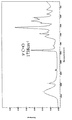
図2には、バインダーとして付着させる熱可塑性樹脂であるポリビニルアルコールのATRスペクトルを示した。このポリビニルアルコールはケン化度が低くC=O伸縮振動に起因するピークが1738cm-1に特徴的に現れる。 FIG. 2 shows an ATR spectrum of polyvinyl alcohol, which is a thermoplastic resin attached as a binder. This polyvinyl alcohol has a low saponification degree, and a peak due to C═O stretching vibration appears characteristically at 1738 cm −1 .
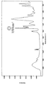
図3には、熱硬化性樹脂であるレゾール型フェノール樹脂とノボラック型フェノール樹脂の混合樹脂のATRスペクトルを示した。これには、フェノール樹脂のC=C環振動に起因するピークが1510cm-1に現れる。 FIG. 3 shows an ATR spectrum of a mixed resin of a resol type phenol resin and a novolac type phenol resin which is a thermosetting resin. In this, a peak due to the C═C ring vibration of the phenol resin appears at 1510 cm −1 .
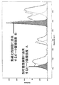
図4には、実施例1の炭素繊維シートの一方の面のATRスペクトルとこのATRスペクトルをピーク分割したものを示した。ピーク面積強度比はATRスペクトルの熱可塑性樹脂であるポリビニルアルコールに由来する1738cm-1のピーク面積Aと、熱硬化性樹脂であるフェノール樹脂に由来する1510cm-1のピーク面積Bとの比Cを以下の式より求めた。
C=B/A
次に、他方の面のATRスペクトルからポリビニルアルコールに由来する1738cm-1のピーク面積Dと、フェノール樹脂に由来する1510cm-1のピーク面積Eとの比Fを以下の式より求めた。
F=E/D
FIG. 4 shows the ATR spectrum of one side of the carbon fiber sheet of Example 1 and the peak-divided ATR spectrum. The peak area intensity ratio is a ratio C between a peak area A of 1738 cm −1 derived from polyvinyl alcohol which is a thermoplastic resin of the ATR spectrum and a peak area B of 1510 cm −1 derived from a phenol resin which is a thermosetting resin. It calculated | required from the following formula | equation.
C = B / A
Next, the ratio F between the peak area D of 1738 cm −1 derived from polyvinyl alcohol and the peak area E of 1510 cm −1 derived from phenol resin was determined from the following formula from the ATR spectrum of the other surface.
F = E / D
<そりの測定>
炭素化した多孔質炭素板から無作為で20cm角を100枚切り出し、1枚毎に平板上に無荷重下で置いたときに平板から最も浮き上がっている点の平板上からの高さH(mm)を測定し、厚さ方向に0.15MPaの一様な面圧をかけたときの多孔質炭素板の厚さT(mm)より、次の式を満たすものが100枚の内95枚以上である場合をそりが無いとする。なお、多孔質炭素板を平板上に乗せたときに一方の面を上にした場合と他方の面を上にした場合で高さHが異なる場合はHの値が大きい方を用いる。
H−T<4(mm)
<Measurement of sled>
Randomly cut 100 pieces of 20 cm square from a carbonized porous carbon plate, and place each plate on a flat plate under no load. Height H (mm) ) And the thickness T (mm) of the porous carbon plate when a uniform surface pressure of 0.15 MPa is applied in the thickness direction, 95 or more out of 100 sheets satisfy the following formula: If there is no warp. When the height H is different between when the porous carbon plate is placed on a flat plate and one surface is up, and when the other surface is up, the higher H value is used.
HT <4 (mm)
実施例2
熱硬化性樹脂溶液の含浸、乾燥工程において、炭素繊維100重量部に対して熱硬化性樹脂のみを150重量部付着させ、また、プレス工程で積層枚数を1枚とした以外は実施例1と同様にして炭素繊維シート、多孔質炭素板を得た。
Example 2
In the impregnation and drying process of the thermosetting resin solution, 150 parts by weight of the thermosetting resin alone was attached to 100 parts by weight of the carbon fibers, and the number of laminated sheets was 1 in the pressing process. Similarly, a carbon fiber sheet and a porous carbon plate were obtained.
実施例3
プレス工程で積層枚数を2枚とし、最高温度2000℃の窒素ガス雰囲気に保たれたバッチ式の炉で、成形した炭素繊維シートを400枚積層し、複数枚の炭素板で成形した炭素繊維シートを挟み込んだ状態で約1.4℃/分の昇温速度で加熱して樹脂を炭化させた以外は実施例2と同様にして炭素繊維シート、多孔質炭素板を得た。
Example 3
A carbon fiber sheet in which 400 sheets of carbon fiber sheets are laminated in a batch furnace maintained in a nitrogen gas atmosphere with a maximum temperature of 2000 ° C., and formed with a plurality of carbon plates. A carbon fiber sheet and a porous carbon plate were obtained in the same manner as in Example 2 except that the resin was carbonized by heating at a rate of temperature increase of about 1.4 ° C./min in a state of sandwiching.
比較例1
炭素繊維紙をフェノール樹脂溶液に含浸、乾燥する際に抄紙表面を上にする以外は実施例2と同様にして炭素繊維シート、多孔質炭素板を得た。
Comparative Example 1
A carbon fiber sheet and a porous carbon plate were obtained in the same manner as in Example 2 except that the surface of the paper was turned up when the carbon fiber paper was impregnated with a phenol resin solution and dried.
比較例2
フェノール樹脂溶液のフェノール樹脂濃度を50重量%とした以外は比較例1と同様にして炭素繊維シート、多孔質炭素板を得た。
Comparative Example 2
A carbon fiber sheet and a porous carbon plate were obtained in the same manner as in Comparative Example 1 except that the concentration of the phenol resin in the phenol resin solution was 50% by weight.
比較例3
炭素繊維紙をフェノール樹脂溶液に含浸、乾燥する際に抄紙表面を上にする以外は実施例3と同様にして炭素繊維シート、多孔質炭素板を得た。以上、実施例1〜3および比較例1〜3の結果を表1に示す。
Comparative Example 3
A carbon fiber sheet and a porous carbon plate were obtained in the same manner as in Example 3 except that the surface of the paper was made upward when the carbon fiber paper was impregnated with a phenol resin solution and dried. The results of Examples 1 to 3 and Comparative Examples 1 to 3 are shown in Table 1 above.

表1からも明らかなように、本発明の目的とするそりの無い多孔質炭素板を得るには、熱硬化性樹脂含浸、乾燥工程後の炭素繊維シートにおける一方の面の熱可塑性樹脂と熱硬化性樹脂のピーク強度比Cと他方の面のピーク強度比Fの比F/Cが以下の式を満たすことが必要であることが分かった。
0.7<F/C(ただしC>Fとする)
これに対し、比較例1、2、3では上の式を満たしておらず、炭化工程が連続式、バッチ式に関わらずそりが発生している。
As is clear from Table 1, in order to obtain the warp-free porous carbon plate of the present invention, the thermoplastic resin and heat on one side of the carbon fiber sheet after the thermosetting resin impregnation and drying steps are used. It was found that the ratio F / C between the peak intensity ratio C of the curable resin and the peak intensity ratio F on the other surface must satisfy the following formula.
0.7 <F / C (where C> F)
In contrast, Comparative Examples 1, 2, and 3 do not satisfy the above formula, and warpage occurs regardless of whether the carbonization process is continuous or batch.
本発明における炭素繊維シートを加熱して熱硬化性樹脂を炭素化してなる多孔質炭素板は、とくに燃料電池のガス拡散体として好適であるが、これに限らず、各種電池の電極基材や脱水機用電極などにも応用することができ、さらに、その応用範囲はこれらに限られるものではない。 Porous carbon plate with a thermosetting resin by heating the definitive carbon fiber sheet of the present invention obtained by carbonization, in particular is suitable as a gas diffuser of the fuel cell is not limited thereto, the electrode base material of various batteries It can also be applied to electrodes for dehydrators and the like, and the application range is not limited to these.
1 抄紙工程
2 樹脂含浸、乾燥工程
3 炭化工程
4 抄紙表面
5 抄紙裏面
6 プレス工程
1 Papermaking process 2 Resin impregnation and
Claims (4)
(2)前記炭素繊維紙に熱硬化性樹脂溶液を含浸させ、加熱して乾燥させ炭素繊維シートを得る工程、
(3)前記炭素繊維シートを加熱し熱硬化性樹脂を炭化させて多孔質炭素板を得る工程、を含む多孔質炭素板の製造方法であって、前記(2)の工程において前記(1)の工程の抄紙時の裏面が上になるように乾燥を行う、多孔質炭素板の製造方法。 (1) A process of obtaining carbon fiber paper by paper-making short carbon fibers and binding the short carbon fibers with a thermoplastic resin;
(2) impregnating the carbon fiber paper with a thermosetting resin solution, heating and drying to obtain a carbon fiber sheet;
(3) A method for producing a porous carbon plate, comprising a step of heating the carbon fiber sheet to carbonize a thermosetting resin to obtain a porous carbon plate, wherein in the step (2), (1) A method for producing a porous carbon plate, wherein drying is carried out so that the back surface at the time of papermaking in the step is on top.
Priority Applications (1)
| Application Number | Priority Date | Filing Date | Title |
|---|---|---|---|
| JP2005067711A JP4591128B2 (en) | 2004-03-17 | 2005-03-10 | Method for producing porous carbon plate |
Applications Claiming Priority (2)
| Application Number | Priority Date | Filing Date | Title |
|---|---|---|---|
| JP2004076483 | 2004-03-17 | ||
| JP2005067711A JP4591128B2 (en) | 2004-03-17 | 2005-03-10 | Method for producing porous carbon plate |
Publications (3)
| Publication Number | Publication Date |
|---|---|
| JP2005297547A JP2005297547A (en) | 2005-10-27 |
| JP2005297547A5 JP2005297547A5 (en) | 2007-12-06 |
| JP4591128B2 true JP4591128B2 (en) | 2010-12-01 |
Family
ID=35329664
Family Applications (1)
| Application Number | Title | Priority Date | Filing Date |
|---|---|---|---|
| JP2005067711A Expired - Lifetime JP4591128B2 (en) | 2004-03-17 | 2005-03-10 | Method for producing porous carbon plate |
Country Status (1)
| Country | Link |
|---|---|
| JP (1) | JP4591128B2 (en) |
Cited By (1)
| Publication number | Priority date | Publication date | Assignee | Title |
|---|---|---|---|---|
| JP2014207240A (en) * | 2012-03-30 | 2014-10-30 | 三菱レイヨン株式会社 | Porous electrode base material |
Families Citing this family (12)
| Publication number | Priority date | Publication date | Assignee | Title |
|---|---|---|---|---|
| JP5106808B2 (en) * | 2006-07-31 | 2012-12-26 | 三菱レイヨン株式会社 | Porous carbon electrode substrate and polymer electrolyte fuel cell using the same |
| JP5311538B2 (en) * | 2008-02-18 | 2013-10-09 | 三菱レイヨン株式会社 | Method for producing porous carbon electrode substrate |
| JP5297701B2 (en) * | 2008-06-20 | 2013-09-25 | 三菱レイヨン株式会社 | Method for producing electrode substrate for polymer electrolyte fuel cell |
| KR100997418B1 (en) | 2008-12-31 | 2010-11-30 | 주식회사 효성 | Method for producing gas diffusion layer for fuel cell having carbon nanotube and carbon composite |
| GB0902312D0 (en) * | 2009-02-12 | 2009-04-01 | Johnson Matthey Plc | Gas diffusion substrate |
| AU2010331411B2 (en) | 2009-12-17 | 2015-06-18 | Toray Industries, Inc. | Layered carbon-fiber product, preform, and processes for producing these |
| JP5709059B2 (en) | 2010-03-19 | 2015-04-30 | 東レ株式会社 | Cutting method of carbon fiber substrate |
| JP6665403B2 (en) * | 2015-01-13 | 2020-03-13 | 住友ベークライト株式会社 | Resin sheet and method for manufacturing resin sheet |
| JP6701674B2 (en) * | 2015-10-30 | 2020-05-27 | 住友ベークライト株式会社 | Method for producing fiber-reinforced plastic molded product |
| JP6825442B2 (en) * | 2017-03-24 | 2021-02-03 | 三菱ケミカル株式会社 | A method of impregnating a porous sheet containing carbon fibers with a liquid substance in which a conductive solid substance is dispersed. |
| JP7767881B2 (en) * | 2021-03-29 | 2025-11-12 | 東レ株式会社 | Prepreg manufacturing method and gas diffusion electrode substrate |
| CN116732814B (en) * | 2023-06-30 | 2024-09-20 | 浙江科技学院 | A method for preparing multi-layer gradient pore carbon paper |
Family Cites Families (7)
| Publication number | Priority date | Publication date | Assignee | Title |
|---|---|---|---|---|
| JPS62270331A (en) * | 1986-05-19 | 1987-11-24 | 日東紡績株式会社 | Carbon fiber sheet-shaped article |
| JPH0818882B2 (en) * | 1987-12-16 | 1996-02-28 | 東レ株式会社 | Method for manufacturing conductive substrate |
| JP4051714B2 (en) * | 1995-12-06 | 2008-02-27 | 東レ株式会社 | Electrode substrate for polymer electrolyte fuel cell and method for producing the same |
| WO2001056103A1 (en) * | 2000-01-27 | 2001-08-02 | Mitsubishi Rayon Co., Ltd. | Porous carbon electrode material, method for manufacturing the same, and carbon fiber paper |
| JP3608053B2 (en) * | 2001-01-16 | 2005-01-05 | 昭和電工株式会社 | Battery catalyst composition, gas diffusion layer, and fuel cell including these |
| JP3712959B2 (en) * | 2001-07-03 | 2005-11-02 | 松下電器産業株式会社 | Fuel cell electrode and method of manufacturing the same |
| JP2003183994A (en) * | 2001-10-09 | 2003-07-03 | Mitsubishi Rayon Co Ltd | Carbon fiber paper and porous carbon electrode substrate for fuel cell using the same |
-
2005
- 2005-03-10 JP JP2005067711A patent/JP4591128B2/en not_active Expired - Lifetime
Cited By (4)
| Publication number | Priority date | Publication date | Assignee | Title |
|---|---|---|---|---|
| JP2014207240A (en) * | 2012-03-30 | 2014-10-30 | 三菱レイヨン株式会社 | Porous electrode base material |
| EP2833450A1 (en) | 2012-03-30 | 2015-02-04 | Mitsubishi Rayon Co., Ltd. | Porous electrode base material, method for manufacturing same and precursor sheet |
| EP2833450A4 (en) * | 2012-03-30 | 2015-04-01 | Mitsubishi Rayon Co | POROUS ELECTRODE BASE MATERIAL, MANUFACTURING METHOD THEREFOR, AND PRECURSOR SHEET |
| US9716278B2 (en) | 2012-03-30 | 2017-07-25 | Mitsubishi Chemical Corporation | Porous electrode base material, method for manufacturing same, and precursor sheet |
Also Published As
| Publication number | Publication date |
|---|---|
| JP2005297547A (en) | 2005-10-27 |
Similar Documents
| Publication | Publication Date | Title |
|---|---|---|
| CA2424948C (en) | Carbon fiber electrode substrate for electrochemical cells | |
| CN100480451C (en) | Porous carbon base material, and preparation method and application thereof | |
| JP4591128B2 (en) | Method for producing porous carbon plate | |
| CN107078310B (en) | Carbon sheets, gas diffusion electrode substrates and fuel cells | |
| JP5702218B2 (en) | Porous electrode substrate for polymer electrolyte fuel cell | |
| CN107302097B (en) | Multi-layer carbon substrate for gas diffusion layer | |
| JP7129751B2 (en) | carbon sheet, gas diffusion electrode substrate, and fuel cell | |
| KR101324703B1 (en) | Method for preparing carbon substrate comprising activated carbon fiber, carbon substrate prepared thereby | |
| JP6855843B2 (en) | Electrodes for redox flow batteries and their manufacturing methods, and redox flow batteries | |
| JP5544960B2 (en) | Porous carbon sheet for polymer electrolyte fuel cell and method for producing the same | |
| JP5055682B2 (en) | Porous carbon plate and method for producing the same | |
| JP7831204B2 (en) | Substrate for gas diffusion layer in fuel cells and method for manufacturing the same | |
| CA3202659A1 (en) | Gas diffusion system with high purity | |
| JP2005297547A5 (en) | ||
| CN115315835B (en) | Method for manufacturing gas diffusion electrode substrate | |
| JP2023549666A (en) | electrode material | |
| TW202545054A (en) | a proton exchange membrane fuel cell with improved contact properties between the gas diffusion layers and the polymer electrolyte membrane | |
| JP2009234851A (en) | Porous carbon sheet and its manufacturing process | |
| JP4730888B2 (en) | Porous electrode substrate and method for producing the same | |
| KR102802336B1 (en) | Carbon fiber carbon sheet and manufacturing method thereof | |
| JP5790186B2 (en) | Method for producing gas diffusion electrode substrate | |
| JP2024122102A (en) | Porous carbon plate and method for producing same | |
| CN117063315A (en) | Electrode substrate and manufacturing method thereof | |
| JP4947352B2 (en) | Method for producing porous carbon material | |
| JP2009076347A (en) | Gas diffusion electrode substrate and its manufacturing method |
Legal Events
| Date | Code | Title | Description |
|---|---|---|---|
| A521 | Request for written amendment filed |
Free format text: JAPANESE INTERMEDIATE CODE: A523 Effective date: 20071023 |
|
| A621 | Written request for application examination |
Free format text: JAPANESE INTERMEDIATE CODE: A621 Effective date: 20071023 |
|
| A977 | Report on retrieval |
Free format text: JAPANESE INTERMEDIATE CODE: A971007 Effective date: 20100513 |
|
| A131 | Notification of reasons for refusal |
Free format text: JAPANESE INTERMEDIATE CODE: A131 Effective date: 20100518 |
|
| A521 | Request for written amendment filed |
Free format text: JAPANESE INTERMEDIATE CODE: A523 Effective date: 20100715 |
|
| TRDD | Decision of grant or rejection written | ||
| A01 | Written decision to grant a patent or to grant a registration (utility model) |
Free format text: JAPANESE INTERMEDIATE CODE: A01 Effective date: 20100817 |
|
| A01 | Written decision to grant a patent or to grant a registration (utility model) |
Free format text: JAPANESE INTERMEDIATE CODE: A01 |
|
| A61 | First payment of annual fees (during grant procedure) |
Free format text: JAPANESE INTERMEDIATE CODE: A61 Effective date: 20100830 |
|
| FPAY | Renewal fee payment (event date is renewal date of database) |
Free format text: PAYMENT UNTIL: 20130924 Year of fee payment: 3 |
|
| R151 | Written notification of patent or utility model registration |
Ref document number: 4591128 Country of ref document: JP Free format text: JAPANESE INTERMEDIATE CODE: R151 |
|
| FPAY | Renewal fee payment (event date is renewal date of database) |
Free format text: PAYMENT UNTIL: 20130924 Year of fee payment: 3 |
|
| EXPY | Cancellation because of completion of term |