JP4583881B2 - Joining method - Google Patents
Joining method Download PDFInfo
- Publication number
- JP4583881B2 JP4583881B2 JP2004318138A JP2004318138A JP4583881B2 JP 4583881 B2 JP4583881 B2 JP 4583881B2 JP 2004318138 A JP2004318138 A JP 2004318138A JP 2004318138 A JP2004318138 A JP 2004318138A JP 4583881 B2 JP4583881 B2 JP 4583881B2
- Authority
- JP
- Japan
- Prior art keywords
- blood vessel
- artificial blood
- intermediate layer
- hole
- artificial
- Prior art date
- Legal status (The legal status is an assumption and is not a legal conclusion. Google has not performed a legal analysis and makes no representation as to the accuracy of the status listed.)
- Active
Links
Images


Description
本発明は、接合方法に関するものである。 The present invention relates to a joining method .
生体血管の一部を人工血管で置換する手術、すなわち、人工血管の移植手術が行われている。 An operation for replacing a part of a biological blood vessel with an artificial blood vessel, that is, an artificial blood vessel transplantation operation is performed.
このような手術で用いられる人工血管には、主管と、当該主管の側部にその端部が接合(端−側接合)された分岐管とを有するものがある。 Some artificial blood vessels used in such operations have a main tube and a branch tube whose end is bonded to the side of the main tube (end-side bonding).
この人工血管における主管と分岐管との接合は、縫合により行われているが、縫合によって接合部の隙間を完全に塞ぐことは事実上不可能であり、手術中、この部位から血液が漏出し、フィブリングルー等の止血剤の使用を余儀なくされることも少なくなかった。 The joint between the main tube and the branch tube in this artificial blood vessel is done by suturing, but it is virtually impossible to completely close the joint gap by suturing, and blood leaks from this site during the operation. In many cases, the use of hemostatic agents such as fibrin glue is forced.
上記接合部の隙間を塞ぐため、液状のプレポリマーをコーティングして重合させる、あるいはポリマーを溶媒に溶解して塗布するといった方法が提案されているが(例えば、特許文献1参照)、操作が煩雑であることに加え、未反応物質あるいは溶媒の残留による毒性の懸念があった。 In order to close the gap between the joints, a method has been proposed in which a liquid prepolymer is coated and polymerized, or the polymer is dissolved in a solvent and applied (for example, see Patent Document 1), but the operation is complicated. In addition to this, there was concern about toxicity due to unreacted substances or residual solvent.
また、上記特許文献1においても、主管と分岐管との接合は、縫合が前提となっており、これまでに縫合以外の接合方法が実用化された例はなかった。 Also in Patent Document 1, the joining of the main tube and the branch tube is based on the premise of stitching, and there has been no example in which a joining method other than suturing has been put to practical use.
本発明の目的は、第1の人工血管と第2の人工血管とを簡単かつ確実に接合することができる接合方法を提供することにある。 The objective of this invention is providing the joining method which can join the 1st artificial blood vessel and the 2nd artificial blood vessel simply and reliably .
このような目的は、下記(1)および(2)の本発明により達成される。 These objects, Ru is achieved by the following aspects of the invention (1) and (2).
(1) 内層、外層およびそれらの間に位置する中間層で構成された管壁を有する第1の人工血管の側部に第2の人工血管の端部を接合する接合方法であって、
前記第1の人工血管の側部に管壁を貫通する孔を形成するとともに、該孔の周囲の外層の一部を欠損させることにより前記中間層が露出する中間層露出部を形成する孔および中間層露出部形成工程と、
前記中間層露出部に、シール部材を介して前記第2の人工血管の端部を融着する第2の人工血管融着工程とを有することを特徴とする接合方法。
( 1 ) A joining method for joining an end portion of a second artificial blood vessel to a side portion of a first artificial blood vessel having a tube wall composed of an inner layer, an outer layer, and an intermediate layer positioned therebetween,
Forming a hole penetrating the tube wall in a side portion of the first artificial blood vessel and forming an intermediate layer exposed portion in which the intermediate layer is exposed by deleting a part of the outer layer around the hole; and Intermediate layer exposed portion forming step;
A joining method comprising: a second artificial blood vessel fusion step of fusing an end portion of the second artificial blood vessel to the intermediate layer exposed portion via a seal member.
(2) 前記第2の人工血管融着工程の後に、前記孔の周囲の部分と、前記第2の人工血管の端部における接合部とを縫合する縫合工程を有する上記(1)に記載の接合方法。 ( 2 ) The method according to ( 1 ), further including a suturing step of suturing a portion around the hole and a joint portion at an end portion of the second artificial blood vessel after the second artificial blood vessel fusion step. Joining method.
本発明によれば、第1の人工血管の孔の周囲の部分と、第2の人工血管の端部との間にシール材(シール部材)を介在させることにより、第1の人工血管と第2の人工血管とを簡単かつ確実に接合することができ、よって、これら人工血管同士の接合箇所から血液が漏れるのを確実に防止することができる。 According to the present invention, the first artificial blood vessel and the first artificial blood vessel can be obtained by interposing a sealing material (seal member) between the peripheral portion of the hole of the first artificial blood vessel and the end portion of the second artificial blood vessel. It is possible to easily and reliably join the two artificial blood vessels, and thus it is possible to reliably prevent blood from leaking from the joint portion between these artificial blood vessels.
また、第1の人工血管の管壁が内層、外層およびそれらの間に位置する中間層で構成されている場合には、当該中間層とシール材とを同種の材料で構成することにより、第1の人工血管と第2の人工血管とをより簡単かつ確実に接合することができる。 Further, when the tube wall of the first artificial blood vessel is composed of the inner layer, the outer layer, and the intermediate layer located between them, the intermediate layer and the sealing material are made of the same kind of material, The one artificial blood vessel and the second artificial blood vessel can be joined more easily and reliably.
以下、本発明の接合方法を添付図面に示す好適な実施形態に基づいて詳細に説明する。 Hereinafter, the joining method of the present invention will be described in detail based on preferred embodiments shown in the accompanying drawings.
<第1実施形態>
図1は、人工血管接合体の第1実施形態を示す斜視図、図2は、図1に示す人工血管接合体における第1の人工血管と第2の人工血管との接合箇所の詳細縦断面図、図3〜図6は、それぞれ、第1の人工血管と第2の人工血管との接合方法を順を追って説明するための図である。なお、以下では、説明の都合上、図1〜図6中の上側を「上」、下側を「下」と言う。
<First Embodiment>
Figure 1 is a perspective view showing a first embodiment of the artificial blood vessel assembly, Figure 2 is a detail longitudinal section of the joint between the first artificial blood vessel and the second artificial blood vessels in the artificial blood vessel assembly shown in Figure 1 FIG. 3 and FIG. 3 to FIG. 6 are diagrams for explaining the joining method of the first artificial blood vessel and the second artificial blood vessel in order. In the following, for convenience of explanation, the upper side in FIGS. 1 to 6 is referred to as “upper” and the lower side is referred to as “lower”.
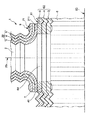
図1に示すように、人工血管接合体1は、第1の人工血管(主管)6と、第1の人工血管6の側部61から分岐する第2の人工血管(分岐管)2とを有している。
As shown in FIG. 1, an artificial blood vessel assembly 1 includes a first artificial blood vessel (main tube) 6 and a second artificial blood vessel (branch tube) 2 branched from a
第1の人工血管6および第2の人工血管2は、それぞれ、全体形状が円筒状をなしているものである。
Each of the first
第1の人工血管6の管壁62および第2の人工血管2の管壁22は、それぞれ、蛇腹状をなしている。これにより、第1の人工血管6および第2の人工血管2をそれぞれ、容易に湾曲させる(曲げる)ことができる。また、第1の人工血管6および第2の人工血管2をそれぞれの中心軸方向(長手方向)に容易に伸長または収縮させることができる。
The
また、図2に示すように、第1の人工血管6の管壁62(側部61)には、当該管壁62を貫通する円形の孔64が形成されている。
As shown in FIG. 2, a
なお、孔64の大きさは、例えば、第2の人工血管2の平均内径とほぼ同等または若干大きいのが好ましい。これにより、血流の乱れが生じて、第1の人工血管6と第2の人工血管2との境界部に、血栓形成が生じることを防止し、より理想的な血流を確保することができる。
Note that the size of the
図1に示すように、第1の人工血管6の平均内径は、第2の人工血管2の平均内径より大きく設定されている。このようにそれぞれの内径(太さ)が異なることにより、所定の生体血管(例えば、大動脈弓とそれから分岐する腕頭動脈)と好適に置換し得る大きさの人工血管接合体1を構成することができる。
As shown in FIG. 1, the average inner diameter of the first
なお、第1の人工血管6の平均内径は、特に限定されず、例えば、8〜40mmであるのが好ましく、20〜30mmであるのがより好ましい。また、第2の人工血管2の平均内径は、特に限定されず、例えば、6〜14mmであるのが好ましく、8〜12mmであるのがより好ましい。
In addition, the average internal diameter of the 1st
また、第1の人工血管6の長さは、特に限定されず、例えば、15〜100cmであるのが好ましく、30〜60cmであるのがより好ましい。
Moreover, the length of the 1st
また、第2の人工血管2の長さは、特に限定されず、例えば、5〜40cmであるのが好ましく、15〜30cmであるのがより好ましい。 Moreover, the length of the 2nd artificial blood vessel 2 is not specifically limited, For example, it is preferable that it is 5-40 cm, and it is more preferable that it is 15-30 cm.
このような人工血管接合体1では、第2の人工血管の下端部(端部)21が第1の人工血管6の側部61に接合されており、第2の人工血管の中心軸23と第1の人工血管6の中心軸63とがほぼ直交している(図2参照)。第1の人工血管6の管壁62の構成と第2の人工血管の管壁22の構成とは、ほぼ同一であるため、以下、第1の人工血管6について代表的に説明する。
In such an artificial blood vessel joined body 1, the lower end portion (end portion) 21 of the second artificial blood vessel is joined to the
図2に示すように、第1の人工血管6の管壁62は、内層3、外層5およびそれらの間に位置する中間層4で構成されている。
As shown in FIG. 2, the
内層3の構成材料としては、特に限定されず、例えば、ポリエチレンテレフタレート(PET)、ポリブチレンテレフタレート(PBT)、ポリテトラフルオロエチレン(PTFE)、エステル系やエーテル系のポリウレタン、ポリエステル−ポリエーテルブロック共重合体、ポリエステル−ポリエステルブロック重合体のようなポリエステル系樹脂等を用いることができる。
The constituent material of the
なお、内層3の厚さは、特に限定されず、例えば、50〜500μm程度とすることができる。
In addition, the thickness of the
中間層4の構成材料としては、特に限定されず、例えば、スチレン系、ポリオレフィン系、ポリ塩化ビニル系、ポリウレタン系、ポリエステル系、ポリアミド系、ポリブタジエン系、トランスポリイソプレン系、フッ素ゴム系、塩素化ポリエチレン系等の各種熱可塑性エラストマーが挙げられ、これらの内の少なくとも1種を主材料とするものを用いることができる。
The constituent material of the
これらの中でも、中間層4の構成材料としては、特に、主鎖に不飽和結合が存在しない熱可塑性エラストマーが好ましい。これにより、生体内に人工血管接合体1を留置した際に、中間層4が酸化により劣化するのを防止することができる。このような熱可塑性エラストマーとしては、例えば、スチレン系のものとして、スチレン−エチレン−ブチレン−スチレンブロック共重合体(SEBS)、スチレン−エチレン−プロピレン−スチレンブロック共重合体(SEPS)、スチレン−エチレン−エチレン−プロピレン−スチレンブロック共重合体(SEEPS)等が挙げられる。
Among these, as the constituent material of the
なお、中間層4の厚さは、特に限定されず、例えば、100〜500μm程度とすることができる。
In addition, the thickness of the intermediate |
外層5の構成材料としては、特に限定されず、例えば、前述した内層3の構成材料と同様のものを用いることができる。
The constituent material of the
なお、外層5の厚さは、特に限定されず、例えば、50〜500μm程度とすることができる。
In addition, the thickness of the
このような構成の人工血管接合体1では、第1の人工血管6における露出した中間層4(中間層露出部41)と、第2の人工血管2の下端部21とが、シール材(シール部)7を介して熱融着されている(図2参照)。なお、中間層露出部41は、孔64の周囲の外層5の一部を欠損させることにより露出させることができる。
In the artificial blood vessel assembly 1 having such a configuration, the exposed intermediate layer 4 (intermediate layer exposed portion 41) in the first
また、図2に示すように、下端部21は、その全周にわたり外方に向けて突出するフランジ部で構成されている。これにより、シール材7との接合面積が大きくなり、第2の人工血管2がより確実に接合される。
Moreover, as shown in FIG. 2, the
また、シール材7は、後述するシート状のシール部材71を、第1の人工血管6(中間層4)と第2の人工血管2(下端部21)との間で溶融固化されたものである。
The sealing
図4(d)に示すように、シール材7は、その形状が孔64を囲むようなリング状(円環状)をなしている。すなわち、シール材7は、その形状が第2の人工血管2の開口部(下端部21)とほぼ同様の形状をなしている。これにより、第1の人工血管6と第2の人工血管2とを接合(熱融着)するとき、シール材7に対する第2の人工血管2の位置合わせを容易にすることができ、よって、第1の人工血管6と第2の人工血管2とが確実に接合され得る。
As shown in FIG. 4D, the
なお、シール材7(シール部材71)の構成材料は、中間層4と同種の構成材料とするのが好ましい。これにより、シール材7および中間層4(中間層露出部41)を加熱することで、シール材7と中間層4とを容易(簡単)かつ確実に接合(熱融着)することができ、よって、第1の人工血管6と第2の人工血管2とをより容易(簡単)かつ確実に接合することができる。
The constituent material of the sealing material 7 (seal member 71) is preferably the same type of constituent material as that of the
また、シール材7の厚さは、特に限定されず、例えば、50〜500μmであるのが好ましく、100〜300μmであるのがより好ましい。
Moreover, the thickness of the sealing
また、シール材7の外径は、特に限定されず、第2の人工血管2の平均外径とほぼ同等またはそれより若干大きいのが好ましい。
Further, the outer diameter of the sealing
図2に示すように、第1の人工血管6の孔64の周囲の部分(縁部)と、第2の人工血管2の下端部21における接合部211とが、縫合糸8により、縫合されているのが好ましい。これにより、第1の人工血管6と第2の人工血管2とをより確実に接合することができる。
As shown in FIG. 2, the portion (edge) around the
なお、孔64の周囲の部分と接合部211とは、それらの全周に渡って縫合されているのが好ましい。
In addition, it is preferable that the peripheral part of the
次に、第1の人工血管6の側部61に第2の人工血管2の下端部21を接合する接合方法について説明する。
Next, a joining method for joining the
[1] 孔および中間層露出部形成工程(孔形成工程)
まず、第1の人工血管6の側部61における、第2の人工血管2を接合(融着)する接合位置を決める。
[1] Hole and intermediate layer exposed portion forming step (hole forming step)
First, the joining position at which the second artificial blood vessel 2 is joined (fused) on the
次に、図3(a)に示すように、例えばポンチ(図示せず)を用いて、第1の人工血管6の側部61の前記接合位置に、管壁62を貫通する孔64を形成する。なお、孔64の大きさは、前述したように、第2の人工血管2の内径とほぼ同等またはそれより若干大きく設定する。なお、ポンチを用いる場合には、第1の人工血管6内に、例えば打ち抜き敷板(受け部)を挿入するのが好ましい。
Next, as shown in FIG. 3A, a
また、前記孔64の形成に伴って、当該孔64の周囲の外層5をリング状に除去する(欠損させる)。これにより、リング状の中間層露出部41を形成することができる。
Further, as the
[2] 第2の人工血管融着工程
[2−1] シール部材融着工程
図3(b)、図4(c)に示すように、中間層露出部41の大きさより大きいシール部材71を、孔64を覆うように中間層露出部41に載置する。
[2] Second Artificial Vascular Fusion Process [2-1] Seal Member Fusion Process As shown in FIGS. 3B and 4C, a
その後、例えばヒータ(図示せず)を用いて、中間層露出部41の形状に沿って、すなわち、リング状にシール部材71を加熱して融着する。
Thereafter, the
次に、中間層露出部41(側部61)に融着されたシール部材71の外周部(縁部)を除去するとともに、孔64に対応する孔72をシール部材71に設ける。これにより、リング状をなすシール部材71(シール材7)が形成される(図4(d)参照)。
Next, the outer peripheral portion (edge) of the
[2−2] 第2の人工血管作製工程
接合する第2の人工血管2の長さを決定する。第2の人工血管2の長さを例えば20cmとする場合には、それより長い人工血管を20cmの長さに切断して作製する。
[2-2] Second artificial blood vessel preparation step The length of the second artificial blood vessel 2 to be joined is determined. When the length of the second artificial blood vessel 2 is 20 cm, for example, a longer artificial blood vessel is cut into a length of 20 cm.
なお、第2の人工血管2における切断箇所は、特に限定されず、例えば、管壁22における蛇腹の谷の底部または山の頂部であるのが好ましい。
In addition, the cutting | disconnection location in the 2nd artificial blood vessel 2 is not specifically limited, For example, it is preferable that it is the bottom part of the bellows valley in the
谷の底部で切断した場合は、図5(e)に示すように、第2の人工血管2の下端部21を外翻させ(広げ)、この外翻された部分を接合部211とすることができる。
When cutting at the bottom of the valley, as shown in FIG. 5 (e), the
山の頂部で切断した場合は、山の斜面の裏側の面、すなわち、切断箇所近傍の内周面をそのまま接合部211とすることができる。
When cutting at the top of the mountain, the surface on the back side of the slope of the mountain, that is, the inner peripheral surface in the vicinity of the cut portion can be used as the joining
なお、谷の底部で切断した場合は、下端部21を外翻させるのに限定されず、例えば、下端部21を外側に折り返してもよい。
In addition, when it cut | disconnects at the bottom part of a trough, it is not limited to turning over the
[2−3] 第2の人工血管融着工程
図5(e)、(f)に示すように、前記[2−1]で第1の人工血管6に融着されたシール部材71を介して、中間層露出部41に、前記[2−2]で製作した第2の人工血管2の下端部21を熱融着する。
[2-3] Second Artificial Vascular Fusion Process As shown in FIGS. 5E and 5F, the
[3] 縫合工程
図6に示すように、孔64の周囲の部分と、第2の人工血管2の接合部211とを、縫合糸8を用いて縫合する。
[3] Suture Step As shown in FIG. 6, the portion around the
以上のような工程を経ることにより、第1の人工血管6と第2の人工血管2とを容易かつ確実に接合することができ、よって、これら人工血管同士の接合箇所から血液が漏れるのを確実に防止することができる。また、このような接合の人工血管接合体1を得ることができる。
By passing through the above steps, the first
なお、前記[1]における外層5をリング状に除去する方法としては、特に限定されず、例えば、孔64の径より大きい径の除去用治具(図示せず)を用いて外層5を除去してもよいし、指先で外層5を剥離して(剥き取って)もよい。
The method for removing the
また、前記[2]では、シール部材71を第1の人工血管6の側部61に融着した後、当該融着されたシール部材71に第2の人工血管2の下端部21を融着したが、これに限定されず、例えば、シール部材71を第2の人工血管2の下端部21に融着した後、当該融着されたシール部材71に第1の人工血管6の側部61を融着してもよい。
In [2], after the sealing
また、前記[2−1]では、中間層露出部41の外形に合った円盤状のシール部材71を融着してもよい。その場合、シール部材71の外周部を除去することが省略され、シール部材71に孔72を設けるのみとすることができる。
In [2-1], a disc-shaped
また、前記[2−1]では、中間層露出部41の形状に合ったリング状のシール部材71を融着してもよい。その場合、シール部材71の外周部を除去することと、孔72を設けることとを省略することができる。
In [2-1], a ring-shaped sealing
また、前記[3]の後に、孔64の周囲の部分と第2の人工血管2の接合部211との接合箇所を再度、加熱してもよい。
また、本発明の接合方法では、前記[3]を省略することができる。
Further, after [3], the joint portion between the portion around the
In the joining method of the present invention, the above [3] can be omitted.
<第2実施形態>
図7は、人工血管接合体の第2実施形態を示す斜視図である。
<Second Embodiment>
FIG. 7 is a perspective view showing a second embodiment of the artificial blood vessel assembly .
以下、この図を参照して人工血管接合体の第2実施形態について説明するが、前述した実施形態との相違点を中心に説明し、同様の事項はその説明を省略する。 Hereinafter, the second embodiment of the artificial blood vessel joined body will be described with reference to this figure, but the description will focus on differences from the above-described embodiment, and the description of the same matters will be omitted.
本実施形態は、第2の人工血管の設置数(形成数)が異なること以外は前記第1実施形態と同様である。 This embodiment is the same as the first embodiment except that the number of second artificial blood vessels (number of formation) is different.
図7に示す人工血管接合体1Aは、第1の人工血管6の側部61に4本の第2の人工血管2a、2b、2cおよび2dが設けられて(接合されて)いる。
In the artificial blood vessel joined
第2の人工血管2a、2bおよび2cは、第1の人工血管6の中心軸方向(長手方向)に沿って等間隔に設けられている。
The second
また、第2の人工血管2dは、第2の人工血管2aに対し、第1の人工血管6の中心軸63回りに(第1の人工血管6の周方向に沿って)ほぼ90度異なる位置(方向)に設けられている。
Further, the second artificial blood vessel 2d differs from the second artificial blood vessel 2a by about 90 degrees around the
このように複数(本実施形態では、4つ)の第2の人工血管が設けられていることにより、所定の生体血管(例えば、大動脈弓とそれから分岐する腕頭動脈および左総頸動脈等)と好適に置換し得る形状(構成)の人工血管接合体1を形成することができる。 By providing a plurality of (four in the present embodiment) second artificial blood vessels in this way, a predetermined biological blood vessel (for example, the aortic arch and the brachiocephalic artery and the left common carotid artery branched therefrom) Thus, the artificial blood vessel assembly 1 having a shape (configuration) that can be suitably replaced can be formed.
なお、第2の人工血管2a、2bおよび2cは、等間隔に設けられているのに限定されず、例えば、各間隔が異なるように設けられていてもよい。
Note that the second
また、第2の人工血管2aと第2の人工血管2dとは、互いに90度異なる方向に設けられているのに限定されず、例えば、30度、45度、60度、120度、150度または180度異なる方向に設けられていてもよい。 Further, the second artificial blood vessel 2a and the second artificial blood vessel 2d are not limited to being provided in directions different from each other by 90 degrees. For example, 30 degrees, 45 degrees, 60 degrees, 120 degrees, and 150 degrees are provided. Alternatively, they may be provided in directions different by 180 degrees.
また、第2の人工血管は、第1の人工血管6の中心軸方向および周方向にそれぞれ、複数設けられているのに限定されず、例えば、第1の人工血管6の中心軸方向のみに複数設けられていてもよいし、第1の人工血管6の周方向のみに複数設けられていてもよい。
In addition, the second artificial blood vessel is not limited to being provided in plural in the central axis direction and the circumferential direction of the first
また、第2の人工血管は、第1の人工血管6の中心軸方向に3本設けられているのに限定されず、例えば、2本または4本以上設けられていてもよい。
Further, the number of the second artificial blood vessels is not limited to three provided in the central axis direction of the first
また、第2の人工血管は、第1の人工血管6の周方向に2本設けられているのに限定されず、例えば、3本以上設けられていてもよい。
Further, the number of the second artificial blood vessels is not limited to two provided in the circumferential direction of the first
<第3実施形態>
図8〜図10は、それぞれ、第1の人工血管と第2の人工血管との接合方法を順を追って説明するための図である。なお、以下では、説明の都合上、図8〜図10中の上側を「上」、下側を「下」と言う。
<Third Embodiment>
FIGS. 8 to 10 are diagrams for sequentially explaining the method of joining the first artificial blood vessel and the second artificial blood vessel. Hereinafter, for convenience of explanation, the upper side in FIGS. 8 to 10 is referred to as “upper” and the lower side is referred to as “lower”.
以下、これらの図を参照して人工血管接合体の第3実施形態について説明するが、前述した実施形態との相違点を中心に説明し、同様の事項はその説明を省略する。 Hereinafter, the third embodiment of the artificial blood vessel assembly will be described with reference to these drawings, but the description will focus on the differences from the above-described embodiment, and the description of the same matters will be omitted.
本実施形態は、第1の人工血管の側部に第2の人工血管の下端部を接合する接合方法が異なること以外は前記第1実施形態と同様である。 This embodiment is the same as the first embodiment except that the joining method for joining the lower end portion of the second artificial blood vessel to the side portion of the first artificial blood vessel is different.
[1] シール部材融着工程
まず、第1の人工血管6の側部61における、第2の人工血管2を接合(融着)する接合位置を決める。
[1] Seal member fusion process First, a joining position for joining (fusing) the second artificial blood vessel 2 in the
次に、図8(a)、(b)に示すように、第1の人工血管6の側部61の前記接合位置に、シール部材71を載置する。
Next, as shown in FIGS. 8A and 8B, a
その後、例えばヒータ(図示せず)を用いて、リング状にシール部材71を加熱して融着する。
Thereafter, the
[2] 孔形成工程
側部61に融着されたシール部材71の外周部(縁部)を除去するとともに、シール部材71の内側に、シール部材71と第1の人工血管6の管壁62(側部61)とを貫通する孔64を設ける。これにより、リング状をなすシール部材71(シール材7)が形成される(図9(c)参照)。
[2] Hole Formation Step The outer peripheral portion (edge) of the
[3] 第2の人工血管融着工程
図9(d)、図10(e)に示すように、前記[2]で第1の人工血管6に融着されたシール部材71を介して、側部61に第2の人工血管2の下端部21を熱融着する。
[3] Second Artificial Vascular Fusion Process As shown in FIGS. 9D and 10E, the
[4] 縫合工程
図10(f)に示すように、孔64の周囲の部分と、第2の人工血管2の接合部211とを、縫合糸8を用いて縫合する。
[4] Suture Step As shown in FIG. 10 (f), the portion around the
以上のような工程を経ることにより、第1の人工血管6と第2の人工血管2とを容易かつ確実に接合することができる。また、このような接合の人工血管接合体1を得ることができる。
By passing through the above processes, the 1st
なお、前記[1]において、シール部材71を載置する前に、第1の人工血管6の側部61の前記接合位置の外層5を除去してもよい。
In [1], the
また、前記[1]では、第2の人工血管2の接合部211(下端部21)の外形に合った円盤状のシール部材71を融着してもよい。その場合、シール部材71の外周部を除去することを省略することができる。
In [1], a disc-shaped
以上、本発明の接合方法を図示の各実施形態について説明したが、本発明は、これらに限定されるものではなく、人工血管接合体を構成する各部は、同様の機能を発揮し得る任意の構成のものと置換することができる。また、任意の構成物が付加されていてもよい。 As mentioned above, although the joining method of this invention was demonstrated about each embodiment shown in figure, this invention is not limited to these, Each part which comprises an artificial blood vessel conjugate | zygote is arbitrary which can exhibit the same function. It can be replaced with that of the configuration. Moreover, arbitrary components may be added.
また、第1の人工血管および第2の人工血管は、双方の管壁が蛇腹状をなしていているのに限定されず、例えば、一方の管壁のみが蛇腹状をなしていてもよい。 Further, the first artificial blood vessel and the second artificial blood vessel are not limited to the fact that both the tube walls have a bellows shape. For example, only one tube wall may have a bellows shape.
また、第2の人工血管の中心軸は、第1の人工血管の中心軸に対してほぼ直交しているのに限定されず、例えば、第1の人工血管の中心軸に対して傾斜していてもよい。この場合、第1の人工血管の側部の孔は、その形状が円形であってもよいが、楕円形であるのが好ましい。 Further, the central axis of the second artificial blood vessel is not limited to being substantially orthogonal to the central axis of the first artificial blood vessel. For example, the second artificial blood vessel is inclined with respect to the central axis of the first artificial blood vessel. May be. In this case, the side hole of the first artificial blood vessel may have a circular shape, but is preferably elliptical.
また、第1の人工血管および第2の人工血管は、双方の管壁が複層構造であるのに限定されず、例えば、一方の管壁のみが複層構造または単層構造であってもよいし、双方の管壁が単層構造であってもよい。 In addition, the first artificial blood vessel and the second artificial blood vessel are not limited to both the tube walls having a multilayer structure. For example, only one of the tube walls may have a multilayer structure or a single layer structure. Alternatively, both tube walls may have a single layer structure.
また、中間層の構成材料としては、前述したような材料を用いることができるが、その中でも、特に、融点(熱変形温度)が、内層や外層の融点または熱分解温度より10℃以上低い材料であるのが好ましく、30℃以上低い材料であるのがより好ましい。これにより、第1の人工血管に第2の人工血管を融着するとき、内層や外層が加熱により劣化するのを防止または抑制(軽減)することができる。 In addition, as the constituent material of the intermediate layer, the materials described above can be used, and among them, in particular, a material whose melting point (thermal deformation temperature) is 10 ° C. or more lower than the melting point or thermal decomposition temperature of the inner layer or the outer layer. It is preferable that the material is lower by 30 ° C. or more. Thereby, when the second artificial blood vessel is fused to the first artificial blood vessel, it is possible to prevent or suppress (reduce) the deterioration of the inner layer and the outer layer due to heating.
また、中間層の構成材料としては、前述したような材料を用いることができるが、これらの材料に、相溶性のある低分子量樹脂、鉱物油またはスクワラン等のオイル分を加えるようにしてもよい。これにより、中間層が熱変形する温度(熱変形温度)を低下させることができる。 Further, as the constituent material of the intermediate layer, the materials as described above can be used, but an oil component such as a compatible low molecular weight resin, mineral oil or squalane may be added to these materials. . Thereby, the temperature (thermal deformation temperature) at which the intermediate layer is thermally deformed can be lowered.
また、第1の人工血管と第2の人工血管とを接合するとき、第2の人工血管の下端部における中間層を、第1の人工血管の孔の周囲における中間層と同様に、露出させてもよい。 Further, when joining the first artificial blood vessel and the second artificial blood vessel, the intermediate layer at the lower end of the second artificial blood vessel is exposed in the same manner as the intermediate layer around the hole of the first artificial blood vessel. May be.
また、第1の人工血管と第2の人工血管とは、熱融着により接合されているのに限定されず、例えば、超音波融着、高周波融着等により接合されていてもよい。 In addition, the first artificial blood vessel and the second artificial blood vessel are not limited to being joined by heat fusion, and may be joined by, for example, ultrasonic fusion, high frequency fusion, or the like.
また、第1の人工血管における孔の形成は、ポンチを用いるのに限定されず、例えば、ハサミ、熱ゴテ、レーザ光、カミソリ(カッター)等を用いてもよい。 Further, the formation of the hole in the first artificial blood vessel is not limited to using a punch, and for example, scissors, a thermal iron, a laser beam, a razor (cutter), or the like may be used.
1、1A 人工血管接合体
2、2a、2b、2c、2d 第2の人工血管
21 下端部
211 接合部
22 管壁
23 中心軸
3 内層
4 中間層
41 中間層露出部
5 外層
6 第1の人工血管
61 側部
62 管壁
63 中心軸
64 孔
7 シール材
71 シール部材
72 孔
8 縫合糸
DESCRIPTION OF
Claims (2)
前記第1の人工血管の側部に管壁を貫通する孔を形成するとともに、該孔の周囲の外層の一部を欠損させることにより前記中間層が露出する中間層露出部を形成する孔および中間層露出部形成工程と、
前記中間層露出部に、シール部材を介して前記第2の人工血管の端部を融着する第2の人工血管融着工程とを有することを特徴とする接合方法。 A joining method for joining an end portion of a second artificial blood vessel to a side portion of a first artificial blood vessel having a tube wall composed of an inner layer, an outer layer, and an intermediate layer positioned therebetween,
Forming a hole penetrating the tube wall in a side portion of the first artificial blood vessel and forming an intermediate layer exposed portion in which the intermediate layer is exposed by deleting a part of the outer layer around the hole; and Intermediate layer exposed portion forming step;
A joining method comprising: a second artificial blood vessel fusion step of fusing an end portion of the second artificial blood vessel to the intermediate layer exposed portion via a seal member.
Priority Applications (1)
| Application Number | Priority Date | Filing Date | Title |
|---|---|---|---|
| JP2004318138A JP4583881B2 (en) | 2004-11-01 | 2004-11-01 | Joining method |
Applications Claiming Priority (1)
| Application Number | Priority Date | Filing Date | Title |
|---|---|---|---|
| JP2004318138A JP4583881B2 (en) | 2004-11-01 | 2004-11-01 | Joining method |
Related Child Applications (1)
| Application Number | Title | Priority Date | Filing Date |
|---|---|---|---|
| JP2010165092A Division JP5054166B2 (en) | 2010-07-22 | 2010-07-22 | Artificial vascular conjugate |
Publications (3)
| Publication Number | Publication Date |
|---|---|
| JP2006122578A JP2006122578A (en) | 2006-05-18 |
| JP2006122578A5 JP2006122578A5 (en) | 2007-10-25 |
| JP4583881B2 true JP4583881B2 (en) | 2010-11-17 |
Family
ID=36717847
Family Applications (1)
| Application Number | Title | Priority Date | Filing Date |
|---|---|---|---|
| JP2004318138A Active JP4583881B2 (en) | 2004-11-01 | 2004-11-01 | Joining method |
Country Status (1)
| Country | Link |
|---|---|
| JP (1) | JP4583881B2 (en) |
Cited By (1)
| Publication number | Priority date | Publication date | Assignee | Title |
|---|---|---|---|---|
| US10709450B2 (en) | 2015-10-13 | 2020-07-14 | Korea Institute Of Machinery & Materials | Blood vessel connecting apparatus |
Families Citing this family (4)
| Publication number | Priority date | Publication date | Assignee | Title |
|---|---|---|---|---|
| DE102005039685B4 (en) * | 2005-08-22 | 2007-10-11 | Siemens Ag | Method for identifying a contrasted blood vessel in digital image data |
| CN101953721B (en) * | 2010-10-28 | 2013-06-05 | 东华大学 | Preparation method of multilayer composite artificial vascular membrane with shape memory function |
| JP5912556B2 (en) * | 2012-01-13 | 2016-04-27 | 有限会社ナイセム | Suture for medical device sewing, its use, and medical device sewn using the suture |
| CN108066044B (en) * | 2016-11-07 | 2023-12-29 | 大连科万维医疗科技有限公司 | Adjustable artificial blood vessel with hemorrhage preventing function |
Citations (5)
| Publication number | Priority date | Publication date | Assignee | Title |
|---|---|---|---|---|
| WO1999012496A1 (en) * | 1997-09-08 | 1999-03-18 | Terumo Kabushiki Kaisha | Blood vessel prosthesis |
| JP2001514043A (en) * | 1997-09-04 | 2001-09-11 | ボストン サイエンティフィック リミテッド | Aortic arch graft |
| JP2003019137A (en) * | 2001-07-09 | 2003-01-21 | Terumo Corp | Blood vessel joining tool |
| JP2003509157A (en) * | 1999-09-22 | 2003-03-11 | インプラ・インコーポレーテッド | Abdominal aortic aneurysm prosthesis |
| WO2003049644A1 (en) * | 2001-12-07 | 2003-06-19 | Boston Scientific Limited | Anatomically curved graft for implantation at the aortic arch |
Family Cites Families (2)
| Publication number | Priority date | Publication date | Assignee | Title |
|---|---|---|---|---|
| JPH0428360A (en) * | 1990-05-24 | 1992-01-30 | Nippon Zeon Co Ltd | Artificial blood vessel and anastomosis for artificial blood vessel |
| JP2842547B2 (en) * | 1993-06-18 | 1999-01-06 | 宇部興産株式会社 | Bifurcated vascular graft |
-
2004
- 2004-11-01 JP JP2004318138A patent/JP4583881B2/en active Active
Patent Citations (5)
| Publication number | Priority date | Publication date | Assignee | Title |
|---|---|---|---|---|
| JP2001514043A (en) * | 1997-09-04 | 2001-09-11 | ボストン サイエンティフィック リミテッド | Aortic arch graft |
| WO1999012496A1 (en) * | 1997-09-08 | 1999-03-18 | Terumo Kabushiki Kaisha | Blood vessel prosthesis |
| JP2003509157A (en) * | 1999-09-22 | 2003-03-11 | インプラ・インコーポレーテッド | Abdominal aortic aneurysm prosthesis |
| JP2003019137A (en) * | 2001-07-09 | 2003-01-21 | Terumo Corp | Blood vessel joining tool |
| WO2003049644A1 (en) * | 2001-12-07 | 2003-06-19 | Boston Scientific Limited | Anatomically curved graft for implantation at the aortic arch |
Cited By (1)
| Publication number | Priority date | Publication date | Assignee | Title |
|---|---|---|---|---|
| US10709450B2 (en) | 2015-10-13 | 2020-07-14 | Korea Institute Of Machinery & Materials | Blood vessel connecting apparatus |
Also Published As
| Publication number | Publication date |
|---|---|
| JP2006122578A (en) | 2006-05-18 |
Similar Documents
| Publication | Publication Date | Title |
|---|---|---|
| US10980633B2 (en) | Prosthetic valved conduits with mechanically coupled leaflets | |
| US5755778A (en) | Anastomosis device | |
| JP2020509888A5 (en) | ||
| US5011555A (en) | Method of ultrasonically cutting and sealing thermoplastic workpieces particularly a filter | |
| EP3253332B1 (en) | Stent seals and method of production | |
| AU2020210253A1 (en) | Prosthetic valves with mechanically coupled leaflets | |
| JP4278630B2 (en) | Laminated self-sealing vascular access graft | |
| US20080103587A1 (en) | Multi-furcated ePTFE grafts and stent-graft prostheses and methods of making the same | |
| US20050149073A1 (en) | Mechanisms and methods used in the anastomosis of biological conduits | |
| JP4583881B2 (en) | Joining method | |
| US20080097592A1 (en) | Artificial Blood Vessel | |
| JP5054166B2 (en) | Artificial vascular conjugate | |
| JP2010063648A (en) | Distal-end flexible medical tube | |
| US20110212294A1 (en) | Breathable structure and method for breathable structure formation | |
| JP2003019137A (en) | Blood vessel joining tool | |
| JP3568756B2 (en) | Vascular prosthesis fitting | |
| WO2020196882A1 (en) | Adhesion-promoting device | |
| JP6840607B2 (en) | Balloon catheter | |
| JP5550195B2 (en) | Drug discharge member and medical multi-chamber container | |
| JPH0399667A (en) | Container for medical care | |
| JP6073042B2 (en) | Resin sheet bonding method | |
| JP7410130B2 (en) | Healing promotion device | |
| JP2003513696A (en) | Apparatus and method for placing multiple sutures during an anastomosis | |
| US20230181277A1 (en) | System for connecting medical draping | |
| JPH0428360A (en) | Artificial blood vessel and anastomosis for artificial blood vessel |
Legal Events
| Date | Code | Title | Description |
|---|---|---|---|
| A521 | Request for written amendment filed |
Free format text: JAPANESE INTERMEDIATE CODE: A523 Effective date: 20070906 |
|
| A621 | Written request for application examination |
Free format text: JAPANESE INTERMEDIATE CODE: A621 Effective date: 20070906 |
|
| A977 | Report on retrieval |
Free format text: JAPANESE INTERMEDIATE CODE: A971007 Effective date: 20100202 |
|
| A131 | Notification of reasons for refusal |
Free format text: JAPANESE INTERMEDIATE CODE: A131 Effective date: 20100525 |
|
| A521 | Request for written amendment filed |
Free format text: JAPANESE INTERMEDIATE CODE: A523 Effective date: 20100722 |
|
| TRDD | Decision of grant or rejection written | ||
| A01 | Written decision to grant a patent or to grant a registration (utility model) |
Free format text: JAPANESE INTERMEDIATE CODE: A01 Effective date: 20100817 |
|
| A01 | Written decision to grant a patent or to grant a registration (utility model) |
Free format text: JAPANESE INTERMEDIATE CODE: A01 |
|
| A61 | First payment of annual fees (during grant procedure) |
Free format text: JAPANESE INTERMEDIATE CODE: A61 Effective date: 20100901 |
|
| R150 | Certificate of patent or registration of utility model |
Ref document number: 4583881 Country of ref document: JP Free format text: JAPANESE INTERMEDIATE CODE: R150 Free format text: JAPANESE INTERMEDIATE CODE: R150 |
|
| FPAY | Renewal fee payment (event date is renewal date of database) |
Free format text: PAYMENT UNTIL: 20130910 Year of fee payment: 3 |
|
| R250 | Receipt of annual fees |
Free format text: JAPANESE INTERMEDIATE CODE: R250 |
|
| R250 | Receipt of annual fees |
Free format text: JAPANESE INTERMEDIATE CODE: R250 |
|
| R250 | Receipt of annual fees |
Free format text: JAPANESE INTERMEDIATE CODE: R250 |
|
| R250 | Receipt of annual fees |
Free format text: JAPANESE INTERMEDIATE CODE: R250 |
|
| R250 | Receipt of annual fees |
Free format text: JAPANESE INTERMEDIATE CODE: R250 |