JP4581175B2 - Air conditioner - Google Patents
Air conditioner Download PDFInfo
- Publication number
- JP4581175B2 JP4581175B2 JP2000086329A JP2000086329A JP4581175B2 JP 4581175 B2 JP4581175 B2 JP 4581175B2 JP 2000086329 A JP2000086329 A JP 2000086329A JP 2000086329 A JP2000086329 A JP 2000086329A JP 4581175 B2 JP4581175 B2 JP 4581175B2
- Authority
- JP
- Japan
- Prior art keywords
- reactor
- air conditioner
- semiconductor switching
- heat
- resin
- Prior art date
- Legal status (The legal status is an assumption and is not a legal conclusion. Google has not performed a legal analysis and makes no representation as to the accuracy of the status listed.)
- Expired - Fee Related
Links
Images


Classifications
-
- H—ELECTRICITY
- H01—ELECTRIC ELEMENTS
- H01L—SEMICONDUCTOR DEVICES NOT COVERED BY CLASS H10
- H01L2924/00—Indexing scheme for arrangements or methods for connecting or disconnecting semiconductor or solid-state bodies as covered by H01L24/00
- H01L2924/0001—Technical content checked by a classifier
- H01L2924/0002—Not covered by any one of groups H01L24/00, H01L24/00 and H01L2224/00
Description
【0001】
【発明の属する技術分野】
この発明は、半導体スイッチング素子により、高調波抑制、力率改善を行なうコンバータ装置を備えた空気調和機に関するものである。
【0002】
【従来の技術】
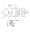
従来の空気調和機におけるコンバータ装置のリアクトル実装方法および冷却方法について、図1、図2を基に説明する。図1は、従来の半導体スイッチング素子により、高調波抑制、力率改善を行なうコンバータ装置を備えた空気調和機の簡易回路図である。図2は、従来の空気調和機におけるコンバータ装置のリアクトル実装状態を図示したもので、空気調和機の室外機を上部から見た断面図である。
【0003】
図1において、1は半導体スイッチング素子、2は高調波抑制、力率改善を行なうためのリアクトル、3はリアクトル2を主回路基板4に電気的に接続するリード線、13は電界コンデンサ、16はダイオード、23はシャント抵抗、24はゲート抵抗である。図2において、5は主回路基板4に取り付けられ、基板上に実装された発熱部品の放熱を促す放熱手段、6は室外ファン、7は室外機、8は室外機7内の室外ファン6上流側に配設された熱交換器、9は主回路基板4やリアクトル2を内包する電機品ボックス、10は室外ファン6からの直接の風、11は電気品ボックスに形成された通風孔、12は圧力差により流れる僅かな風である。
【0004】
図1の簡易回路図で代表される空気調和機の力率改善コンバータ回路のリアクトル2は、インバータ駆動の圧縮機モータにより、ピークで30A程度までの大電流が流れる。このためサイズや発熱量が大きく、重量も重たくなるので、主回路基板4に実装できず、図2に示したように、半導体スイッチング素子1および電界コンデンサ13等の電子部品が実装された主回路基板4にリード線3を介して電気的に接続されていた。また、半導体スイッチング素子1のように放熱手段5に接続されていないため、通風孔11の近くなど室外機7の室外ファン6によって圧力差により流れる僅かな風12が得られる場所で自然冷却されていた。
【0005】
【発明が解決しようとする課題】
従来の空気調和機におけるコンバータ装置のリアクトルは、発熱量が大きいために通風路を確保したり、通風の得易い場所に配置しなければならないという構造設計上の制約を伴う。空気調和機の室外機は、図2のように熱交換器8の内側に、室外ファン6とリアクトル2と主回路基板4が収納される電気品ボックス9とが並ぶ構成であるため、室外ファン6からの直接の風10は得にくく、さらに電気品ボックス9は塵埃や水分の侵入を最小限にするために図2のような狭い形状の通風孔11となるため、リアクトル2は圧力差により流れる僅かな通風しか得られなかった。
【0006】
よって、空気調和機のように狭い電気品ボックス内に制御装置を組まなければならない機器にとって、サイズが大きく、通風孔の直近にしか置けないというリアクトルの構造設計上の制約と、電気品ボックス内の温度が上昇し、制御基板上の電界コンデンサなどの部品劣化を早め、製品寿命が低下するといった問題があった。リアクトルを電気品ボックス外に実装し、ボックス内の温度上昇を抑えることも考えられるが、リード線が長くなり加工バラツキや生産性の悪化、高圧部が塵埃や水分に曝され易くなるといった問題があった。
【0007】
また、図2に示したような回路で代表される力率改善コンバータ装置は、半導体スイッチング素子1を高キャリア(20KHz程度)でPWM制御しているため、電流電圧変化が急となり高周波の電圧振動を発生させ、これが回路ループをアンテナとして、空間にノイズとして放射する。よって、リード線3が長くなるとアンテナが大きくなり放射するノイズ量が増加するといった問題があった。特にR22よりも高圧なR407C、R410A等の代替冷媒を用いた場合には、圧縮機の電力入力が大きくなるため、放射ノイズの問題が顕著になるといった問題があった。
【0008】
この発明は、上記のような問題点を解消するためになされたもので、リアクトルを分割し並列接続することで基板実装可能な大きさまで小型化し、放熱手段により積極的に放熱させることで、配置や構造制約の緩和、電気品ボックス内の温度上昇を抑制することを目的とする。また、リード線を短くする或いはリードレスとすることで加工バラツキおよび放射ノイズを低減することを目的とする。
【0009】
【課題を解決するための手段】
この発明に係る空気調和機は、高調波抑制、力率改善用に用いられる少なくとも2個以上の並列接続したリアクトルと、前記リアクトルに接続された1個または複数個の半導体スイッチング素子と、前記半導体スイッチング素子を冷却する放熱手段とを有し、前記リアクトルを前記放熱手段の近傍に配置するとともに、前記リアクトルと前記放熱手段間を熱伝導性および絶縁性が良い樹脂やゲル状の物質で封入することで、前記リアクトルを熱伝導により前記放熱手段で冷却するコンバータ装置を備え、冷媒としてR22よりも高圧な冷媒であるHFC系冷媒又はHC系冷媒を用いるようにしたものである。
【0011】
また、前記熱伝導性および絶縁性が良い樹脂やゲル状の物質に、熱伝導性を向上させる材料を混入したものである。
【0012】
また、前記熱伝導性および絶縁性が良い樹脂やゲル状の物質に、EMC対策材料を混入したものである。
【0016】
【発明の実施の形態】
この発明に係る空気調和機におけるコンバータ装置は、リアクトルを分割し、並列に接続することで個々のサイズを基板実装可能な大きさまで小型化し、リードレスで主回路基板と接続することで放射ノイズおよび加工バラツキの低減を可能とする。さらに、このリアクトルと、半導体スイッチング素子が実装される放熱手段を備えた熱伝導性基板とを、熱伝導性および絶縁性の良い樹脂やゲル状の材料で封入することで、半導体スイッチング素子の放熱手段を用いてリアクトルも冷却するものである。また、リアクトルを封入する樹脂やゲル状の材料にEMC(Electric Magnetic Compatibility)対策材料や熱伝導性を向上させる材料を混入することにより、封入された力率改善コンバータ装置の回路ループから発生する放射ノイズを低減させることや放熱性の向上を図ることができる。
【0017】
実施の形態1.
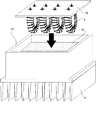
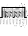
以下、この発明の実施の形態1を図3、図4、図5をもとに説明する。尚室外機における電気品ボックスの配置や室外ファン等の配置は図2に示す従来のものと同様であり、また、従来と同一符号のものは同一または相当するものを示し、その説明を省略する。図3は、この発明のコンバータ装置を示す断面概略図の一例である。図4は、この発明のコンバータ装置を搭載した空気調和機の簡易回路図を示す。図5は、この発明のコンバータ装置の組み立て図である。
【0018】
図3のように、熱伝導性基板14上には、図4に示したコンバータ部の半導体スイッチング素子1およびダイオード16がはんだ付けにより実装されており、熱伝導性基板14を底面として箱状になるように絶縁樹脂のケース17が形成され、放熱手段5と熱伝導性基板14は取り付けネジ18により密着されている。分割され基板実装サイズまで小型化されたリアクトル2は、リアクトル基板19に実装され、熱伝導性基板14の上部に階層的に配置され、基板垂直方向に取り出されたブスバーなどの接続手段により、基板19との固定および電気的な接続を行なっている。
【0019】
さらに、熱伝導性基板14とリアクトル基板19間が熱伝導性および絶縁性の良い樹脂やゲル状の物質15で満たされ、放熱手段5を用いてリアクトル2の熱を放熱できるように構成される。また、樹脂やゲル状の物質にアルミナなどのフィラーを混入することにより、熱伝導性を向上させることも可能である。リアクトル基板19のさらに上層には制御基板21が配置され、半導体スイッチング素子1等が実装され同様にブスバーやコネクタなどの接続手段により接続される。最上部は、絶縁樹脂により密閉され、交流電源入力端子、出力端子、制御用インターフェース端子が外部端子22として取り付けられている。
【0020】
本発明の実施の形態における制御回路は、図4に示したようにリアクトル2が四分割され、半導体スイッチング素子1もリアクトル2にそれぞれ接続された構成となっている。入力電流がピークで30A程度の空気調和機において、リアクトルを4分割すれば一個当りに流れる電流値がピークで8A以内に抑えられるため、基板実装可能なサイズのリアクトルとなり、汎用品の機械巻きリアクトルも選定でき、リアクトルの使用数が増えても、大電流用リアクトル一個に比べコストも抑えられるというメリットもある。さらに、入力電流値が違う機種毎にリアクトルの使用個数を選択することも可能となる。
【0021】
熱伝導性基板14に実装される半導体スイッチング素子1(MOS-FET)は、十数Aを超える大電流用の面実装タイプの汎用品が少ないため、30Aピークの入力電流に対して図4のように各リアクトル2に個別に、1個ないしは2個並列に半導体スイッチング素子1を設けている。また、熱伝導性基板14には半導体スイッチング素子1の他にも、電流検出用のシャント抵抗23など半導体スイッチング素子1以外の発熱部品や、ゲート抵抗24、温度センサー25など半導体スイッチング素子1の駆動や保護上近傍に配置した方が望ましい部品も実装している。今後、さらに大電流用の面実装半導体スイッチング素子(MOS-FET)が汎用化されるか、50Aクラスまでの汎用品があるIGBT等の半導体スイッチング素子を用いれば、各リアクトルに個別に半導体スイッチング素子を設ける必要がなく、コンバータ部の素子数が減らせ、空いたスペースにインバータ部の半導体スイッチング素子を実装でき、ほぼ同サイズの熱伝導性基板上に空気調和機の主回路がすべて入り、基板の小型化が行なえる。
【0022】
リアクトル基板19は、図5に示したように箱状の絶縁樹脂ケース17の内側に差し込まれた後、熱伝導性および絶縁性の良い樹脂もしくはゲル状の物質が充填される。ゲル状の物質の場合、先に絶縁樹脂ケース17内に充填しておき、後からリアクトル基板19を差し込むことも可能である。また、半導体スイッチング素子1により力率改善を行なうコンバータ装置は、半導体スイッチング素子1が電流および電圧変化を急にするため、高周波の電圧振動が起り、図4に示した主回路部の回路ループをアンテナとして強い放射性ノイズが発生する。本発明のコンバータ装置は、集積化されることにより回路ループが小さくなり、放射ノイズを抑制する。さらにリアクトル2およびコンバータ部の回路を封入する樹脂もしくはゲル状物質15内に、放射ノイズを抑制する効果があるフェライトやアルミナなどのEMC対策材料を混入することで大幅に放射ノイズを抑制できる。
【0023】
リアクトル基板19の上部に配置される制御基板21は、力率改善、高調波抑制および任意の母線電圧となるなるように半導体スイッチング素子1をPWM制御する回路および、外部との制御インターフェース回路を備え、最上部の外部接続端子や半導体スイッチング素子が実装される熱伝導性の良い基板にブスバーやコネクタなどで接続されている。また、制御基板を別に設けず、リアクトル基板上に制御回路を組み込み、熱伝導性の良い基板とリアクトル基板の二段構成のコンバータ装置とすることもできる。
【0024】
また、図7に示す圧縮機31、凝縮熱交換器32、絞り装置33、蒸発熱交換器34が順次接続される冷凍サイクルにおいて、この圧縮機31の駆動モータを制御するコンバータ/インバータ装置に、本発明のコンバータ装置を用いた場合、低騒音、低振動となり、放射ノイズを低減した冷凍サイクル装置とすることができる。特に冷凍サイクルに用いられる冷媒が従来オゾン層を破壊するHCFC系のR22冷媒からオゾン層を破壊しないHFC系のR410AやR407C、R32、さらにはHC系のR600A等のR22よりも高圧な冷媒を用いた場合、圧縮機への入力電力が増加する傾向にあるため、放射ノイズの影響が大きくなるが、本発明のようにリアクトルを複数並列接続することによって、リード線3などの主電流が流れる配線の長さを短くすることが可能になり、放射ノイズを低減し、代替冷媒に好適なコンバータ装置とすることができる。
【0025】
実施の形態2.
以下、この発明の実施の形態2を図6をもとに説明する。図6は、この発明の空気調和機におけるコンバータ装置を示す断面概略図の一例である。
【0026】
図6のように、熱伝導性基板14上に、半導体スイッチング素子1、ダイオード16および、分割され基板実装サイズまで小型化されたリアクトル2を実装し、熱伝導性基板14を底面として箱状になるように絶縁樹脂のケース17が形成され、放熱手段5と熱伝導性基板14は取り付けネジ18により密着されている。熱伝導性基板14上に、熱伝導性および絶縁性の良い樹脂やゲル状の物質15をリアクトル2が隠れるまで満たし、放熱手段5を用いてリアクトル2の熱を放熱できるように構成される。樹脂やゲル状の物質15には実施の形態1と同様にフェライトなどのEMC対策材料を混入することにより放射ノイズを抑制できる。また、アルミナ等の熱伝導性材料を混入することによりリアクトル2の放熱が促進される。リアクトル2の上部には制御基板21が配置され、基板垂直方向に取り出したブスバーなどの接続手段により、基板21の固定および電気的な接続を行なっている。最上部は、絶縁樹脂により密閉され、交流電源入力端子、出力端子、制御用インターフェース端子が外部接続端子22として取り付けることにより、実施の形態1と同様の性能を持つコンバータ装置を得ることができる。
【0027】
【発明の効果】
以上のように、この発明によれば、半導体スイッチング素子により、高調波抑制、力率改善を行うコンバータ装置において、高調波抑制、力率改善用に用いられるリアクトルを、半導体素子などを冷却する放熱手段の近傍に配置するとともに、熱伝導性および絶縁性が良い樹脂やゲル状の物質などで封入することで、熱伝導によりリアクトルを前記放熱手段により冷却することができ、リアクトルの配置制約を緩和し、電気品ボックスの温度上昇を抑制することができる。また、温度上昇によるリアクトルの半田付け部の劣化も予防できる。
【0028】
さらに、リアクトルを少なくとも2個以上の並列接続としたことで、リアクトル一個当りに流れる電流ピーク値が抑えられ、基板実装可能なサイズかつ、汎用品のリアクトルとすることができるため、主回路の小型化による放射ノイズの抑制およびコストを低減することができる。
【0029】
また、熱伝導性が良く、絶縁性を持たせた樹脂やゲル状の物質に、熱伝導性を向上させる材料を混入したので、リアクトルの放熱性を向上させることができる。
【0030】
また、熱伝導性が良く、絶縁性を持たせた樹脂やゲル状の物質に、EMC対策材料を混入することにより、主回路の小型化と合せて放射ノイズを大幅に抑制することができる。
【0031】
半導体素子が実装される放熱性の良い基板上に、温度検出手段を備えたことにより、半導体素子の熱破壊に対する保護を行なう事ができる。
【0032】
半導体素子などが実装される熱伝導性基板上もしくは基板近傍に並列接続して配置されるとともに、高調波抑制、力率改善用に用いられるリアクトルを有し、半導体スイッチング素子により、高調波抑制、力率改善を行なうコンバータ装置を備え、冷媒としてR22よりも高圧の冷媒を用いたものでは、高圧の代替冷媒の使用によって圧縮機の入力電力が大きくなっても、放射ノイズの小さな冷凍サイクル装置とすることができる。
【図面の簡単な説明】
【図1】従来の空気調和機のコンバータ装置を示す簡易回路図である。
【図2】従来の空気調和機のコンバータ装置のリアクトル実装状態を、室外機上方から見た図である。
【図3】この発明の実施の形態1によるコンバータ装置の断面概略図である。
【図4】この発明の実施の形態1によるコンバータ装置の簡易回路図である。
【図5】この発明の実施の形態1によるコンバータ装置の組み立て図である。
【図6】この発明の実施の形態2によるコンバータ装置の断面概略図である。
【図7】冷凍サイクル装置を示すシステム概念図である。
【符号の説明】
1.半導体スイッチング素子、2.リアクトル、3.リード線、4.主回路基板、5.放熱手段、6.室外ファン、7.室外機、8.熱交換器、9.電気品ボックス、10.ファンからの直接の風、11.通風孔、12.圧力差により流れる僅かな風、13.電界コンデンサ、14.熱伝導性基板、15.樹脂やゲル状の物質、16.ダイオード、17.絶縁樹脂のケース、18.取付けネジ、19.リアクトル基板、20.接続手段、21.制御基板、22.外部端子、23.シャント抵抗、24.ゲート抵抗、25.温度センサー。[0001]
BACKGROUND OF THE INVENTION
The present invention relates to an air conditioner including a converter device that suppresses harmonics and improves power factor by a semiconductor switching element.
[0002]
[Prior art]
A reactor mounting method and a cooling method for a converter device in a conventional air conditioner will be described with reference to FIGS. 1 and 2. FIG. 1 is a simplified circuit diagram of an air conditioner including a converter device that suppresses harmonics and improves a power factor by a conventional semiconductor switching element. FIG. 2 illustrates a reactor mounted state of a converter device in a conventional air conditioner, and is a cross-sectional view of the outdoor unit of the air conditioner as viewed from above.
[0003]
In FIG. 1, 1 is a semiconductor switching element, 2 is a reactor for suppressing harmonics and power factor improvement, 3 is a lead wire for electrically connecting the
[0004]
In the
[0005]
[Problems to be solved by the invention]
Since the reactor of the converter apparatus in the conventional air conditioner has a large calorific value, it has a structural design restriction that a ventilation path must be secured or placed in a place where ventilation is easily obtained. The outdoor unit of the air conditioner has a configuration in which an outdoor fan 6, a
[0006]
Therefore, for devices that require a control device to be built in a small electrical box such as an air conditioner, the size of the reactor is limited and it can only be placed in the immediate vicinity of the ventilation hole. As a result, there was a problem that the temperature of the product increased, parts such as the electric field capacitor on the control board deteriorated, and the product life decreased. Although it may be possible to suppress the temperature rise inside the box by mounting the reactor outside the electrical box, there are problems such as long lead wires, process variations and poor productivity, and high-pressure parts are easily exposed to dust and moisture. there were.
[0007]
Further, since the power factor improving converter device represented by the circuit as shown in FIG. 2 performs PWM control of the
[0008]
This invention was made to solve the above problems, and by dividing the reactor and connecting it in parallel, it was downsized to a size that can be mounted on a board, and the heat dissipating means actively dissipates it. The purpose is to alleviate the structural constraints and suppress the temperature rise in the electrical box. It is another object of the present invention to reduce processing variations and radiation noise by shortening the lead wire or using leadless.
[0009]
[Means for Solving the Problems]
An air conditioner according to the present invention includes at least two or more parallel-connected reactors used for harmonic suppression and power factor improvement, one or more semiconductor switching elements connected to the reactor, and the semiconductor A heat dissipating means for cooling the switching element, and the reactor is disposed in the vicinity of the heat dissipating means, and the space between the reactor and the heat dissipating means is sealed with a resin or gel-like substance having good thermal conductivity and insulation. Thus, a converter device that cools the reactor by the heat radiating means by heat conduction is provided , and an HFC refrigerant or an HC refrigerant that is a refrigerant having a pressure higher than that of R22 is used as the refrigerant.
[0011]
In addition, a resin or gel-like substance having good thermal conductivity and insulation is mixed with a material that improves thermal conductivity .
[0012]
Also, an EMC countermeasure material is mixed into the resin or gel material having good thermal conductivity and insulation .
[0016]
DETAILED DESCRIPTION OF THE INVENTION
The converter device in the air conditioner according to the present invention is configured by dividing the reactor and connecting them in parallel to reduce the individual size to a size that can be mounted on a board, and connecting to the main circuit board in a leadless manner. Enables reduction of processing variation. Furthermore, the heat dissipation of the semiconductor switching element is achieved by enclosing the reactor and a heat conductive substrate having a heat dissipation means on which the semiconductor switching element is mounted with a resin or gel material having good heat conductivity and insulation. The reactor is also cooled using the means. In addition, radiation generated from the circuit loop of the enclosed power factor correction converter device can be obtained by mixing EMC (Electric Magnetic Compatibility) countermeasure materials or materials that improve thermal conductivity into the resin or gel material that encapsulates the reactor. Noise can be reduced and heat dissipation can be improved.
[0017]
The first embodiment of the present invention will be described below with reference to FIGS. 3, 4, and 5. FIG. The arrangement of the electric box and the outdoor fan in the outdoor unit is the same as that of the conventional apparatus shown in FIG. 2, and the same reference numerals as those of the conventional apparatus indicate the same or corresponding elements, and the description thereof is omitted. . FIG. 3 is an example of a schematic cross-sectional view showing the converter device of the present invention. FIG. 4 shows a simplified circuit diagram of an air conditioner equipped with the converter device of the present invention. FIG. 5 is an assembly view of the converter device of the present invention.
[0018]
As shown in FIG. 3, the
[0019]
Further, the space between the heat
[0020]
In the control circuit according to the embodiment of the present invention, as shown in FIG. 4, the
[0021]
Since the semiconductor switching element 1 (MOS-FET) mounted on the heat
[0022]
As shown in FIG. 5, the
[0023]
The
[0024]
Further, in the refrigeration cycle in which the
[0025]
The second embodiment of the present invention will be described below with reference to FIG. FIG. 6 is an example of a schematic cross-sectional view showing the converter device in the air conditioner of the present invention.
[0026]
As shown in FIG. 6, the
[0027]
【The invention's effect】
As described above, according to the present invention, in a converter device that performs harmonic suppression and power factor improvement using a semiconductor switching element, the reactor used for harmonic suppression and power factor improvement is radiated to cool the semiconductor element and the like. as well as arranged in the vicinity of the unit, to encapsulate by heat conductivity and insulating properties good resin or gel-like substance, a reactor by heat conduction can be cooled by the heat dissipating unit, alleviate the placement constraints of the reactor And the temperature rise of an electrical component box can be suppressed. Further, it is possible to prevent deterioration of the soldering portion of the reactor due to temperature rise.
[0028]
Furthermore, by connecting at least two reactors in parallel, the peak current that flows per reactor can be suppressed, and the size can be mounted on a board and the reactor can be a general-purpose product. It is possible to reduce radiation noise and cost due to the conversion.
[0029]
Moreover, since the material which improves heat conductivity was mixed in the resin and gel-like substance which had favorable heat conductivity and had insulation, the heat dissipation of a reactor can be improved.
[0030]
In addition, by mixing EMC countermeasure material into a resin or gel material having good thermal conductivity and insulation, radiation noise can be significantly suppressed in combination with downsizing of the main circuit.
[0031]
By providing the temperature detecting means on the substrate with good heat dissipation on which the semiconductor element is mounted, it is possible to protect the semiconductor element against thermal destruction.
[0032]
It is arranged in parallel connection on or near the thermally conductive substrate on which the semiconductor element is mounted, and has a reactor used for harmonic suppression and power factor improvement, with the semiconductor switching element, harmonic suppression, In the case of using a converter device that improves the power factor and uses a refrigerant having a pressure higher than R22 as the refrigerant, even if the input power of the compressor increases due to the use of a high-pressure alternative refrigerant, can do.
[Brief description of the drawings]
FIG. 1 is a simplified circuit diagram showing a converter device of a conventional air conditioner.
FIG. 2 is a view of a reactor mounted state of a converter device of a conventional air conditioner as viewed from above the outdoor unit.
FIG. 3 is a schematic cross-sectional view of the converter device according to the first embodiment of the present invention.
FIG. 4 is a simplified circuit diagram of a converter device according to
FIG. 5 is an assembly diagram of the converter device according to the first embodiment of the invention.
FIG. 6 is a schematic sectional view of a converter device according to a second embodiment of the present invention.
FIG. 7 is a system conceptual diagram showing a refrigeration cycle apparatus.
[Explanation of symbols]
1. 1. semiconductor switching element; 2. reactor, 3. Lead wire, 4. main circuit board; 5. heat dissipating means; 6. outdoor fan, Outdoor unit, 8. 8. heat exchanger, Electrical box, 10. Direct wind from the fans, 11. Ventilation holes, 12. A slight wind flowing due to pressure difference, 13. Electric field capacitor, 14. A thermally conductive substrate, 15. Resin or gel-like substance, 16. Diode, 17. 17. Insulating resin case Mounting screws, 19. Reactor board, 20. Connecting means, 21. Control board, 22. External terminal, 23. Shunt resistor, 24. Gate resistance, 25. Temperature sensor.
Claims (3)
冷媒としてR22よりも高圧な冷媒であるHFC系冷媒又はHC系冷媒を用いることを特徴とする空気調和機。At least two or more reactors connected in parallel used for harmonic suppression and power factor improvement, one or more semiconductor switching elements connected to the reactor, and heat dissipation means for cooling the semiconductor switching elements And placing the reactor in the vicinity of the heat radiating means, and encapsulating the reactor and the heat radiating means with a resin or a gel-like substance having good thermal conductivity and insulation, so that the reactor is thermally conductive. A converter device for cooling by the heat dissipating means ;
An air conditioner using an HFC refrigerant or an HC refrigerant, which is a refrigerant having a pressure higher than that of R22, as the refrigerant .
Priority Applications (7)
| Application Number | Priority Date | Filing Date | Title |
|---|---|---|---|
| JP2000086329A JP4581175B2 (en) | 2000-03-27 | 2000-03-27 | Air conditioner |
| EP08002429.2A EP1921737B1 (en) | 2000-03-27 | 2001-03-13 | Single-Phase converter circuit, converter apparatus and the refrigeration cycle apparatus |
| EP01912304A EP1198058B1 (en) | 2000-03-27 | 2001-03-13 | Single-phase ac-dc converter |
| PCT/JP2001/001952 WO2001073933A1 (en) | 2000-03-27 | 2001-03-13 | Single-phase converter, converter and refrigeration cycle device |
| ES08002429.2T ES2612002T3 (en) | 2000-03-27 | 2001-03-13 | Single phase converter circuit, converter device and refrigeration cycle device |
| CNB018006523A CN1265539C (en) | 2000-03-27 | 2001-03-13 | Single-phase converter loop converter and refrigeration cycle device |
| ES01912304T ES2383553T3 (en) | 2000-03-27 | 2001-03-13 | Single phase AC / DC converter |
Applications Claiming Priority (1)
| Application Number | Priority Date | Filing Date | Title |
|---|---|---|---|
| JP2000086329A JP4581175B2 (en) | 2000-03-27 | 2000-03-27 | Air conditioner |
Publications (3)
| Publication Number | Publication Date |
|---|---|
| JP2001275360A JP2001275360A (en) | 2001-10-05 |
| JP2001275360A5 JP2001275360A5 (en) | 2006-10-12 |
| JP4581175B2 true JP4581175B2 (en) | 2010-11-17 |
Family
ID=18602519
Family Applications (1)
| Application Number | Title | Priority Date | Filing Date |
|---|---|---|---|
| JP2000086329A Expired - Fee Related JP4581175B2 (en) | 2000-03-27 | 2000-03-27 | Air conditioner |
Country Status (1)
| Country | Link |
|---|---|
| JP (1) | JP4581175B2 (en) |
Families Citing this family (12)
| Publication number | Priority date | Publication date | Assignee | Title |
|---|---|---|---|---|
| JP2005237141A (en) * | 2004-02-20 | 2005-09-02 | Toyota Motor Corp | Inverter and inverter manufacturing method |
| JP4572571B2 (en) * | 2004-05-07 | 2010-11-04 | トヨタ自動車株式会社 | Electrical equipment housing |
| JP4617719B2 (en) * | 2004-05-14 | 2011-01-26 | ダイキン工業株式会社 | Air conditioner outdoor unit |
| JP2007163012A (en) * | 2005-12-13 | 2007-06-28 | Toshiba Kyaria Kk | Outdoor unit of refrigerating cycle device |
| JP4937326B2 (en) * | 2009-09-30 | 2012-05-23 | 三菱電機株式会社 | Power module |
| JP5499755B2 (en) * | 2010-02-22 | 2014-05-21 | ダイキン工業株式会社 | Switching power supply circuit |
| JP5842905B2 (en) * | 2013-12-24 | 2016-01-13 | ダイキン工業株式会社 | Refrigeration equipment |
| JP6064943B2 (en) * | 2014-05-09 | 2017-01-25 | 株式会社豊田自動織機 | Electronics |
| JP6190851B2 (en) * | 2015-07-30 | 2017-08-30 | 三菱電機株式会社 | Power converter |
| JP6954176B2 (en) * | 2018-02-21 | 2021-10-27 | トヨタ自動車株式会社 | unit |
| JP7233026B2 (en) * | 2018-04-25 | 2023-03-06 | パナソニックIpマネジメント株式会社 | power supply |
| CN111578411A (en) * | 2020-04-24 | 2020-08-25 | 罗辉 | Air conditioner for subway station |
Citations (12)
| Publication number | Priority date | Publication date | Assignee | Title |
|---|---|---|---|---|
| JPH03289358A (en) * | 1990-04-02 | 1991-12-19 | Toshiba Corp | Ac/dc converter |
| JPH0413766A (en) * | 1990-05-02 | 1992-01-17 | Siegel:Kk | Composite-type silicone gel material and production thereof |
| JPH06123449A (en) * | 1992-10-12 | 1994-05-06 | Hitachi Ltd | Outdoor device of air conditioner |
| JPH07177760A (en) * | 1993-12-20 | 1995-07-14 | Toshiba Corp | Inverter device |
| JPH08274482A (en) * | 1995-03-29 | 1996-10-18 | Mitsubishi Electric Corp | Control board |
| JPH1098140A (en) * | 1996-09-24 | 1998-04-14 | Hitachi Ltd | Multiple-chip type semiconductor device |
| JPH10205830A (en) * | 1997-01-22 | 1998-08-04 | Mitsubishi Electric Corp | Inverter control circuit apparatus for air conditioning equipment |
| JPH10311646A (en) * | 1997-05-13 | 1998-11-24 | Matsushita Refrig Co Ltd | Control device of refrigerator |
| JPH10337031A (en) * | 1997-05-30 | 1998-12-18 | Toshiba Corp | Dc power supply equipment |
| JPH1169861A (en) * | 1997-08-07 | 1999-03-09 | Toshiba Corp | Motor control device, freezing cycle device and air conditioner using the motor control device |
| JPH11204952A (en) * | 1998-01-14 | 1999-07-30 | Toyo Electric Mfg Co Ltd | Electric apparatus housing box |
| JPH11354958A (en) * | 1998-06-10 | 1999-12-24 | Hitachi Ltd | Control unit for vehicle |
-
2000
- 2000-03-27 JP JP2000086329A patent/JP4581175B2/en not_active Expired - Fee Related
Patent Citations (12)
| Publication number | Priority date | Publication date | Assignee | Title |
|---|---|---|---|---|
| JPH03289358A (en) * | 1990-04-02 | 1991-12-19 | Toshiba Corp | Ac/dc converter |
| JPH0413766A (en) * | 1990-05-02 | 1992-01-17 | Siegel:Kk | Composite-type silicone gel material and production thereof |
| JPH06123449A (en) * | 1992-10-12 | 1994-05-06 | Hitachi Ltd | Outdoor device of air conditioner |
| JPH07177760A (en) * | 1993-12-20 | 1995-07-14 | Toshiba Corp | Inverter device |
| JPH08274482A (en) * | 1995-03-29 | 1996-10-18 | Mitsubishi Electric Corp | Control board |
| JPH1098140A (en) * | 1996-09-24 | 1998-04-14 | Hitachi Ltd | Multiple-chip type semiconductor device |
| JPH10205830A (en) * | 1997-01-22 | 1998-08-04 | Mitsubishi Electric Corp | Inverter control circuit apparatus for air conditioning equipment |
| JPH10311646A (en) * | 1997-05-13 | 1998-11-24 | Matsushita Refrig Co Ltd | Control device of refrigerator |
| JPH10337031A (en) * | 1997-05-30 | 1998-12-18 | Toshiba Corp | Dc power supply equipment |
| JPH1169861A (en) * | 1997-08-07 | 1999-03-09 | Toshiba Corp | Motor control device, freezing cycle device and air conditioner using the motor control device |
| JPH11204952A (en) * | 1998-01-14 | 1999-07-30 | Toyo Electric Mfg Co Ltd | Electric apparatus housing box |
| JPH11354958A (en) * | 1998-06-10 | 1999-12-24 | Hitachi Ltd | Control unit for vehicle |
Also Published As
| Publication number | Publication date |
|---|---|
| JP2001275360A (en) | 2001-10-05 |
Similar Documents
| Publication | Publication Date | Title |
|---|---|---|
| US6501662B2 (en) | Motor driving inverter | |
| US7848104B2 (en) | Power module | |
| JP3501685B2 (en) | Power converter | |
| EP1843453B1 (en) | Rotary electric machine | |
| JP5861614B2 (en) | High voltage electric device and electric compressor | |
| JP4581175B2 (en) | Air conditioner | |
| JP4698621B2 (en) | Motor with built-in power conversion circuit and equipment equipped with it | |
| US6115270A (en) | Electric power conversion assembly with ceramic smoothing capacitor | |
| US20180191220A1 (en) | Electric compressor | |
| JP2002204580A (en) | Power converter | |
| WO2001073933A1 (en) | Single-phase converter, converter and refrigeration cycle device | |
| JP2004039749A (en) | Multi-phase inverter module | |
| JP3529675B2 (en) | Semiconductor device and inverter device | |
| CN110085581B (en) | High-integration intelligent power module and air conditioner | |
| JP2000058746A (en) | Device for cooling inside of module | |
| CN211650663U (en) | Electric control assembly and air conditioner | |
| JP2005020803A (en) | Control unit, control unit for compressor, and compressor | |
| EP3012958A1 (en) | Power conversion device | |
| JP5345124B2 (en) | Air conditioner equipped with a motor with built-in power conversion circuit | |
| JP3566505B2 (en) | Inverter device | |
| JP2011181824A (en) | Power semiconductor device and ac power generator for vehicle | |
| CN112087151A (en) | Intelligent power module and air conditioner | |
| JP2002094246A (en) | Multi-layer printed wiring board and method for packaging the same | |
| JP6934985B1 (en) | Rotating machine | |
| CN210840224U (en) | Electric control assembly and air conditioner |
Legal Events
| Date | Code | Title | Description |
|---|---|---|---|
| RD01 | Notification of change of attorney |
Free format text: JAPANESE INTERMEDIATE CODE: A7421 Effective date: 20040629 |
|
| A521 | Written amendment |
Free format text: JAPANESE INTERMEDIATE CODE: A523 Effective date: 20060830 |
|
| A621 | Written request for application examination |
Free format text: JAPANESE INTERMEDIATE CODE: A621 Effective date: 20060830 |
|
| A131 | Notification of reasons for refusal |
Free format text: JAPANESE INTERMEDIATE CODE: A131 Effective date: 20090915 |
|
| A521 | Written amendment |
Free format text: JAPANESE INTERMEDIATE CODE: A523 Effective date: 20091112 |
|
| A02 | Decision of refusal |
Free format text: JAPANESE INTERMEDIATE CODE: A02 Effective date: 20100330 |
|
| A521 | Written amendment |
Free format text: JAPANESE INTERMEDIATE CODE: A523 Effective date: 20100622 |
|
| A911 | Transfer of reconsideration by examiner before appeal (zenchi) |
Free format text: JAPANESE INTERMEDIATE CODE: A911 Effective date: 20100701 |
|
| TRDD | Decision of grant or rejection written | ||
| A01 | Written decision to grant a patent or to grant a registration (utility model) |
Free format text: JAPANESE INTERMEDIATE CODE: A01 Effective date: 20100803 |
|
| A01 | Written decision to grant a patent or to grant a registration (utility model) |
Free format text: JAPANESE INTERMEDIATE CODE: A01 |
|
| A61 | First payment of annual fees (during grant procedure) |
Free format text: JAPANESE INTERMEDIATE CODE: A61 Effective date: 20100816 |
|
| R151 | Written notification of patent or utility model registration |
Ref document number: 4581175 Country of ref document: JP Free format text: JAPANESE INTERMEDIATE CODE: R151 |
|
| FPAY | Renewal fee payment (event date is renewal date of database) |
Free format text: PAYMENT UNTIL: 20130910 Year of fee payment: 3 |
|
| R250 | Receipt of annual fees |
Free format text: JAPANESE INTERMEDIATE CODE: R250 |
|
| R250 | Receipt of annual fees |
Free format text: JAPANESE INTERMEDIATE CODE: R250 |
|
| R250 | Receipt of annual fees |
Free format text: JAPANESE INTERMEDIATE CODE: R250 |
|
| R250 | Receipt of annual fees |
Free format text: JAPANESE INTERMEDIATE CODE: R250 |
|
| LAPS | Cancellation because of no payment of annual fees |