JP4579231B2 - Floor board and manufacturing method thereof - Google Patents
Floor board and manufacturing method thereof Download PDFInfo
- Publication number
- JP4579231B2 JP4579231B2 JP2006502812A JP2006502812A JP4579231B2 JP 4579231 B2 JP4579231 B2 JP 4579231B2 JP 2006502812 A JP2006502812 A JP 2006502812A JP 2006502812 A JP2006502812 A JP 2006502812A JP 4579231 B2 JP4579231 B2 JP 4579231B2
- Authority
- JP
- Japan
- Prior art keywords
- floorboard
- surface layer
- floor
- core
- floorboards
- Prior art date
- Legal status (The legal status is an assumption and is not a legal conclusion. Google has not performed a legal analysis and makes no representation as to the accuracy of the status listed.)
- Expired - Fee Related
Links
Images


Classifications
-
- B—PERFORMING OPERATIONS; TRANSPORTING
- B32—LAYERED PRODUCTS
- B32B—LAYERED PRODUCTS, i.e. PRODUCTS BUILT-UP OF STRATA OF FLAT OR NON-FLAT, e.g. CELLULAR OR HONEYCOMB, FORM
- B32B21/00—Layered products comprising a layer of wood, e.g. wood board, veneer, wood particle board
- B32B21/10—Next to a fibrous or filamentary layer
-
- A—HUMAN NECESSITIES
- A47—FURNITURE; DOMESTIC ARTICLES OR APPLIANCES; COFFEE MILLS; SPICE MILLS; SUCTION CLEANERS IN GENERAL
- A47G—HOUSEHOLD OR TABLE EQUIPMENT
- A47G27/00—Floor fabrics; Fastenings therefor
- A47G27/02—Carpets; Stair runners; Bedside rugs; Foot mats
-
- A—HUMAN NECESSITIES
- A47—FURNITURE; DOMESTIC ARTICLES OR APPLIANCES; COFFEE MILLS; SPICE MILLS; SUCTION CLEANERS IN GENERAL
- A47G—HOUSEHOLD OR TABLE EQUIPMENT
- A47G27/00—Floor fabrics; Fastenings therefor
- A47G27/02—Carpets; Stair runners; Bedside rugs; Foot mats
- A47G27/0293—Mat modules for interlocking engagement
-
- B—PERFORMING OPERATIONS; TRANSPORTING
- B27—WORKING OR PRESERVING WOOD OR SIMILAR MATERIAL; NAILING OR STAPLING MACHINES IN GENERAL
- B27F—DOVETAILED WORK; TENONS; SLOTTING MACHINES FOR WOOD OR SIMILAR MATERIAL; NAILING OR STAPLING MACHINES
- B27F1/00—Dovetailed work; Tenons; Making tongues or grooves; Groove- and- tongue jointed work; Finger- joints
- B27F1/02—Making tongues or grooves, of indefinite length
- B27F1/04—Making tongues or grooves, of indefinite length along only one edge of a board
-
- B—PERFORMING OPERATIONS; TRANSPORTING
- B27—WORKING OR PRESERVING WOOD OR SIMILAR MATERIAL; NAILING OR STAPLING MACHINES IN GENERAL
- B27F—DOVETAILED WORK; TENONS; SLOTTING MACHINES FOR WOOD OR SIMILAR MATERIAL; NAILING OR STAPLING MACHINES
- B27F1/00—Dovetailed work; Tenons; Making tongues or grooves; Groove- and- tongue jointed work; Finger- joints
- B27F1/02—Making tongues or grooves, of indefinite length
- B27F1/06—Making tongues or grooves, of indefinite length simultaneously along opposite edges of a board
-
- B—PERFORMING OPERATIONS; TRANSPORTING
- B27—WORKING OR PRESERVING WOOD OR SIMILAR MATERIAL; NAILING OR STAPLING MACHINES IN GENERAL
- B27M—WORKING OF WOOD NOT PROVIDED FOR IN SUBCLASSES B27B - B27L; MANUFACTURE OF SPECIFIC WOODEN ARTICLES
- B27M3/00—Manufacture or reconditioning of specific semi-finished or finished articles
- B27M3/04—Manufacture or reconditioning of specific semi-finished or finished articles of flooring elements, e.g. parqueting blocks
-
- B—PERFORMING OPERATIONS; TRANSPORTING
- B27—WORKING OR PRESERVING WOOD OR SIMILAR MATERIAL; NAILING OR STAPLING MACHINES IN GENERAL
- B27M—WORKING OF WOOD NOT PROVIDED FOR IN SUBCLASSES B27B - B27L; MANUFACTURE OF SPECIFIC WOODEN ARTICLES
- B27M3/00—Manufacture or reconditioning of specific semi-finished or finished articles
- B27M3/08—Manufacture or reconditioning of specific semi-finished or finished articles of specially shaped wood laths or strips
-
- B—PERFORMING OPERATIONS; TRANSPORTING
- B32—LAYERED PRODUCTS
- B32B—LAYERED PRODUCTS, i.e. PRODUCTS BUILT-UP OF STRATA OF FLAT OR NON-FLAT, e.g. CELLULAR OR HONEYCOMB, FORM
- B32B3/00—Layered products comprising a layer with external or internal discontinuities or unevennesses, or a layer of non-planar form; Layered products having particular features of form
- B32B3/02—Layered products comprising a layer with external or internal discontinuities or unevennesses, or a layer of non-planar form; Layered products having particular features of form characterised by features of form at particular places, e.g. in edge regions
- B32B3/06—Layered products comprising a layer with external or internal discontinuities or unevennesses, or a layer of non-planar form; Layered products having particular features of form characterised by features of form at particular places, e.g. in edge regions for securing layers together; for attaching the product to another member, e.g. to a support, or to another product, e.g. groove/tongue, interlocking
-
- E—FIXED CONSTRUCTIONS
- E04—BUILDING
- E04F—FINISHING WORK ON BUILDINGS, e.g. STAIRS, FLOORS
- E04F15/00—Flooring
- E04F15/02—Flooring or floor layers composed of a number of similar elements
-
- E—FIXED CONSTRUCTIONS
- E04—BUILDING
- E04F—FINISHING WORK ON BUILDINGS, e.g. STAIRS, FLOORS
- E04F15/00—Flooring
- E04F15/02—Flooring or floor layers composed of a number of similar elements
- E04F15/02038—Flooring or floor layers composed of a number of similar elements characterised by tongue and groove connections between neighbouring flooring elements
-
- B—PERFORMING OPERATIONS; TRANSPORTING
- B32—LAYERED PRODUCTS
- B32B—LAYERED PRODUCTS, i.e. PRODUCTS BUILT-UP OF STRATA OF FLAT OR NON-FLAT, e.g. CELLULAR OR HONEYCOMB, FORM
- B32B2307/00—Properties of the layers or laminate
- B32B2307/10—Properties of the layers or laminate having particular acoustical properties
- B32B2307/102—Insulating
-
- B—PERFORMING OPERATIONS; TRANSPORTING
- B32—LAYERED PRODUCTS
- B32B—LAYERED PRODUCTS, i.e. PRODUCTS BUILT-UP OF STRATA OF FLAT OR NON-FLAT, e.g. CELLULAR OR HONEYCOMB, FORM
- B32B2307/00—Properties of the layers or laminate
- B32B2307/50—Properties of the layers or laminate having particular mechanical properties
- B32B2307/558—Impact strength, toughness
-
- B—PERFORMING OPERATIONS; TRANSPORTING
- B32—LAYERED PRODUCTS
- B32B—LAYERED PRODUCTS, i.e. PRODUCTS BUILT-UP OF STRATA OF FLAT OR NON-FLAT, e.g. CELLULAR OR HONEYCOMB, FORM
- B32B2471/00—Floor coverings
-
- E—FIXED CONSTRUCTIONS
- E04—BUILDING
- E04F—FINISHING WORK ON BUILDINGS, e.g. STAIRS, FLOORS
- E04F15/00—Flooring
- E04F15/02—Flooring or floor layers composed of a number of similar elements
- E04F15/04—Flooring or floor layers composed of a number of similar elements only of wood or with a top layer of wood, e.g. with wooden or metal connecting members
-
- E—FIXED CONSTRUCTIONS
- E04—BUILDING
- E04F—FINISHING WORK ON BUILDINGS, e.g. STAIRS, FLOORS
- E04F2201/00—Joining sheets or plates or panels
- E04F2201/01—Joining sheets, plates or panels with edges in abutting relationship
- E04F2201/0153—Joining sheets, plates or panels with edges in abutting relationship by rotating the sheets, plates or panels around an axis which is parallel to the abutting edges, possibly combined with a sliding movement
-
- E—FIXED CONSTRUCTIONS
- E04—BUILDING
- E04F—FINISHING WORK ON BUILDINGS, e.g. STAIRS, FLOORS
- E04F2201/00—Joining sheets or plates or panels
- E04F2201/02—Non-undercut connections, e.g. tongue and groove connections
- E04F2201/023—Non-undercut connections, e.g. tongue and groove connections with a continuous tongue or groove
-
- E—FIXED CONSTRUCTIONS
- E04—BUILDING
- E04F—FINISHING WORK ON BUILDINGS, e.g. STAIRS, FLOORS
- E04F2201/00—Joining sheets or plates or panels
- E04F2201/02—Non-undercut connections, e.g. tongue and groove connections
- E04F2201/026—Non-undercut connections, e.g. tongue and groove connections with rabbets, e.g. being stepped
-
- E—FIXED CONSTRUCTIONS
- E04—BUILDING
- E04F—FINISHING WORK ON BUILDINGS, e.g. STAIRS, FLOORS
- E04F2201/00—Joining sheets or plates or panels
- E04F2201/03—Undercut connections, e.g. using undercut tongues or grooves
-
- E—FIXED CONSTRUCTIONS
- E04—BUILDING
- E04F—FINISHING WORK ON BUILDINGS, e.g. STAIRS, FLOORS
- E04F2201/00—Joining sheets or plates or panels
- E04F2201/05—Separate connectors or inserts, e.g. pegs, pins, keys or strips
-
- E—FIXED CONSTRUCTIONS
- E04—BUILDING
- E04F—FINISHING WORK ON BUILDINGS, e.g. STAIRS, FLOORS
- E04F2201/00—Joining sheets or plates or panels
- E04F2201/05—Separate connectors or inserts, e.g. pegs, pins, keys or strips
- E04F2201/0517—U- or C-shaped brackets and clamps
Abstract
Description
本発明は、全体として、フロアボードの技術分野に関する。本発明は様々なパターンで機械的に接合できる、繊維でできた吸音性表面を持つフロアボードに関する。本発明は、更に、このようなフロアボードの製造方法に関する。本発明は、フローティングフロアで使用するのに特に適している。 The present invention relates generally to the technical field of floorboards. The present invention relates to a floorboard having a sound absorbing surface made of fibers that can be mechanically joined in various patterns. The invention further relates to a method for manufacturing such a floorboard. The present invention is particularly suitable for use on a floating floor.
本発明は、機械式接合システムを持つフローティングフロアで使用するのに特に適している。このようなフロアは、多くの場合、積層体又は木材でできた表面層、コア、及びバランシング層を含み、機械的に、即ち接着剤を用いないで、長側部及び短側部の両方に沿って垂直方向及び水平方向で接合されるようになった矩形フロアボードとして形成される。 The present invention is particularly suitable for use on a floating floor with a mechanical joining system. Such floors often include surface layers, cores and balancing layers made of laminate or wood, both mechanically, i.e. without adhesives, on both the long and short sides. It is formed as a rectangular floorboard that is adapted to be joined along the vertical and horizontal directions.
従って、従来技術、周知のシステムの問題点、並びに本発明の目的及び特徴の以下の説明は、非限定的例として、主にこの適用分野と関連している。しかしながら、本発明は、表面層及びコアを持つ随意のフロアボードで使用できるということを強調しておかなければならない。かくして、本発明は、ベースに釘付け又は接着されるフロアにも適用できる。 Accordingly, the following description of the prior art, known system problems, and objects and features of the present invention is primarily related to this field of application as a non-limiting example. However, it should be emphasized that the present invention can be used with any floorboard having a surface layer and a core. Thus, the present invention is also applicable to floors that are nailed or glued to the base.
機械式接合システム及び積層体又は木材でできた表面を持つフローティングフロアが、近年、例えばカーペットやプラスチックフローリングばかりでなく、ベースに接着される木製フローリングから市場を大きく奪ってきた。一つの理由は、完全に滑らかであったり平らであったりしない下張り床にこれらのフロアを手早く且つ容易に敷設できることである。これらのフロアボードは、下張り床から自由に移動できる。ベースボードの下及びフロアボード間の接合部で生じる収縮及び膨張が重要である。機械式接合システムを持つフローティングフロアは、容易に取り外すことができ、再び敷設できる。個々のフロアボードを交換でき、更新を行うために下張り床にアクセスでき、フロア全体を別の部屋に移動できる。 Floating floors with mechanical joining systems and laminate or wood surfaces have recently taken the market significantly away from, for example, wooden flooring glued to the base as well as carpet and plastic flooring. One reason is that these floors can be laid quickly and easily on a subfloor that is not completely smooth or flat. These floorboards can be moved freely from the subfloor. The shrinkage and expansion that occurs at the joints under the baseboard and between the floorboards is important. A floating floor with a mechanical joining system can be easily removed and laid again. Individual floorboards can be replaced, the subfloor can be accessed for renewal, and the entire floor can be moved to another room.
下張り床に接着されるプラスチックフロア及びテキスタイルフロアカバーは、下張り床が完全に平らであることを必要とする。敷設が面倒であり、フロアを損傷することなく取り外すことはできない。このようなフローリングは、例えば4mの幅で供給できるため、有利である。接合部が少ない。プラスチックフローリングは、水に対して不透過性であり、プラスチックフローリング及びテキスタイルフローリングは両方とも軟質であり、積層体や木製フロアよりも音響レベルが低い。 Plastic floors and textile floor covers that are glued to the underfloor require that the underfloor be completely flat. Laying is cumbersome and cannot be removed without damaging the floor. Such a flooring is advantageous, for example, because it can be supplied in a width of 4 m. There are few joints. Plastic flooring is impermeable to water, and both plastic flooring and textile flooring are soft and have a lower sound level than laminates and wooden floors.
かくして、フローティングフロアは、下張り床に接着されるフロアよりも多くの利点を備えている。しかしながら、木材又は積層体でできた硬質表面を備えたこのようなフローティングフロアの大きな欠点は、人々が床の上を歩くときに大きな音響レベルを発生するということである。この音響レベルは、事務所、ホテル、多くの人が歩き回る仕事場等の公共の場所では無視することができない。音響レベルを減少することができるのであれば、フローティングフロアを更に広く使用することができる。 Thus, a floating floor has many advantages over a floor that is bonded to an underlay floor. However, a major drawback of such a floating floor with a hard surface made of wood or laminate is that people generate large sound levels when walking on the floor. This sound level cannot be ignored in public places such as offices, hotels, and workplaces where many people walk around. If the sound level can be reduced, the floating floor can be used more widely.
以下の説明において、設置したフロアボードの見える方の表面を「前側」と呼ぶのに対し、下張り床に面するフロアボードの反対側を「後側」と呼ぶ。製造で使用されるシート状開始材料を「コア」と呼ぶ。コアの前側の最も近くを表面層でコーティングし、後側の最も近くをバランシング層でコーティングした場合、「フロアパネル」と呼ばれる半製品が形成され、又は続いて行われる作業でこの半製品を上文中で言及した複数のフロアパネルに分割した場合には「フロアエレメント」呼ばれる半製品が形成される。フロアパネルをそれらの縁部に沿って機械加工し、接合システムを持つ最終形状にしたとき、これらは「フロアボード」と呼ばれる。「表面層」という用語は、コアの前側の最も近くに適用され、好ましくはフロアボードの前側全体を覆う全ての層を意味する。「装飾表面層」という用語は、本質的に、フロアにその装飾的外観を提供するようになった層を意味する。「磨耗層」は、主に前側の丈夫さを改善するようになった層に関する。「積層体フローリング」という用語は、この表示で市販されているフローリングを意味する。積層体フローリングの磨耗層は、概して、メラミン樹脂を含浸し、アルミニウム酸化物を添加した透明な紙シートを含む。装飾層は、メラミン含浸装飾紙シートでできている。コアは、概して、木材繊維を基材としたシートである。「HDF」という用語は、高密度ファイバボード、即ちHDFの表示で市場で周知のシート材料を意味する。HDFは、バインダーによって接合された微粉細された木材繊維でできている。HDFシートが低密度で製造された場合、MDF(中密度ファイバボード)と呼ばれる。 In the following description, the surface on which the installed floorboard can be seen is called the “front side”, while the opposite side of the floorboard facing the underfloor floor is called the “rear side”. The sheet-like starting material used in manufacturing is called the “core”. If the front side closest to the core is coated with a surface layer and the back side nearest is coated with a balancing layer, a semi-finished product called a “floor panel” is formed, or the semi-finished product is When divided into a plurality of floor panels mentioned in the text, a semi-finished product called a “floor element” is formed. When floor panels are machined along their edges to a final shape with a bonding system, these are called “floor boards”. The term “surface layer” refers to all layers that are applied closest to the front side of the core and preferably cover the entire front side of the floorboard. The term “decorative surface layer” essentially means a layer adapted to provide its decorative appearance to the floor. “Wear layer” mainly relates to a layer that has been adapted to improve the robustness of the front side. The term “laminate flooring” means a flooring marketed under this designation. The wear layer of laminate flooring generally comprises a transparent paper sheet impregnated with melamine resin and added with aluminum oxide. The decorative layer is made of a melamine-impregnated decorative paper sheet. The core is generally a sheet based on wood fibers. The term “HDF” means a high density fiber board, or sheet material well known in the market for HDF displays. HDF is made of finely divided wood fibers joined by a binder. When the HDF sheet is manufactured at low density, it is called MDF (medium density fiber board).
フロアボードの縁部の前側と後側との間のフロアボードの外部分を「接合縁」と呼ぶ。概して、接合縁は、幾つかの「接合表面」を有する。これらの接合表面は、垂直であったり、水平であったり、傾いていたり、丸味が付けてあったり、面取りが施してあったりする。これらの接合面は、例えば積層体、ファイバボード、木材、プラスチック、金属(特にアルミニウム)等の様々な材料、又はシーリング材料に設けられる。「接合」又は「係止システム」は、フロアボードを垂直方向及び/又は水平方向で連結する協働連結手段を意味する。「機械式係止システム」という用語は、表面と平行に水平方向で及び表面に対して垂直方向で、接着剤なしで接合できるということを意味する。機械式係止システムは、更に、接着剤によって接合できる。「フローティングフロア」という用語は、夫々の接合縁でだけ接合されており、及びかくして下張り床に接着されていないフロアボードでできたフローリングを意味する。水分によって移動が生じた場合でも、接合部は密のままである。水分によって生じる移動は、フロアの外領域で、ベースボードの下に隠された壁に沿って生じる。「テキスタイルフロア」という用語は、互いに接合されてカーペットやフェルトを形成する油性合成繊維又は天然繊維でできた軟質フローリングを意味する。このフローリングは、通常は、約4mの幅及び数百mに達する長さで製造される。このフローリングは、工場から、通常はロールの形態で送出され、通常は、接着剤によって下張り床に設置される。「ニードルフェルト」という用語は、ニードルフェルトカーペットの表示で市販されている、繊維を基材としたフェルトを意味する。フロアは、互いに接合されてフェルトを形成する、例えばポリプロピレン(PP)、ナイロン(PA)、又はポリエステル(PES)でできた油性繊維でできている。接合は、フックを備えたニードルによってパンチされた繊維マットによって行われる。後側は、通常は、ラテックス及びチョークを含むフォームでコーティングされる。 The outer part of the floorboard between the front side and the rear side of the edge of the floorboard is called the “joining edge”. In general, a joining edge has several “joining surfaces”. These joining surfaces may be vertical, horizontal, tilted, rounded, or chamfered. These joining surfaces are provided on various materials such as laminates, fiber boards, wood, plastics, metals (particularly aluminum), or sealing materials. “Joint” or “locking system” means cooperating connection means for connecting floorboards in the vertical and / or horizontal direction. The term “mechanical locking system” means that it can be joined without adhesive in a horizontal direction parallel to the surface and in a direction perpendicular to the surface. The mechanical locking system can also be joined by an adhesive. The term “floating floor” means a flooring made of floorboards that are joined only at their respective joining edges and thus are not glued to the subfloor. Even when movement occurs due to moisture, the joint remains dense. Movement caused by moisture occurs along the wall hidden under the baseboard in the outer area of the floor. The term “textile floor” means a soft flooring made of oily synthetic fibers or natural fibers that are joined together to form a carpet or felt. This flooring is usually produced with a width of about 4 m and a length reaching several hundred m. This flooring is delivered from the factory, usually in the form of a roll, and is usually installed on the subfloor by an adhesive. The term “needle felt” means a fiber-based felt that is commercially available on the needle felt carpet label. The floor is made of oily fibers made of, for example, polypropylene (PP), nylon (PA), or polyester (PES) that are joined together to form a felt. Joining is performed by a fiber mat punched by a needle with a hook. The back side is usually coated with a foam containing latex and chalk.
次に、本発明並びに本発明の背後の問題点の理解及び説明を促すため、従来技術を以下に説明する。下文において長側部及び短側部を持つ矩形状であると説明するフロアボードは、四角形状であってもよい。 Next, in order to facilitate understanding and explanation of the present invention and the problems behind the present invention, the prior art will be described below. The floor board described below as a rectangular shape having a long side portion and a short side portion may have a rectangular shape.
表面が積層体又は木材でできた硬質フローリングは、高い音響レベルを発生する。この高い音響レベルは、主として、人々が積層体又は木材でできた硬質の表面上を歩き回ることによって発生する。表面のところで発生した音により部屋の中に高い音響レベルが発生する。音は、更に、床を通り抜けて梁や接合部に至る。この問題点を解決するため、板紙、フェルト、フォーム、等の材料でできたベースにフローティングフロアが設置されてきた。かくして、フロアボードの後側で発生した音は、フローティングフローリングと下張り床との間に適用された特殊な下敷材料によって減少される。これにより、二つのフロアレベル間の音響レベルを大幅に減衰できる。室内で達成できる音響の減少は、限られている。 Hard flooring with a laminate or wood surface generates a high sound level. This high sound level is mainly caused by people walking around on hard surfaces made of laminates or wood. The sound generated at the surface causes a high sound level in the room. The sound further passes through the floor to the beams and joints. To solve this problem, floating floors have been installed on bases made of paperboard, felt, foam, and other materials. Thus, the sound generated behind the floorboard is reduced by a special underlay material applied between the floating flooring and the subfloor. Thereby, the sound level between two floor levels can be attenuated significantly. The acoustic reduction that can be achieved indoors is limited.
別の音響レベル減少方法は、フロアボードを下張り床に接着する方法である。これにより、室内の音響レベルが或る程度減少し、音響周波数が比較的好ましいと感じられる。費用は高く、敷設品質が劣り、多くの大きな接合部隙間が生じる。第3の方法は、例えばコルクでできた表面層をフロアボードの表面に設けることである。この材料は木材や積層体よりも軟質であり、音響レベルを減少する。しかしながら、コルクフロアには多くの欠点がある。丈夫さ及び跡の付き難さが比較的低く、高価格であり、音響減少が不十分である。 Another method for reducing the sound level is to bond the floorboard to the subfloor. Thereby, the sound level in the room is reduced to some extent, and the sound frequency is felt to be relatively favorable. Cost is high, laying quality is inferior and many large joint gaps are created. The third method is to provide a surface layer made of, for example, cork on the surface of the floorboard. This material is softer than wood and laminates and reduces sound levels. However, the cork floor has many drawbacks. Ruggedness and difficulty of marking are relatively low, expensive, and sound reduction is insufficient.
本発明の目的は、機械的に接合することにより、音響レベルが低いフローティングフローリングを形成できるフロアボードを提供することである。このようなフローリングは、魅力的外観を備えていると同時に高精度に製造できなければならない。 An object of the present invention is to provide a floorboard that can form a floating flooring having a low sound level by mechanical joining. Such flooring must have an attractive appearance and be able to be manufactured with high precision.
本発明は、とりわけ、硬質の材料がその表面に当たったときに高い音響レベルを発生しない表面層を使用して低い音響レベルを提供しなければならないという第1の理解に基づく。 The present invention is based, among other things, on a first understanding that a low acoustic level must be provided using a surface layer that does not generate a high acoustic level when a hard material hits its surface.
本発明は、低密度の軟質表面層を持つフロアボードの音響レベルが、硬質で高密度の表面層を持つフロアボードよりも低いという第2の理解に基づく。 The present invention is based on a second understanding that the sound level of a floorboard with a low density soft surface layer is lower than a floorboard with a hard, high density surface layer.
本発明は、吸音性であり且つ耐久性及び耐衝撃性が高い表面層を低価格で提供できるという第3の理解に基づく。このような表面層は、可撓性であり、荷重が加わったとき、例えば人々が表面上を歩ったときに圧縮できる、繊維でできていなければならない。これらの繊維は、比較的高密度であり且つ非常に強固な材料、例えば合成繊維又は羊毛等の天然繊維で形成できる。繊維が細く、接合されて可撓性繊維間に空気を含むフェルトやカーペットを形成した場合、軟質であり且つ低密度の表面層が形成される。繊維の細さは、例えば、0.05mm乃至0.10mmである。表面層の容積密度は400kg/m3 以下であり、好ましくは150kg/m2 乃至300kg/m2 である。これは、木材、積層体、及びコルクよりもかなり低く、音響レベルはこれらの材料全てよりも大幅に低下する。 The present invention is based on a third understanding that a surface layer that is sound-absorbing and has high durability and impact resistance can be provided at low cost. Such a surface layer must be made of fibers that are flexible and can be compressed when a load is applied, for example when people walk on the surface. These fibers can be formed from relatively dense and very strong materials such as natural fibers such as synthetic fibers or wool. When the fibers are thin and joined to form a felt or carpet containing air between the flexible fibers, a soft and low density surface layer is formed. The fineness of the fiber is, for example, 0.05 mm to 0.10 mm. The volume density of the surface layer is 400 kg / m 3 or less, preferably 150 kg / m 2 to 300 kg / m 2 . This is much lower than wood, laminate, and cork, and the sound level is significantly lower than all these materials.
本発明は、例えばニードルフェルトマットの形態の繊維を基材とした低密度の表面層を例えば接着によって例えばファイバボードのコアに適用できるという第4の非常に驚くべき理解に基づく。コアは、例えばパーティクルボード、MDF、又はHDFであってもよい。このフロアエレメントは、例えば鋸断によってフロアパネルに分割でき、これらのパネルを例えば回転ナイフ及びダイヤモンド工具の組み合わせを使用して機械加工でき、その結果、これらのパネルはフローティングフロアのフロアボードを形成する。上部接合縁は、表面のところで主に自由繊維を含み、コアの近くで繊維がコアに接合されるように形成できる。次いで、表面層を高精度で及び緩い繊維なしで製造できる。コアに近い繊維は、ラテックス等の可撓性材料と混合することによって接合できる。これにより、表面層の安定性を向上し、また、塵埃が表面層の下部分に侵入しないため、清掃が容易になる。表面層が薄いと、この表面層がコアと一体である場合、取り扱いが更に容易になる。 The invention is based on a fourth very surprising understanding that a low-density surface layer based on fibers, for example in the form of a needle felt mat, can be applied, for example, to the core of a fiber board, for example by gluing. The core may be, for example, a particle board, MDF, or HDF. This floor element can be divided into floor panels, for example by sawing, and these panels can be machined using, for example, a combination of rotary knives and diamond tools, so that these panels form a floorboard for a floating floor . The upper joining edge can be formed so that it mainly contains free fibers at the surface and the fibers are joined to the core near the core. The surface layer can then be produced with high precision and without loose fibers. Fibers close to the core can be joined by mixing with a flexible material such as latex. This improves the stability of the surface layer and facilitates cleaning because dust does not enter the lower part of the surface layer. If the surface layer is thin, handling is further facilitated if the surface layer is integral with the core.
本発明は、これらのフロアボードを機械式接合システムによって接合できるという第5の理解に基づく。この機械式接合システムは、一方では、フロアボードを互いに対して大きな精度で位置決めすると同時に上部接合縁をぴったりと接触した状態に保持する。フロアボード間の継ぎ目は非常にぴったりとしており、本質的に目に見えないようにできる。 The present invention is based on a fifth understanding that these floorboards can be joined by a mechanical joining system. This mechanical joining system, on the one hand, positions the floorboards with great precision relative to each other while keeping the upper joining edges in close contact. The seams between the floorboards are very close and can be essentially invisible.
本発明は、繊維表面を持つフローティングフロアを迅速に且つ合理的に、下張り床にパテをコーティングし、テキスタイルフロアカバーを接着し切断する費用を越えない費用で設置できるという第6の理解に基づく。例えば、様々なフォーマットの、表面層の色が様々なフロアボードを互いに接合し、正確に装着することによって、魅力的なパターンを提供できる。通常はパターンに非常に多くの変化をもたらすことのないニードルフェルトでできた表面によって魅力的なパターンを創り出すことができる。滑らかなコアと一体化した例えば1mm乃至2mmの薄い繊維層が、完全に滑らかなフロアを提供できる。例えば、ニードルフェルトカーペットをファイバボードに接着した場合、表面が形状に関して高度に安定する。これにより、例えば、先進のパターンを繊維表面に印刷できる。表面が平らで盛り上がりがない場合には丈夫さが向上する。 The present invention is based on a sixth understanding that a floating floor with a fiber surface can be installed quickly and reasonably at a cost that does not exceed the cost of coating putty on the subfloor and bonding and cutting the textile floor cover. For example, an attractive pattern can be provided by joining floorboards of different formats and different surface layer colors to each other and accurately mounted. An attractive pattern can be created by a surface made of needle felt that usually does not cause too much change in the pattern. A thin fiber layer, for example 1 mm to 2 mm, integrated with a smooth core can provide a perfectly smooth floor. For example, when a needle felt carpet is bonded to a fiber board, the surface is highly stable with respect to shape. Thereby, for example, an advanced pattern can be printed on the fiber surface. When the surface is flat and there is no bulge, the durability is improved.
本発明は、吸音性繊維表面及び機械式接合システムを持つフローティングフロアは取り外しが容易であるという第7の理解に基づく。このようなフロアは、所定の期間に亘って開催される展覧会、仕事場等のフロアの交換が頻繁に行われる場合、及び大きな磨耗が生じる場所で特に便利である。例えば、磨耗や汚損が酷い、入口部分と関連したフロアボードを容易に交換できる。 The present invention is based on a seventh understanding that a floating floor with a sound absorbing fiber surface and a mechanical joining system is easy to remove. Such floors are particularly convenient when floors are frequently exchanged, such as exhibitions, workplaces, etc., held over a predetermined period of time, and where significant wear occurs. For example, floorboards associated with the entrance portion that are severely worn or fouled can be easily replaced.
最後に、本発明は、表面層が異なるフロアに、互いに接合可能であるように機械式接合システムを設けることができるという第8の理解に基づく。これにより、例えば積層体フロア及びニードルフェルトフロアでできた組み合わせフロアを提供できる。フロアボードの厚さが同じであれば、フロアは滑らかである。このようなフロアは、音響レベルを減衰するため、歩くところにニードルフェルト表面を備えているのがよい。外面は、例えば、積層体、リノリウム、木材、又はプラスチックでできた表面を持つフロアボードでできていてもよい。これらの表面は、掃除が容易であり、材料の適当な組み合わせにより魅力的な設計を提供できる。 Finally, the invention is based on an eighth understanding that mechanical joining systems can be provided on floors with different surface layers so that they can be joined together. Thereby, for example, a combination floor made of a laminate floor and a needle felt floor can be provided. If the thickness of the floorboard is the same, the floor is smooth. Such floors should have a needle felt surface where they walk to attenuate sound levels. The outer surface may be made of a floorboard having a surface made of, for example, a laminate, linoleum, wood, or plastic. These surfaces are easy to clean and can provide an attractive design with the appropriate combination of materials.
かくして、以上により、本発明によれば、積層体又は木製のフローティングフロアの全ての利点を備えていると同時に、高い音響レベルを発生しない繊維でできた表面層によって大きな欠点の一つをなくすことができる。 Thus, according to the invention, according to the invention, all the advantages of a laminate or a wooden floating floor are provided, while at the same time eliminating one of the major drawbacks with a surface layer made of fibers that do not generate high sound levels. Can do.
独立項に記載のフロアボード及びフロアボード製造方法によって、この目的の全部又は一部が達成される。従属項には、本発明の特に好ましい実施例が記載してある。 All or part of this object is achieved by the floorboard and the floorboard manufacturing method described in the independent claims. The dependent claims contain particularly preferred embodiments of the invention.
第1の特徴によれば、本発明は、フローティングフローリングを形成するための、機械的に係止可能な矩形又は正方形のフロアボードであって、隣接したフロアボードを垂直方向及び水平方向(夫々、D1、D2)の両方向で互いに係止するための対をなした連結手段を縁部分に沿って有するフロアボードにおいて、フロアボードの表面層が可撓性弾性繊維でできている、フロアボードである。 According to a first aspect, the present invention is a mechanically lockable rectangular or square floorboard for forming floating flooring, wherein adjacent floorboards are vertically and horizontally (respectively, D1 and D2) are floorboards having a pair of connecting means along the edge portions for locking with each other in both directions, and the surface layer of the floorboard is made of flexible elastic fiber. .
本願では、「でできている」というのは、表面層を考慮して、「実質的に〜でできている」と解釈されるべきであって、繊維の他に、例えば繊維束、裏打ち層、繊維処理剤(汚れを寄せつけないようにする薬剤、耐火剤、等)、又は表面の印刷によって得られたものが含まれる。 In the present application, “made of” should be interpreted as “substantially made of” in consideration of the surface layer, and in addition to fibers, for example, fiber bundles, backing layers , Fiber treatment agents (agents that keep dirt out, fireproofing agents, etc.), or those obtained by surface printing.
第1の特徴の好ましい実施例によれば、フロアボードには、密度が400kg/m3 以下のニードルフェルトでできた表面層が設けられていてもよい。 According to a preferred embodiment of the first feature, the floorboard may be provided with a surface layer made of needle felt having a density of 400 kg / m 3 or less.
本発明の幾つかのフロアボードには、任意の従来技術の接合システムが設けられていてもよい。従来技術の接合システムの例は、WO94/26999 WO97/47834、WO99/66151、WO99/66152、FR−2 810 060、WO02、055809、WO02/055810、及びWO03/083234に記載されている。これらのフロアボードは、傾け、水平方向スナップ嵌め、垂直方向スナップ嵌め、又は接合縁に沿った折り畳み及び挿入の様々な組み合わせによって敷設できる。フロアボードは、鏡像対称の接合システムを備えていてもよく、これにより、長側部を短側部に、又はボードが正方形である場合には随意の側部に接合できる。 Some floorboards of the present invention may be provided with any prior art joining system. Examples of prior art joining systems are described in WO94 / 26999 WO97 / 47834, WO99 / 66151, WO99 / 66152, FR-2 810 060, WO02, 055809, WO02 / 055810, and WO03 / 083234. These floorboards can be laid by tilting, horizontal snapping, vertical snapping, or various combinations of folding and insertion along the joining edge. The floorboard may be equipped with a mirror-symmetric joining system so that the long side can be joined to the short side or, if the board is square, the optional side.
第2の特徴によれば、本発明は、フロアボードを上文中に説明したように合理的に製造するための方法を含む。この方法によれば、フロアエレメントを形成するため、可撓性繊維でできた表面層がコアに接合される。接合は、例えば接着によって行うことができる。コアは、木材繊維を基材としたHDF、MDF、パーティクルボード、プライウッド等の材料でできていてもよい。次いで、このフロアエレメントを回転工具を使用して鋸断し、機械加工し、フロアボードにする。これは、この製造技術が、フロアパネルの接合縁の仕上げと関連した機械加工によって表面層を形成することを特徴とするということを意味する。 According to a second aspect, the invention includes a method for rationally manufacturing a floorboard as described above. According to this method, a surface layer made of flexible fibers is joined to the core to form a floor element. Joining can be performed by adhesion, for example. The core may be made of a material such as HDF, MDF, particle board, and plywood based on wood fibers. The floor element is then sawn using a rotating tool, machined, and made into a floorboard. This means that this manufacturing technique is characterized by forming the surface layer by machining associated with the finishing of the joint edges of the floor panel.
本発明の現在の好ましい実施例をその様々な特徴に従って例示する添付の概略図を参照して本発明を以下に詳細に説明する。 The present invention will now be described in detail with reference to the accompanying schematic drawings illustrating a presently preferred embodiment of the invention according to its various features.
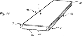
図1のa乃至dは、本発明によるフロアボードの製造を示す。この実施例では、ニードルフェルトでできている層31が、例えば接着剤によってコア30に接合される。このコアは、例えば、パーティクルボード、MDF、HDF、プライッド等のファイバボードでできていてもよい。反りが生じないようにするため、下層、例えばバランシング層32を後側に適用してもよい。この下層は、フォーム、ニードルフェルト、板紙、等の軟質材料であってもよい。これにより、下張り床の凹凸を均し、音響の減少を改善する。この下層は用途によっては必要でない。次いで、厚さが例えば5mm乃至20mmであるのがよいフロアエレメント3を分割し、複数のフロアパネル2にする。次いで、これらのフロアパネルを機械加工し、接合縁部分を形成し、機械式接合システム7、7’を形成する。長側部4a及び4bに設けられたこのような接合システムの一例を図1のdに示す。フロアボードは、幾つかの変形例の方法で製造できる。例えば、表面層31及び/又はバランシング層32を、フロアエレメントのコアでなくフロアパネルのコアに適用してもよい。
1a to 1d show the production of a floorboard according to the invention. In this embodiment, a
図2のa乃至dは、本発明で使用できる機械式接合システムの例を示す。図2のaによる接合システムは、垂直方向スナップ嵌めによって接合できる。図2のb及びcによる接合システムでは、溝36及びタング38が垂直方向接合部D1を形成する。ストリップ6、係止エレメント8、及び係止溝14が水平方向接合部D2を形成する。これらの係止システムは、傾けて水平方向でスナップ嵌めすることによって接合できる。上部接合縁41、42が圧縮可能である場合には、図2のcの接合システムは垂直方向スナップ嵌めによって係止できる。タング32を取り除いた場合、スナップ嵌めを行わずに垂直方向に組み合わせることによって係止を行うことができる。例えばニードルフェルトを含む表面層31を互いに押し付けることができ、これにより垂直方向スナップ嵌めを容易にする。図2のdは、傾け及びスナップ嵌めによって接合できる別の実施例を示す。上部接合縁41、42は、この実施例では、斜面部分を備えている。
2a-2d show examples of mechanical joining systems that can be used in the present invention. The joining system according to FIG. 2a can be joined by a vertical snap fit. In the joining system according to FIGS. 2b and 2c, the
一実施例では、フロアボードは、第1の対の接合縁にこのフロアボードを隣接したフロアボードに垂直方向D1及び水平方向D2の両方向で係止するようになった機械式係止システムを有している。この第1の対の接合縁は、フロアボードの長側部に設けられていてもよい。第2の対の接合縁に、フロアボードを隣接したフロアボードに垂直方向及び/又は水平方向で係止するようになった機械式係止装置を設けていてもよい。この第2の対の接合縁は、フロアボードの短側部に設けられていてもよい。 In one embodiment, the floorboard has a mechanical locking system adapted to lock the floorboard to the adjacent floorboard in both the vertical direction D1 and the horizontal direction D2 at the first pair of joint edges. is doing. The first pair of joining edges may be provided on the long side of the floor board. A mechanical locking device adapted to lock the floor board to the adjacent floor board in the vertical direction and / or the horizontal direction may be provided at the joining edge of the second pair. The second pair of joining edges may be provided on the short side of the floor board.
一実施例では、第2の対の接合縁には、従来技術のさねはぎシステムの場合のように、垂直方向だけでしか係止しない機械式係止装置を設けていてもよい。 In one embodiment, the second pair of mating edges may be provided with a mechanical locking device that locks only in the vertical direction, as is the case with prior art tongue and groove systems.
別の実施例では、第2の対の接合縁に、図2のb又はcの実施例のうちの任意の一方のタング38をなくし、係止ストリップ6の係止エレメント8を係止溝14と係合させたままにした場合のように、水平方向だけでしか係止しない機械式係止装置を設けていてもよい。図2のdでは、このような場合は、タング38又は下リップ39を取り除いた場合に生じる。
In another embodiment, the second pair of joint edges is free of the
図3のa、b、及びcは、この実施例において、MDF又はパーティクルボード等の比較的軟質な材料でできたコア30を持つフロアボードを示す。係止システムは、水平方向長さがコア30の厚さの約半分の係止エレメント8によって、軟質コアに対して調節してある。表面層31は外接合縁40、41を有し、これらの接合縁は、この実施例では、コア30の外部分を越えて突出して突出部を形成する。この突出部は、1mmの数十分の一程度である。表面層の外部分は、敷設と関連して互いに押し付けられ、フロアボードは非常にぴったりと接合される。機械式係止システムは、フロアボードを正確な位置に案内し、高品質の敷設を可能にする。一実施例では、係止システムは、フロアボード1及び1’を互いに押し付けたときに係止エレメント8の係止面9と係止溝14との間に遊びが存在する形状を備えていてもよい。コア31の厚さは、例えば6mm乃至7mmであってもよく、表面層31の厚さは、例えば1mm乃至2mmであってもよい。かくして、この実施例では、フロアボードの全厚は約7mm乃至9mmであってもよく、フロアは、この場合、厚さが約7mm乃至8mmの通常の積層フロアに接合できる。この実施例では、この他の厚さを使用してもよい。
3a, 3b and 3c show in this embodiment a floorboard with a core 30 made of a relatively soft material such as MDF or particleboard. The locking system is adjusted relative to the soft core by a
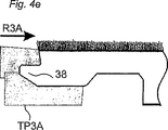
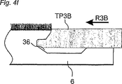
図4のa乃至fは、接合縁部分の機械加工方法を示す。本件出願人は繊維でできた柔らかな表面層は、最も一般的なエレメントである積層体、木製フロア、及び木材を基材としたコア材料の製造で通常使用される切断用回転工具では正確に機械加工できないということを発見した。緩い繊維は、特に隅部で、接合縁をほつれさせてしまう。合成繊維の製造で使用されるプラスチックの融点は、概して、120℃乃至160℃である。繊維は、高い機械加工速度で溶融する。これらの問題点は、表面層を例えばナイフで切断することによって解決できる。これらのナイフTP1A及びTP1Bは回転式であってもよい。これらのナイフの作用角度を図4のa及びbで矢印R1a及びR1bで示す。図示のように90°以外の角度を備えていてもよいナイフがコア30に切り込む。この実施例では、切断部は、完成したフロアのコアの上部分及び外部分の外側に置かれる。図4のc乃至fは、コアの機械加工を行う四つの研削工具TP2A、TP2B、TP3A、及びTP3Aを使用して接合システム全体を形成できるということを示す。図示の実施例の接合システムは、コアと一部品をなして形成される。更に、接合システム全体又はその一部をフロアボードのコアと異なる材料で形成してもよい。例えば、ストリップ6はアルミニウム製であってもよいし、機械加工によってストリップにし、接合縁に機械的に取り付けられたシート状ブランクで形成されていてもよい。
FIGS. 4a to 4f show a method of machining the joint edge portion. The Applicant believes that the soft surface layer made of fibers is accurate in the rotary tools for cutting normally used in the manufacture of the most common elements, laminates, wooden floors, and core materials based on wood. I found that I could not machine. Loose fibers fray joint edges, especially at the corners. The melting point of plastics used in the production of synthetic fibers is generally 120 ° C to 160 ° C. The fiber melts at a high machining speed. These problems can be solved by cutting the surface layer with a knife, for example. These knives TP1A and TP1B may be rotary. The working angles of these knives are indicated by arrows R1a and R1b in FIGS. 4a and 4b. A knife that may have an angle other than 90 ° cuts into the core 30 as shown. In this embodiment, the cuts are placed on the upper part of the core of the finished floor and outside the outer part. FIGS. 4c-f show that the entire joining system can be formed using four grinding tools TP2A, TP2B, TP3A, and TP3A that machine the core. The joining system of the illustrated embodiment is formed in one piece with the core. Further, the entire joining system or a part thereof may be formed of a material different from the floorboard core. For example, the
図5のa乃至cは、二つの表面層を持つフロアボードを示す。フロアボード1、1’は、例えば、積層体又は木材でできた表面層を備えていてもよく、フロアボード2、2’は、例えば、ニードルフェルト、リノリウム、何らかの他の適当な材料でできたプラスチック表面層を備えていてもよい。この他の材料組み合わせを使用してもよい。図5のb及びcは、外上部分への接合を行うことができるということを示す。これらは、本質的には、同じ平面内に位置決めされる。移行ストリップは全く必要とされない。
FIGS. 5a to 5c show a floorboard having two surface layers. The
変形例の設計では、表面層31の繊維は、繊維表面層を持つフロアボードが「通常」のフロアボードよりも僅かに高く見えるように、垂直方向に延びていてもよい。従って、フローリングの所望の表面構造を提供するために、例えば硬質フロアに置かれたラグの外観を提供するため、繊維表面層の垂直方向長さを使用できる。
In an alternative design, the fibers of the
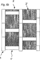
図6のa乃至dは、本発明に従って提供できるフロアの例を説明する。図6のaでは、フロアボード2、2’はニードルフェルト製の表面を有する。これらのフロアボードは、例えば40cm×40cmの正方形である。フロアボード1、1’は、積層体、木材、コルク、リノリウム、プラスチック等でできた表面を有する。例えば、これらのフロアボードは、幅が10cmで長さが40cmであってもよい。図6のbでは、正方形がオフセットしてある。比較的硬質のフロアボード1、1’が軟質のフロアボードよりも幾分下のレベルに位置決めされる場合には、硬質のフロアボードは高い音響レベルを発生しない。これは、これらの硬質のフロアボードが、音響を発生する靴と限られた程度しか接触しないためである。かくして、本発明は、少なくとも二つの異なる表面層がフロアを形成するフロアボードの組に関する。
6a-6d illustrate examples of floors that can be provided in accordance with the present invention. In FIG. 6a, the
図6のc及びdは、色彩、表面構造、等に関して互いに異なる可撓性繊維でできた表面を持つ二つの異なるフロアボードでできたフロアを示す。図6のcでは、フロアボードは、杉綾パターンを形成するように接合されている。これらのフロアボードは、鏡像対称をなして逆になった機械式係止システムを備えている。これにより、傾けること及び/又はスナップ嵌めによって長側部を短側部に接合できる。短側部もまた、傾けること及び/又はスナップ嵌めによって接合できる。図6のcのフロアボードの短側部に水平方向でしか係止しない係止システムが設けられている場合、フロア全体を傾けだけで設置できる。 FIGS. 6 c and d show a floor made of two different floorboards with surfaces made of different flexible fibers with respect to color, surface structure, etc. In FIG. 6c, the floorboards are joined to form a herringbone pattern. These floorboards have a mechanical locking system that is mirror-image-symmetric and reversed. This allows the long side to be joined to the short side by tilting and / or snapping. The short sides can also be joined by tilting and / or snapping. If a locking system that locks only in the horizontal direction is provided on the short side of the floor board in FIG. 6c, the entire floor can be installed simply by tilting.
図7のaは、一方のフロアボード1が、積層体、木材、コルク、リノリウム、プラスチック等からなり、他方のフロアボード2’よりも硬質の表面を持つコンビネーションフロアを示す。一方のフロアボード2’は、この実施例では、他方のフロアボード1’の硬質の表面層よりも高く位置決めされた軟質の表面層を有する。軟質の表面層を硬質の表面層と同じか或いは高いレベルに位置決めするのが好ましい。軟質であり且つ可撓性が高い層により、硬質表面の縁部が保護されるという利点が得られる。
FIG. 7a shows a combination floor in which one
図7のbは、バランシング層として使用されてもよい後側に軟質繊維層32が設けられたフロアボードを示す。
FIG. 7b shows a floorboard provided with a
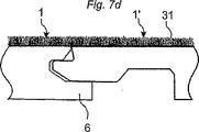
図7のcは、水平方向だけで係止する係止システムを示し、図7のdは、垂直方向だけで係止する係止システムを示す。 FIG. 7c shows a locking system that locks only in the horizontal direction, and FIG. 7d shows a locking system that locks only in the vertical direction.
図7のeは、軟質層31の厚さT1がコアの厚さT2の半分又はそれ以上のフロアボードを示す。このような薄いコアは生産、輸送、等の費用に関して幾つかの利点を提供する。厚さが3mm乃至5mmのシート材料を機械加工することによって機械式係止システムを形成できる。全体に菱形の工具を使用し、最良の価格及び品質レベルを達成するため、工具はできるだけ厚く且つコンパクトでなければならない。製造するのに困難な部分は、溝36である。この実施例では、溝36及びタング38の垂直方向厚さT3は、コア30の厚さT2の半分又はそれ以上である。本発明によるフロアボードによって全ての従来技術の寄木パターン及びタイルパターンを形成できるということは明らかである。フロアボードの側部は垂直である必要がない。軟質表面により異なるフロアボード間で厚さを変えることができる。コアがプラスチックや圧縮積層体等の耐水性材料で形成されている場合には、人工芝に似た繊維表面を持つフロアボードを提供できる。このようなフロアボードは、地面やコンクリートの上に直接敷設でき、例えばゴルフコースのティー、バルコニーフロア、等を形成できる。冬期にはボードを外して屋根の下にしまっておくことができる。
FIG. 7e shows a floor board in which the thickness T1 of the
2 フロアパネル
3 フロアエレメント
4a、4b 長側部
6 ストリップ
7、7’ 機械式接合システム
8 係止エレメント
14 係止溝
30 コア
31 ニードルフェルト層
32 バランシング層
36 溝
38 タング
41、42 上部接合縁
2
Claims (12)
可撓性弾性繊維からなる表面層(31)を木材繊維を含むコア(30)に接合しフロアエレメント(3)を形成する工程と、
フロアエレメント(3)の表面層(31)をフロアエレメントの縁部でナイフ(TP1A,TP1B)により切断する工程と、
ナイフ(TP1A,TP1B)と異なる一組の回転研削工具(TP2A,TP2B,TP3A,TP3B)を準備し、これら一組の回転研削工具に対してフロアエレメントを相対的に直線方向に移動させてフロアエレメントに、連結手段を有する縁部の上方縁部を形成する工程と、
を備え、
ナイフは回転式のナイフ(TP1A,TP1B)からなることを特徴とする方法。A mechanically lockable floorboard (1, 1 ') comprising a surface layer (31) and a core (30) for forming a floating flooring, the floorboards having at least one pair of opposing provided along the edges of, adjacent floorboards and vertically and / or horizontally (respectively, D1, D2) has a connecting means for opposing pairs for engaging each other in a mechanically In a method of manufacturing a floorboard for providing a lockable floating flooring,
Bonding a surface layer (31) made of flexible elastic fibers to a core (30) containing wood fibers to form a floor element (3);
Cutting the surface layer (31) of the floor element (3) with a knife (TP1A, TP1B) at the edge of the floor element;
A set of rotary grinding tools (TP2A, TP2B, TP3A, TP3B) different from the knives (TP1A, TP1B) are prepared, and the floor element is moved in a linear direction relative to the set of rotary grinding tools. Forming an upper edge of an edge having connecting means on the element;
With
A method characterized in that the knife comprises a rotary knife (TP1A, TP1B).
Applications Claiming Priority (3)
| Application Number | Priority Date | Filing Date | Title |
|---|---|---|---|
| SE0300479A SE0300479L (en) | 2003-02-24 | 2003-02-24 | Floorboard and method of manufacture thereof |
| SE0302865A SE526157C2 (en) | 2003-10-29 | 2003-10-29 | Floor board used for floating floors, includes surface layer and core such that surface layer consists of flexible resilient fibers |
| PCT/SE2004/000243 WO2004074597A1 (en) | 2003-02-24 | 2004-02-24 | Floorboard and method of manufacturing thereof |
Publications (2)
| Publication Number | Publication Date |
|---|---|
| JP2006518820A JP2006518820A (en) | 2006-08-17 |
| JP4579231B2 true JP4579231B2 (en) | 2010-11-10 |
Family
ID=32911553
Family Applications (1)
| Application Number | Title | Priority Date | Filing Date |
|---|---|---|---|
| JP2006502812A Expired - Fee Related JP4579231B2 (en) | 2003-02-24 | 2004-02-24 | Floor board and manufacturing method thereof |
Country Status (14)
| Country | Link |
|---|---|
| EP (1) | EP1601844B9 (en) |
| JP (1) | JP4579231B2 (en) |
| KR (1) | KR101206395B1 (en) |
| AT (1) | ATE493551T1 (en) |
| AU (1) | AU2004213740B2 (en) |
| BR (1) | BRPI0407674B1 (en) |
| CA (1) | CA2515402C (en) |
| DE (1) | DE602004030766D1 (en) |
| IL (1) | IL169803A (en) |
| NO (1) | NO338584B1 (en) |
| NZ (1) | NZ542034A (en) |
| PL (1) | PL211011B1 (en) |
| RU (1) | RU2329363C2 (en) |
| WO (1) | WO2004074597A1 (en) |
Families Citing this family (17)
| Publication number | Priority date | Publication date | Assignee | Title |
|---|---|---|---|---|
| SE526333C2 (en) * | 2003-12-11 | 2005-08-23 | Pergo Europ Ab | Flooring system with a plurality of different upper decorative surfaces |
| BE1016216A5 (en) * | 2004-09-24 | 2006-05-02 | Flooring Ind Ltd | FLOOR PANEL AND FLOOR COVERING COMPOSED OF SUCH FLOOR PANELS. |
| CA2618496C (en) * | 2005-08-16 | 2010-02-09 | Johannes Schulte | Method for production of panels |
| DE102005038975B3 (en) | 2005-08-16 | 2006-12-14 | Johannes Schulte | Panel production process for floor, wall or ceiling panels has initial board with parallel grooves in upper and lower surfaces |
| MX2010005489A (en) * | 2007-11-19 | 2010-08-04 | Vaelinge Innovation Belgium Bv | Fibre based panels with a wear resistance surface. |
| KR20100138800A (en) | 2009-06-24 | 2010-12-31 | 동우 화인켐 주식회사 | Detergent composition for solar battery |
| DE102009060103A1 (en) * | 2009-12-21 | 2011-06-22 | Fritz Egger Gmbh & Co. Og | Method for producing a group of panels for imitation of a long plank |
| CN101881076B (en) * | 2010-06-09 | 2014-07-09 | 黄焕文 | Combined floor capable of being paved conveniently |
| WO2013075813A1 (en) * | 2011-11-22 | 2013-05-30 | Hülsta-Werke Hüls Gmbh & Co. Kg | Panel, and method for producing a panel |
| JP5947531B2 (en) * | 2011-12-09 | 2016-07-06 | トヨタホーム株式会社 | Building floor structure and flooring installation method |
| RU2553797C1 (en) * | 2014-04-29 | 2015-06-20 | Федеральное государственное бюджетное образовательное учреждение высшего профессионального образования "Казанский национальный исследовательский технологический университет" (ФГБОУ ВПО "КНИТУ") | Batten |
| DE102015005864A1 (en) * | 2015-05-11 | 2016-11-17 | Fritz Egger Gmbh & Co. Og | Process for the production of wells having panels |
| JP2019007266A (en) * | 2017-06-27 | 2019-01-17 | パナソニックIpマネジメント株式会社 | Floor member |
| LU101424B1 (en) * | 2019-10-08 | 2021-04-09 | Tarkett Gdl Sa | Set of tiles to cover a support surface, and associated cover element and method |
| BE1027634B1 (en) | 2019-10-08 | 2021-05-06 | Flooring Ind Ltd Sarl | Floor panel for forming a floor covering |
| DE102020127485A1 (en) | 2020-10-19 | 2022-04-21 | Guido Schulte | Process for the production of panel-shaped components |
| DE102020127487A1 (en) | 2020-10-19 | 2022-04-21 | Guido Schulte | Panel-shaped components |
Family Cites Families (22)
| Publication number | Priority date | Publication date | Assignee | Title |
|---|---|---|---|---|
| SE414067B (en) * | 1977-03-30 | 1980-07-07 | Wicanders Korkfabriker Ab | DISCOVERED FLOOR ELEMENT WITH NOTE AND SPONGE FIT |
| JPS56104936U (en) * | 1980-01-16 | 1981-08-15 | ||
| JPS56131752A (en) * | 1980-03-15 | 1981-10-15 | Matsushita Electric Works Ltd | Panel carpet |
| JPS57157636U (en) * | 1981-03-30 | 1982-10-04 | ||
| US4489115A (en) * | 1983-02-16 | 1984-12-18 | Superturf, Inc. | Synthetic turf seam system |
| JPH07102532B2 (en) * | 1989-01-17 | 1995-11-08 | 朝日ウッドテック株式会社 | Manufacturing method of grooved decorative board |
| DE4020682A1 (en) * | 1989-01-20 | 1992-01-02 | Darma Joseph | Constructional of raw material for parquet floors - comprises bamboo canes peeled into thin strips and flat pressed into alternate layers with a binder |
| ES2027118A6 (en) * | 1990-10-17 | 1992-05-16 | Pedros Batlle Agustin | Variable geometry protector device for wood forming machines. |
| JP2676297B2 (en) * | 1992-05-15 | 1997-11-12 | 住江織物株式会社 | Tile carpet with good shape stability and method for producing the same |
| SE9301595L (en) | 1993-05-10 | 1994-10-17 | Tony Pervan | Grout for thin liquid hard floors |
| BE1010487A6 (en) | 1996-06-11 | 1998-10-06 | Unilin Beheer Bv | FLOOR COATING CONSISTING OF HARD FLOOR PANELS AND METHOD FOR MANUFACTURING SUCH FLOOR PANELS. |
| JPH102096A (en) * | 1996-06-19 | 1998-01-06 | Matsushita Electric Works Ltd | Floor material and manufacture of floor material |
| JPH11268010A (en) * | 1998-03-20 | 1999-10-05 | Fuji Seisakusho:Kk | Log cutting device |
| SE512313E (en) | 1998-06-03 | 2000-02-28 | Valinge Aluminium Ab | Locking system and floorboard |
| SE512290C2 (en) | 1998-06-03 | 2000-02-28 | Valinge Aluminium Ab | Locking system for mechanical joining of floorboards and floorboard provided with the locking system |
| SE517478C2 (en) * | 1999-04-30 | 2002-06-11 | Valinge Aluminium Ab | Locking system for mechanical hoisting of floorboards, floorboard provided with the locking system and method for producing mechanically foldable floorboards |
| FR2810060A1 (en) | 2000-06-08 | 2001-12-14 | Ykk France | Wooden floor paneling, for parquet floor, has elastic strip with lateral flanges forming stop faces for recessed surfaces on panels |
| JP2002011708A (en) * | 2000-06-28 | 2002-01-15 | Juken Sangyo Co Ltd | Surface-reinforced building material |
| IL156528A0 (en) | 2001-01-12 | 2004-01-04 | Valinge Aluminium Ab | Floorboard and locking system |
| BE1014345A3 (en) * | 2001-08-14 | 2003-09-02 | Unilin Beheer Bv | Floor panel and method for manufacturing it. |
| BRPI0308966B8 (en) | 2002-04-03 | 2016-05-17 | Vaelinge Innovation Ab | floor board |
| BR0309248B1 (en) * | 2002-04-22 | 2013-04-02 | floor comprising rectangular floorboards with a laminate surface to provide a standard floating floor. |
-
2004
- 2004-02-24 JP JP2006502812A patent/JP4579231B2/en not_active Expired - Fee Related
- 2004-02-24 DE DE602004030766T patent/DE602004030766D1/en not_active Expired - Lifetime
- 2004-02-24 NZ NZ542034A patent/NZ542034A/en not_active IP Right Cessation
- 2004-02-24 BR BRPI0407674-5A patent/BRPI0407674B1/en not_active IP Right Cessation
- 2004-02-24 AU AU2004213740A patent/AU2004213740B2/en not_active Ceased
- 2004-02-24 RU RU2005129735/03A patent/RU2329363C2/en not_active IP Right Cessation
- 2004-02-24 AT AT04714059T patent/ATE493551T1/en not_active IP Right Cessation
- 2004-02-24 KR KR1020057015580A patent/KR101206395B1/en active IP Right Grant
- 2004-02-24 CA CA2515402A patent/CA2515402C/en not_active Expired - Fee Related
- 2004-02-24 PL PL376863A patent/PL211011B1/en unknown
- 2004-02-24 EP EP04714059A patent/EP1601844B9/en not_active Expired - Lifetime
- 2004-02-24 WO PCT/SE2004/000243 patent/WO2004074597A1/en active Application Filing
-
2005
- 2005-07-21 IL IL169803A patent/IL169803A/en active IP Right Grant
- 2005-07-28 NO NO20053665A patent/NO338584B1/en not_active IP Right Cessation
Also Published As
| Publication number | Publication date |
|---|---|
| AU2004213740B2 (en) | 2010-01-21 |
| NZ542034A (en) | 2007-04-27 |
| BRPI0407674A (en) | 2006-03-01 |
| NO20053665L (en) | 2005-09-22 |
| BRPI0407674B1 (en) | 2015-01-06 |
| NO20053665D0 (en) | 2005-07-28 |
| EP1601844B1 (en) | 2010-12-29 |
| IL169803A (en) | 2008-11-03 |
| AU2004213740A1 (en) | 2004-09-02 |
| JP2006518820A (en) | 2006-08-17 |
| NO338584B1 (en) | 2016-09-12 |
| KR101206395B1 (en) | 2012-11-29 |
| RU2329363C2 (en) | 2008-07-20 |
| PL376863A1 (en) | 2006-01-09 |
| ATE493551T1 (en) | 2011-01-15 |
| PL211011B1 (en) | 2012-03-30 |
| EP1601844A1 (en) | 2005-12-07 |
| KR20050103953A (en) | 2005-11-01 |
| WO2004074597A1 (en) | 2004-09-02 |
| CA2515402C (en) | 2012-09-25 |
| DE602004030766D1 (en) | 2011-02-10 |
| EP1601844B9 (en) | 2012-01-25 |
| RU2005129735A (en) | 2006-04-10 |
| CA2515402A1 (en) | 2004-09-02 |
Similar Documents
| Publication | Publication Date | Title |
|---|---|---|
| US10137659B2 (en) | Floorboard and method for manufacturing thereof | |
| US11066836B2 (en) | Floorboards comprising a decorative edge part in a resilient surface layer | |
| JP4579231B2 (en) | Floor board and manufacturing method thereof | |
| JP4652339B2 (en) | Floorboard, flooring forming system and method, and flooring formed thereby | |
| ZA200505871B (en) | Floorboard and method of manufacturing thereof |
Legal Events
| Date | Code | Title | Description |
|---|---|---|---|
| A621 | Written request for application examination |
Free format text: JAPANESE INTERMEDIATE CODE: A621 Effective date: 20070125 |
|
| A131 | Notification of reasons for refusal |
Free format text: JAPANESE INTERMEDIATE CODE: A131 Effective date: 20091113 |
|
| A521 | Request for written amendment filed |
Free format text: JAPANESE INTERMEDIATE CODE: A523 Effective date: 20100212 |
|
| A131 | Notification of reasons for refusal |
Free format text: JAPANESE INTERMEDIATE CODE: A131 Effective date: 20100409 |
|
| A521 | Request for written amendment filed |
Free format text: JAPANESE INTERMEDIATE CODE: A523 Effective date: 20100707 |
|
| TRDD | Decision of grant or rejection written | ||
| A01 | Written decision to grant a patent or to grant a registration (utility model) |
Free format text: JAPANESE INTERMEDIATE CODE: A01 Effective date: 20100730 |
|
| A01 | Written decision to grant a patent or to grant a registration (utility model) |
Free format text: JAPANESE INTERMEDIATE CODE: A01 |
|
| A61 | First payment of annual fees (during grant procedure) |
Free format text: JAPANESE INTERMEDIATE CODE: A61 Effective date: 20100825 |
|
| FPAY | Renewal fee payment (event date is renewal date of database) |
Free format text: PAYMENT UNTIL: 20130903 Year of fee payment: 3 |
|
| R150 | Certificate of patent or registration of utility model |
Ref document number: 4579231 Country of ref document: JP Free format text: JAPANESE INTERMEDIATE CODE: R150 Free format text: JAPANESE INTERMEDIATE CODE: R150 |
|
| R250 | Receipt of annual fees |
Free format text: JAPANESE INTERMEDIATE CODE: R250 |
|
| R250 | Receipt of annual fees |
Free format text: JAPANESE INTERMEDIATE CODE: R250 |
|
| R250 | Receipt of annual fees |
Free format text: JAPANESE INTERMEDIATE CODE: R250 |
|
| R250 | Receipt of annual fees |
Free format text: JAPANESE INTERMEDIATE CODE: R250 |
|
| R250 | Receipt of annual fees |
Free format text: JAPANESE INTERMEDIATE CODE: R250 |
|
| R250 | Receipt of annual fees |
Free format text: JAPANESE INTERMEDIATE CODE: R250 |
|
| R250 | Receipt of annual fees |
Free format text: JAPANESE INTERMEDIATE CODE: R250 |
|
| LAPS | Cancellation because of no payment of annual fees |