JP4570822B2 - Horizontal pump gate for low suction water level - Google Patents
Horizontal pump gate for low suction water level Download PDFInfo
- Publication number
- JP4570822B2 JP4570822B2 JP2001246568A JP2001246568A JP4570822B2 JP 4570822 B2 JP4570822 B2 JP 4570822B2 JP 2001246568 A JP2001246568 A JP 2001246568A JP 2001246568 A JP2001246568 A JP 2001246568A JP 4570822 B2 JP4570822 B2 JP 4570822B2
- Authority
- JP
- Japan
- Prior art keywords
- pump
- gate
- hood
- water
- fluid
- Prior art date
- Legal status (The legal status is an assumption and is not a legal conclusion. Google has not performed a legal analysis and makes no representation as to the accuracy of the status listed.)
- Expired - Lifetime
Links
Images
Landscapes
- Barrages (AREA)
- Structures Of Non-Positive Displacement Pumps (AREA)
Description
【0001】
【発明の属する技術分野】
本発明は、流体が流れる流体路に設置されたゲートにポンプを取り付けたポンプゲートに関するものである。
【0002】
【従来の技術】
従来より、河川や水路(流体路)の途中にポンプを内蔵したゲートを設置し、このゲートによって仕切られた一方の側(吸込側)からポンプによって水(流体)を吸い込み、他方の側(吐出側)へ水を吐出するポンプゲートが知られている。このポンプゲートとしては、ポンプの吸込口を水路の水底側に向けた縦型ポンプゲートがある。縦型ポンプゲートは、水路中の流れを水路の水底側から真上に吸い上げるので、流向の変化が激しく、流速分布が不均一になりやすい。また、吸込口と水底との距離が近いので吸込口周辺の流速が早くなりやすい。したがって、水位が低くなったとき、水面で空気吸い込み渦を発生しやすくなる。すると、ポンプ自体が振動してポンプ性能が低下し、低水位まで水を安定して吸い込めなくなる。
【0003】
そこで、近年では、ポンプの吸込口を水路の水面と平行になるように設置した横型ポンプゲートが用いられるようになっている。この横型ポンプゲートは、水路の流れをそのままポンプ内に取り込むので、流れの向きが安定し、流速分布が均一となり、縦型ポンプゲートに比べて低水位まで水を吸い込むことができる。
【0004】
【発明が解決しようとする課題】
しかしながら、上述したような横型ポンプゲートにおいても、水位が更に低くなると水面から空気を吸い込んでしまい、ポンプ性能が低下して低水位まで水を吸い込めなくなる。この場合、ポンプ設置位置近傍の水路を掘り下げることによってポンプの吸い込み可能な水位を低くすることが考えられるが、そのための作業が必要となってしまうとともに、掘り下げたところに汚泥等が堆積し、異臭を発生するといった問題が生じる。また、ポンプの回転数を下げて吸い込む水の流速を遅くすることにより、水面からの空気の吸い込みを抑える方法も考えられるが、単位時間当たりの吸い込み量が低下するとともに、ポンプに回転数制御系を備える必要があり、装置の大型化やコスト上昇を招く。
【0005】
本発明は、このような事情に鑑みてなされたものであって、流体を低位置まで容易に安定して吸い込むことができるポンプを備えたポンプゲートを提供することを目的とする。
【0006】
【課題を解決するための手段】
上記の課題を解決するため、本発明のポンプゲートは、流体が流れる流体路に設置されるゲートと、該ゲートに取り付けられ、前記流体路のうち前記ゲートによって仕切られた一方の側から流体を吸い込んで、他方の側に前記流体を吐出するポンプとを備えたポンプゲートにおいて、前記ポンプのうち前記流体を吸い込むための吸込口が、前記流体路を流れる流体の表面に対して前記一方の側に向かって斜め下向きになるように、前記ゲートに対して前記ポンプが取り付けられていることを特徴とする。
【0007】
本発明によれば、ポンプの吸込口を流体路を流れる流体の表面に対して斜め下向きにすることにより、この吸込口を低位置に配置することができるので、流体路を掘り下げることなく、流体を低位置まで安定して吸い込むことができる。また、吸込口が流体の流入方向に対して下向きに傾斜して配置されることになるので、吸込口の真上にある流体を吸い込む流れを減速させることになり、空気吸い込み渦の発生を抑えることができる。したがって、流体の表面側から空気を吸い込まずに、流体を低位置まで安定して吸い込むことができる。
【0008】
前記ポンプの吸込口にはフードが設けられているので、ポンプの吸込口に多くの流体を取り込めることができるとともに、流入する流体を整流することができる。
【0009】
前記フードの開口部は、上部側(前記流体路を流れる流体の表面側)を大きく、下部側(前記流体路の底側)に向かって徐々に開口を小さく形成されているので、フードの入口における上部側部分(流体の表面側部分)の流速を小さく、下部側部分(流体の底側部分)の流速を大きくできる。したがって、流体路の表面側で発生する空気吸い込み渦の発生をさらに抑えることができる。
【0010】
前記フードの下部には、前記一方の側に向かって突起した突起部が設けられているので、フードの下部側からフードに対して回り込む流れを抑えることができる。したがって、この回り込む流れに起因する渦の発生を抑えることができる。
【0011】
前記フードの開口部の上部側にはリブ状部材が設けられているので、このリブ状部材が流れの抵抗となり、フードの入口における上部側部分の流速を小さくすることができる。したがって、流体路の表面側で発生する空気吸い込み渦の発生をさらに抑えることができる。
【0012】
【発明の実施の形態】
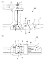
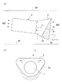
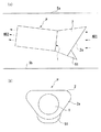
以下、本発明のポンプゲートについて図面を参照しながら説明する。図1は本発明のポンプゲートの一実施形態を示す図であって、図1(a)は側面図、図1(b)は平面図である。また、図2はポンプの拡大図であって、図2(a)は側面図、図2(b)は吸込側から見た正面図である。
【0013】
図1に示すように、ポンプゲートPGは、水路(流体路)Sに設置されたゲートGと、このゲートGに取り付けられたポンプPとを備えている。ポンプゲートPGはゲートGによって水路Sを仕切るようになっており、ポンプPの駆動によって、ゲートGに仕切られた一方の側である吸込側AR1から水(流体)を吸い込んで、他方の側である吐出側AR2に水を吐出するものである。このポンプゲートPGが設置される場所としては、例えば、用水路の途中や堤防の手前、あるいは河川の川表などがある。
【0014】
水が吸い込まれる側である吸込側AR1の水路Sにはスクリーン10が設けられている。このスクリーン10は巻上機11によって水路Sに対して開閉可能に設けられている。スクリーン10を通過した水はポンプP側に流れる。また、水路Sの吸込側AR1の上部には橋12が設置されている。管理橋13の一部にはゲートGを開閉する開閉機14が設けられている。
【0015】
ポンプPは、図1(b)に示すように、水路S中に、水平方向に並列に2つ設けられている。ポンプPの設置数としては、水路Sの大きさに応じて任意の複数あるいは1つ設けられる。
【0016】
図2に示すように、ポンプPは、水路Sのうち吸込側AR1の水を吸い込むための吸込口1を有している。このとき、ポンプPは、このポンプPの吸込口1が水路Sを流れる水の表面(水面)Saに対して、水路Sの吸込側(一方の側)AR1に向かって斜め下向きになるように設置されている。すなわち、ポンプPの吸込口1は、水の流入方向に対して、水底Sb側に傾斜するように設定されている。この場合、吸込口1の傾斜角度θ1 は、水面Saに対して(水の流入方向に対して)、5〜30°に設定されている。
【0017】
ポンプPの吸込口1にはフード2が取り付けられている。このフード2は、図2(b)に示すように、上部側(水面Sa側)の開口が大きく、下部側(水底Sb側)に向かって徐々に開口が小さくなるように形成されている。このフード2の上側部分の形状は、水面Saと平行もしくは吸込側AR1に向かって若干下向きになるように設けられている。また、フード2の上側部分は、流入方向と交わる水平方向(矢印y参照)に拡がるように形成されることによって、その開口を大きくしている。なお、流速を損失させないように、フード2は曲線状に形成されている。
【0018】
なお、本実施形態においては、フード2は、図2(a)の側面図に示すように、上側部分の流入方向におけるサイズを下側部分より長く形成され、フード2の入口2aを水底Sb側に更に向くように設定されている。すなわち、フード2の入口2aの水面Saに対する傾斜角度θ2 は、吸込口1の水面Saに対する傾斜角度θ1 より大きく設定されているが、図2の斜線部分に示すように、フード2の上側部分の流入方向におけるサイズを下側部分と等しく形成してもよい。すなわち、フード2の入口2aの水面Saに対する傾斜角度θ2 と、吸込口1の水面Saに対する傾斜角度θ1 とが同じになるように設定してもよい。
【0019】
以上説明したような構成を有するポンプゲートPGによって、吸込側AR1の水を吸い込んで、吐出側AR2に吐出する際の動作について説明する。
図1に示すように、水路Sのうち、吸込側AR1の水が、スクリーン10を介してポンプゲートPGのポンプPに流入する。ポンプPは、吸込側AR1に向かって水底Sb側に傾斜した吸込口1から水を吸い込む。
【0020】
ポンプPが水を吸い込むことにより、水路Sの吸込側AR1の水位は徐々に低下する。このとき、吸込口1が水底Sb側に傾斜しているため、ポンプゲートPGのポンプPは、低水位まで水を安定して吸い込むことができる。
【0021】
吸込口1には、上部側(水面Sa側)の開口が大きく、下部側(水底Sb側)に向かって徐々に開口が小さくなるように形成されたフード2が取り付けられており、このフード2によって、流路が拡大されたフード2の上部側(水面Sa側)部分の入口において、水の流速は低下する。水面Sa側の水の流速が低下することにより、フード2の入口における水面Sa側には空気吸い込み渦が発生しにくくなる。そして、このフード2の上側部分を、図2(a)に示すように水面Saに対して平行もしくは水路Sの吸込側AR1に向かって若干下向きに形成したことにより、水を低水位まで吸い込むことができる。ポンプPの吸込口1から吸い込まれた吸込側AR1の水は、ポンプゲートPGを通過して、吐出側AR2に吐出される。
【0022】
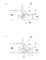
ここで、図3を用いて、本発明のポンプゲートPGのポンプPが従来より低水位まで水を吸い込める理由について説明する。
図3(a)は従来のポンプゲートであって、ポンプPの吸込口1は真横に向けられている。一方、図3(b)は本発明のポンプゲートであって、ポンプPの吸込口1は吸込側AR1に向かって下方に傾斜されている。図3(a)に示す従来のポンプゲートでは、吸い込み可能な最低水位h1を確保するために、例えば水路を掘り下げて、ポンプPを深い位置に設置しなければならない。
【0023】
しかしながら、図3(b)に示す本発明のポンプゲートPGにおいては、ポンプPの吸込口1は水底Sb側に向けられているので、水路Sを掘り下げることなく、ポンプPによって吸い込み可能な最低水位h1を低くすることができる。このように、吸込口1を斜め下方に向けることにより、吸込口1を水面Saに対して深い位置に配置することができるので、空気吸い込み渦を発生することなく、低水位まで水を吸い込むことができる。
【0024】
さらに、吸込口1を水の流入方向に対して斜め下向きに設けたことにより、図3(b)に示すように、水面Saよりも水底Sbに近い側の流体を吸い込む力を強くする。このため、流速方向はm1 からm2 へと変化し、水面Saからの流れ込みが減少し、空気吸い込み渦の発生を抑えることができる。したがって、表面Sa側から空気を吸い込まずに、水を低水位まで安定して吸い込むことができる。
【0025】
また、従来のポンプゲートにおいても吸込口1にフード2が設けられているが、図3(a)に示すように、上下対称な形状を有しており、水位が下がると水面Sa側から空気を吸い込んでしまう。しかしながら、本発明のポンプゲートPGのポンプPに取り付けられたフード2は、その上側(水面Sa側)部分が水面Saに対して平行もしくは吸込側AR1に向かって下向きになるように形成されているとともに、このフード2の上部側部分は、図2の矢印y方向に拡がるように形成されることによって開口を大きくし、流速を低下させている。したがって、従来例に比べて低い水位になっても、水面Saから空気を吸い込むことなく吸込側AR1の水を安定して吸い込むことができる。つまり、従来例に比べて、本発明のフード2を備えたポンプPは、吸込側AR1の水面SaとポンプPの吸込口1との距離h2を維持したまま、吸い込み可能な最低水位h1を低くすることができる。
【0026】
以上説明したように、ポンプPの吸込口1を、水路Sの水の水面Saに対して水路Sの吸込側AR1に向かって斜め下向きにしたことにより、水路Sを掘り下げることなく、表面Sa側から空気を吸い込まずに、低水位まで水を安定して吸い込むことができる。
【0027】
そして、ポンプPの吸込口1に、上側(水面Sa側)部分の開口が大きく、下側(水底Sb側)に向かって徐々に開口が小さくなるように形成されたフード2を設けたことにより、吸込口1に多くの水を取り込めることができるとともに、フード2の入口において、水面Sa側の水の流速を小さく、水底Sb側の流速を大きくできる。したがって、表面Saにおいて空気吸い込み渦の発生を抑えつつ、低水位まで水を吸い込むことができる。さらに、フード2の上側部分を水面Saに対して平行もしくは下向きになるように、且つ矢印y方向に拡げてこのフード2の上側部分の開口を大きくしたことにより、水面Saと吸込口1との距離h2を維持したまま、水面Saから空気を吸い込まずに水を吸い込み可能な最低水位h1を小さくすることができる。
【0028】
本実施形態においては、フード2の入口2aにおける上部側の開口を、図2(b)に示したように大きくすることによって、フード2の上部側の流速を下部側より低下させているが、図4に示すような形態にすることも可能である。図4(a)はフード2を備えたポンプPを示す側面図であり、図4(b)は吸込口側から見た正面図である。図4(b)に示すように、フード2の開口の下部側には、このフード2の下部側の流路を狭めるためのブロック41が設けられている。このように、フード2の開口の下部側にブロック41を設けることによっても、フード2の上部側の流速を下部側より低下させることができる。ここで、図4(a)に示すように、フード2の側面視上側部分と下側部分とは同じサイズを有している(すなわち、吸込口1の水面Saに対する傾斜角度θ1 とフード2の入口2aの水面Saに対する傾斜角度θ2 とが同じに設定されている)が、図2に示した実施形態と同様、フード2の側面視上側部分と下側部分とのサイズをそれぞれ異ならせてもよい。また、フード2の上側部分を、流入方向と交わる水平方向(図2(b)の矢印y参照)に拡がるように形成して、その開口の上部側部分を大きくしてもよい。
【0029】
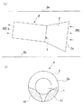
図5に示すように、フード2の下部に、吸込側AR1に向かって突起した突起部51を設けてもよい。この突起部51によって、フード2の下部側からフードに対して回り込む流れを抑えることができる。したがって、この回り込む流れに起因する渦の発生を抑えることができ、ポンプPは安定した吸い込み動作を行うことができる。
【0030】
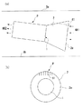
図6に示すように、フード2の開口の上部側にリブ状部材61を設けてもよい。このリブ状部材61は、フード2の開口の上部側(水面Sa側)に流入方向に沿うように複数設けられている。フード2の開口の上部側にリブ状部材61を設けたことにより、このリブ状部材61が流れの抵抗となって、フード2の入口2aにおける上部側部分の流速を低下させることができる。したがって、流体路の水面Sa側で発生する空気吸い込み渦の発生をさらに抑えることができる。
【0031】
【発明の効果】
本発明のポンプゲートは以下のような効果を有するものである。
請求項1に記載の発明は、ポンプのうち流体を吸い込むための吸込口が、流体路を流れる流体の表面に対して斜め下向きになるように設定されている構成となっている。
こうすることにより、この吸込口を低位置に配置することができるので、流体路を掘り下げることなく、流体を低位置まで安定して吸い込むことができる。また、吸込口が流体の流入方向に対して下向きに傾斜して配置されることになるので、吸込口に流入する流体の流速は流入方向に比べて減速されるが、流体の流速が減速することにより、空気吸い込み渦の発生を抑えることができる。したがって、流体の表面側から空気を吸い込まずに、流体を低位置まで安定して吸い込むことができる。
【0032】
請求項2に記載の発明は、ポンプの吸込口にはフードが設けられている構成となっている。
こうすることにより、ポンプの吸込口に多くの流体を取り込めることができるとともに、流入する流体を整流することができる。
【0033】
請求項3に記載の発明は、フードの開口部は、上部側を大きく、下部側に向かって徐々に開口を小さく形成されている構成となっている。
こうすることにより、フードの入口における上部側部分の流速を小さく、下部側部分の流速を大きくできる。したがって、流体路の表面側で発生する空気吸い込み渦の発生をさらに抑えることができる。
【0034】
請求項4に記載の発明は、フードの下部には、一方の側に向かって突起した突起部が設けられている構成となっている。
こうすることにより、フードの下部側からフードに対して回り込む流れを抑えることができる。したがって、この回り込む流れに起因する渦の発生を抑えることができる。
【0035】
請求項5に記載の発明は、フードの開口部の上部側にはリブ状部材が設けられている構成となっている。
こうすることにより、このリブ状部材が流れの抵抗となり、フードの入口における上部側部分の流速を小さくすることができる。したがって、流体路の表面側で発生する空気吸い込み渦の発生をさらに抑えることができる。
【図面の簡単な説明】
【図1】本発明のポンプゲートの一実施形態を示す構成図であって、図1(a)は側面図であり、図1(b)は平面図である。
【図2】ポンプの拡大図であって、図2(a)は側面図であり、図2(b)は吸込側から見た正面図である。
【図3】従来のポンプゲートと本発明に係るポンプゲートとを比較する図である。
【図4】ポンプに設けられたフードの他の実施形態を示す図であって、図4(a)は側面図であり、図4(b)は吸込側から見た正面図である。
【図5】ポンプに設けられたフードの他の実施形態を示す図であって、図5(a)は側面図であり、図5(b)は吸込側から見た正面図である。
【図6】ポンプに設けられたフードの他の実施形態を示す図であって、図6(a)は側面図であり、図6(b)は吸込側から見た正面図である。
【符号の説明】
1 吸込口
2 ゲート
51 突起部
61 リブ状部材
AR1 吸込側(一方の側)
AR2 吐出側(他方の側)
G ゲート
P ポンプ
PG ポンプゲート
S 水路(流体路)
Sa 水面(表面)
Sb 水底[0001]
BACKGROUND OF THE INVENTION
The present invention relates to a pump gate in which a pump is attached to a gate installed in a fluid path through which a fluid flows.
[0002]
[Prior art]
Conventionally, a gate with a built-in pump is installed in the middle of a river or water channel (fluid channel), and water (fluid) is sucked by the pump from one side (suction side) partitioned by this gate, and the other side (discharge) A pump gate that discharges water to the side) is known. As this pump gate, there is a vertical pump gate in which the suction port of the pump faces the bottom of the water channel. The vertical pump gate sucks the flow in the water channel right above the bottom of the water channel, so that the flow direction changes drastically and the flow velocity distribution tends to be uneven. Moreover, since the distance between the suction port and the bottom of the water is close, the flow velocity around the suction port tends to increase. Therefore, when the water level becomes low, air suction vortices are likely to be generated on the water surface. Then, the pump itself vibrates and the pump performance deteriorates, and water cannot be sucked stably to a low water level.
[0003]
Therefore, in recent years, a horizontal pump gate in which the suction port of the pump is installed so as to be parallel to the water surface of the water channel has been used. Since this horizontal pump gate takes the flow of the water channel into the pump as it is, the flow direction is stabilized, the flow velocity distribution is uniform, and water can be sucked to a lower water level than the vertical pump gate.
[0004]
[Problems to be solved by the invention]
However, even in the horizontal pump gate as described above, if the water level is further lowered, air is sucked from the water surface, the pump performance is lowered, and water cannot be sucked to the low water level. In this case, it is conceivable to lower the water level that can be sucked into the pump by digging down the water channel near the pump installation position, but this requires work, and sludge accumulates at the digging site, causing off-flavors. The problem of generating In addition, it is possible to suppress the suction of air from the water surface by lowering the flow rate of the sucked water by lowering the pump speed, but the suction amount per unit time is reduced and the pump has a speed control system. This increases the size and cost of the apparatus.
[0005]
This invention is made | formed in view of such a situation, Comprising: It aims at providing the pump gate provided with the pump which can suck | inhale the fluid easily to a low position stably.
[0006]
[Means for Solving the Problems]
In order to solve the above problems, a pump gate of the present invention includes a gate installed in a fluid path through which a fluid flows, and a fluid that is attached to the gate and separated from one side of the fluid path that is partitioned by the gate. A pump gate including a pump that sucks and discharges the fluid on the other side, wherein a suction port for sucking the fluid of the pump is on the one side with respect to a surface of the fluid flowing in the fluid path The pump is attached to the gate so as to be inclined obliquely downward.
[0007]
According to the present invention, since the suction port of the pump is inclined downward with respect to the surface of the fluid flowing through the fluid path, the suction port can be disposed at a low position, so that the fluid can be obtained without digging down the fluid path. Can be stably sucked up to a low position. In addition, since the suction port is arranged to be inclined downward with respect to the fluid inflow direction, the flow of sucking the fluid immediately above the suction port is decelerated, and the generation of the air suction vortex is suppressed. be able to. Therefore, the fluid can be stably sucked to a low position without sucking air from the surface side of the fluid.
[0008]
Since the hood is provided at the suction port of the pump, a large amount of fluid can be taken into the suction port of the pump and the inflowing fluid can be rectified.
[0009]
The opening of the hood is formed such that the upper side (the surface side of the fluid flowing through the fluid path) is large and the opening is gradually reduced toward the lower side (bottom side of the fluid path). The flow rate of the upper part (the surface side part of the fluid) can be reduced and the flow rate of the lower part (the bottom part of the fluid) can be increased. Therefore, it is possible to further suppress the generation of air suction vortices generated on the surface side of the fluid path.
[0010]
Since the protrusion part which protruded toward the said one side is provided in the lower part of the said hood, the flow which goes around with respect to a hood from the lower part side of a hood can be suppressed. Therefore, it is possible to suppress the generation of vortices caused by the flowing flow.
[0011]
Since a rib-like member is provided on the upper side of the opening portion of the hood, the rib-like member serves as a flow resistance, and the flow rate of the upper side portion at the inlet of the hood can be reduced. Therefore, it is possible to further suppress the generation of air suction vortices generated on the surface side of the fluid path.
[0012]
DETAILED DESCRIPTION OF THE INVENTION
Hereinafter, the pump gate of the present invention will be described with reference to the drawings. FIG. 1 is a view showing an embodiment of a pump gate according to the present invention. FIG. 1 (a) is a side view and FIG. 1 (b) is a plan view. 2 is an enlarged view of the pump, FIG. 2 (a) is a side view, and FIG. 2 (b) is a front view as seen from the suction side.
[0013]
As shown in FIG. 1, the pump gate PG includes a gate G installed in a water channel (fluid channel) S and a pump P attached to the gate G. The pump gate PG partitions the water channel S by the gate G. When the pump P is driven, water (fluid) is sucked from the suction side AR1 which is one side partitioned by the gate G, and the other side. Water is discharged to a certain discharge side AR2. As a place where this pump gate PG is installed, there is, for example, in the middle of a irrigation channel, before a dike, or a river surface of a river.
[0014]
A
[0015]
As shown in FIG. 1B, two pumps P are provided in the water channel S in parallel in the horizontal direction. Depending on the size of the water channel S, any number or one of the pumps P may be installed.
[0016]
As shown in FIG. 2, the pump P has a
[0017]
A
[0018]
In this embodiment, as shown in the side view of FIG. 2A, the
[0019]
An operation when the water on the suction side AR1 is sucked and discharged to the discharge side AR2 by the pump gate PG having the above-described configuration will be described.
As shown in FIG. 1, the water on the suction side AR <b> 1 in the water channel S flows into the pump P of the pump gate PG via the
[0020]
As the pump P sucks water, the water level on the suction side AR1 of the water channel S gradually decreases. At this time, since the
[0021]
A
[0022]
Here, the reason why the pump P of the pump gate PG of the present invention can suck water to a lower water level than before will be described with reference to FIG.
FIG. 3A is a conventional pump gate, and the
[0023]
However, in the pump gate PG of the present invention shown in FIG. 3B, since the
[0024]
Further, by providing the
[0025]
Also, in the conventional pump gate, the
[0026]
As described above, the
[0027]
And by providing the
[0028]
In the present embodiment, the flow rate on the upper side of the
[0029]
As shown in FIG. 5, a
[0030]
As shown in FIG. 6, a rib-
[0031]
【The invention's effect】
The pump gate of the present invention has the following effects.
The invention according to
By doing so, the suction port can be arranged at a low position, so that the fluid can be stably sucked to the low position without digging down the fluid path. Further, since the suction port is arranged to be inclined downward with respect to the fluid inflow direction, the flow velocity of the fluid flowing into the suction port is decelerated compared to the inflow direction, but the fluid flow velocity is decelerated. Thus, the generation of air suction vortex can be suppressed. Therefore, the fluid can be stably sucked to a low position without sucking air from the surface side of the fluid.
[0032]
The invention according to
By doing so, a large amount of fluid can be taken into the suction port of the pump and the inflowing fluid can be rectified.
[0033]
The invention according to claim 3 is configured such that the opening of the hood is formed such that the upper side is larger and the opening is gradually smaller toward the lower side.
By doing so, it is possible to reduce the flow velocity of the upper portion at the entrance of the hood and increase the flow velocity of the lower portion. Therefore, it is possible to further suppress the generation of air suction vortices generated on the surface side of the fluid path.
[0034]
The invention according to claim 4 has a configuration in which a protruding portion protruding toward one side is provided at the lower portion of the hood.
By doing so, the flow around the hood from the lower side of the hood can be suppressed. Therefore, it is possible to suppress the generation of vortices caused by the flowing flow.
[0035]
The invention according to claim 5 is configured such that a rib-like member is provided on the upper side of the opening of the hood.
By doing so, the rib-shaped member becomes a flow resistance, and the flow velocity of the upper side portion at the entrance of the hood can be reduced. Therefore, it is possible to further suppress the generation of air suction vortices generated on the surface side of the fluid path.
[Brief description of the drawings]
FIG. 1 is a configuration diagram showing an embodiment of a pump gate according to the present invention, in which FIG. 1 (a) is a side view and FIG. 1 (b) is a plan view.
FIG. 2 is an enlarged view of the pump, FIG. 2 (a) is a side view, and FIG. 2 (b) is a front view as seen from the suction side.
FIG. 3 is a diagram comparing a conventional pump gate and a pump gate according to the present invention.
4A and 4B are views showing another embodiment of a hood provided in the pump, in which FIG. 4A is a side view and FIG. 4B is a front view as seen from the suction side.
FIG. 5 is a view showing another embodiment of the hood provided in the pump, in which FIG. 5 (a) is a side view and FIG. 5 (b) is a front view as seen from the suction side.
6A and 6B are views showing another embodiment of a hood provided in the pump, in which FIG. 6A is a side view and FIG. 6B is a front view as seen from the suction side.
[Explanation of symbols]
DESCRIPTION OF
AR2 discharge side (the other side)
G Gate P Pump PG Pump gate S Water channel (fluid channel)
Sa Water surface (surface)
Sb Water bottom
Claims (5)
前記ポンプのうち前記流体を吸い込むための吸込口が、前記流体路を流れる流体の表面に対して前記一方の側に向かって斜め下向きになるように、前記ゲートに対して前記ポンプが取り付けられており、
前記ポンプの吸込口にはフードが設けられており、
前記フードの下部には、前記一方の側に向かって突起した突起部が設けられていることを特徴とするポンプゲート。A gate installed in a fluid path through which a fluid flows, and a pump attached to the gate and sucking fluid from one side of the fluid path partitioned by the gate and discharging the fluid to the other side In the provided pump gate,
The pump is attached to the gate so that a suction port for sucking the fluid of the pump is inclined downward toward the one side with respect to the surface of the fluid flowing through the fluid path. And
A hood is provided at the suction port of the pump,
The pump gate according to claim 1, wherein a protrusion projecting toward the one side is provided at a lower portion of the hood .
前記ポンプのうち前記流体を吸い込むための吸込口が、前記流体路を流れる流体の表面に対して前記一方の側に向かって斜め下向きになるように、前記ゲートに対して前記ポンプが取り付けられており、 The pump is attached to the gate so that a suction port for sucking the fluid of the pump is obliquely downward toward the one side with respect to the surface of the fluid flowing through the fluid path. And
前記ポンプの吸込口にはフードが設けられており、 A hood is provided at the suction port of the pump,
前記フードの開口部の上部側にはリブ状部材が設けられていることを特徴とするポンプゲート。 A pump gate, wherein a rib-like member is provided on the upper side of the opening of the hood.
Priority Applications (1)
| Application Number | Priority Date | Filing Date | Title |
|---|---|---|---|
| JP2001246568A JP4570822B2 (en) | 2001-08-15 | 2001-08-15 | Horizontal pump gate for low suction water level |
Applications Claiming Priority (1)
| Application Number | Priority Date | Filing Date | Title |
|---|---|---|---|
| JP2001246568A JP4570822B2 (en) | 2001-08-15 | 2001-08-15 | Horizontal pump gate for low suction water level |
Publications (2)
| Publication Number | Publication Date |
|---|---|
| JP2003055946A JP2003055946A (en) | 2003-02-26 |
| JP4570822B2 true JP4570822B2 (en) | 2010-10-27 |
Family
ID=19076088
Family Applications (1)
| Application Number | Title | Priority Date | Filing Date |
|---|---|---|---|
| JP2001246568A Expired - Lifetime JP4570822B2 (en) | 2001-08-15 | 2001-08-15 | Horizontal pump gate for low suction water level |
Country Status (1)
| Country | Link |
|---|---|
| JP (1) | JP4570822B2 (en) |
Families Citing this family (3)
| Publication number | Priority date | Publication date | Assignee | Title |
|---|---|---|---|---|
| JP4628029B2 (en) * | 2004-07-12 | 2011-02-09 | 新明和工業株式会社 | Rectifying member of submersible pump for pump gate |
| CN106286413A (en) * | 2015-05-26 | 2017-01-04 | 内蒙古大唐国际克什克腾煤制天然气有限责任公司 | A kind of device reducing cavitation generation |
| JP2020070752A (en) * | 2018-10-31 | 2020-05-07 | 株式会社日立インダストリアルプロダクツ | Submersible pump operation control method |
Family Cites Families (2)
| Publication number | Priority date | Publication date | Assignee | Title |
|---|---|---|---|---|
| JP2583875Y2 (en) * | 1992-03-31 | 1998-10-27 | 株式会社石垣 | Device for mounting the pump to the drainage gate |
| JP2002021050A (en) * | 2000-07-11 | 2002-01-23 | Mizota Corp | Gate pump |
-
2001
- 2001-08-15 JP JP2001246568A patent/JP4570822B2/en not_active Expired - Lifetime
Also Published As
| Publication number | Publication date |
|---|---|
| JP2003055946A (en) | 2003-02-26 |
Similar Documents
| Publication | Publication Date | Title |
|---|---|---|
| JP5318240B2 (en) | Suction tank | |
| JP4570822B2 (en) | Horizontal pump gate for low suction water level | |
| JP4566852B2 (en) | Horizontal axis pump, pump gate equipment, drainage station | |
| KR102660098B1 (en) | Suction cover enabling low water level operation and transverse submersible pump including the same | |
| JP3995245B2 (en) | Suction cover structure of horizontal shaft pump | |
| JP3998148B2 (en) | Suction cover structure of horizontal shaft pump | |
| CN110396803B (en) | Inflow water flow control device and washing machine | |
| JP4657845B2 (en) | Horizontal shaft pump | |
| JP2836659B2 (en) | Siphon type pump | |
| CN109339005B (en) | An energy dissipation structure at the outlet of the spillway on the bank of the reservoir | |
| JP2001041200A (en) | Pump device with vortex prevention device | |
| JPS6137480B2 (en) | ||
| JP4042375B2 (en) | Vertical pump suction tank | |
| JP2560651Y2 (en) | Vertical pump | |
| JP2021148031A (en) | Vortex pump | |
| JP4116228B2 (en) | Pump water intake path | |
| KR101964098B1 (en) | A discharge port that is bent in the three directions for supersonic jet | |
| JP2001004787A (en) | Structure of water discharge pit | |
| JP2005290972A (en) | Pump gate and operation method of pump gate | |
| JP2001214898A (en) | Vortex preventive device of drainage pump | |
| JP2001214898A5 (en) | ||
| JPS6351571A (en) | Circulating pool | |
| CN118108288A (en) | Sea chest and seawater intake system | |
| JPH04121497A (en) | Air entrainment prevention device for closed pump suction channel | |
| JP3827911B2 (en) | Horizontal axis pump equipment for drainage |
Legal Events
| Date | Code | Title | Description |
|---|---|---|---|
| A711 | Notification of change in applicant |
Free format text: JAPANESE INTERMEDIATE CODE: A711 Effective date: 20060524 |
|
| A521 | Request for written amendment filed |
Free format text: JAPANESE INTERMEDIATE CODE: A821 Effective date: 20060524 |
|
| A621 | Written request for application examination |
Free format text: JAPANESE INTERMEDIATE CODE: A621 Effective date: 20080104 |
|
| A977 | Report on retrieval |
Free format text: JAPANESE INTERMEDIATE CODE: A971007 Effective date: 20090824 |
|
| A131 | Notification of reasons for refusal |
Free format text: JAPANESE INTERMEDIATE CODE: A131 Effective date: 20090908 |
|
| A521 | Request for written amendment filed |
Free format text: JAPANESE INTERMEDIATE CODE: A523 Effective date: 20091106 |
|
| TRDD | Decision of grant or rejection written | ||
| A01 | Written decision to grant a patent or to grant a registration (utility model) |
Free format text: JAPANESE INTERMEDIATE CODE: A01 Effective date: 20100803 |
|
| A01 | Written decision to grant a patent or to grant a registration (utility model) |
Free format text: JAPANESE INTERMEDIATE CODE: A01 |
|
| A61 | First payment of annual fees (during grant procedure) |
Free format text: JAPANESE INTERMEDIATE CODE: A61 Effective date: 20100811 |
|
| FPAY | Renewal fee payment (event date is renewal date of database) |
Free format text: PAYMENT UNTIL: 20130820 Year of fee payment: 3 |
|
| R150 | Certificate of patent or registration of utility model |
Ref document number: 4570822 Country of ref document: JP Free format text: JAPANESE INTERMEDIATE CODE: R150 Free format text: JAPANESE INTERMEDIATE CODE: R150 |
|
| R250 | Receipt of annual fees |
Free format text: JAPANESE INTERMEDIATE CODE: R250 |
|
| R250 | Receipt of annual fees |
Free format text: JAPANESE INTERMEDIATE CODE: R250 |
|
| R250 | Receipt of annual fees |
Free format text: JAPANESE INTERMEDIATE CODE: R250 |
|
| R250 | Receipt of annual fees |
Free format text: JAPANESE INTERMEDIATE CODE: R250 |
|
| R250 | Receipt of annual fees |
Free format text: JAPANESE INTERMEDIATE CODE: R250 |
|
| R250 | Receipt of annual fees |
Free format text: JAPANESE INTERMEDIATE CODE: R250 |
|
| R250 | Receipt of annual fees |
Free format text: JAPANESE INTERMEDIATE CODE: R250 |
|
| R250 | Receipt of annual fees |
Free format text: JAPANESE INTERMEDIATE CODE: R250 |
|
| EXPY | Cancellation because of completion of term |