JP2005290972A - Pump gate and operation method of pump gate - Google Patents
Pump gate and operation method of pump gate Download PDFInfo
- Publication number
- JP2005290972A JP2005290972A JP2005068674A JP2005068674A JP2005290972A JP 2005290972 A JP2005290972 A JP 2005290972A JP 2005068674 A JP2005068674 A JP 2005068674A JP 2005068674 A JP2005068674 A JP 2005068674A JP 2005290972 A JP2005290972 A JP 2005290972A
- Authority
- JP
- Japan
- Prior art keywords
- vortex
- water level
- pump
- pump gate
- suction
- Prior art date
- Legal status (The legal status is an assumption and is not a legal conclusion. Google has not performed a legal analysis and makes no representation as to the accuracy of the status listed.)
- Pending
Links
- 238000000034 method Methods 0.000 title claims description 3
- XLYOFNOQVPJJNP-UHFFFAOYSA-N water Substances O XLYOFNOQVPJJNP-UHFFFAOYSA-N 0.000 claims abstract description 120
- 230000002265 prevention Effects 0.000 claims abstract description 71
- 238000011144 upstream manufacturing Methods 0.000 claims description 34
- 239000012530 fluid Substances 0.000 abstract description 7
- 238000004519 manufacturing process Methods 0.000 description 6
- 230000000694 effects Effects 0.000 description 5
- 230000001629 suppression Effects 0.000 description 2
- 230000002195 synergetic effect Effects 0.000 description 2
- 238000004804 winding Methods 0.000 description 2
- 230000007423 decrease Effects 0.000 description 1
- 238000001514 detection method Methods 0.000 description 1
- 230000001771 impaired effect Effects 0.000 description 1
- 238000009434 installation Methods 0.000 description 1
- 239000002184 metal Substances 0.000 description 1
- 238000011017 operating method Methods 0.000 description 1
- 238000004080 punching Methods 0.000 description 1
- 230000000630 rising effect Effects 0.000 description 1
Images
Landscapes
- Barrages (AREA)
- Control Of Non-Positive-Displacement Pumps (AREA)
- Structures Of Non-Positive Displacement Pumps (AREA)
Abstract
【課題】
空気吸込み渦の発生を抑制し、より低水位迄安定して流体を吸込むことができる様にする。
【解決手段】
流路6を開閉する扉体15に複数の水中ポンプ16が設けられたポンプゲート8に於いて、前記扉体が前記流路を閉鎖し前記水中ポンプの少なくとも1つが運転されている状態で発生する渦の、渦発生箇所の水面下方に渦が成長して形成される空気吸込み渦を遮断する様に横渦防止板37が設けられた。
【選択図】 図1【Task】
The generation of air suction vortices is suppressed, and fluid can be sucked stably to a lower water level.
[Solution]
Occurs in a pump gate 8 in which a plurality of submersible pumps 16 are provided on a door body 15 that opens and closes a flow path 6 while the door body closes the flow path and at least one of the submersible pumps is in operation. A lateral vortex prevention plate 37 was provided so as to block the air suction vortex formed by the vortex growing below the water surface of the vortex generation site.
[Selection] Figure 1
Description
本発明は水路を開閉する扉体に水中ポンプが設けられているポンプゲートに関するものである。 The present invention relates to a pump gate in which a submersible pump is provided in a door body that opens and closes a water channel.
本川に接続された支川には、本川の水位が支川の水位より高くなった場合の逆流を防止する為にゲートが設けられていると共に大雨等の場合に支川での氾濫を防止する為、支川側の水を本川側に吐出する為の水中ポンプが設けられているものがある。又、水中ポンプは水位が低下した場合も本川側に吐出できる様に、更にポンプの故障等不測の事体に対する安全性が考慮され、2台の水中ポンプが横に並設されている。 The tributaries connected to the main river are provided with gates to prevent backflow when the water level of the main river is higher than the water level of the tributary, and to prevent flooding in the tributaries in case of heavy rain Some submersible pumps are provided to discharge water from the tributary side to the main river side. In addition, the submersible pumps are arranged side by side in consideration of safety against unforeseen events such as pump failure so that the submersible pump can discharge to the river even when the water level drops.
2台の水中ポンプが横に並設された従来のポンプゲートとしては、例えば特許文献1に示されるものがある。 As a conventional pump gate in which two submersible pumps are arranged side by side, there is one disclosed in Patent Document 1, for example.
ポンプゲートの水中ポンプの安定運転に要求される性能の1つに、より低水位での安定した水の吸込みがある。安定運転を阻害する要因として空気の吸込みがあり、空気を吸込んだ場合、振動の発生、或は水中ポンプの羽根の損傷等の要因となる虞れがある。 One of the performances required for stable operation of the submersible pump of the pump gate is stable water suction at a lower water level. There is air suction as a factor that hinders stable operation. If air is sucked in, it may cause vibration or damage to the blades of the submersible pump.
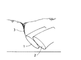
上記した特許文献1に係るポンプゲートは、斯かる要求を満足する為、図17に見られる様に、流体を吸込む吸込み口1,2を流体表面に対して斜め下向きとし、吸込み口真上にある流体を吸込む流れを減速させることになり、渦の発生の抑止、空気の吸込みを防止し、流体を低水位迄安定して吸込むことができる様にしている。
In order to satisfy such a requirement, the pump gate according to Patent Document 1 described above has the
然し乍ら、支川の水位が低水位となった場合、或は支川への流入流量が多くない場合は、2つの水中ポンプの内一方を運転し、他方は休止させるという稼働状態となる。この為、水中ポンプの吸込み口近傍の流体の流れに偏流を生じ、渦が発生し易い状態が発生する。 However, when the water level of the tributary river is low, or when the flow rate of the inflow into the tributary river is not large, one of the two submersible pumps is operated and the other is brought into operation. For this reason, the flow of fluid in the vicinity of the suction port of the submersible pump causes a drift, and a state where vortices are likely to occur occurs.
この為、上記ポンプゲートに於いても所定の水位以下となると図17に見られる様に、空気吸込み渦3が発生し、空気を吸込む現象が発生していた。
For this reason, the
本発明は斯かる実情に鑑み、空気吸込み渦の発生を抑制し、より低水位迄安定して流体を吸込むことができる様にするものである。 In view of such circumstances, the present invention suppresses the generation of air suction vortices and enables fluid to be stably suctioned to a lower water level.
本発明は、流路を開閉する扉体に複数の水中ポンプが設けられたポンプゲートに於いて、前記扉体が前記流路を閉鎖し前記水中ポンプの少なくとも1つが運転されている状態で発生する渦の、渦発生箇所の水面下方に渦が成長して形成される空気吸込み渦を遮断する様に横渦防止板が設けられたポンプゲートに係り、又前記横渦防止板は、前記水中ポンプと水中ポンプとの間に設けられたポンプゲートに係るものである。 The present invention occurs in a pump gate in which a plurality of submersible pumps are provided in a door body that opens and closes a flow path, and the door body closes the flow path and at least one of the submersible pumps is operated. The pump is provided with a lateral vortex prevention plate so as to block an air suction vortex formed by a vortex growing below the surface of the vortex where the vortex is generated. This relates to a pump gate provided between the pump and the submersible pump.
又本発明は、前記横渦防止板は、水平又は略水平に設けられたポンプゲートに係り、又前記横渦防止板は、前記空気吸込み渦の発生範囲を横断する大きさを具備しているポンプゲートに係るものである。 According to the present invention, the horizontal vortex prevention plate relates to a pump gate provided horizontally or substantially horizontally, and the horizontal vortex prevention plate has a size that crosses the generation range of the air suction vortex. It relates to the pump gate.
又本発明は、前記水中ポンプが上流端に吸込みベルを有し、該吸込みベルの軸心は上流に向って下方に傾斜し、下方に向う吸込み口が形成されると共に側面部が開放され、該側面部はコーナ部を有し、前記空気吸込み渦は前記コーナ部に向って成長する様にし、前記横渦防止板はコーナ部の上方で前記空気吸込み渦の発生範囲を横断する様になっているポンプゲートに係るものである。 In the present invention, the submersible pump has a suction bell at the upstream end, the shaft center of the suction bell is inclined downward toward the upstream, the suction port is formed downward, and the side surface is opened. The side surface portion has a corner portion, the air suction vortex grows toward the corner portion, and the transverse vortex prevention plate crosses the generation range of the air suction vortex above the corner portion. This is related to the pump gate.
又本発明は、吸込みベルの上流端は、該吸込みベルの最上部位より下方に位置すると共に前記横渦防止板は前記吸込みベルの最上部位よりも下方に設けられたポンプゲートに係るものである。 According to the present invention, the upstream end of the suction bell is located below the uppermost portion of the suction bell, and the lateral vortex prevention plate relates to a pump gate provided below the uppermost portion of the suction bell. .
又本発明は、渦の発生する箇所の流れを攪乱する正面渦防止板が設けられたポンプゲートに係り、又前記正面渦防止板の水平に対する角度が0°〜90°の範囲であるポンプゲートに係り、又前記正面渦防止板は、前記吸込みベル上面の傾斜方向に対して逆方向に傾斜しているポンプゲートに係るものである。 The present invention also relates to a pump gate provided with a front vortex prevention plate for disturbing the flow at the location where the vortex occurs, and the angle of the front vortex prevention plate with respect to the horizontal is in the range of 0 ° to 90 °. In addition, the front vortex prevention plate relates to a pump gate that is inclined in a direction opposite to an inclination direction of the upper surface of the suction bell.
更に又本発明は、流路を開閉する扉体に複数の水中ポンプが設けられたポンプゲートに於いて、該ポンプゲートの下流側の水位を検出する下流側水位計と、前記ポンプゲートの上流側の水位を検出する上流側水位計と、前記両水位計の検出水位に基づき前記水中ポンプを駆動する制御装置とを具備し、前記ポンプゲートの閉鎖状態で上流側の水位が下流側より低く、空気吸込み渦の発生する水位を越えた水位で前記水中ポンプが運転され、空気吸込み渦の発生する水位以下で前記水中ポンプが停止されるポンプゲートの運転方法に係るものである。 Furthermore, the present invention relates to a pump gate in which a plurality of submersible pumps are provided in a door body that opens and closes a flow path, a downstream water level meter that detects a water level downstream of the pump gate, and an upstream of the pump gate. An upstream water level meter for detecting the water level on the side, and a control device for driving the submersible pump based on the detected water levels of both water level meters, and the upstream water level is lower than the downstream side when the pump gate is closed. Further, the present invention relates to a pump gate operating method in which the submersible pump is operated at a water level exceeding the water level where air suction vortices are generated, and the submersible pump is stopped below the water level where air suction vortices are generated.
本発明によれば、流路を開閉する扉体に複数の水中ポンプが設けられたポンプゲートに於いて、前記扉体が前記流路を閉鎖し前記水中ポンプの少なくとも1つが運転されている状態で発生する渦の、渦発生箇所の水面下方に渦が成長して形成される空気吸込み渦を遮断する様に横渦防止板が設けられたので、水面に発生した渦が成長して下方に延びるのを抑止し、空気吸込み渦が水中ポンプの吸込み口に達することを防止する。 According to the present invention, in a pump gate in which a plurality of submersible pumps are provided in a door body that opens and closes a flow path, the door body closes the flow path and at least one of the submersible pumps is operated. Since a side vortex prevention plate is provided to block the air suction vortex formed by the vortex growing below the water surface of the vortex generation site, the vortex generated on the water surface grows downward Suppresses the extension and prevents the air suction vortex from reaching the suction port of the submersible pump.
又本発明によれば、渦の発生する箇所の流れを攪乱する正面渦防止板が設けられたので、定常的な渦の発生を防止する。 Further, according to the present invention, since the front vortex preventing plate that disturbs the flow at the location where the vortex is generated is provided, the generation of a steady vortex is prevented.
又本発明によれば、流路を開閉する扉体に複数の水中ポンプが設けられたポンプゲートに於いて、該ポンプゲートの下流側の水位を検出する下流側水位計と、前記ポンプゲートの上流側の水位を検出する上流側水位計と、前記両水位計の検出水位に基づき前記水中ポンプを駆動する制御装置とを具備し、前記ポンプゲートの閉鎖状態で上流側の水位が下流側より低く、空気吸込み渦の発生する水位を越えた水位で前記水中ポンプが運転され、空気吸込み渦の発生する水位以下で前記水中ポンプが停止されるので、低水位で水中ポンプが空気を吸込むことが防止されるという優れた効果を発揮する。 According to the present invention, in a pump gate in which a plurality of submersible pumps are provided in a door body that opens and closes a flow path, a downstream water level meter that detects a downstream water level of the pump gate, and the pump gate An upstream water level meter for detecting the upstream water level, and a control device for driving the submersible pump based on the detected water levels of the two water level meters, and the upstream water level from the downstream side when the pump gate is closed. The submersible pump is operated at a water level lower than the water level where the air suction vortex is generated, and the submersible pump is stopped below the water level where the air suction vortex is generated. It has an excellent effect of being prevented.
以下、図面を参照しつつ本発明を実施する為の最良の形態を説明する。 The best mode for carrying out the present invention will be described below with reference to the drawings.
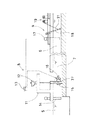
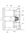
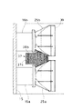
先ず、図1に於いて、ポンプゲート設備についての概略を説明する。 First, an outline of the pump gate facility will be described with reference to FIG.
図中、5は本川、6は支川(流路)又は水路(支川と称す)を示し、該支川6の前記本川5との合流口7にポンプゲート8が設けられ、該ポンプゲート8の上流にスクリーン装置9が設けられている。
In the figure, 5 indicates a main river, 6 indicates a tributary (flow channel) or water channel (referred to as a tributary), and a
前記ポンプゲート8について説明する。
The
前記合流口7に操作台11が設けられ、該操作台11にはゲート開閉装置12、制御装置13、本川用水位計14が設けられ、前記ゲート開閉装置12は前記制御装置13によって駆動が制御され、前記本川用水位計14で検出された前記本川5の水位は前記制御装置13に送出される様になっている。該制御装置13には、前記本川5の最高水位、最低水位、前記支川6の最高水位、最低水位が設定入力されており、これら設定値と、前記本川用水位計14、後述する支川用水位計17が検出する水位との比較で前記ゲート開閉装置12、水中ポンプ16(後述)の駆動停止を制御する様になっている。
An operation table 11 is provided at the
又、前記合流口7を開閉する扉体15が設けられ、該扉体15は前記ゲート開閉装置12に連結され、昇降可能となっている。前記扉体15には前記水中ポンプ16が2組並設されている。該水中ポンプ16は前記制御装置13によって駆動が制御される。
Further, a
前記扉体15の上流には、前記支川用水位計17が設けられ、前記支川6の水位が検出されると共に検出された水位は前記制御装置13に送出される様になっている。
The tributary
前記スクリーン装置9は、上端を回転自在に支持されたスクリーン18を具備し、該スクリーン18は巻上げ装置19にワイヤ21により連結されており、前記巻上げ装置19が前記ワイヤ21を巻取り、或は繰出すことで、前記スクリーン18が前記支川6から引上げられ、或は没水する様になっている。
The screen device 9 includes a
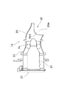
図2は、前記水中ポンプ16の断面図を示している。
FIG. 2 shows a sectional view of the
前記扉体15を貫通する様に円筒状のケーシング22が設けられる。該ケーシング22は水平な軸心を有し、該ケーシング22にはポンプモータ23が同心となる様に支持され、該ポンプモータ23の先端(支川6の上流側)には羽根車24が設けられている。又、前記ケーシング22の上流端には吸込みベル25が設けられ、該吸込みベル25は上流側に向って下降する軸心を有している。
A
前記吸込みベル25の上面部は、先端に向って下降する様延出する湾曲面によって形成され、少なくとも上面の上流端部は上流側に向って下降する様傾斜している。前記吸込みベル25の下面部は前記上面部に比して短く、上流側に向って下降する様傾斜しており、前記上面部、前記下面部、及び該上面部、下面部に連続する側面部とにより斜め下方に向って開口する吸込み口26が形成される。
The upper surface portion of the
尚、前記吸込みベル25の上流端は前記ケーシング22の最上部位、及び前記吸込みベル25の上面湾曲面の最上部位より下方に位置しており、水位が低下し、前記ケーシング22の上部、前記吸込みベル25の上面部が水から露出しても前記吸込み口26は水中に没している状態が保たれる様になっている。
The upstream end of the
又、前記吸込みベル25の側面部は上流端側から大きく抉られ、該側面部には開口部26aが形成される。該開口部26aは最奥部にコーナ部26bを有している。
Further, the side surface portion of the
前記吸込みベル25は斜め下方に開口すると共に側面が開口されていることから、前記吸込み口26は正面から水を吸込むと共に前記開口部26aの側方からも水を吸込む様になっており、特に側方から水を吸込む様にしたことで、正面から吸込む水の流速を低減し、渦の発生ができにくい様にしている。
Since the
前記ケーシング22の下流端には逆止弁27が設けられ、該逆止弁27は上端が回転自在に支持され、前記本川5側からの水圧で、前記ケーシング22の下流端の開口部を閉塞する様になっている。尚、前記逆止弁27は吐出される水の圧力で開放される様になっている。
A
ポンプゲート設備の作動の概略を説明する。 An outline of the operation of the pump gate facility will be described.
前記スクリーン18は漂流物等の異物が前記本川5或は前記水中ポンプ16に流入しない様に前記支川6の水中に没水されている。
The
前記本川用水位計14により前記本川5の水位が検出され、又前記支川用水位計17により前記支川6の水位が検出され、検出結果はそれぞれ前記制御装置13に送出される。該制御装置13では、前記本川用水位計14と、前記支川用水位計17が検出した水位を比較し、前記本川5の水位が前記支川6の水位より高くなると、前記本川5から前記支川6への逆流を防止する為、前記ゲート開閉装置12を駆動して、前記扉体15を降下させ、前記合流口7を閉塞する。前記水中ポンプ16を運転していない場合は、前記逆止弁27が前記水中ポンプ16の吐出口を閉塞している。
The main river
更に、前記本川5の水位が上昇し、前記本川用水位計14が所定の水位を検出すると、前記ポンプゲート8が駆動し、前記扉体15が閉じられる。更に、前記支川用水位計17が最低水位以上であることを検出すると、前記制御装置13により前記水中ポンプ16が駆動され、該水中ポンプ16により前記支川6側の水が前記本川5側に強制吐出される。
Further, when the water level of the
更に、前記支川用水位計17が最低水位を検出すると、前記水中ポンプ16が停止される。最低水位は空気吸込み渦3(図17参照)が発生しない最も低い水位を言い、前記水中ポンプ16は最低水位以上で運転される。
Further, when the tributary
上記した様に、前記支川用水位計17の水位が最低水位以下となると、渦の発生、空気の吸込みによって、前記水中ポンプ16の安定運転が損われ、或は渦の影響による振動で該水中ポンプ16が損傷する虞れがある。
As described above, when the water level of the tributary
ここで、空気の吸込みの原因となる、渦の発生について説明する。 Here, generation | occurrence | production of the vortex which causes the suction | inhalation of air is demonstrated.
本発明者は2つのポンプが並設されたポンプゲートに於いて、一方のポンプのみを運転した場合に渦が発生し易いことを確認し、又一方のポンプのみを運転した場合に発生する渦について解析した。 The present inventor confirmed that a vortex is easily generated when only one pump is operated in a pump gate in which two pumps are arranged side by side, and a vortex generated when only one pump is operated. Was analyzed.
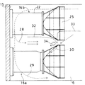
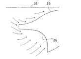
図3は、2組の水中ポンプ16a,16bの内、図中下側の該水中ポンプ16aが運転された場合の該水中ポンプ16a,16b周辺に発生する平面的な流れ、及び平面的な流れに起因する渦を示し、図中破線で示す矢印は水流の底の流れ(以下底流と称す)28,29,30を示し、実線で示す矢印は水流の表面の流れ(以下表流と称す)32,33を示している。
FIG. 3 shows a planar flow generated around the submersible pumps 16a and 16b and a planar flow when the
前記吸込み口26の側方を通過した前記底流は下流側に流れ前記扉体15に当り、該扉体15に沿って流れ、一部の前記底流28は前記水中ポンプ16aと水中ポンプ16b間を上流に向って流れ、図4中A部で偏向した前記底流30となり前記吸込み口26から吸引される。又、前記水中ポンプ16aの下方を通過する前記底流29は、前記支川6の側壁に沿って偏向し、上流に向って流れ、前記吸込み口26より吸引される。
The bottom flow that has passed through the side of the
前記水中ポンプ16aと水中ポンプ16bとの間の表面は上流に向って流れ、前記吸込みベル25によって流路が狭められることから、該吸込みベル25のB部(図4参照)に当って該吸込みベル25,25の間で図中時計方向に回転する。又、前記吸込み口26の上流側からの前記表流33が前記吸込みベル25の上面、C部(図4参照)に当って左右に分れ、一部が前記吸込みベル25,25の間に流れ込む。この為、前記表流32と前記表流33によって渦34が前記吸込みベル25の側方に発生する。
Since the surface between the
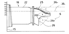
尚、該渦34の水面での発生範囲は、図7に示される如く、前記吸込みベル25の上流端近傍より下流位置から前記ケーシング22の先端部近傍迄となっている。
The generation range of the
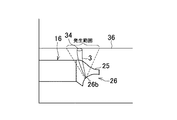
前記渦34が成長すると前記底流30との相乗作用で、水面から前記吸込み口26に達する連続した空気吸込み渦となる。尚、前記吸込み口26には側面部に前記開口部26aが形成されていることから、前記渦34が発生し、前記空気吸込み渦3に成長する場合、該空気吸込み渦3は前記吸込み口26側方の前記コーナ部26bに向って延び、該コーナ部26bに達する。前記渦34が該コーナ部26b、即ち前記開口部26aに達した場合、該開口部26aからの空気の吸込みが発生する。
When the
而して、前記渦34が前記空気吸込み渦3に成長する範囲は、前記渦34の水面での発生範囲と前記コーナ部26bとを結ぶ略3角形の範囲となっている(図7参照)。
Thus, the range in which the
尚、図4中、36Lは低水位の水面、36Hは高水位の水面を示している。 In FIG. 4, 36L indicates a low water level and 36H indicates a high water level.
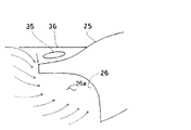
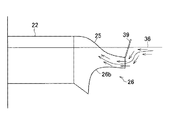
次に、図5、図6により、吸込みベル25の上流側の流れについて説明する。尚、図中、36は水面を示している。
Next, the flow on the upstream side of the
水位が高い状態では、前記吸込み口26に吸込まれる流れと、前記吸込みベル25の上面に沿って上昇する流れが発生する。ところが水位が低下すると、前記吸込みベル25で流れが堰き止められるので、該吸込みベル25の上側に淀み35を生じ、更に前記吸込み口26の上流端から該吸込み口26に向って沈込む流れが発生するので、前記吸込みベル25の上流端に図17で示した様に、前記空気吸込み渦3が発生し、前記吸込み口26からの空気の吸込みが発生する。
When the water level is high, a flow sucked into the
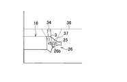
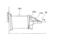
本発明では、上記した前記空気吸込み渦3の発生状況を考慮して、前記渦34の成長、及び連続、持続性を抑制、防止する手段として、図9に示される様に前記水中ポンプ16aと水中ポンプ16b間に横渦防止板37を設け、図10、図11に示される様に正面渦防止板39を設ける。
In the present invention, as a means for suppressing and preventing the growth, continuity, and sustainability of the
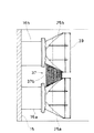
先ず、図8〜図11に於いて前記横渦防止板37について説明する。
First, the lateral
前記水中ポンプ16aの吸込みベル25aと前記水中ポンプ16bの吸込みベル25b間に横渦防止板37aが設けられている。該横渦防止板37aは2分割構造であり、中央にスリット部38aが形成されている。又、前記横渦防止板37aは水平又は略水平に設けられる。
A transverse
該横渦防止板37aの取付け位置は、前記支川6の底面から所要高さの位置、例えば前記ケーシング22の中心線から20mm程度上方、或は最低水位となった状態で水面から50mm下方の位置であり、前記吸込みベル25の上部、前記ケーシング22の上部が露出した状態でも、水面下に没した状態となる。更に図8で示される様に、前記コーナ部26bの上方に位置し、上述した前記渦34が前記空気吸込み渦3に成長する範囲を横断する位置となっており、更に水平方向の長さは前記3角形の範囲を越えるものとなっている。
The horizontal
前記横渦防止板37aは、図示される様にパンチングメタル等の多孔板でもよく或は孔のない単なる平板であってもよい。
The lateral
前記横渦防止板37aを設けることで、図3で示される水面での水の回転による前記表流32,33によって発生する前記渦34が成長して下方に延びることが前記横渦防止板37によって遮断され、前記底流30との相乗作用を抑制する。
By providing the lateral
図12、図13は前記横渦防止板37の他の例を示しており、図12で示す横渦防止板37bはスリット部38aがなく、一枚の横渦防止板37bが前記吸込みベル25aと吸込みベル25b間に掛渡って設けられたものである。又図13で示す横渦防止板37cは、前記横渦防止板37が吸込みベル25の更に下流側に延びる延出部38bを有しているものである。
FIGS. 12 and 13 show another example of the lateral
いずれの場合も前記横渦防止板37は、空気吸込み渦3の発生範囲を横断し、渦34が前記空気吸込み渦3に成長するのを抑制するので、該空気吸込み渦3の発生が防止される。
In any case, the transverse
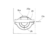
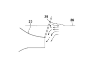
次に、前記正面渦防止板39について図9〜図11に於いて説明する。
Next, the front
前記吸込みベル25の上流端に前記正面渦防止板39を、水平に対して所要の角度αを成す様に固着する。角度αは0°又は0°近傍から90°迄の所要の角度、例えば70°が選択される。前記正面渦防止板39は、前記吸込みベル25の上面先端部の傾斜に対して逆方向に傾斜する状態となる。
The front
図14、図15に於いて、前記正面渦防止板39の作用について説明する。
The operation of the front
前記正面渦防止板39は、下流に向って流れる表流を急激に堰止める。堰止められた表流は前記正面渦防止板39に沿って潜込み、更に前記吸込みベル25の上面に沿って上昇する流れとなる。
The front
上記した様に、前記正面渦防止板39と前記吸込みベル25上面の傾斜が逆方向であるので、前記正面渦防止板39から前記吸込みベル25に流れる過程で流れ方向の大きな変化が生じる。この為、前記正面渦防止板39は表流に対して大きな抵抗となり、該正面渦防止板39への衝突で水の跳ね返りが発生し、流れを乱し、表面を波立たせる。従って、図17で示される空気吸込み渦3の発生が防止される。
As described above, since the front
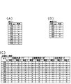
図16(A)、図16(B)、図16(C)は、実験で得られた前記横渦防止板37、及び前記正面渦防止板39の効果を示している。図中の枡に○が記されているのは、前記空気吸込み渦3の発生がなかったことを示し、×が記されているものは該空気吸込み渦3の発生があったことを示している。又、図中、横板1は横渦防止板37a、横板2は横渦防止板37b、横板3は横渦防止板37cを示し、正面板は正面渦防止板39を示している。
FIG. 16A, FIG. 16B, and FIG. 16C show the effects of the lateral
図16(A)は、前記横渦防止板37、前記正面渦防止板39を設けない場合の水位と渦の発生との関係を示すものである(図4参照)。
FIG. 16A shows the relationship between the water level and the generation of vortices when the lateral
前記横渦防止板37、正面渦防止板39のいずれも設けない場合は、水位が600mmより下がると有害な空気吸込み渦が発生している。
When neither the horizontal
図16(B)は、前記横渦防止板37を設けた場合を示しており、該横渦防止板37を設けた場合は、水位が480mmで有害な空気吸込み渦が発生している。即ち、前記横渦防止板37を設けることで、120mm水位が低下する迄、前記水中ポンプ16の運転が可能となった。
FIG. 16B shows a case where the horizontal
又、図16(C)は、前記横渦防止板37a,37b,37cを設け、更に前記正面渦防止板39を設けた場合で、該正面渦防止板39の角度をα=70°,30°,0°,とした場合の渦の発生の状態を示している。
FIG. 16C shows the case where the lateral
図16(C)の結果と図16(A)の結果とを比較することで明らかな様に、いずれの場合も、有害な空気吸込み渦が発生する水位は低下し、前記横渦防止板37、前記正面渦防止板39の渦発生抑制効果が確認することができる。特に、該正面渦防止板39の角度が0°、前記横渦防止板37aが設けられた場合に、水位が430mmの場合でも尚有害な前記空気吸込み渦3が発生していなく、大きな渦発生抑制効果が得られることが分る。
As is clear by comparing the result of FIG. 16C and the result of FIG. 16A, in any case, the water level at which harmful air suction vortices are generated decreases, and the lateral
又、前記正面渦防止板39がα=70°で、横渦防止板37a、横渦防止板37bの場合で、水位600mmの時、及び前記正面渦防止板39がα=30°で横渦防止板37bの場合で水位600mm,550mmの時にそれぞれ渦が発生したが、軽微なものであり、実用上差支えないものであった。
Further, when the front
前記水中ポンプ16の運転については、図1に於いて説明したが、前記制御装置13に設定入力する最低水位は、図16(C)の正面渦防止板39の角度α=70°の場合では475mmであり、本川5の水位が支川6の水位より高い場合で、支川6の水位が475mmとなった場合に、前記水中ポンプ16の運転が中止され、支川6の水位が475mmを越えた場合に、前記水中ポンプ16の運転が行われる。尚、図16で示す数値は、一例であり、支川6の規模、ポンプゲートの規模により異なることは言う迄もない。
The operation of the
尚、前記扉体15に設けられる前記水中ポンプ16の数は2組に限らず、3組の場合も考えられ、この場合前記横渦防止板37はそれぞれの前記水中ポンプ16の間に設けられる。又、上記実施の形態では前記横渦防止板37が、前記水中ポンプ16,16間に設けられたが、その他にも渦の発生する箇所に渦の延長を横断又は遮断する様に、又流れを攪乱する様に設けてもよい。
Note that the number of submersible pumps 16 provided on the
3 空気吸込み渦
5 本川
6 支川
7 合流口
12 ゲート開閉装置
13 制御装置
14 本川用水位計
15 扉体
16 水中ポンプ
17 支川用水位計
23 ポンプモータ
25 吸込みベル
26 吸込み口
28,29,30 底流
32,33 表流
34 渦
37 横渦防止板
38a スリット部
38b 延出部
39 正面渦防止板
DESCRIPTION OF
Claims (10)
Priority Applications (1)
| Application Number | Priority Date | Filing Date | Title |
|---|---|---|---|
| JP2005068674A JP2005290972A (en) | 2004-03-12 | 2005-03-11 | Pump gate and operation method of pump gate |
Applications Claiming Priority (2)
| Application Number | Priority Date | Filing Date | Title |
|---|---|---|---|
| JP2004071228 | 2004-03-12 | ||
| JP2005068674A JP2005290972A (en) | 2004-03-12 | 2005-03-11 | Pump gate and operation method of pump gate |
Publications (1)
| Publication Number | Publication Date |
|---|---|
| JP2005290972A true JP2005290972A (en) | 2005-10-20 |
Family
ID=35324211
Family Applications (1)
| Application Number | Title | Priority Date | Filing Date |
|---|---|---|---|
| JP2005068674A Pending JP2005290972A (en) | 2004-03-12 | 2005-03-11 | Pump gate and operation method of pump gate |
Country Status (1)
| Country | Link |
|---|---|
| JP (1) | JP2005290972A (en) |
Cited By (4)
| Publication number | Priority date | Publication date | Assignee | Title |
|---|---|---|---|---|
| WO2016178387A1 (en) * | 2015-05-01 | 2016-11-10 | 株式会社石垣 | Horizontal shaft submersible pump and suction cover used for horizontal shaft submersible pump |
| JP2017172406A (en) * | 2016-03-22 | 2017-09-28 | 株式会社東芝 | Hydro machinery equipment |
| CN111139800A (en) * | 2020-01-17 | 2020-05-12 | 华北水利水电大学 | Adjustable eddy elimination and rectification device and eddy elimination and rectification method |
| KR20200115062A (en) * | 2019-03-27 | 2020-10-07 | 가부시끼 가이샤 구보다 | Suction cover, horizontal shaft pump, pump gate, and pump gate operating method |
-
2005
- 2005-03-11 JP JP2005068674A patent/JP2005290972A/en active Pending
Cited By (13)
| Publication number | Priority date | Publication date | Assignee | Title |
|---|---|---|---|---|
| KR102004207B1 (en) * | 2015-05-01 | 2019-07-26 | 가부시키가이샤 이시가키 | Horizontal shaft submersible pump and suction cover used for horizontal shaft submersible pump |
| KR20170127007A (en) * | 2015-05-01 | 2017-11-20 | 가부시키가이샤 이시가키 | Horizontal shaft submersible pump and suction cover used for horizontal shaft submersible pump |
| CN107429701A (en) * | 2015-05-01 | 2017-12-01 | 株式会社石垣 | Horizontal shaft submersible pumps and suction hoods for horizontal shaft submersible pumps |
| JPWO2016178387A1 (en) * | 2015-05-01 | 2018-02-08 | 株式会社石垣 | Horizontal axis submersible pump and suction cover used for horizontal axis submersible pump |
| CN107429701B (en) * | 2015-05-01 | 2019-02-01 | 株式会社石垣 | Horizontal axis submersible pumps and suction hoods for horizontal axis submersible pumps |
| WO2016178387A1 (en) * | 2015-05-01 | 2016-11-10 | 株式会社石垣 | Horizontal shaft submersible pump and suction cover used for horizontal shaft submersible pump |
| JP2017172406A (en) * | 2016-03-22 | 2017-09-28 | 株式会社東芝 | Hydro machinery equipment |
| KR20200115062A (en) * | 2019-03-27 | 2020-10-07 | 가부시끼 가이샤 구보다 | Suction cover, horizontal shaft pump, pump gate, and pump gate operating method |
| CN111749930A (en) * | 2019-03-27 | 2020-10-09 | 株式会社久保田 | Suction hood, horizontal axis pump, pump gate and operation method of pump gate |
| CN111749930B (en) * | 2019-03-27 | 2023-09-12 | 株式会社久保田 | Suction hood, horizontal axis pump, pump gate and pump gate operation method |
| KR102778822B1 (en) * | 2019-03-27 | 2025-03-12 | 가부시끼 가이샤 구보다 | Suction cover, horizontal shaft pump, pump gate, and pump gate operating method |
| CN111139800A (en) * | 2020-01-17 | 2020-05-12 | 华北水利水电大学 | Adjustable eddy elimination and rectification device and eddy elimination and rectification method |
| CN111139800B (en) * | 2020-01-17 | 2024-03-12 | 华北水利水电大学 | Adjustable vortex eliminating and rectifying device and vortex eliminating and rectifying method |
Similar Documents
| Publication | Publication Date | Title |
|---|---|---|
| TWI704287B (en) | Horizontal shaft submersible pump and suction cover for horizontal shaft submersible pump | |
| US4579506A (en) | Horizontal-inflow, vertical-outflow cross-flow turbine | |
| JP5318240B2 (en) | Suction tank | |
| JP6953317B2 (en) | Pump with vortex suppressor | |
| CN111749930B (en) | Suction hood, horizontal axis pump, pump gate and pump gate operation method | |
| JP2008175162A (en) | Pump device and pump gate device | |
| JP2005290972A (en) | Pump gate and operation method of pump gate | |
| KR20160064314A (en) | Gate pump apparatus | |
| JP4690134B2 (en) | Vertical shaft pump and pump station | |
| JP4463484B2 (en) | Vertical shaft pump | |
| JP2006194100A (en) | Swirl prevention device | |
| EP0501012B1 (en) | Drainage pump | |
| JP3998148B2 (en) | Suction cover structure of horizontal shaft pump | |
| JP4566852B2 (en) | Horizontal axis pump, pump gate equipment, drainage station | |
| JP4657845B2 (en) | Horizontal shaft pump | |
| JP4628029B2 (en) | Rectifying member of submersible pump for pump gate | |
| JPH05172084A (en) | Vertical shaft pump | |
| JP2004360503A (en) | Horizontal axis pump suction cover structure | |
| JPS63189688A (en) | Multiple vertical shaft pump operation equipment | |
| JP2001041200A (en) | Pump device with vortex prevention device | |
| JP2524872Y2 (en) | Full-speed standby operation pump | |
| JP4042375B2 (en) | Vertical pump suction tank | |
| JP6997641B2 (en) | Pump with vortex suppressor | |
| JP2004044138A (en) | Pump gate | |
| JP7178194B2 (en) | Suction cover, horizontal shaft pump and pump gate |
Legal Events
| Date | Code | Title | Description |
|---|---|---|---|
| A521 | Written amendment |
Effective date: 20060417 Free format text: JAPANESE INTERMEDIATE CODE: A821 |
|
| A711 | Notification of change in applicant |
Free format text: JAPANESE INTERMEDIATE CODE: A711 Effective date: 20060417 |
|
| RD02 | Notification of acceptance of power of attorney |
Free format text: JAPANESE INTERMEDIATE CODE: A7422 Effective date: 20060417 |
|
| A521 | Written amendment |
Free format text: JAPANESE INTERMEDIATE CODE: A821 Effective date: 20060417 |
|
| A521 | Written amendment |
Effective date: 20080110 Free format text: JAPANESE INTERMEDIATE CODE: A821 |
|
| A621 | Written request for application examination |
Free format text: JAPANESE INTERMEDIATE CODE: A621 Effective date: 20080110 |
|
| A977 | Report on retrieval |
Free format text: JAPANESE INTERMEDIATE CODE: A971007 Effective date: 20090824 |
|
| A131 | Notification of reasons for refusal |
Effective date: 20090908 Free format text: JAPANESE INTERMEDIATE CODE: A131 |
|
| A02 | Decision of refusal |
Effective date: 20100309 Free format text: JAPANESE INTERMEDIATE CODE: A02 |