KR20160064314A - Gate pump apparatus - Google Patents
Gate pump apparatus Download PDFInfo
- Publication number
- KR20160064314A KR20160064314A KR1020140167373A KR20140167373A KR20160064314A KR 20160064314 A KR20160064314 A KR 20160064314A KR 1020140167373 A KR1020140167373 A KR 1020140167373A KR 20140167373 A KR20140167373 A KR 20140167373A KR 20160064314 A KR20160064314 A KR 20160064314A
- Authority
- KR
- South Korea
- Prior art keywords
- pump
- impeller
- casing
- water
- gate
- Prior art date
Links
Images


Classifications
-
- E—FIXED CONSTRUCTIONS
- E02—HYDRAULIC ENGINEERING; FOUNDATIONS; SOIL SHIFTING
- E02B—HYDRAULIC ENGINEERING
- E02B7/00—Barrages or weirs; Layout, construction, methods of, or devices for, making same
- E02B7/20—Movable barrages; Lock or dry-dock gates
-
- F—MECHANICAL ENGINEERING; LIGHTING; HEATING; WEAPONS; BLASTING
- F04—POSITIVE - DISPLACEMENT MACHINES FOR LIQUIDS; PUMPS FOR LIQUIDS OR ELASTIC FLUIDS
- F04D—NON-POSITIVE-DISPLACEMENT PUMPS
- F04D13/00—Pumping installations or systems
- F04D13/02—Units comprising pumps and their driving means
- F04D13/06—Units comprising pumps and their driving means the pump being electrically driven
- F04D13/08—Units comprising pumps and their driving means the pump being electrically driven for submerged use
-
- F—MECHANICAL ENGINEERING; LIGHTING; HEATING; WEAPONS; BLASTING
- F04—POSITIVE - DISPLACEMENT MACHINES FOR LIQUIDS; PUMPS FOR LIQUIDS OR ELASTIC FLUIDS
- F04D—NON-POSITIVE-DISPLACEMENT PUMPS
- F04D29/00—Details, component parts, or accessories
- F04D29/40—Casings; Connections of working fluid
- F04D29/52—Casings; Connections of working fluid for axial pumps
- F04D29/54—Fluid-guiding means, e.g. diffusers
-
- Y—GENERAL TAGGING OF NEW TECHNOLOGICAL DEVELOPMENTS; GENERAL TAGGING OF CROSS-SECTIONAL TECHNOLOGIES SPANNING OVER SEVERAL SECTIONS OF THE IPC; TECHNICAL SUBJECTS COVERED BY FORMER USPC CROSS-REFERENCE ART COLLECTIONS [XRACs] AND DIGESTS
- Y10—TECHNICAL SUBJECTS COVERED BY FORMER USPC
- Y10S—TECHNICAL SUBJECTS COVERED BY FORMER USPC CROSS-REFERENCE ART COLLECTIONS [XRACs] AND DIGESTS
- Y10S415/00—Rotary kinetic fluid motors or pumps
- Y10S415/901—Drilled well-type pump
Landscapes
- Engineering & Computer Science (AREA)
- General Engineering & Computer Science (AREA)
- Mechanical Engineering (AREA)
- Structural Engineering (AREA)
- Civil Engineering (AREA)
- Structures Of Non-Positive Displacement Pumps (AREA)
- Barrages (AREA)
Abstract
Description
The present invention relates to a gate pump apparatus, particularly a gate pump apparatus having a horizontal axis, capable of preventing foreign water from entering and discharging domestic water to the outside.
In order to prevent the infiltration of foreign water and to discharge the domestic water to the outside water, the water gate (gate) is installed in the river or the reservoir. At this time, An underwater pump is installed. However, a submersible pump that is disposed directly on a water gate or the like and installed in a waterway has been proposed in various ways as represented by, for example, a gate pump. This submersible pump generally comprises a pump inlet casing, an impeller, a motor, a pre-guiding or post-guiding wing, a discharge casing, a flap valve, .
Pumps are generally arranged vertically or horizontally, and for either type of pumping and drainage pump, it is inevitable to suck the foreign material into the pump. When this foreign matter, that is, the trash flow, is sucked into the pump, it adheres to the impeller, the hub, and the like, which hinders pump operation.
There is no problem if the trash is sucked into the pump and passed along with the water. However, when the impeller or the hub of the pump does not always adhere to the impeller or the hub, or when the impeller and the casing or the liner are caught in the gap, the safety device such as the overload prevention device operates by increasing the rotational power, This is a problem if it happens frequently.
In order to prevent these problems, conventionally, dust removal equipment is installed in the upstream water channel of the pump to prevent the flow of the waste so as to prevent foreign substances from being sucked into the pump as much as possible. It is also known on the pump side that a retracting blade is used to increase the clearance between the liner and the liner in order to improve the penetration of the waste into the pump. In addition, many water gates are installed in waterways such as rivers for purposes such as flood control. There are drain holes in this gate, and many gate are equipped with an underwater pump. A submersible pump is placed directly at the gate, which is to forcibly drain the running water of the channel when the gate is closed. There are many types of submersible pumps, and the pump, which is usually installed on the gate, is called a gate pump.
These submersible pumps are mainly of the type that is different depending on the direction in which the pump rotation shaft is installed, and there are those of the horizontal axis type and the vertical axis type. In addition, in order to improve the suction performance of the submersible pump, it is necessary to install the suction port as close as possible to the bed (or bottom of the water channel). When the water level of the underwater pump is lowered due to the water channel side, if the immersion depth required for the submersible pump is not secured, a swirl, an underwater swirling, a swirling flow, Inhalation of water becomes worse. The air intake vortex, the underwater vortex, and the swirling flow of the air swirl, the cavitation, the drop of the head are lowered, and the performance of the submersible pump, the noise, vibration, Causing mechanical problems such as wing erosion.
In the vertical axis type, since the pump inlet is opened toward the bottom, the pump device is not installed by deeply pouring the water to the bottom, and there is little fear of cavitation due to lack of water and the pump operation is stable. In recent years, most of the transverse axis gate pumps are used. In the present invention, the gate pump (axial pump, or the like) of the horizontal axis is used. Impeller pump).
The gate pump device is provided with a guide vane for guiding the vortical flow to the laminar flow in order to avoid the vortex flow of the water discharged from the impeller so that the pump efficiency is lowered, specifically, a so-called front or rear guide vane is radially installed before and after the impeller .
An example of installing the front guide vane (the side where the water is discharged from the impeller is referred to as "transposition") is an axial flow pump disclosed in Korean Patent Publication No. 1994-0021940. The guide wing is a hydraulic drive type gate pump disclosed in Korean Patent No. 10-0691508, and a system in which both a front and a rear guide wing are applied is disclosed in Korean Patent Publication No. 1995-0005003, .
However, in the case of the above-mentioned front guide vane, the flow of the swirling flow passing through the impeller flows in the direction opposite to the rotation of the impeller, so that the efficiency deterioration can not be avoided. Recently, The flow through the impeller is made to flow in the same direction so that the water flowing through the impeller can flow stably and the pump efficiency can be improved.
However, as can be seen in Korean Patent Publication No. 10-0691508 and Korean Patent Publication No. 1995-0005003 which apply a posterior guide wing, the
Accordingly, the present invention has been made in view of the above-mentioned problems, and it is an object of the present invention to provide a pumping system that minimizes fluid resistance by minimizing fluid flow by expanding the inflow channel of water to be drained, The present invention provides a gate pump apparatus capable of improving the performance of a gate pump.
According to an aspect of the present invention, there is provided a pump casing including a pump casing having a pump inlet for introducing water for drainage into a through hole formed in a water gate, And a motor for rotationally driving the impeller, characterized in that the pump pump has a pump inlet at a position spaced forward from the front end hub cap of the impeller casing, And a plurality of posture guide vanes having one end fixed and the other end extending toward the center of the pump shaft and having a free end for forming a space at the center thereof are radially arranged.
In the present invention as described above, in the conventional posture guide vane, one end is fixed to the inner surface of the pump casing, and the other end is extended radially toward the center of the pump shaft to be supported on the outer circumferential surface of the impeller casing. One end of the pump casing is fixed to the inner surface of the pump casing at a position spaced forward from the impeller casing, and the other end of the pump casing is radially arranged so as to have a free end extending toward the pump shaft center, By providing a plurality of pipes, a space is formed at the center and the inflow channel is expanded, so that the flow of the wired line is smooth and the loss can be minimized, thereby improving the pump drainage efficiency.
Figure 1 is a prior art.
FIG. 2 is a view showing a water channel in which a gate pump device according to the present invention is installed at a gate.
3 is a cross-sectional view showing a gate pump apparatus according to the present invention.
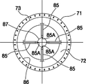
4 is a side view (front view) of the casing of the gate pump apparatus according to the present invention.
In the following detailed description, reference is made to the accompanying drawings which show, by way of illustration, specific embodiments in which the invention may be practiced.
These embodiments are described in sufficient detail to enable those skilled in the art to practice the invention. It should be understood that the various embodiments of the present invention are not necessarily mutually exclusive, even if different. By way of example, certain aspects, structures, or features described herein in connection with one embodiment may be practiced by other embodiments without departing from the spirit and scope of the invention.
It is also to be understood that the position or arrangement of individual elements within each disclosed embodiment may be modified without departing from the spirit and scope of the invention. The following detailed description is, therefore, not to be taken in a limiting sense, and the scope of the invention is defined only by the appended claims appropriately interpreted and by the full range of equivalents to which such claims pertain. In the drawings, like reference numerals refer to the same or similar functions in the various figures.
3 is a cross-sectional view of a gate pump apparatus according to the present invention, and Fig. 4 is a cross-sectional view of a casing of a gate pump apparatus according to the present invention. Fig. As seen from the side (front side), the term "posterior" in the present invention refers to the forward position of the impeller side into which water is introduced.
2, a conventional automatic vibration damper 61 is provided in front of the channel 60 to filter off the vibration of the water. The automatic vibration damper 61 is provided at the rear of the vibration damper 61 with a water passage 60, And a
The
As shown in Fig. 4, the
The fastening
The
4 is a view of the casing of the gate pump apparatus according to the present invention viewed from a front position in which water is introduced. The
In the present invention as described above, a guide collar, that is, a
The above-described embodiments are merely illustrative of the technical structure of the present invention, and are not intended to limit the scope of the present invention. Although the present invention has been described in detail with reference to exemplary embodiments thereof, it is to be understood that such detailing embodiments of the invention may be modified by those skilled in the art and that part of the technical features may be modified without departing from the spirit of the invention, And such subject matter should be included within the scope of the technical method of the invention claimed below.
60: Waterway (lagoons) 61: Automatic dust collector
62: Hydraulic structure 63: Drain
64: Water gate 65: Gate pump device
66: Hydrological relief 67: Domestic water (side)
68: Outer water (side) 69: Pump
70: flap valve 71: fastening flange
72: inlet 73: casing
74: impeller 75: motor assembly
76: pump side flange 77: valve body
78: Valve side flange 79: Bolt
80: filtering hole 81: fastening means for lifting (ring member)
82: Hoist 83: Fixing bolt
84:
85: post guide guide
86: inner diameter surface 87: space (inflow channel)
Claims (1)
Priority Applications (1)
| Application Number | Priority Date | Filing Date | Title |
|---|---|---|---|
| KR1020140167373A KR20160064314A (en) | 2014-11-27 | 2014-11-27 | Gate pump apparatus |
Applications Claiming Priority (1)
| Application Number | Priority Date | Filing Date | Title |
|---|---|---|---|
| KR1020140167373A KR20160064314A (en) | 2014-11-27 | 2014-11-27 | Gate pump apparatus |
Publications (1)
| Publication Number | Publication Date |
|---|---|
| KR20160064314A true KR20160064314A (en) | 2016-06-08 |
Family
ID=56193342
Family Applications (1)
| Application Number | Title | Priority Date | Filing Date |
|---|---|---|---|
| KR1020140167373A KR20160064314A (en) | 2014-11-27 | 2014-11-27 | Gate pump apparatus |
Country Status (1)
| Country | Link |
|---|---|
| KR (1) | KR20160064314A (en) |
Cited By (4)
| Publication number | Priority date | Publication date | Assignee | Title |
|---|---|---|---|---|
| KR101664269B1 (en) * | 2016-06-27 | 2016-10-11 | 대성펌프공업주식회사 | drainage pump |
| CN109356112A (en) * | 2018-11-23 | 2019-02-19 | 江苏环集团有限公司 | A kind of Novel non-rising stem type screw rod headstock gear |
| CN112253488A (en) * | 2020-10-16 | 2021-01-22 | 扬州大学 | Novel two-stage flexible flap valve device suitable for bidirectional pump station and operation method thereof |
| KR102648851B1 (en) * | 2022-11-22 | 2024-03-20 | 광희엔지니어링 주식회사 | Gate Pump With A Function Of Accelerating The Fluid |
Citations (6)
| Publication number | Priority date | Publication date | Assignee | Title |
|---|---|---|---|---|
| JPS52136401A (en) | 1976-05-11 | 1977-11-15 | Nishida Marine Boiler | Pump gates |
| JPS565883A (en) | 1979-06-29 | 1981-01-21 | Dainippon Toryo Co Ltd | Method of producing fluorescent material |
| KR940021940A (en) | 1993-03-20 | 1994-10-19 | 정구철 | Axial pump |
| KR950005003A (en) | 1993-07-21 | 1995-02-18 | 배순훈 | Manufacturing method of optical path control device for projection image display device |
| KR100691508B1 (en) | 2005-11-28 | 2007-03-09 | 코스모스산업 주식회사 | Hydraulic driven gate pump |
| KR100807944B1 (en) | 2003-07-07 | 2008-02-28 | 가부시키가이샤 미죠타 | Pump |
-
2014
- 2014-11-27 KR KR1020140167373A patent/KR20160064314A/en not_active Application Discontinuation
Patent Citations (6)
| Publication number | Priority date | Publication date | Assignee | Title |
|---|---|---|---|---|
| JPS52136401A (en) | 1976-05-11 | 1977-11-15 | Nishida Marine Boiler | Pump gates |
| JPS565883A (en) | 1979-06-29 | 1981-01-21 | Dainippon Toryo Co Ltd | Method of producing fluorescent material |
| KR940021940A (en) | 1993-03-20 | 1994-10-19 | 정구철 | Axial pump |
| KR950005003A (en) | 1993-07-21 | 1995-02-18 | 배순훈 | Manufacturing method of optical path control device for projection image display device |
| KR100807944B1 (en) | 2003-07-07 | 2008-02-28 | 가부시키가이샤 미죠타 | Pump |
| KR100691508B1 (en) | 2005-11-28 | 2007-03-09 | 코스모스산업 주식회사 | Hydraulic driven gate pump |
Cited By (5)
| Publication number | Priority date | Publication date | Assignee | Title |
|---|---|---|---|---|
| KR101664269B1 (en) * | 2016-06-27 | 2016-10-11 | 대성펌프공업주식회사 | drainage pump |
| CN109356112A (en) * | 2018-11-23 | 2019-02-19 | 江苏环集团有限公司 | A kind of Novel non-rising stem type screw rod headstock gear |
| CN112253488A (en) * | 2020-10-16 | 2021-01-22 | 扬州大学 | Novel two-stage flexible flap valve device suitable for bidirectional pump station and operation method thereof |
| CN112253488B (en) * | 2020-10-16 | 2022-04-19 | 扬州大学 | Novel two-stage flexible flap valve device suitable for bidirectional pump station and operation method thereof |
| KR102648851B1 (en) * | 2022-11-22 | 2024-03-20 | 광희엔지니어링 주식회사 | Gate Pump With A Function Of Accelerating The Fluid |
Similar Documents
| Publication | Publication Date | Title |
|---|---|---|
| CN104061184B (en) | The improvement of pump and the improvement relevant with pump | |
| RU2654923C2 (en) | Apparatus and method for dredging of sediments from seabed | |
| KR20160064314A (en) | Gate pump apparatus | |
| JP5025273B2 (en) | Pump device and pump gate device | |
| JP6892373B2 (en) | Pump with anti-vortex device | |
| KR102327661B1 (en) | Suction guide apparatus for underwater pump | |
| KR102165242B1 (en) | Submerged motor pump | |
| US9651050B2 (en) | Propeller pump and pump station | |
| JP2015078679A (en) | Pump | |
| JP2013122238A (en) | Pump | |
| JP4839974B2 (en) | Resin submersible pump | |
| JP4463484B2 (en) | Vertical shaft pump | |
| CN106545496B (en) | Sleeping suction multi-stage pipeline pump | |
| KR101388462B1 (en) | Mixed flow pump | |
| JP3692339B2 (en) | Column type pump and pump gate | |
| CN211288274U (en) | Vacuum suction device of mining pneumatic dredging dredge pump | |
| JP2019070333A (en) | Submerged pump | |
| KR20160064316A (en) | Flap valve of gate pump device | |
| KR20110101636A (en) | Underwater pump system for fountain | |
| JP4062904B2 (en) | Pump gate | |
| JP2011007091A (en) | Pump | |
| KR102239431B1 (en) | Submersible pump with vortex prevention device | |
| KR102167981B1 (en) | A mixed flow pump | |
| KR102578918B1 (en) | Impellerless pump for rainwater pipeline installation | |
| JP2013148051A (en) | Vertical type double suction volute pump |
Legal Events
| Date | Code | Title | Description |
|---|---|---|---|
| A201 | Request for examination | ||
| E902 | Notification of reason for refusal | ||
| E601 | Decision to refuse application |