JP4570732B2 - Gas ejection device and vacuum processing device - Google Patents
Gas ejection device and vacuum processing device Download PDFInfo
- Publication number
- JP4570732B2 JP4570732B2 JP2000153942A JP2000153942A JP4570732B2 JP 4570732 B2 JP4570732 B2 JP 4570732B2 JP 2000153942 A JP2000153942 A JP 2000153942A JP 2000153942 A JP2000153942 A JP 2000153942A JP 4570732 B2 JP4570732 B2 JP 4570732B2
- Authority
- JP
- Japan
- Prior art keywords
- gas
- mixing
- shower plate
- chamber
- hole
- Prior art date
- Legal status (The legal status is an assumption and is not a legal conclusion. Google has not performed a legal analysis and makes no representation as to the accuracy of the status listed.)
- Expired - Lifetime
Links
Images


Description
【0001】
【発明の属する技術分野】
本発明はガス噴出装置及び真空処理装置に関し、特に、液晶表示装置の製造工程において、ガラス基板上に絶縁膜を成膜するプラズマCVD装置と、そのプラズマCVD装置に用いられるガス噴出装置に関する。
【0002】
【従来の技術】
近年、液晶表示パネルの技術分野では、表示速度と表示品質を向上させるために薄膜トランジスタを用いたアクティブマトリクス駆動方式が多く用いられている。この方式では、ガラス基板上に多数の薄膜トランジスタを形成するため、大面積のガラス基板上に、膜質の良好なSiO2絶縁膜を形成する必要がある。
【0003】
大面積のガラス基板に、低温で膜質の良好なSiO2膜を成膜する方法として、TEOS(テトラエトキシシラン)/O2系プラズマCVD法が用いられている。
図3の符号101に、TEOS/O2系プラズマCVD法を実施する成膜装置を示す。この成膜装置101は真空槽102を有している。真空槽102は真空排気系108に接続され、その内部が真空排気できるように構成されている。
【0004】
真空槽102内部の天井側には、ガス噴出装置190が設けられている。このガス噴出装置190は、真空槽102内部に面して配置されたシャワープレート160と、真空槽102の外部に設けられた配管145と、ミキシングタンク130とを有している。
【0005】
このうちシャワープレート160は、容器状に形成された電極104と、該電極104を蓋するように配置された板105とを有しており、板105と電極104との間には、ガス貯留室124が形成されている。電極104には、ガス貯留室124内に通じるガス導入口150が設けられており、配管145の一端に接続されている。
【0006】
配管145の他端は、ミキシングタンク130に設けられた排出口140に接続されている。ミキシングタンク130は二本のガス導入管131、132に接続されており、ガス導入管131、132はマスフロコントローラ122、127を介してそれぞれガス供給源121とガスボンベ126とに接続されている。
【0007】
ガス供給源121からは、TEOSガスを放出することができるように構成され、ガスボンベ126には、O2ガスが充填されており、ガス供給源121とガスボンベ126内のTEOSガスとO2ガスとが、それぞれマスフロコントローラ122、127で流量調整されたのちにガス導入管131、132に導入され、ミキシングタンク130内部に導入されて混合された後に、排出口140から配管145に導入され、ガス導入口150からガス貯留室124内に導入されるように構成されている。
【0008】
板105には多数の孔106が設けられており、ガス導入口150から混合ガスをガス貯留室124内に導入すると、孔106から真空槽102内へとガスを噴出できるように構成されている。
【0009】
真空槽102の内部底面側には、板105と平行になるように下部電極103が配置されており、孔106から噴出されたガスは、下部電極103へ向けて吹き付けられる。
【0010】
下部電極103は接地され、電極104は真空槽102外に設けられた高周波電源109に接続されており、高周波電源109から高周波電力を供給すると、下部電極103と電極104との間に放電を生じさせ、プラズマを発生させることができるように構成されている。
【0011】
上述の成膜装置101を用いて、TEOS/O2系プラズマCVD法で、ガラス基板の表面にSiO2膜を成膜するには、まず、真空槽102の内部を真空排気系108で所定の真空度まで真空排気し、その真空度を維持した状態で予め所定温度まで昇温された未処理の基板110を真空槽102内に搬入し、下部電極103上に載置させる。
【0012】
次いで、ガス供給源121とガスボンベ126内のTEOSガスとO2ガスとを、それぞれマスフロコントローラ122、127で流量調整した後に各ガス導入管131、132を介してミキシングタンク130内に導入させると、TEOSガスとO2ガスとがミキシングタンク130内で混合され、排出口140から配管145へと導入される。この混合ガスはガス導入口150からガス貯留室124内に導入され、孔106から、下部電極103上に載置された基板110の表面へと吹き付けられる。
【0013】
この状態で、高周波電源109から電極104に高周波電力を供給し、電極103、104間に放電を生じさせ、プラズマを発生させると、プラズマで原料ガスが分解されて基板110の表面で気相成長し、基板110の表面にSiO2膜が成膜される。
【0014】
所定膜厚のSiO2膜が基板110の表面に成膜されたら、原料ガスの導入及びプラズマの生成を停止させ、基板110を真空槽102外へと搬出する。上述の工程を経て、基板110の表面にSiO2膜を成膜することができる。
【0015】
上述した成膜装置101では、膜質の良いSiO2膜を成膜するためにTEOSガスのみをミキシングタンク130に導入しており、一般に多用されているように、TEOSガスとキャリアガスとの混合ガスを用いてはいない。
【0016】
このため、TEOSガスの流量を制御するマスフロコントローラ122の両端の圧力差、すなわちガス供給源121側の圧力と、ミキシングタンク130側の圧力との圧力差が所定量(1.33×10³Pa(10Torr))以下になると、マスフロコントローラ122に、流量が安定した状態でTEOSガスを流すことができなくなってしまう。
【0017】
従来では、ミキシングタンク130とシャワープレート160とを接続する配管145が比較的長かったため、配管145の両端で圧力損失が生じることにより、ミキシングタンク130内の圧力がその分だけ上昇していた。
【0018】
このため、マスフロコントローラ122の両端の圧力差を十分に確保することができず、流量が安定した状態でTEOSガスをガス貯留室124内に供給することができなくなってしまう。特に、O2ガスの流量が比較的大きいときには、TEOSガスが全く流れなくなってしまう。
その結果として、成膜された薄膜の膜厚が均一でなくなったり、膜厚の再現性が低くなってしまうなどという問題が生じていた。
【0019】
【発明が解決しようとする課題】
本発明は上記従来技術の不都合を解決するために創作されたものであり、その目的は、基板に絶縁膜を成膜する際に、膜厚の再現性が高くなる技術を提供することにある。
【0020】
【課題を解決するための手段】
上記課題を解決するために、請求項1記載の発明は、シャワープレート容器本体を備え、該シャワープレート容器本体内部にはガス貯留室が設けられ、前記シャワープレート容器本体に、前記ガス貯留室に連通する孔が形成されてなるシャワープレートと、ミキシング容器本体を備え、該ミキシング容器本体内部には混合室が設けられ、該混合室に一端が接続され、他端が前記ミキシング容器本体に設けられた開口となる気体流路が前記ミキシング容器本体内部に設けられたミキシングタンクとを有し、前記シャワープレート容器本体には前記ガス貯留室に通じ、前記ミキシング容器本体の開口と接続される貫通孔が設けられ、前記混合室内で混合されたガスが、前記気体流路を通って前記貫通孔から前記ガス貯留室に導入された後、前記孔から吹き出されるように構成されたガス噴出装置であって、前記貫通孔と、前記気体流路の開口とが直結され、前記気体流路の長さは、300mm以下であるように構成されたことを特徴とする。
請求項2記載の発明は、真空処理装置であって、真空排気可能な真空槽を有し、前記真空槽には、前記シャワープレートの前記孔が前記真空槽内に面するように請求項1記載のガス噴出装置が設けられ、前記孔から、前記混合室内で混合されたガスが前記真空槽内に吹き出されるように構成されたことを特徴とする。
請求項3記載の発明は、請求項2記載の真空処理装置であって、前記ミキシングタンクの外部にはマスフロコントローラが設けられており、該マスフロコントローラを介して、前記混合室内に原料ガスが導入できるように構成されたことを特徴とする。
請求項4記載の発明は、請求項2又は請求項3のいずれか1項記載の真空処理装置であって、前記シャワープレートには電圧を印加することができ、前記シャワープレートに電圧を印加すると放電が生じ、該放電によって前記真空槽内に配置された基板と前記シャワープレートとの間にプラズマが生じ、該プラズマで前記孔から吹き出されるガスを分解させることにより、前記基板表面に薄膜を成膜するように構成されたことを特徴とする。
【0021】
本発明のガス噴出装置によれば、ミキシングタンクの気体流路とシャワープレートの貫通孔とが直結され、従来ミキシングタンクとシャワープレートを接続していた配管がないので、ミキシングタンクの気体流路とシャワープレートの貫通孔との間における圧力損失がほとんどない。
【0022】
このため、かかる圧力損失分だけミキシングタンクの内部圧力が上昇してしまうという支障はないため、ミキシングタンクの各導入側気体流路にマスフロコントローラを介してTEOSガスと、O2ガスを導入するような場合には、ミキシングタンクに接続され、TEOSガスの流量を調整するマスフロコントローラの両端の圧力差を、十分に確保することができる。
【0023】
従って、TEOSガスが安定した状態でマスフロコントローラを流れ、ガス貯留室内に供給されるので、ガス貯留室内のTEOSガスとO2ガスとの混合ガスの状態が、従来に比して均一になり、均一な状態でかかる混合ガスを噴出させることができる。
【0024】
また、本発明の真空処理装置によれば、本発明のガス噴出装置が真空槽の一壁面に設けられているので、例えば真空槽内でTEOSガスとO2ガスとの混合ガスを原料ガスとして用い、プラズマCVD法によって基板表面に薄膜を成膜する場合には、ガス貯留室内のTEOSガスとO2ガスとの混合ガスの状態が、従来に比して均一な状態になるので、成膜された薄膜の膜厚が従来に比して均一になり、膜厚の再現性が従来に比して高くなる。
【0025】
【発明の実施の形態】
以下で図面を参照し、本発明の実施の形態について説明する。図1の符号1は本発明の真空処理装置の一例であり、TEOS/O2系プラズマCVD法を実施する成膜装置を示している。
【0026】
この成膜装置1は、真空槽2を有している。真空槽2には、図示しない真空排気系に接続された排気口8が設けられており、内部が真空排気できるように構成されている。
【0027】
真空槽2内部の天井側には、ガス噴出装置90が設けられている。このガス噴出装置90は、シャワープレート60と、真空槽2の外部に設けられたミキシングタンク30とを有している。
【0028】
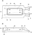
ミキシングタンク30の平面図を図2(a)に示し、図2(a)のX−X線断面図を図2(b)に示す。ミキシングタンク30は、ミキシング容器本体85を有しており、ミキシング容器本体85の内部には、1個の混合室80と、複数の導入側気体流路51、52と、気体流路42、43とが設けられている。ここでは、導入側気体流路51、52と気体流路42、43とがそれぞれ2本ずつ設けられている。
【0029】
各導入側気体流路51、52と各気体流路42、43とは、それぞれの一端が、ミキシング容器本体85の外部壁面に設けられた接続口33、34、接続口40、41となり、それぞれの他端が開口63、64、開口61、62となっており、ともに混合室80の内部と、ミキシング容器本体85の外部とを接続している。
【0030】
このうち、気体流路42、43側の接続口40、41は、後述するシャワープレート60の貫通孔50に直結されている。
シャワープレート60は、開口を有する容器状に形成され、開口が鉛直下方を向くように真空槽2の天井側壁面に取り付けられた電極3と、該電極3の開口を蓋するように真空槽2の内部側に配置された板5とを有しており、板5と電極3との間には、ガス貯留室24が形成されている。板5には複数の孔6が設けられており、ガス貯留室24の内部は、これらの孔6を介して真空槽2内に通じている。
【0031】
電極3は、本発明のシャワープレート容器本体の一例を構成しており、その上部には、ガス貯留室24に通じる貫通孔50が設けられ、上述したミキシングタンク30の気体流路42、43側の接続口40、41と直結されている。このため、混合室80の開口61、62と貫通孔50との距離は気体流路42、43の長さと一致している。ここでは気体流路42、43の長さを80mmとしている。
他方、導入側気体流路51、52側の接続口33、34は、後述するガス導入管31、32の一端に接続されている。
【0032】
真空槽2の外部には、ガス導入管31、32、マスフロコントローラ22、27、配管36、37、ガス供給源21及びガスボンベ26が設けられており、ミキシングタンク30の導入側気体流路51、52側の接続口33、34は、ガス導入管31、32の一端に接続されており、各ガス導入管31、32の他端はマスフロコントローラ22、27の一端にそれぞれ接続されている。マスフロコントローラ22、27の他端は配管36、37の一端にそれぞれ接続されており、配管36、37の他端はそれぞれガス供給源21とガスボンベ26とに接続されている。ガス供給源21は、その内部で液状のTEOSを気化した後に、気化されたTEOSガスのみを外部に供給することができるように構成されている。他方、ガスボンベ26には、O2ガスが充填されている。
【0033】
真空槽2の内部底面側には、板5と平行になるように下部電極3が配置されている。下部電極3は接地され、電極4は真空槽2外に設けられた高周波電源9に接続されており、高周波電源9から高周波電力を供給すると、下部電極3と電極4との間に放電を生じさせ、プラズマを発生させることができるように構成されている。
【0034】
上述の成膜装置1を用いて、TEOS/O2系プラズマCVD法で、複数のガラス基板の表面にSiO2膜を成膜するには、まず、真空槽2の内部を真空排気系8で所定真空度まで真空排気し、その所定真空度を維持した状態で、予め所定温度まで昇温された未処理の基板10を真空槽2内に搬入し、下部電極3上に載置させる。
【0035】
ガス供給源21、ガスボンベ26にそれぞれ接続された配管36、37には、それぞれ図示しないバルブが設けられており、基板10が下部電極3上に載置された状態で、各バルブを開くと、ガス供給源21とガスボンベ26内のTEOSガスとO2ガスとが配管36、37に供給され、マスフロコントローラ22、27でそれぞれの流量が調整されながら各ガス導入管31、32に供給される。
【0036】
各ガス導入管31、32に供給されたTEOSガスとO2ガスとは、ミキシングタンク30の各導入側気体流路51、52側の接続口33、34から、導入側気体流路51、52を介して混合室80内に導入される。
【0037】
TEOSガスとO2ガスとは混合室80内で混合され、それらの混合ガスは開口61、62から気体流路42、43へと供給された後、気体流路42、43側の接続口40、41を介して貫通孔50へと導入される。
【0038】
このとき、貫通孔50と、気体流路42、43側の接続口40、41とは直結されているので、混合ガスは、この間での圧力損失がほとんど無い状態で、貫通孔50からガス貯留室24内へと導入される。
【0039】
ガス貯留室24内に導入されたTEOSガスとO2ガスとの混合ガスは、板5に設けられた孔6から真空槽2内へと噴出され、板5の鉛直下方に配置され、下部電極3上に載置された基板10の表面へと吹き付けられる。
【0040】
この状態で、基板10を加熱して所定温度を維持させながら、高周波電源9から電極4に高周波電力を供給し、電極3、4間に放電を生じさせ、プラズマを発生させると、プラズマで原料ガスが分解されて基板10の表面で気相成長し、基板10の表面にSiO2膜が成膜される。このSiO2膜は、TEOSガスとキャリアガスとを混合していないため、その膜質が良好になっている。
【0041】
本実施形態の成膜装置1では、上述したように気体流路42、43側の接続口40、41と、電極4の貫通孔50とが直結されているので、ミキシングタンク30の気体流路42とシャワープレート60の貫通孔50との間における圧力損失がほとんどない。
【0042】
このため、かかる圧力損失分だけミキシングタンク30の混合室80の内部圧力が上昇することがないので、TEOSガスの流量を調整するマスフロコントローラ22の両端の圧力差を、十分に高くすることができる。
【0043】
従って、TEOSガスは、流量が安定した状態でマスフロコントローラ22からガス貯留室内24に供給されるので、ガス貯留室24内のTEOSガスとO2ガスとの混合ガスの状態は従来に比して安定になり、その結果、成膜されたSiO2膜の膜厚が従来に比して均一になり、膜厚の再現性が従来に比して高くなる。
【0044】
なお、本実施形態では、原料ガスとして、TEOSガスとO2ガスの混合ガスを用いたが、本発明はこれに限らず、TEOSガスに代えてTRIES(トリエトキシシラン)ガスを用いてもよいし、O2ガスに代えて亜酸化窒素ガスを用いてもよい。
【0045】
また、本実施形態では、気体流路42、43の長さを80mm程度としているが、本発明はこれに限らず、例えば300mm以下の範囲であればよい。
さらに、本実施形態では、導入側気体流路51、52と気体流路42、43をそれぞれ2本ずつ設けているが、本発明はこれに限らず、導入側気体流路は複数本設けられていればよく、例えば3本以上設けられていてもよい。他方、気体流路は1本だけ設けられていてもよく、あるいは3本以上設けられていてもよい。
【0046】
また、本実施形態では、TEOS/O2系プラズマCVD法を用いる成膜装置について説明しているが、本発明はこれに限らず、二種類以上の原料ガスをミキシングタンク30で混合した後にシャワープレート60から真空槽2内に噴出させるプラズマCVD法を実施することも可能である。
【0047】
さらに、本実施形態では、シャワープレート容器本体として高周波電圧が印加可能な電極4を用いているが、本発明はこれに限られるものではなく、シャワープレート容器本体に電圧が印加されない構成としてもよい。
また、本実施形態では、真空処理装置としてプラズマCVD装置について説明しているが、本発明の真空処理装置はこれに限られるものではない。
【0048】
【発明の効果】
薄膜の膜厚のばらつきが少なくなり、膜厚の再現性が高くなる。
【図面の簡単な説明】
【図1】本発明の一実施形態の真空処理装置を説明する断面図
【図2】(a):本発明の一実施形態のミキシングタンクを説明する平面図
(b):本発明の一実施形態のミキシングタンクを説明する断面図
【図3】従来の真空処理装置を説明する断面図
【符号の説明】
1……成膜装置(真空処理装置) 2……真空槽 4……電極(シャワープレート容器本体) 6……孔 22、27……マスフロコントローラ 24……ガス貯留室 42、43……気体流路 50……貫通孔 60……シャワープレート 80……混合室 85……ミキシング容器本体 90……ガス噴出装置[0001]
BACKGROUND OF THE INVENTION
The present invention relates to a gas ejection apparatus and a vacuum processing apparatus, and more particularly to a plasma CVD apparatus for forming an insulating film on a glass substrate and a gas ejection apparatus used for the plasma CVD apparatus in a manufacturing process of a liquid crystal display device.
[0002]
[Prior art]
In recent years, in the technical field of liquid crystal display panels, an active matrix driving method using thin film transistors is often used in order to improve display speed and display quality. In this method, since a large number of thin film transistors are formed on a glass substrate, it is necessary to form a SiO 2 insulating film with good film quality on a large area glass substrate.
[0003]
A TEOS (tetraethoxysilane) / O 2 plasma CVD method is used as a method for forming a SiO 2 film having a good film quality at a low temperature on a glass substrate having a large area.
[0004]
A
[0005]
Among the
[0006]
The other end of the
[0007]
From the
[0008]
A large number of
[0009]
A
[0010]
The
[0011]
In order to form a SiO 2 film on the surface of a glass substrate by the TEOS / O 2 plasma CVD method using the
[0012]
Next, when the flow rate of the TEOS gas and the O 2 gas in the
[0013]
In this state, high-frequency power is supplied from the high-
[0014]
When the SiO 2 film having a predetermined thickness is formed on the surface of the
[0015]
In the
[0016]
Therefore, the pressure difference between both ends of the
[0017]
Conventionally, since the
[0018]
For this reason, a sufficient pressure difference between both ends of the
As a result, there has been a problem that the film thickness of the formed thin film is not uniform or the reproducibility of the film thickness is lowered.
[0019]
[Problems to be solved by the invention]
The present invention was created to solve the above-described disadvantages of the prior art, and an object of the present invention is to provide a technique that increases the reproducibility of the film thickness when an insulating film is formed on a substrate. .
[0020]
[Means for Solving the Problems]
In order to solve the above-mentioned problem, the invention according to
According to a second aspect of the invention, a vacuum processing apparatus having a vacuum evacuable vacuum chamber, said vacuum chamber, said shower plate the claims as holes facing the
The invention according to claim 3 is the vacuum processing apparatus according to claim 2 , wherein a mass flow controller is provided outside the mixing tank, and the raw material gas is introduced into the mixing chamber via the mass flow controller. Is configured to be introduced.
Invention of
[0021]
According to the gas jetting apparatus of the present invention, the gas flow path of the mixing tank and the through hole of the shower plate are directly connected, and there is no pipe that has conventionally connected the mixing tank and the shower plate. There is almost no pressure loss between the through hole of the shower plate.
[0022]
For this reason, there is no hindrance that the internal pressure of the mixing tank increases by the amount of such pressure loss, so TEOS gas and O 2 gas are introduced into each introduction side gas flow path of the mixing tank via the mass flow controller. In such a case, it is possible to ensure a sufficient pressure difference between both ends of the mass flow controller that is connected to the mixing tank and adjusts the flow rate of the TEOS gas.
[0023]
Accordingly, since the TEOS gas flows through the mass flow controller in a stable state and is supplied into the gas storage chamber, the state of the mixed gas of the TEOS gas and the O 2 gas in the gas storage chamber becomes uniform as compared with the conventional case. The mixed gas can be ejected in a uniform state.
[0024]
Further, according to the vacuum processing apparatus of the present invention, since the gas ejection apparatus of the present invention is provided on one wall surface of the vacuum chamber, for example, a mixed gas of TEOS gas and O 2 gas is used as a source gas in the vacuum chamber. When using a plasma CVD method to form a thin film on the substrate surface, the state of the mixed gas of TEOS gas and O 2 gas in the gas storage chamber becomes uniform as compared with the conventional case. The thickness of the thin film thus made becomes uniform as compared with the prior art, and the reproducibility of the film thickness becomes higher than before.
[0025]
DETAILED DESCRIPTION OF THE INVENTION
Embodiments of the present invention will be described below with reference to the drawings.
[0026]
The
[0027]
A
[0028]
A plan view of the mixing
[0029]
One end of each of the introduction-side
[0030]
Among these, the
The
[0031]
The electrode 3 constitutes an example of the shower plate container main body of the present invention, and a through
On the other hand, the
[0032]
Outside the vacuum chamber 2,
[0033]
A lower electrode 3 is disposed on the inner bottom surface side of the vacuum chamber 2 so as to be parallel to the
[0034]
In order to form a SiO 2 film on the surfaces of a plurality of glass substrates by the TEOS / O 2 plasma CVD method using the
[0035]
The
[0036]
The TEOS gas and the O 2 gas supplied to the
[0037]
The TEOS gas and the O 2 gas are mixed in the mixing
[0038]
At this time, since the through
[0039]
A mixed gas of TEOS gas and O 2 gas introduced into the
[0040]
In this state, while the
[0041]
In the
[0042]
For this reason, since the internal pressure of the mixing
[0043]
Therefore, since the TEOS gas is supplied from the
[0044]
In the present embodiment, a mixed gas of TEOS gas and O 2 gas is used as the source gas. However, the present invention is not limited to this, and TRIE (triethoxysilane) gas may be used instead of the TEOS gas. However, nitrous oxide gas may be used instead of O 2 gas.
[0045]
Moreover, in this embodiment, although the length of the
Furthermore, in the present embodiment, two introduction-
[0046]
In this embodiment, the film forming apparatus using the TEOS / O 2 plasma CVD method is described. However, the present invention is not limited to this, and the shower is performed after mixing two or more kinds of source gases in the
[0047]
Furthermore, in this embodiment, the
In this embodiment, a plasma CVD apparatus is described as the vacuum processing apparatus, but the vacuum processing apparatus of the present invention is not limited to this.
[0048]
【The invention's effect】
The variation in the thickness of the thin film is reduced, and the reproducibility of the thickness is increased.
[Brief description of the drawings]
FIG. 1 is a cross-sectional view illustrating a vacuum processing apparatus according to an embodiment of the present invention. FIG. 2A is a plan view illustrating a mixing tank according to an embodiment of the present invention.
(b): Cross-sectional view for explaining a mixing tank according to an embodiment of the present invention [FIG. 3] Cross-sectional view for explaining a conventional vacuum processing apparatus [Explanation of symbols]
DESCRIPTION OF
Claims (4)
ミキシング容器本体を備え、該ミキシング容器本体内部には混合室が設けられ、該混合室に一端が接続され、他端が前記ミキシング容器本体に設けられた開口となる気体流路が前記ミキシング容器本体内部に設けられたミキシングタンクとを有し、
前記シャワープレート容器本体には前記ガス貯留室に通じ、前記ミキシング容器本体の開口と接続される貫通孔が設けられ、
前記混合室内で混合されたガスが、前記気体流路を通って前記貫通孔から前記ガス貯留室に導入された後、前記孔から吹き出されるように構成されたガス噴出装置であって、
前記貫通孔と、前記気体流路の開口とが直結され、
前記気体流路の長さは、300mm以下であるように構成されたことを特徴とするガス噴出装置。A shower plate container body, a gas storage chamber is provided inside the shower plate container body, and a shower plate in which a hole communicating with the gas storage chamber is formed in the shower plate container body;
A mixing container body is provided, a mixing chamber is provided inside the mixing container body, one end of the mixing chamber is connected to the mixing container body, and the other end is an opening provided in the mixing container body. A mixing tank provided inside,
The shower plate container main body is provided with a through hole that communicates with the gas storage chamber and is connected to the opening of the mixing container main body.
A gas jetting device configured to blow gas from the hole after the gas mixed in the mixing chamber is introduced from the through hole into the gas storage chamber through the gas flow path,
The through hole and the opening of the gas channel are directly connected ,
A gas ejection device characterized in that the length of the gas flow path is configured to be 300 mm or less .
前記真空槽には、前記シャワープレートの前記孔が前記真空槽内に面するように請求項1記載のガス噴出装置が設けられ、前記孔から、前記混合室内で混合されたガスが前記真空槽内に吹き出されるように構成されたことを特徴とする真空処理装置。It has a vacuum chamber that can be evacuated,
Wherein the vacuum chamber, the shower plate of the hole gas ejection device according to claim 1 Symbol placement to face the vacuum chamber is provided from the holes, mixed gas the vacuum in the mixing chamber A vacuum processing apparatus configured to be blown into a tank.
Priority Applications (1)
| Application Number | Priority Date | Filing Date | Title |
|---|---|---|---|
| JP2000153942A JP4570732B2 (en) | 2000-05-25 | 2000-05-25 | Gas ejection device and vacuum processing device |
Applications Claiming Priority (1)
| Application Number | Priority Date | Filing Date | Title |
|---|---|---|---|
| JP2000153942A JP4570732B2 (en) | 2000-05-25 | 2000-05-25 | Gas ejection device and vacuum processing device |
Publications (3)
| Publication Number | Publication Date |
|---|---|
| JP2001335941A JP2001335941A (en) | 2001-12-07 |
| JP2001335941A5 JP2001335941A5 (en) | 2007-04-19 |
| JP4570732B2 true JP4570732B2 (en) | 2010-10-27 |
Family
ID=18659113
Family Applications (1)
| Application Number | Title | Priority Date | Filing Date |
|---|---|---|---|
| JP2000153942A Expired - Lifetime JP4570732B2 (en) | 2000-05-25 | 2000-05-25 | Gas ejection device and vacuum processing device |
Country Status (1)
| Country | Link |
|---|---|
| JP (1) | JP4570732B2 (en) |
Families Citing this family (3)
| Publication number | Priority date | Publication date | Assignee | Title |
|---|---|---|---|---|
| JP4219702B2 (en) | 2003-02-06 | 2009-02-04 | 東京エレクトロン株式会社 | Decompression processing equipment |
| JP4680619B2 (en) * | 2005-02-09 | 2011-05-11 | 株式会社アルバック | Plasma deposition system |
| JP6216483B2 (en) | 2015-10-06 | 2017-10-18 | 株式会社アルバック | Mixer, vacuum processing equipment |
Citations (4)
| Publication number | Priority date | Publication date | Assignee | Title |
|---|---|---|---|---|
| JPH02205681A (en) * | 1989-02-06 | 1990-08-15 | Nec Corp | Chemical vapor growth device |
| JPH06151336A (en) * | 1992-11-04 | 1994-05-31 | Hitachi Electron Eng Co Ltd | Plasma cvd apparatus |
| JPH0794487A (en) * | 1993-09-20 | 1995-04-07 | Tokyo Electron Ltd | Treating apparatus and cleaning method thereof |
| JPH09143737A (en) * | 1995-11-22 | 1997-06-03 | Tokyo Electron Ltd | Film forming apparatus |
-
2000
- 2000-05-25 JP JP2000153942A patent/JP4570732B2/en not_active Expired - Lifetime
Patent Citations (4)
| Publication number | Priority date | Publication date | Assignee | Title |
|---|---|---|---|---|
| JPH02205681A (en) * | 1989-02-06 | 1990-08-15 | Nec Corp | Chemical vapor growth device |
| JPH06151336A (en) * | 1992-11-04 | 1994-05-31 | Hitachi Electron Eng Co Ltd | Plasma cvd apparatus |
| JPH0794487A (en) * | 1993-09-20 | 1995-04-07 | Tokyo Electron Ltd | Treating apparatus and cleaning method thereof |
| JPH09143737A (en) * | 1995-11-22 | 1997-06-03 | Tokyo Electron Ltd | Film forming apparatus |
Also Published As
| Publication number | Publication date |
|---|---|
| JP2001335941A (en) | 2001-12-07 |
Similar Documents
| Publication | Publication Date | Title |
|---|---|---|
| US5863338A (en) | Apparatus and method for forming thin film | |
| US6015591A (en) | Deposition method | |
| KR101047249B1 (en) | Method and apparatus for enhancing uniformity of large area substrates | |
| JP4335438B2 (en) | Process chamber lid assembly using asymmetric flow geometry | |
| KR100728401B1 (en) | Shower head and film-forming device using the same | |
| US7510624B2 (en) | Self-cooling gas delivery apparatus under high vacuum for high density plasma applications | |
| US20080283086A1 (en) | Substrate processing apparatus and cleaning method therefor | |
| US20050087134A1 (en) | Methods, systems, and apparatus for uniform chemical-vapor depositions | |
| US20060127068A1 (en) | Method and apparatus for silicon oxide deposition on large area substrates | |
| KR20060007375A (en) | Plasma processing device | |
| US9546422B2 (en) | Semiconductor device manufacturing method and substrate processing method including a cleaning method | |
| KR101538372B1 (en) | atomic layer deposition apparatus | |
| US5387289A (en) | Film uniformity by selective pressure gradient control | |
| JP4570732B2 (en) | Gas ejection device and vacuum processing device | |
| JP2726005B2 (en) | Film forming apparatus and film forming method | |
| JP2000311862A (en) | Substrate treating system | |
| KR20100071604A (en) | Apparatus for high density plasma chemical vapor deposition with nozzle capable of controlling spray angle | |
| JP3485505B2 (en) | Processing equipment | |
| KR20200021404A (en) | Coating material for processing chambers | |
| JP2010272551A (en) | Substrate treating device, and method of treating substrate | |
| CN220450288U (en) | Film processing apparatus | |
| KR20010104572A (en) | A chemical vapor deposition apparatus | |
| JPH09223672A (en) | Method and device for plasma treatment | |
| JPH03151629A (en) | Manufacturing equipment for semiconductor thin film and manufacture of semiconductor multilayer thin film | |
| JP2508717Y2 (en) | Mixing chamber for gas introduction in film forming equipment |
Legal Events
| Date | Code | Title | Description |
|---|---|---|---|
| A521 | Written amendment |
Free format text: JAPANESE INTERMEDIATE CODE: A821 Effective date: 20070306 Free format text: JAPANESE INTERMEDIATE CODE: A523 Effective date: 20070306 |
|
| A621 | Written request for application examination |
Free format text: JAPANESE INTERMEDIATE CODE: A621 Effective date: 20070306 |
|
| A977 | Report on retrieval |
Free format text: JAPANESE INTERMEDIATE CODE: A971007 Effective date: 20090331 |
|
| A131 | Notification of reasons for refusal |
Free format text: JAPANESE INTERMEDIATE CODE: A131 Effective date: 20100420 |
|
| A521 | Written amendment |
Free format text: JAPANESE INTERMEDIATE CODE: A821 Effective date: 20100611 Free format text: JAPANESE INTERMEDIATE CODE: A523 Effective date: 20100611 |
|
| TRDD | Decision of grant or rejection written | ||
| A01 | Written decision to grant a patent or to grant a registration (utility model) |
Free format text: JAPANESE INTERMEDIATE CODE: A01 Effective date: 20100810 |
|
| A01 | Written decision to grant a patent or to grant a registration (utility model) |
Free format text: JAPANESE INTERMEDIATE CODE: A01 |
|
| A61 | First payment of annual fees (during grant procedure) |
Free format text: JAPANESE INTERMEDIATE CODE: A61 Effective date: 20100811 |
|
| FPAY | Renewal fee payment (event date is renewal date of database) |
Free format text: PAYMENT UNTIL: 20130820 Year of fee payment: 3 |
|
| R150 | Certificate of patent or registration of utility model |
Ref document number: 4570732 Country of ref document: JP Free format text: JAPANESE INTERMEDIATE CODE: R150 Free format text: JAPANESE INTERMEDIATE CODE: R150 |
|
| R250 | Receipt of annual fees |
Free format text: JAPANESE INTERMEDIATE CODE: R250 |
|
| R250 | Receipt of annual fees |
Free format text: JAPANESE INTERMEDIATE CODE: R250 |
|
| R250 | Receipt of annual fees |
Free format text: JAPANESE INTERMEDIATE CODE: R250 |
|
| R250 | Receipt of annual fees |
Free format text: JAPANESE INTERMEDIATE CODE: R250 |
|
| R250 | Receipt of annual fees |
Free format text: JAPANESE INTERMEDIATE CODE: R250 |
|
| EXPY | Cancellation because of completion of term |