JP4567857B2 - Unit building - Google Patents
Unit building Download PDFInfo
- Publication number
- JP4567857B2 JP4567857B2 JP2000275341A JP2000275341A JP4567857B2 JP 4567857 B2 JP4567857 B2 JP 4567857B2 JP 2000275341 A JP2000275341 A JP 2000275341A JP 2000275341 A JP2000275341 A JP 2000275341A JP 4567857 B2 JP4567857 B2 JP 4567857B2
- Authority
- JP
- Japan
- Prior art keywords
- unit
- building
- floor
- columns
- joined
- Prior art date
- Legal status (The legal status is an assumption and is not a legal conclusion. Google has not performed a legal analysis and makes no representation as to the accuracy of the status listed.)
- Expired - Fee Related
Links
Images


Landscapes
- Conveying And Assembling Of Building Elements In Situ (AREA)
- Joining Of Building Structures In Genera (AREA)
Description
【0001】
【発明の属する技術分野】
本発明は、上下階で積層配置され、平面視で同一位置に柱が配設された一対の建物ユニットを含むユニット式建物に関する。
【0002】
【背景技術】
従来より、工場で製造した直方体状の建物ユニットを、建築現場で複数組み合わせて建築されるユニット式建物が利用されている。
建物ユニットは、四隅に立設される柱と、これらの柱の上端間、下端間を連結する梁とを備えた直方体状のフレームを有し、工場でこのフレームに天井面材、床面材、外壁材および間仕切壁を予め取り付けておき、これを建築現場に輸送し、各建物ユニットを建築現場で組み合わせることにより、建物が建築される。
【0003】
具体的には、特許第2625317号公報に示されるように、隣接する4つの建物ユニットの柱が密集する部分において、各柱の上端面に跨るように接合プレートを設置し、隣接する4つの建物ユニットを接続するとともに、その上階側に対応配置される建物ユニットの柱を上下でボルト、ナットを用いて接合することにより組立が行われる。
このようなユニット式建物によれば、工場で建物ユニットを製造する際に、従来建築現場で行っていた作業がほとんど工場で行われることとなり、建築現場での作業が著しく軽減され、高品質の建物を短期間で建築できるという効果がある。
【0004】
上述したユニット式建物において、建物形状の複雑化に伴い、通常の建物ユニットとは平面形状の異なる異形ユニットが利用されるようになっている。この異形ユニットとしては、例えば、平面視略L字形状のL形ユニットがあり、このようなL形ユニットは、平面視で出隅部分に配設される通常の柱の他に、入隅部分にも柱が設けられている。
【0005】
そして、このような2つのL形ユニットをL字部分を向き合わせるように配置して建物1階部分を構成し、さらに2階部分に1階部分と同様のL形ユニットを積層配置することにより、外壁面の一部が他の外壁面よりも室内側に後退した凹部を有するユニット式建物を形成することができるため、設計自由度の高いユニット式建物を建築することができる、という利点がある。
【0006】
【発明が解決しようとする課題】
しかしながら、このような異形ユニットを上下階間で接合する場合、従来、異形ユニットを構成する柱のすべてを上下間で接合していたため、上下階間の建物ユニットの接合作業が、通常の建物ユニットよりも繁雑となり、建築現場における効率化が十分に図れないという問題がある。
【0007】
本発明の目的は、上下階で積層配置され、平面視で同一位置に柱が配設された一対の建物ユニットを含むユニット式建物において、建築現場における作業の効率化を図ることのできるユニット式建物を提供することにある。
【0008】
【課題を解決するための手段】
前記目的を達成するために、本発明のユニット式建物は、図面の符号を参照して説明すれば、上下階で積層配置され、平面視で同一位置に柱が配設された一対の建物ユニット33を含むユニット式建物1であって、前記建物ユニットは、上下階間で互いに接合される柱332と、上下階間で互いに接合されない柱334と、前記上下階間で互いに接合される柱の上端間および下端間をそれぞれ連結する、断面コ字状の上梁333および下梁333とを備え、前記互いに接合されない柱334は、前記上梁333および前記下梁333間に配設されており、上階側の建物ユニットの下梁333および下階側の建物ユニットの上梁333の間における前記互いに接合されない柱の配置位置に対応する位置に、上階側の柱の荷重を下階側の柱に伝達するスペーサ70が介装されており、且つ、前記上階側の建物ユニットの下梁333の内側および前記下階側の建物ユニットの上梁333の内側における前記スペーサ70に対応する位置には、断面コ字状の補強材333Aがそれぞれ接合されていることを特徴とする。ここで、上下階間で互いに接合される柱と、上下階間で互いに接合されない柱とを備えた建物ユニットとしては、上述した平面視略L字形状のL形ユニット33があり、このL形ユニットの入隅部分に配設される柱を上下階間で互いに接合されない柱とすることが考えられる。
【0009】
このような本発明によれば、互いに接合されない柱の上下間の荷重伝達をスペーサを介して行うことができるため、該柱の上下間の接合作業を省略することができ、通常の建物ユニットよりも柱の本数が多い異形ユニットであっても、すべての柱の上下間の接合をする必要がなく、上下階間の建物ユニットの連結作業の簡単化を図ることができ、建築現場における作業の効率化を図ることができる。
また、上述したL形ユニットの場合、入隅部分等に柱を設ける必要があり、建物ユニットを構成する柱の本数が多くなる傾向にあるため、本発明を採用することの有用性は高い。
【0010】
以上において、上述したL形ユニットのL字の入隅部分を含む側面の上端および/または下端部分には、水平方向に突設され、屋外床面を構成する水平支持部材33C、33Dが設けられているのが好ましい。
このようにL形ユニットが水平支持部材を備えている場合、該水平支持部材をL形ユニットで支持するために、L形ユニットの入隅部分に柱を設置することが必須となるので、上述したスペーサを介して支持構造を採用することの有用性が一層高まる。
【0011】
また、上述した建物ユニットが、上下階間で互いに接合される柱の上端間、下端間を連結する上梁333、下梁333を備えている場合、上下階間で互いに接合されない柱は、この上梁および下梁間に設けられたいわゆる梁勝ちの構造とすることが必要である。このように梁勝ちの構造とすることにより、上下階間で互いに接合される柱の上端間、下端間を上梁、下梁で連結することにより、概ねの建物ユニットの立体構造を構築することができ、必要に応じて、上下階間で互いに接合されない柱を上梁、下梁間に接合すればよいから、工場における建物ユニットの製造作業の効率化を図ることができる。
【0012】
さらに、上述したスペーサの厚さ寸法Hは、互いに上下間で接合される柱の接続部分の上下方向寸法よりも大きな寸法とされているのが好ましい。
このようにスペーサの厚さ寸法が柱の接続部分の上下方向寸法よりも大きな寸法とされることにより、上下間の柱を接合すると、スペーサが上階側の異形ユニットの下梁と、下階側の異形ユニットの上梁とによって狭持されることとなるので、上階側の接合されない柱が支持する荷重を、下階側の接合されない柱にスペーサを介して確実に伝達することができる。
【0013】
【発明の実施の形態】
以下、本発明の実施の一形態を図面に基づいて説明する。
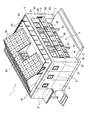
図1には、本発明の実施形態に係るユニット式建物1が示され、このユニット式建物1は、コンクリート製の基礎2上に設置される建物本体3と、この建物本体3の上部に形成される屋根4とを備えている。
【0014】
前記屋根4は、屋上を物干し等の空間として利用できる陸屋根として構成され、後述する建物ユニット31、33、35の平面形状を有し、平板状の複数の屋根パネル41を配列して構成される。屋根パネル41は、図示を略したが、パネル形状に応じて鋼材を組み合わせたフレームと、このフレーム上に取り付けられるALC等の面材とを備える。
【0015】
この屋根4の中央部分には、傾斜面上に複数の太陽電池パネル42が配列されている。この太陽電池パネル42は、図示しない立体構造の鋼製フレーム上に、野地板、防水シート、さらに傾斜面に沿った複数本のレールが取り付けられ、複数本のレールに跨るように取り付けられている。
また、この太陽電池パネル42が取り付けられた傾斜面の下部空間は、収納空間として利用することができるとともに、屋根4の陸屋根部分に昇るためのペントハウスとしての役割も有し、扉43から出入り可能な陸屋根部分の外周端縁には、手摺44が設けられている。
【0016】
前記建物本体3は、一部の外壁面3Bが他の外壁面3Aよりも室内側に後退した凹部5を有し、平面視略凹形状の居室空間を有するものである。
この凹部5の1階部分には、基礎2と連続するコンクリート製の犬走21が形成され、2階部分には、屋外床面としてのバルコニ床面6が形成されている。
犬走21上には、所定のピッチでポーチ柱51が設けられ、各ポーチ柱51は、2階部分のバルコニ床面6の先端部分を支承している。
【0017】
バルコニ床面6の屋外側先端部分6Aは、他の外壁面3Aよりも若干外側に突出し、バルコニ床面6の外周端縁に沿って手摺61が設けられている。
凹部5の上部は、外壁面3Aに沿って端縁が形成された屋根4によって覆われていて、バルコニ床面6上にも、1階部分のポーチ柱51と同様のピッチでポーチ柱62が設けられ、各ポーチ柱62は、屋根4の先端部分を支承している。
【0018】
このような形状の建物本体3は、直方体状の通常の建物ユニット31と、凹部5を構成する平面視略L字形状のL形ユニット33、および建物ユニット31とは、短辺方向の寸法が異なるL形ユニット33とは異なる形状の異形ユニット35とを立体的に組み合わせることにより構成される。
建物ユニット31は、図2に示すように、直方体状のフレーム311を有し、このフレーム311は、四隅に立設される柱312と、各柱312の上端間を連結する上梁313と、各柱312の下端間を連結する下梁314とを備えている。
【0019】
そして、建物ユニット31の長辺方向に延びる一対の上梁313間には、複数本の天井小梁315が架設され、天井小梁315の下面には、図示しない天井材が取り付けられる。また、建物ユニット31の長辺方向に延びる一対の下梁314間には、複数の床根太316が架設され、床根太316の上面には、図示しない床面材が敷設される。さらに、この建物ユニット31には、ユニット式建物1の間取り等に応じて、間仕切壁や外壁材が取り付けられたり、キッチン等の設備機器が取り付けられる。
【0020】
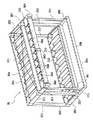
L形ユニット33は、平面長方形の1つの角隅部を矩形状に切り欠いた平面視L字形状の形を基本構成とし、図3に示すように、建物本体3の構造を負担する基部33Aと、この基部33Aの側面に突設される拡張部33Bと、L形ユニットの床部分および天井部分に水平方向に突設される床張出部33Cおよび天井張出部33Dとを備えている。
【0021】
基部33Aは、直方体状のフレーム331を有し、四隅に立設される柱332と、各柱332の上端間、下端間を連結する梁333とを備え、拡張部33Bが接続される基部33Aの中間部分には、上下の梁333間に跨るように、すなわち梁333勝ちで中間柱334が設けられている。また、中間柱334が設けられる部分における一対の長辺方向の梁333間には、中間梁334Aが架設されている。そして、この基部33Aが建物本体3の構造を負担する部分であることから、柱332、334、梁333、334Aの材料としては、前記建物ユニット31の柱312、梁313、314と同様の断面形状の鋼材が採用されている。
【0022】
拡張部33Bは、基部33Aの短辺側面に沿って、長辺側面から突出するように設けられる箱状のフレーム335を有する。
このフレーム335は、基部33Aの短辺方向の梁333に沿って延びる2本の水平架設材336と、中間柱334の取り付け部分の長辺方向の梁333の側面から垂直に突出する2本の水平架設材337と、水平架設材336、337の先端部分を連結する2本の水平架設材338と、2本の水平架設材336、または2本の水平架設材337を上下に連結する垂直架設材339とを備えている。
【0023】
ここで、拡張部33Bの内部空間は、基部33A内に形成される居室空間と連続する空間として利用されることから、水平架設材336、337、338の材料としては、基部33Aの梁333と同様の高さ寸法の鋼材が採用される。
一方、拡張部33Bが建物本体3の基本的構造を負担するものではないことから、垂直架設材339の材料としては、基部33Aの柱332よりも断面形状の小さな鋼材が採用され、この鋼材の断面形状は、上下に連なる拡張部33Bの荷重に応じて設定される。
【0024】
床張出部33Cおよび天井張出部33Dは、バルコニ床面6を構成する水平支持部材として構成され、L形ユニット33が上下に組み合わされることにより、バルコニ床面6が形成される。尚、図3から判るように、床張出部33Cよりも天井張出部33Dの方が強固なフレームとして構成され、バルコニ床面6の構造上の支持は、主として天井張出部33Dが負担する。
【0025】
床張出部33Cは、拡張部33Bの側面から突出し、該拡張部33Bの水平架設材338の延出方向に沿って延びる水平枠部材340と、基部33Aの短辺方向の梁333に沿って延び、先端部分で水平枠部材340と接合される水平枠部材341とを備えた矩形枠状に構成されている。尚、水平枠部材340、341は、上述したようにバルコニ床面6の構造を主として負担するものではないので、基部33Aの梁333よりも断面形状の小さいものが採用されている。
この床張出部33Cは、L形ユニット33が1階部分で使用される場合、犬走21のコンクリート打設の際に、コンクリート内に埋設される。一方、L形ユニット33が2階部分で使用される場合、水平枠部材340、341で囲まれた部分に防水構造が形成され、バルコニ床面6の防水面とされる。
【0026】
天井張出部33Dは、床張出部33Cの平面形状と略同様の平面形状に構成され、床張出部33Cと同様に、外周枠を構成する水平枠部材342、343を備え、その内側には、水平枠部材343と、拡張部33Bの水平架設材337との間に中間架設材344が設けられている。
そして、この中間架設材344および水平枠部材342の間には、断面コ字形状の鋼製小梁345が複数本架設されている。一方、中間架設材344および基部33Aの間の空間は、図示を略したが、凹部5の側面に形成された開口部を覆う雨戸としてのシャッタが収納されるシャッタケースとしての役割を有する。
【0027】
また、水平枠部材342の外側側面には、バルコニ床面6の屋外側先端部分6Aを構成する片持ち支持構造のバルコニ拡張部を支持するためのブラケット346が複数設けられている。
このような天井張出部33Dは、バルコニ床面6を構造的に支持しなければならないので、水平枠部材342、343の材料としては、基部33Aの梁333と同様の断面形状の鋼材が用いられる。
中間架設材344の材料としては、バルコニ床面6の支持構造に寄与し、かつシャッタを含むシャッタケースを支持できる鋼材が用いられる。
鋼製小梁345の断面形状、およびその本数は、先端に取り付けられるキャンティ構造のバルコニ拡張部の重量に基づいて適宜設定される。
【0028】
上述した床張出部33Cの水平枠部材340と、天井張出部33Dの水平枠部材343との間には、上下に延びる垂直部材347が設けられ、この垂直部材347は、隣接する異形ユニット35に設けられる垂直部材361(後述)と組み合わされて凹部5の先端部分に立設されるポーチ柱51を構成する。
尚、バルコニ床面6や屋根4の被覆部分の構造負担を、主としてL形ユニット33の天井張出部33Dで行うことから、この垂直部材347は、バルコニ床面6等を支承する補足的な部材であり、従って、その断面形状も基部33Aを構成する柱312の断面形状よりも小さなものとなっている。
【0029】
このようなL形ユニット33の工場でのフレームの組立は、まず基部33Aの柱332および梁333を溶接接合してフレーム331の外形を構成した後、中間柱334を上下の梁333間に架設して溶接接合し、次に、基部33Aの側面に拡張部33Bを溶接等により接合し、最後に床張出部33Cおよび天井張出部33Dを取り付けることにより行われる。
そして、L形ユニット33のフレーム部分が組み立てられたら、このフレームに床面材、天井面材等を取り付けるとともに、シャッタケース等の必要な設備部材を取り付ける。
【0030】
異形ユニット35は、上述したL形ユニット33の基部33Aの短辺方向寸法と同じ寸法の短辺方向寸法を有する基部35Aと、この基部35Aの凹部5に臨む側面に突設される床張出部35B、および天井張出部35Cとを備えている。
基部35Aは、柱352、梁353を組み合わせた直方体状のフレーム351を有し、柱352、梁353の材料としては、L形ユニット33の基部33Aと同様の柱、梁部材が採用される。
【0031】
床張出部35B、および天井張出部35Cも、L形ユニット33の床張出部33C、天井張出部35Dと略同様の構造および材料で構成され、床張出部35Bは、水平枠部材354、355を備え、天井張出部35Cは、水平枠部材356、357、中間架設材358、鋼製小梁359、ブラケット360を備え、さらに床張出部35Bおよび天井張出部35Cの間には、幅方向端部に2本の垂直部材361が架設され、この垂直部材361も、L形ユニット33の垂直部材347と同じ断面形状とされている。尚、このような異形ユニット35の製造も、L形ユニット33と同様に、基部35Aを組み立てた後に、床張出部35B、天井張出部35Cを基部35Aの側面に取り付けることにより行われる。
【0032】
次に、上述した建物ユニット31、33、35の建築現場における接合手順について説明する。
トラック等の輸送手段で輸送された建物ユニット31、33、35は、揚重機等で基礎2上に設置される。
建物ユニット31、33、35が基礎2上に設置されたら、隣接する建物ユニット31、33、35同士を接続し、さらに上階側の建物ユニット31、33、35を載置し、上下左右の建物ユニット31、33、35の接合固定を行うが、例えば、平面的に配置される4つの建物ユニット31を上下階間で接合する場合、次のような接続構造が採用される。
【0033】
すなわち、図5に示すように、隣接する4つの建物ユニット31の柱312の上面には、ピン317が立設されるとともに、上下階連結用のボルト318、ナット319を取り付けるための孔320が形成されている。同様に、柱312の下端面にも、ボルト318、ナット319を取り付けるための孔320が形成されている。
4つの建物ユニット31の柱312が4本密集する部分には、接合プレート321がこれら4本の柱312の上面に跨るように配置される。尚、この接合プレート321には、各柱312の上面に立設されるピン317が挿入される孔321Aと、上述した上下階連結用のボルト318、ナット319を取り付けるための孔321Bが複数形成されている。
【0034】
一方、隣接する2つの建物ユニット31の隣接する2本の柱312が密集する部分には、接合プレート322が、これら2本の柱312を跨るように配置され、上記と同様に、この接合プレート322にも、ピン317が挿入される孔322Aと、ボルト318、ナット319を取り付けるための孔322Bが複数形成されている。
【0035】
前記接合プレート321、322を用いた建物ユニット31同士の接合固定は、まず、隣接する建物ユニット31間の相対位置を調整しながら、柱312の上面に立設されるピン317を、接合プレート321、322のピン挿入用の孔321A、322Aに挿入し、1階部分の隣接する建物ユニット31の密集した柱312を接合プレート321、322で接続する。これにより、1階部分の建物ユニット31の相対位置が決定する。
【0036】
次に、2階部分の建物ユニット31を、1階部分の各建物ユニット31の配置に応じて載置する。尚、図示を略したが、建物ユニット31の柱312の下面には、孔が形成されていて、下階側の建物ユニット31の柱312の上面に立設されたピン317は、接合プレート321、322を介してこの孔に挿入されることにより、上下階間の建物ユニット31の相対位置が決定する。
【0037】
最後に、ボルト318を上階側の建物ユニット31の柱312の下面に形成された孔320に挿入し、接合プレート321、322の孔321B、322Bを介して、下階側の建物ユニット31の柱312の上面の孔320からボルト318の先端部分を突出させ、このボルト318の先端部分と、ナット319を螺合固定することにより、上下階に配置される4つの建物ユニット31の接合固定を行う。
【0038】
前記L形ユニット33の基部33Aの四隅に立設される柱332と他の建物ユニット31の柱312との接合固定、異形ユニット35の基部35Aの四隅に立設される柱352と他の建物ユニット31、33の柱312、332との接合固定も、上述と同様に、接合プレート321、322、ボルト318、ナット319によって行われるが、L形ユニット33の基部33Aの中間柱334の上下間の接続構造、および拡張部33Bの垂直架設材339の上下間の接続構造は、これと相違する。
【0039】
すなわち、図6に示すように、下階側のL形ユニット33の中間柱334が接合された上梁333の上面と、上階側のL形ユニット33の中間柱334が接続された下梁333の下面との間には、金属製のスペーサ70が介装されているが、上下間を接合固定するボルト、ナット等の締結部材は設けられていない。スペーサ70の厚さ寸法Hは、上述した接合プレート321、322を介して接続された上下方向寸法、すなわち接合プレート321、322の厚さ寸法よりも若干大きくなっている。
【0040】
そして、L形ユニット33の上下の柱332同士を、接合プレート321、322を介して接続し、ボルト318、ナット319で締結すると、スペーサ70には、上下の梁333によって圧縮方向の力が作用し、これらの梁333に狭持固定されることとなる。
【0041】
尚、図6から判るように、スペーサ70が介装される部分の断面コ字状の上下の梁333には、内側に断面コ字状の補強材333Aが溶接により接合されていて、上階側の中間柱334に作用する荷重は、上階側の梁333および補強材333Aの接合構造によって、左右均等にスペーサに作用し、さらに、下階側の梁333および補強材333Aの接合構造によって左右均等に下階側の中間柱334に伝達される。
【0042】
また、図6では図示を略したが、基部33Aの中間柱334が架設される部分には、中間梁334Aが架設されているため(図3参照)、中間柱334による鉛直方向荷重によって梁333にねじれが生じることもない。
以上のようなスペーサ70を介した接続構造は、上階側のL形ユニット33の上面に載置される屋根パネル41との間でも行われ、中間柱334と屋根パネル41との間の接合固定も行われない。
【0043】
一方、図示を略したが、L形ユニット33の拡張部33Bを構成する垂直架設材339は、1階部分で基礎2とアンカーボルトによって接続され、2階部分の垂直架設材339は、この1階部分の垂直架設材339の上面でボルトナットによる接合のみが行われ、建物本体3に作用する水平方向の力に抵抗する接合プレートのようなものは介装されていない。
【0044】
このようなL形ユニット33の上下の接続構造は、構造計算上、次のように取り扱われる。すなわち、図7の模式図に示されるように、基部33Aの四隅部分に配置される柱332の上下の接合構造は、接合プレート321、322(図5参照)、ボルト318、ナット319により強固に接合されているため、剛接点の構造Sとして取り扱われる。一方、中間柱334の上下の接続構造は、スペーサ70を介装したのみであるから、単に屋根4の荷重を支持するだけのピン節点の構造Pとして取り扱われる。さらに、垂直架設材339の上下の接続構造は、ボルト、ナット339Aのみで接合されているだけで、水平力を拘束するプレートが介装されていないので、この部分もピン節点の構造Pとして取り扱われる。
【0045】
このような本実施形態によれば、次のような効果がある。
(1) 互いに接合されない中間柱334の上下間の荷重伝達をスペーサ70を介して行うことができるため、中間柱334の上下間の接合作業を省略することができ、L形ユニット33の柱332、334のように、通常の建物ユニット31の柱312の本数が多い、異形ユニットであっても、上下階間のL形ユニット33の連結作業の簡単化を図ることができ、建築現場における作業の効率化を図ることができる。特に、L形ユニット33のように入隅部分に柱334を設ける必要のある異形ユニットに有用である。
【0046】
(2) L形ユニット33が入隅部分に水平支持部材となる床張出部33Cおよび天井張出部33Dを備えているので、これらの張出部33C、33Dを基部33Aで支持するには、入隅部分に設けられる中間柱334が必須の構成となり、スペーサ70を介装した荷重支持構造を採用することの有用性が一層高まる。
(3) L形ユニット33の基部33Aの中間柱334が梁333間に架設されたいわゆる梁勝ちの構造とされているため、概ねのL形ユニット33の基部33Aの構造を組み立てた後、必要に応じて中間柱334を梁333間に架設すればよいから、工場におけるL形ユニット33の製造作業の効率化を図ることができる。
【0047】
(4) スペーサ70の厚さ寸法Hが、図5に示される柱332の接合固定部分の上下方向寸法よりも大きな寸法とされているため、接合プレート321、322、ボルト318、ナット319によって上下の柱332を接合固定すると、梁333間に介装されたスペーサ70がこれらの梁333によって狭持されるので、上階側の中間柱334に作用する荷重を確実に下階側の中間柱334に伝達することができる。
【0048】
(5) 中間柱334が接続される梁333の内側に補強材333Aが接合されているので、中間柱334に作用する荷重をこの接合構造を介してスペーサ70に均等に作用させることができ、荷重を伝達する上で一層好ましい。
(6) 中間柱334の位置に対応して、基部33Aの長辺方向の一対の梁333間に中間梁334Aが架設されているため、中間柱334に作用した鉛直荷重によって梁333にねじれが生じることもなく、確実に上階側の中間柱334に作用する力を、下階側の中間柱334に伝達することができる。
【0049】
尚、本発明は、前述の実施形態に限定されるものではなく、以下に示すような変形をも含むものである。
前記実施形態では、L形ユニット33の中間柱334の上下の接続のみをスペーサ70を介して行っていたが、本発明はこれに限られない。すなわち、異形ユニットは、L形ユニットに限られず、他の平面形状の異形ユニットであっても、本発明を採用することができる。さらに、平面矩形状の建物ユニットであっても、間仕切設置等の関係から、中間柱を必要とするような場合であっても、本発明の接続構造を採用することができる。
【0050】
また、前記実施形態では、L形ユニット33に水平支持部材となる床張出部33C、天井張出部33Dが設けられていたが、これらの張出部33C、33Dは必ずしも設けられている必要はなく、水平支持部材が設けられていないL形ユニット33に本発明を採用してもよい。
さらに、前記実施形態では、基部33Aに1つの拡張部33Bが突設されたL形ユニット33について、入隅部分の中間柱334の荷重支持を行うために、スペーサ70を用いていたが、本発明はこれに限られない。すなわち、基部に対して、2つの拡張部が形成された平面凹形状の異形ユニットの入隅部分に配置される2本の中間柱のそれぞれの上下間の荷重支持を、前記スペーサを介して行うようにしてもよい。
【0051】
そして、前記実施形態では、L形ユニット33は、水平枠部材340および341からなる床張出部33Cが基部33Aから突設されていたが、本発明は、これに限られない。すなわち、天井張出部は形成されているが、床張出部が形成されておらず、天井張出部の下面を支持する垂直部材のみが設けられたL形ユニットに、本発明を採用してもよい。この場合、トラック等による輸送時、L形ユニットの下面に枠状の輸送治具を設け、前記垂直部材の下端をこの輸送治具で固定し、垂直部材の動きを規制するのが好ましい。
その他、本発明の実施の際の具体的な構造および形状等は、本発明の目的を達成できる範囲で他の構造等としてもよい。
【0052】
【発明の効果】
請求項1記載の発明によれば、互いに接合されない柱の上下間の荷重伝達をスペーサを介して行うことができるため、該柱の上下間の接合作業を省略することができ、通常の建物ユニットよりも柱の本数が多い異形ユニットであっても、すべての柱の上下間の接合をする必要がなく、上下階間の建物ユニットの連結作業の簡単化を図ることができ、建築現場における作業の効率化を図ることができる、という効果がある。
【0053】
請求項2記載の発明によれば、L形ユニットの場合、入隅部分等に柱を設ける必要があり、建物ユニットを構成する柱の本数が多くなる傾向にあり、本発明を採用することの有用性が高い、という効果がある。
請求項3記載の発明によれば、L形ユニットが水平支持部材を備えている場合、該水平支持部材をL形ユニットで支持するために、Lが多ユニットの入隅部分に柱を設置することが必須となるため、本発明を採用することの有用性が一層高まる、という効果がある。
【0054】
請求項4記載の発明によれば、上下階間で互いに接合されない柱が上梁および下梁間に設けられたいわゆる梁勝ちの構造とされているため、上下階間で互いに接合される柱の上端間、下端間を上梁、下梁で連結することにより、概ねの建物ユニットの立体構造を構築することができ、必要に応じて、上下階間で互いに接合されない柱を上梁、下梁間に接合すればよいから、工場における建物ユニットの製造作業の効率化を図ることができる、という効果がある。
【0055】
請求項5記載の発明によれば、スペーサの厚さ寸法が柱の接続部分の上下方向寸法よりも大きな寸法とされることにより、上下間の柱を接合すると、スペーサが上階側の異形ユニットの下梁と、下階側の異形ユニットの上梁とによって狭持されることとなるので、上階側の接合されない柱が支持する荷重を、下階側の接合されない柱にスペーサを介して確実に伝達することができる、という効果がある。
【図面の簡単な説明】
【図1】本発明の実施形態に係るユニット式建物の概要斜視図である。
【図2】前記実施形態における建物ユニットの構造を表す概要斜視図である。
【図3】前記実施形態におけるL形ユニットの構造を表す概要斜視図である。
【図4】前記実施形態における他の異形ユニットの構造を表す概要斜視図である。
【図5】前記実施形態における上下で接合される柱の接合構造を表す分解斜視図である。
【図6】前記実施形態における上下で接合されない柱の接続構造を表す分解斜視図である。
【図7】前記実施形態における上下のL形ユニット間の接続の構造計算上の取扱を説明するための模式図である。
【符号の説明】
1 ユニット式建物
33 L形ユニット(平面視で同一位置に柱が配設された建物ユニット)
33C、33D 水平支持部材
70 スペーサ
332 柱(上下階間で互いに接合される柱)
333 上梁、下梁
334 中間柱(上下階間で互いに接合されない柱)
H スペーサの厚さ寸法[0001]
BACKGROUND OF THE INVENTION
The present invention relates to a unit type building including a pair of building units that are stacked on upper and lower floors and columns are arranged at the same position in plan view.
[0002]
[Background]
Conventionally, unit type buildings constructed by combining a plurality of rectangular parallelepiped building units manufactured at a factory at a construction site have been used.
The building unit has a rectangular parallelepiped frame having columns erected at the four corners and beams connecting between the upper ends and the lower ends of these columns. The building is constructed by attaching the outer wall material and the partition wall in advance, transporting them to the construction site, and combining the building units at the construction site.
[0003]
Specifically, as shown in Japanese Patent No. 2625317, in a portion where columns of four adjacent building units are densely packed, a joining plate is installed so as to straddle the upper end surface of each column, and four adjacent buildings Assembling is performed by connecting the units and joining the pillars of the building unit arranged on the upper floor side using bolts and nuts at the top and bottom.
According to such a unit-type building, when manufacturing a building unit at a factory, most of the work conventionally performed at the construction site is performed at the factory, and the work at the construction site is remarkably reduced, and high quality The effect is that the building can be built in a short period of time.
[0004]
In the unit type building described above, a deformed unit having a planar shape different from that of a normal building unit is used as the shape of the building becomes complicated. As this deformed unit, for example, there is an L-shaped unit having a substantially L shape in a plan view, and such an L-shaped unit has a corner portion in addition to a normal column disposed in a projected corner portion in a plan view. There are also pillars.
[0005]
And by arranging such two L-shaped units so that the L-shaped parts face each other to form the first floor part of the building, and by arranging the same L-shaped unit as the first floor part on the second floor part, Since a unit type building having a recessed portion in which a part of the outer wall surface recedes on the indoor side from the other outer wall surface can be formed, there is an advantage that a unit type building with a high degree of design freedom can be constructed. is there.
[0006]
[Problems to be solved by the invention]
However, when joining such deformed units between the upper and lower floors, all of the pillars that make up the deformed unit are conventionally joined between the upper and lower floors. There is a problem that it becomes more complicated and the efficiency at the construction site cannot be sufficiently achieved.
[0007]
An object of the present invention is a unit type that can improve work efficiency at a building site in a unit type building including a pair of building units that are arranged in layers on the upper and lower floors and columns are arranged at the same position in plan view. To provide a building.
[0008]
[Means for Solving the Problems]
To achieve the above object, a unit building according to the present invention will be described with reference to the drawings. A pair of building units are arranged in a stacked manner on the upper and lower floors and columns are arranged at the same position in plan view. The building unit 1 includes a
[0009]
According to the present invention, since the load transmission between the upper and lower columns that are not joined to each other can be performed via the spacer, the joining operation between the upper and lower columns can be omitted. However, even for odd-shaped units with a large number of pillars, it is not necessary to join all the pillars between the top and bottom, simplifying the work of connecting the building units between the upper and lower floors, Efficiency can be improved.
Further, in the case of the above-described L-shaped unit, it is necessary to provide columns at the corners and the like, and the number of columns constituting the building unit tends to increase. Therefore, the utility of adopting the present invention is high.
[0010]
In the above, the upper and / or lower end portions of the side surface including the L-shaped corner portion of the L-shaped unit described above are provided with
When the L-type unit is provided with a horizontal support member in this way, in order to support the horizontal support member with the L-type unit, it is essential to install a column at the corner of the L-type unit. The usefulness of adopting the support structure through the spacer is further increased.
[0011]
In addition, when the building unit described above includes the
[0012]
Furthermore, it is preferable that the thickness dimension H of the spacer described above is larger than the vertical dimension of the connecting portions of the columns that are joined together in the vertical direction.
In this way, the thickness of the spacer is larger than the vertical dimension of the connecting portion of the column, so that when the column between the upper and lower sides is joined, the spacer is connected to the lower beam of the deformed unit on the upper floor side and the lower floor. The load supported by the non-joined pillar on the upper floor side can be reliably transmitted to the unjoined pillar on the lower floor side via the spacer. .
[0013]
DETAILED DESCRIPTION OF THE INVENTION
Hereinafter, an embodiment of the present invention will be described with reference to the drawings.
FIG. 1 shows a unit type building 1 according to an embodiment of the present invention. The unit type building 1 is formed on a building
[0014]
The roof 4 is configured as a land roof that can use the roof as a space for clothes drying, etc., has a planar shape of
[0015]
In the central part of the roof 4, a plurality of
Further, the lower space of the inclined surface to which the
[0016]
The
A
On the
[0017]
The outdoor-
The upper portion of the recess 5 is covered with a roof 4 having an edge formed along the
[0018]
The
As shown in FIG. 2, the
[0019]
A plurality of ceiling beams 315 are installed between a pair of
[0020]
The L-shaped
[0021]
The
[0022]
The
The
[0023]
Here, since the internal space of the
On the other hand, since the
[0024]
The floor projecting portion 33C and the
[0025]
The floor projecting portion 33C protrudes from the side surface of the
When the L-shaped
[0026]
The
A plurality of steel beams 345 having a U-shaped cross section are installed between the
[0027]
In addition, a plurality of
Since such a
As the material of the
The cross-sectional shape of the steel beam 345 and the number thereof are appropriately set based on the weight of the balconi expansion portion of the Chianti structure attached to the tip.
[0028]
A vertical member 347 extending vertically is provided between the
In addition, since the structural burden of the covering portion of the
[0029]
Assembling the frame at the factory of such an L-shaped
When the frame portion of the L-shaped
[0030]
The odd-shaped
The
[0031]
The
[0032]
Next, the joining procedure in the construction site of the
Building
When the
[0033]
That is, as shown in FIG. 5, a
In a portion where the four
[0034]
On the other hand, in a portion where two
[0035]
In the joining and fixing of the
[0036]
Next, the
[0037]
Finally, the
[0038]
Joining and fixing the
[0039]
That is, as shown in FIG. 6, the upper surface of the
[0040]
Then, when the upper and
[0041]
As can be seen from FIG. 6, the upper and
[0042]
Although not shown in FIG. 6, since the
The connection structure through the
[0043]
On the other hand, although not shown in the figure, the
[0044]
Such an upper and lower connection structure of the L-shaped
[0045]
According to this embodiment, there are the following effects.
(1) Since the load transmission between the upper and lower parts of the
[0046]
(2) Since the L-shaped
(3) Since the
[0047]
(4) Since the thickness dimension H of the
[0048]
(5) Since the reinforcing
(6) Since the
[0049]
In addition, this invention is not limited to the above-mentioned embodiment, The modification as shown below is also included.
In the above embodiment, only the upper and lower connections of the
[0050]
In the above embodiment, the L-shaped
Further, in the above embodiment, the
[0051]
In the above-described embodiment, the L-shaped
In addition, the specific structure, shape, and the like when implementing the present invention may be other structures as long as the object of the present invention can be achieved.
[0052]
【The invention's effect】
According to the first aspect of the present invention, since the load transmission between the upper and lower pillars that are not joined to each other can be performed via the spacer, the joining work between the upper and lower pillars can be omitted. Even if it is a deformed unit with more columns, it is not necessary to connect all the columns between the upper and lower sides, and it is possible to simplify the connection work of the building units between the upper and lower floors. There is an effect that it is possible to improve efficiency.
[0053]
According to the second aspect of the present invention, in the case of the L-shaped unit, it is necessary to provide columns at the corners and the like, and the number of columns constituting the building unit tends to increase. There is an effect that it is highly useful.
According to the third aspect of the present invention, when the L-shaped unit is provided with a horizontal support member, in order to support the horizontal support member with the L-shaped unit, L installs a pillar at the corner of the multi-unit. Therefore, there is an effect that the usefulness of adopting the present invention is further enhanced.
[0054]
According to the invention described in claim 4, since the pillars that are not joined to each other between the upper and lower floors have a so-called beam winning structure provided between the upper and lower beams, the upper ends of the pillars that are joined to each other between the upper and lower floors. By connecting the upper and lower ends with upper and lower beams, it is possible to construct a general three-dimensional structure of the building unit, and if necessary, connect columns that are not joined to each other between the upper and lower floors between the upper and lower beams. Since joining should just be carried out, there exists an effect that efficiency improvement of the manufacturing operation of the building unit in a factory can be aimed at.
[0055]
According to the fifth aspect of the present invention, when the thickness of the spacer is larger than the vertical dimension of the connecting portion of the column, when the column between the upper and lower sides is joined, the spacer is deformed on the upper floor side. Since the lower beam and the upper beam of the odd-shaped unit on the lower floor side are sandwiched, the load supported by the non-joined column on the upper floor side is applied to the unjoined column on the lower floor side via a spacer. There is an effect that it can be transmitted reliably.
[Brief description of the drawings]
FIG. 1 is a schematic perspective view of a unit building according to an embodiment of the present invention.
FIG. 2 is a schematic perspective view showing the structure of a building unit in the embodiment.
FIG. 3 is a schematic perspective view showing the structure of an L-shaped unit in the embodiment.
FIG. 4 is a schematic perspective view showing the structure of another deformed unit in the embodiment.
FIG. 5 is an exploded perspective view showing a joining structure of columns joined at the top and bottom in the embodiment.
FIG. 6 is an exploded perspective view showing a column connection structure that is not joined at the top and bottom in the embodiment.
FIG. 7 is a schematic diagram for explaining the structural calculation handling of the connection between the upper and lower L-shaped units in the embodiment.
[Explanation of symbols]
1 unit building
33 L-shaped unit (building unit with columns arranged at the same position in plan view)
33C, 33D Horizontal support member
70 spacer
332 pillars (pillars joined together between the upper and lower floors)
333 Upper beam, lower beam
334 Intermediate pillar (pillar that is not joined to each other between upper and lower floors)
H Spacer thickness dimension
Claims (4)
前記建物ユニットは、上下階間で互いに接合される柱と、上下階間で互いに接合されない柱と、前記上下階間で互いに接合される柱の上端間および下端間をそれぞれ連結する、断面コ字状の上梁および下梁とを備え、
前記互いに接合されない柱は、前記上梁および前記下梁間に配設されており、
上階側の建物ユニットの下梁および下階側の建物ユニットの上梁の間における前記互いに接合されない柱に対応する位置には、上階側の柱の荷重を下階側の柱に伝達するスペーサが介装されており、且つ、
前記上階側の建物ユニットの下梁の内側および前記下階側の建物ユニットの上梁の内側における前記スペーサに対応する位置には、断面コ字状の補強材がそれぞれ接合されている
ことを特徴とするユニット式建物。It is a unit type building including a pair of building units that are stacked on the upper and lower floors, and columns are arranged at the same position in plan view,
The building unit has a U-shaped cross section that connects a column joined between upper and lower floors, a column not joined together between the upper and lower floors, and an upper end and a lower end of the columns joined together between the upper and lower floors. With upper and lower beams
The columns that are not joined to each other are disposed between the upper beam and the lower beam,
In the position corresponding to the non-joined columns between the lower beam of the upper floor building unit and the upper beam of the lower floor building unit, the load of the upper floor column is transmitted to the lower floor column. A spacer is interposed , and
Reinforcing materials having a U-shaped cross section are joined at positions corresponding to the spacers on the inner side of the lower beam of the upper floor side building unit and on the inner side of the upper beam of the lower floor side building unit, respectively. /> A unit type building characterized by that.
Priority Applications (1)
| Application Number | Priority Date | Filing Date | Title |
|---|---|---|---|
| JP2000275341A JP4567857B2 (en) | 2000-09-11 | 2000-09-11 | Unit building |
Applications Claiming Priority (1)
| Application Number | Priority Date | Filing Date | Title |
|---|---|---|---|
| JP2000275341A JP4567857B2 (en) | 2000-09-11 | 2000-09-11 | Unit building |
Publications (2)
| Publication Number | Publication Date |
|---|---|
| JP2002081140A JP2002081140A (en) | 2002-03-22 |
| JP4567857B2 true JP4567857B2 (en) | 2010-10-20 |
Family
ID=18760981
Family Applications (1)
| Application Number | Title | Priority Date | Filing Date |
|---|---|---|---|
| JP2000275341A Expired - Fee Related JP4567857B2 (en) | 2000-09-11 | 2000-09-11 | Unit building |
Country Status (1)
| Country | Link |
|---|---|
| JP (1) | JP4567857B2 (en) |
Families Citing this family (9)
| Publication number | Priority date | Publication date | Assignee | Title |
|---|---|---|---|---|
| JP5371390B2 (en) * | 2008-11-21 | 2013-12-18 | 積水化学工業株式会社 | Building unit reinforcement structure and unit building |
| KR101448604B1 (en) * | 2009-03-13 | 2014-10-13 | 재단법인 포항산업과학연구원 | Module unit for modular building |
| JP5932404B2 (en) * | 2012-03-08 | 2016-06-08 | 株式会社快適計画 | Container house connection structure |
| EP4194630A1 (en) | 2013-02-22 | 2023-06-14 | Z-Modular Holding, Inc | Modular building units, and methods of constructing and transporting same |
| MY196402A (en) | 2015-08-14 | 2023-03-29 | Z Modular Holding Inc | Connector for a Modular Building |
| CN110325691A (en) | 2017-01-19 | 2019-10-11 | 维克托布洛克公司 | Modular architectural connector |
| MX2021000457A (en) | 2018-07-12 | 2021-05-28 | Z Modular Holding Inc | Locating pin assembly for a modular frame. |
| JP7128068B2 (en) * | 2018-09-20 | 2022-08-30 | 積水化学工業株式会社 | External wall panel mounting structure |
| JP7316176B2 (en) * | 2019-02-18 | 2023-07-27 | 積水化学工業株式会社 | unit building |
Citations (1)
| Publication number | Priority date | Publication date | Assignee | Title |
|---|---|---|---|---|
| JP2000240165A (en) * | 1998-06-29 | 2000-09-05 | Sekisui Chem Co Ltd | Connection structure of building unit |
Family Cites Families (1)
| Publication number | Priority date | Publication date | Assignee | Title |
|---|---|---|---|---|
| JPH11131599A (en) * | 1997-10-29 | 1999-05-18 | Misawa Homes Co Ltd | Deformed building unit and unit building using the same |
-
2000
- 2000-09-11 JP JP2000275341A patent/JP4567857B2/en not_active Expired - Fee Related
Patent Citations (1)
| Publication number | Priority date | Publication date | Assignee | Title |
|---|---|---|---|---|
| JP2000240165A (en) * | 1998-06-29 | 2000-09-05 | Sekisui Chem Co Ltd | Connection structure of building unit |
Also Published As
| Publication number | Publication date |
|---|---|
| JP2002081140A (en) | 2002-03-22 |
Similar Documents
| Publication | Publication Date | Title |
|---|---|---|
| JP5356298B2 (en) | Building unit | |
| JP4567857B2 (en) | Unit building | |
| JP5271739B2 (en) | Rooftop structures and unit buildings | |
| JP2004092134A (en) | Roof structure of unit housing | |
| JP2977332B2 (en) | Roof structure in unit house | |
| JP3820310B2 (en) | Building with Balconi | |
| JP3831545B2 (en) | Unit building | |
| JP4163329B2 (en) | Building units and unit buildings | |
| JP4676610B2 (en) | Unit building | |
| JP4567858B2 (en) | Building units and unit buildings | |
| JPH10195985A (en) | Roof structure of unit type building | |
| JP3269936B2 (en) | Unit building | |
| JP2524409B2 (en) | House of frame, panel construction method | |
| JP4676609B2 (en) | Unit building | |
| JP2003074122A (en) | Unit building and expansion unit | |
| JP4391041B2 (en) | Prefab building | |
| JP4340402B2 (en) | Building roof structure and roof construction method | |
| JP2002070174A (en) | Unit building | |
| JP3961180B2 (en) | Unit building | |
| JP3248736B2 (en) | Unit house | |
| JP4205884B2 (en) | Unit building | |
| JPH0532564Y2 (en) | ||
| JP3735213B2 (en) | Roof structure | |
| JP2656390B2 (en) | Unit house | |
| JP2634710B2 (en) | Unit house |
Legal Events
| Date | Code | Title | Description |
|---|---|---|---|
| RD02 | Notification of acceptance of power of attorney |
Free format text: JAPANESE INTERMEDIATE CODE: A7422 Effective date: 20070704 |
|
| RD02 | Notification of acceptance of power of attorney |
Free format text: JAPANESE INTERMEDIATE CODE: A7422 Effective date: 20070827 |
|
| A621 | Written request for application examination |
Free format text: JAPANESE INTERMEDIATE CODE: A621 Effective date: 20070831 |
|
| A711 | Notification of change in applicant |
Free format text: JAPANESE INTERMEDIATE CODE: A712 Effective date: 20080220 |
|
| A977 | Report on retrieval |
Free format text: JAPANESE INTERMEDIATE CODE: A971007 Effective date: 20091228 |
|
| A131 | Notification of reasons for refusal |
Free format text: JAPANESE INTERMEDIATE CODE: A131 Effective date: 20100511 |
|
| A521 | Written amendment |
Free format text: JAPANESE INTERMEDIATE CODE: A523 Effective date: 20100707 |
|
| TRDD | Decision of grant or rejection written | ||
| A01 | Written decision to grant a patent or to grant a registration (utility model) |
Free format text: JAPANESE INTERMEDIATE CODE: A01 Effective date: 20100803 |
|
| A01 | Written decision to grant a patent or to grant a registration (utility model) |
Free format text: JAPANESE INTERMEDIATE CODE: A01 |
|
| A61 | First payment of annual fees (during grant procedure) |
Free format text: JAPANESE INTERMEDIATE CODE: A61 Effective date: 20100806 |
|
| R150 | Certificate of patent or registration of utility model |
Ref document number: 4567857 Country of ref document: JP Free format text: JAPANESE INTERMEDIATE CODE: R150 Free format text: JAPANESE INTERMEDIATE CODE: R150 |
|
| FPAY | Renewal fee payment (event date is renewal date of database) |
Free format text: PAYMENT UNTIL: 20130813 Year of fee payment: 3 |
|
| LAPS | Cancellation because of no payment of annual fees |