JP4563883B2 - Scooter-type vehicle body cover structure - Google Patents
Scooter-type vehicle body cover structure Download PDFInfo
- Publication number
- JP4563883B2 JP4563883B2 JP2005205568A JP2005205568A JP4563883B2 JP 4563883 B2 JP4563883 B2 JP 4563883B2 JP 2005205568 A JP2005205568 A JP 2005205568A JP 2005205568 A JP2005205568 A JP 2005205568A JP 4563883 B2 JP4563883 B2 JP 4563883B2
- Authority
- JP
- Japan
- Prior art keywords
- cover
- vehicle body
- front cover
- air cleaner
- opening
- Prior art date
- Legal status (The legal status is an assumption and is not a legal conclusion. Google has not performed a legal analysis and makes no representation as to the accuracy of the status listed.)
- Expired - Fee Related
Links
Images


Description
本発明は、スクータ型車両の車体カバー構造の改良に関するものである。 The present invention relates to an improvement in a vehicle body cover structure for a scooter type vehicle.
従来のスクータ型車両の車体カバー構造として、車体カバーでパワーユニット上部及びエアクリーナのそれぞれの側方を覆ったものが知られている(例えば、特許文献1参照。)。
特許文献1の図1及び図2には、車体フレーム2でパワーユニット15を揺動自在に支持し、このパワーユニット15の上部にエアークリーナー18を取付け、このエアークリーナー18と、パワーユニット15を構成するエンジン16とのそれぞれの側方を、車体カバーとしてのリヤアッパカバー51及びサイドカバー42で覆ったことが記載されている。
In FIG. 1 and FIG. 2 of Patent Document 1, a
サイドカバー42は、フロアパネル40の後部下部に設けた前カバー44と、後カバー45と、これらの前カバー44及び後カバー45のそれぞれの間に着脱自在に設けたサブカバー46とからなり、サブカバー46は、側面視でエンジン16及びエアークリーナー18と重なる部分に取付けてある。
The
特許文献1の図2において、サブカバー46は、リヤアッパカバー51の下部全体に取付けられるので、自動二輪車のボディラインを強調する車体カバーの外観性を損ねることになる。例えば、サブカバー46と他の部分との連結構造に配慮しつつ、エアークリーナー18等の車体カバー内の部品のメンテナンス性の向上を図ることが望まれる。
In FIG. 2 of Patent Document 1, since the
本発明の目的は、スクータ型車両の車体カバー構造を改良することで、車体カバー構成部品の連結構造に配慮しつつ、外観性及び車体カバー内の部品のメンテナンス性を向上させることにある。 An object of the present invention is to improve the appearance and maintainability of parts in a vehicle body cover by improving the vehicle body cover structure of a scooter type vehicle while considering the connection structure of vehicle body cover components.
請求項1に係る発明は、低床式フロアを有し、車体フレームにパワーユニットを揺動自在に懸架し、このパワーユニットの上部にエアクリーナを設け、このエアクリーナ上方を車体カバーで覆うようにしたスクータ型車両の車体カバー構造において、車体カバーの下部を垂下して前記エアクリーナと側面視で重なるようにし、車体カバーのエアクリーナと重なる部分を前部カバー及び後部カバーに分割し、この前部カバーを低床式フロアに連続して設けるとともに、前部カバーを後部カバーを取り外すことなく着脱自在とし、前部カバーに開口部を設け、車体フレーム側で揺動自在に支持したピリオンステップをこの開口部より臨ませ、開口部に別体の目隠しカバーを設けたことを特徴とする。 The invention according to claim 1 is a scooter type having a low floor type floor, a power unit suspended in a swingable manner on a body frame, an air cleaner provided on an upper portion of the power unit, and an upper portion of the air cleaner covered with a body cover. In the vehicle body cover structure of the vehicle, the lower portion of the vehicle body cover is suspended so as to overlap the air cleaner in a side view, and the portion of the vehicle body cover that overlaps the air cleaner is divided into a front cover and a rear cover. with Keru set continuously in equation floor, the front cover is detachable without removing the back cover, an opening is provided in the front cover, from the opening pillion step that swingably supported by the body frame A separate blindfold cover is provided at the opening .
後部カバーを大型化しても、後部カバーを外すことなく、前部カバーのみを外すことで、後部カバーの外観性が向上するとともに、エアクリーナのメンテナンスが可能になる。
また、前部カバーによって、エアクリーナ側方のカバーと、ピリオンステップの車体フレームへの取付部周囲を覆うカバーを兼用する。
開口部に目隠しカバーを取付けることで、開口部が目立たなくなり、開口部から目隠しカバーを取外すことで、開口部にピリオンステップが通し易くなる。
Even if the rear cover is enlarged, by removing only the front cover without removing the rear cover, the appearance of the rear cover is improved and the maintenance of the air cleaner becomes possible.
The front cover also serves as a cover on the side of the air cleaner and a cover that covers the periphery of the attachment portion of the pillion step to the body frame.
By attaching the blindfold cover to the opening, the opening becomes inconspicuous, and by removing the blindfold cover from the opening, the pillion step can be easily passed through the opening.
請求項2に係る発明は、前部カバーの前部に、低床式フロアよりも一段高い足置き部を備え、この足置き部はは、運転者が足を後に引いたときに足を掛ける足置き部であることを特徴とする。
運転者が低床式フロアに足を載せた状態から、足を後に引いたときにも足置き場に足を置くことが可能になる。
The invention according to claim 2 is provided with a footrest portion that is one step higher than the low floor type floor at the front portion of the front cover, and this footrest portion is placed on the foot when the driver pulls the foot backward. It is a footrest part .
The driver can place his / her feet on the footrest even when he / she pulls his / her foot from a state where his / her foot is placed on the low floor type floor.
請求項3に係る発明は、前部カバー、後部カバー及び目隠しカバーを車体フレーム側に共締めしたことを特徴とする。
一箇所で前部カバー、後部カバー及び目隠しカバーを車体フレーム側に取付け、カバー類の締結構造の簡素化と作業性の効率化を図る。
The invention according to claim 3 is characterized in that the front cover, the rear cover, and the blindfold cover are fastened together on the vehicle body frame side.
A front cover, a rear cover, and a blindfold cover are attached to the body frame side in one place to simplify the fastening structure of the covers and improve the work efficiency.
請求項1に係る発明では、車体カバーの下部を垂下してエアクリーナと側面視で重なるようにし、車体カバーのエアクリーナと重なる部分を前部カバー及び後部カバーに分割したので、後部カバーを大型化しても、後部カバーを外すことなく、前部カバーのみを外すことで、後部カバーの外観性が向上するとともに、エアクリーナのメンテナンスが可能になる。
また、前部カバーに開口部を設け、車体フレーム側で揺動自在に支持したピリオンステップを開口部より臨ませたので、前部カバーによって、エアクリーナ側方のカバーと、ピリオンステップの車体フレームへの取付部周囲を覆うカバーを兼用することができる。
特に本発明は、開口部に別体の目隠しカバーを設けたので、開口部に目隠しカバーを取付けることで開口部を目立たなくすることができ、外観性を向上させることができる。また、開口部から目隠しカバーを取外すことで、開口部にピリオンステップを通し易くすることができ、車体フレームにピリオンステップを取付けた状態での前部カバーの組付性を向上させることができる。
In the invention according to claim 1, the lower part of the vehicle body cover is suspended so as to overlap with the air cleaner in a side view, and the portion of the vehicle body cover that overlaps with the air cleaner is divided into a front cover and a rear cover. However, by removing only the front cover without removing the rear cover, the appearance of the rear cover is improved and the air cleaner can be maintained.
In addition, the front cover is provided with an opening, and the pillion step supported so as to be swingable on the body frame side is faced from the opening, so that the front cover allows the air cleaner side cover and the pillion step body frame to A cover that covers the periphery of the mounting portion can also be used.
In particular, according to the present invention, since a separate blindfold cover is provided at the opening, the opening can be made inconspicuous by attaching the blindfold cover to the opening, and the appearance can be improved. Moreover, by removing the blind cover from the opening, the pillion step can be easily passed through the opening, and the assemblability of the front cover with the pillion step attached to the vehicle body frame can be improved.
請求項2に係る発明では、前部カバーの前部に低床式フロアよりも一段高い足置き部を備えるので、運転者が足を引いたときに足を置く場所を確保することができ、自動二輪車の使い勝手を向上させることができる。 In the invention according to claim 2, since the front portion of the front cover is provided with a footrest portion that is one step higher than the low floor type floor, it is possible to secure a place to place the foot when the driver pulls his / her foot, The usability of the motorcycle can be improved.
請求項3に係る発明では、前部カバー、後部カバー及び目隠しカバーを車体フレーム側に共締めしたので、一箇所で前部カバー、後部カバー及び目隠しカバーを車体フレーム側に取付けることができるため、カバー類の締結構造の簡素化と作業性の効率化とを図ることができる。 In the invention according to claim 3, since the front cover, the rear cover, and the blindfold cover are fastened to the vehicle body frame side, the front cover, the rear cover, and the blindfold cover can be attached to the vehicle body frame side in one place. Simplification of the cover fastening structure and efficiency of workability can be achieved.
本発明を実施するための最良の形態を添付図に基づいて以下に説明する。なお、図面は符号の向きに見るものとする。
図1は本発明に係る車体カバー構造を備えたスクータ型車両の側面図であり、スクータ型車両としての自動二輪車10は、車体フレーム11を構成する左右一対のリヤフレーム12,12(手前側の符号12のみ示す。)の下部にリンク13を介してパワーユニット14を上下スイング自在に取付け、このパワーユニット14の後端部と一方のリヤフレーム12の後端部とにリヤクッションユニット16を渡して取付け、パワーユニット14の上部にエンジンの吸気装置を構成するエアクリーナ18を取付け、リヤフレーム12,12の後部、エアクリーナ18の前部上部の側方を車体カバー21,21(手前側の符号21のみ示す。)で覆い、リヤフレーム12の前部に左右一対のフロアフレーム22,22(手前側の符号22のみ示す。)を取付け、これらのフロアフレーム22,22で運転者が足を載せるステップフロア23を支持し、このステップフロア23に車体カバー21,21の前部を連続的に設けた車両である。
The best mode for carrying out the present invention will be described below with reference to the accompanying drawings. The drawings are viewed in the direction of the reference numerals.
FIG. 1 is a side view of a scooter type vehicle having a vehicle body cover structure according to the present invention. A
車体フレーム11は、前端部に設けたヘッドパイプ26と、このヘッドパイプ26からほぼ下方に延ばしたダウンパイプ27と、このダウンパイプ27から左右の後方そして後方斜め上方に延ばした前述のリヤフレーム12、12と、上記のリンク13をスイング自在に支持するためにリヤフレーム12,12のそれぞれの屈曲部に取付けた左右一対のリンク支持ブラケット28,28(手前側の符号28のみ示す。)とからなる。
The
リヤフレーム12,12は、同乗者が足を載せる左右一対のピリオンステップ31,31(手前側の符号31のみ示す。)を支持する左右一対のステップ支持フレーム32,32(手前側の符号32のみ示す。)を取付けた部材である。
The
パワーユニット14は、前部を構成するエンジン34と、このエンジン34の後部に一体的に連結した無段変速機35とからなり、無段変速機35の後端部に後輪36を取付けたものである。
車体カバー21は、ステップフロア23に連結した前部カバー37と、この前部カバー37の後部に一体的に設けた後部カバー38とからなる。
The
The
ここで、41はヘッドパイプ26に操舵自在に取付けたフロントフォーク、42は前輪、43はフロントフェンダ、44はバーハンドル、46はハンドルカバー、47はフロントカバー、48はレッグシールド、51はシート、52はセンタカバー、53はテールランプ、54はリヤフェンダ、56は燃料タンク、57は排気管、58はマフラ、61はスタンドである。
Here, 41 is a front fork attached to the
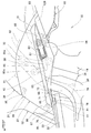
図2は本発明に係る自動二輪車の要部側面図(図中の矢印(FRONT)は車両前方を表す。以下同じ。)であり、前部カバー37は、ステップフロア23よりも一段高く側方に突出させた側方突出部65を備え、この側方突出部65の前部に運転者が足を後に引いたときに足を掛けるサブステップ66を形成し、側方突出部65の後部の下方に、ピリオンステップ31をステップ支持フレーム32に取付けるために開口部67を開けた部材である。
FIG. 2 is a side view of the main part of the motorcycle according to the present invention (the arrow (FRONT in the figure represents the front of the vehicle; the same applies hereinafter)), and the
側方突出部65の前部、詳しくは、サブステップ66の後部は凹部68を備え、この凹部68と、ステップフロア23の後端部に設けた後方突出部71とは、ビス73及びナット74(ステップフロア23に設けたものである。)で連結した部分である。なお、76はフロアフレーム22に設けた内側ブラケット77にボルト78及びナット81(内側ブラケット77に溶接したものである。)で取付けたステップフロア23の後部取付部である。
The front portion of the
開口部67は、前部カバー37の内側に配置したステップ支持フレーム32の側面視コ字形状としたステップ取付部83にピリオンステップ31をスイング自在に取付けたときに、ピリオンステップ31を前部カバー37の外側に通す部分である。図では、ピリオンステップ31は、同乗者がいないときに後方に延びるように倒した状態にある。
When the
ステップ支持フレーム32は、ほぼL字形状に曲げた第1フレーム85と、この第1フレーム85に取付けた第2フレーム86と、第1フレーム85の先端に取付けたステップ取付部83と、このステップ取付部83から一体に後方へ延ばした後方延出部84とからなり、第1フレーム85及び第2フレーム86のそれぞれの一端部85a,86aをリヤフレーム12の側面に取付ける。
88は開口部67の後半部を塞ぐ目隠しカバーであり、ピリオンステップ31を倒した状態では、ピリオンステップ31の内側にほとんどの部分が隠れる。
The
ここで、91,92,93は、後部カバー38に前部カバー37を係止するために後部カバー38側に設けた穴に挿入した前部カバー37側の係止突出片、95は後部カバー38の前端部に設けた前端突出部、96はこの前端突出部95を結合するためにセンタカバー52に設けた上部突出部、97はステップフロア23の後部に設けた上方突出部、98はこの上方突出部97と結合するためにセンタカバー52に設けた下部突出部、99は燃料タンク56(図1参照)に給油するためにセンタカバー52の前部下部の中央に開閉自在に設けた給油用リッドである。
Here, 91, 92, 93 are locking protrusions on the
図3は本発明に係る自動二輪車の要部平面図であり、前部カバー37(輪郭を太線で示した部分である。)のサブステップ66に滑り止めのための複数の凹み102を備え、このサブステップ66の後方の凹部68に設けたビス73でステップフロア23に前部カバー37を固定し、前部カバー37の後部に隣接させたピリオンステップ31を後方へ倒した状態を示す。前部カバー37はステップフロア23と連続するように設けたものである。なお、104,104はステップ支持フレーム32をリヤフレーム12に取付けるためにリヤフレーム12のほぼ車幅方向に貫通させて取付けたボス部である。
FIG. 3 is a plan view of an essential part of the motorcycle according to the present invention, and includes a plurality of
エンジン34は、そのシリンダヘッド106にエアクリーナ18(図1参照)側のスロットルボディ(不図示)と接続する吸気管107を接続し、この吸気管107に燃料噴射弁108を取付けたものである。
In the
燃料噴射弁108と、燃料タンク56に設けた燃料ポンプ111とは、樹脂製の可撓性を有する燃料配管112で接続する。燃料配管112は、シリンダヘッド106に被せたヘッドカバー114に取付けたエンジン側配管支持部材115と、燃料タンク56に取付けたタンク側配管支持部材116とで支持することで、これらのエンジン側配管支持部材115とタンク側配管支持部材116との間に位置する部分を平面視でほぼ車幅方向に延ばした部材である。
The
このように燃料配管112を配置することにより、車体フレーム11側に設けた燃料タンク56に対してパワーユニット14がスイングしたときには、エンジン側配管支持部材115とタンク側配管支持部材116との間の燃料配管112が弾性変形(撓み及び捩れ)して、エンジン側配管支持部材115とタンク側配管支持部材116との変位を吸収する。なお、118は燃料タンク56に設けたフィラーキャップ、121は給油用リッド99(図1参照)を取付ける開口、123は車体前後方向に延びる車体中心線である。
By disposing the
以上の図1〜図3に示したように、本発明は、低床式フロアとしてのステップフロア23を有し、車体フレーム11にパワーユニット14を揺動自在に懸架し、パワーユニット14の上部にエアクリーナ18を設け、このエアクリーナ18上方を車体カバー21で覆うようにしたスクータ型車両としての自動二輪車10において、車体カバー21の下部を垂下してエアクリーナ18と側面視で重なるようにし、車体カバー21のエアクリーナ18と重なる部分を前部カバー37及び後部カバー38に分割し、この前部カバー37をステップフロア23に連続して設けたことを特徴とする。
As shown in FIGS. 1 to 3, the present invention has a
前部カバー37を着脱自在にすることで大型の車体カバー21全体を取外すことなしに、車体カバー21内のエアクリーナ18のメンテナンス、例えばエアクリーナエレメントの交換を容易に行うことができる。
By making the
また、前部カバー37をステップフロア23に連続して設けたので、ほぼ水平なステップフロア23と前部カバー37とをほぼ水平な部分、即ち、後方突出部71と凹部68とで結合する構造とすることができ、車体カバー21の側面にビス等の連結部材が露出しないようにすることができて、自動二輪車10の外観性を向上させることができ、商品性を高めることができる。
In addition, since the
即ち、後部カバー38を大型化しても、後部カバー38を外すことなく、前部カバー37のみを外す構造としたことで、後部カバー38が1枚構造であるために後部カバー38の外観性を向上させることができるとともに、エアクリーナ18のメンテナンスが可能になる。
That is, even if the
また、本発明は、前部カバー37の前部に、ステップフロア23よりも一段高い足置き部としてのサブステップ66を備えることを特徴とする。
前部カバー37にサブステップ66を備えるので、運転者が足を引いたときに足を置く場所を確保することができ、自動二輪車10の使い勝手を向上させることができる。
The present invention is characterized in that the front portion of the
Since the
更に本発明は、前部カバー37に開口部67を設け、車体フレーム11側で揺動自在に支持したピリオンステップ31を開口部67より臨ませたことを特徴とする。
前部カバー37によって、エアクリーナ18の側方を覆うカバーと、ピリオンステップ31の車体フレーム11への取付部(即ち、ステップ支持ブラケット32である。)周囲を覆うカバーを兼用することができる。
Further, the present invention is characterized in that an
The
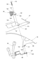
図4は本発明に係る前部カバー及びその周囲を示す要部平面図であり、ピリオンステップ31を車体側方へ起こして同乗者が足を載置可能な状態にしたことを示す。
図中の125はステップ支持フレーム32の後方延出部84に取付けたナット(不図示)にねじ込んだビスであり、このビス125で後方延出部84に前部カバー37、後部カバー38及び目隠しカバー88を固定する。
FIG. 4 is a main part plan view showing the front cover and its surroundings according to the present invention, showing that the
In the figure,
また、後方延出部84に設けた貫通穴126は後部カバー38の一部を支持する(詳細は後述する)。なお、128は前部カバー37の側方突出部65よりも一段低く且つ後方の位置で側方に突出させた下部側方突出部、129はピリオンステップ31をスイングさせるためにステップ取付部83に設けたステップ支軸である。
Further, the through
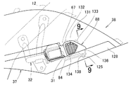
図5は本発明に係る前部カバー及びその周囲を示す第1要部側面図であり、図4の5矢視図である。
目隠しカバー88は、前部カバー37の内外を通気してエアクリーナ18(図1参照)に空気を導入するルーバー131と、開口部67の縁部に掛ける小係止部132〜134と、ステップ支持フレーム32の後方延出部84に取付ける下方膨出部136とを備える。なお、138はビス125をねじ込むために後方延出部84の下面に取付けたナットである。
FIG. 5 is a side view of the first main part showing the front cover and the periphery thereof according to the present invention, and is a view taken in the direction of arrow 5 in FIG.
The
図6は本発明に係る前部カバー及びその周囲を示す第2要部側面図であり、図5の状態からピリオンステップ31(図5参照)及び目隠しカバー88(図5参照)を外した状態を示す。 FIG. 6 is a side view of the second main part showing the front cover and its surroundings according to the present invention, with the pillion step 31 (see FIG. 5) and the blindfold cover 88 (see FIG. 5) removed from the state of FIG. Indicates.
開口部67は、ピリオンステップ31を通す前部開口部141と、目隠しカバー88(図5参照)を嵌める後部開口部142とからなり、前部開口部141にステップ支持フレーム32のステップ取付部83を臨ませる。なお、83a,83aはステップ支軸129(図4参照)を取付けるためにステップ取付部83に開けた支軸嵌合穴である。
The
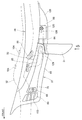
図7は本発明に係るピリオンステップ支持フレーム及びその周囲を示す要部側面図であり、図6の状態から前部カバー37(図6参照)を外した状態を示す。
後部カバー38は、エアクリーナ18の前部の車体外方に下方張り出し部145を一体に備え、この下方張り出し部145に、エアクリーナ18側のビス146を露出させる窓部147と、ほぼ車体側方に屈曲させた側方張り出し部148とを備える。
FIG. 7 is a side view of the main part showing the pillion step support frame and its surroundings according to the present invention, and shows a state in which the front cover 37 (see FIG. 6) is removed from the state of FIG.
The
側方張り出し部148は、ビス125(図4参照)を通すビス挿通穴151と、ステップ支持フレーム32の貫通穴126(図4参照)に嵌合させる突出片152とを設けた部分である。
The
図中の155,156はビスであり、上記したビス146と同様に、エアクリーナ18を構成するケース本体(不図示)にケースカバー158を取付けるための複数のビスの一部である。上記のビス146,155は、後部カバー38に前部カバー37を取付けたときには前部カバー37の内側に隠れるが、前部カバー37を外すことで、ケースカバー158を固定する他のビスと同様にビス146,155を工具で弛めることができ、ケースカバー158をケース本体から外して、例えば、エアクリーナエレメントの交換を行うことができる。なお、161は無段変速機35の変速機カバー162に設けた突出部163にエアクリーナ18(詳しくは、ケース本体である。)を取付けるビスである。
In the drawing,
以上に述べた前部カバー37、後部カバー38、目隠しカバー88を一括して固定する要領を次に説明する。
図8は本発明に係るカバー類の取付構造を示す説明図である。
まず、車体フレーム側のステップ支持フレーム32の貫通穴126に後部カバー38の突出片152が嵌るように車体フレームに後部カバー38を取付ける。
次に、後部カバー38に前部カバー37を取付ける。
そして、前部カバー37の後部開口部142に目隠しカバー88を嵌める。
A procedure for fixing the
FIG. 8 is an explanatory view showing a cover mounting structure according to the present invention.
First, the
Next, the
Then, the
このとき、後部カバー38のビス挿通穴151、前部カバー37の後部開口部142の下方に設けた結合穴部165、目隠しカバー88の下方膨出部136に設けた固定用穴166とは、ステップ支持フレーム32の後方延出部84に開けたビス挿通穴167(ビス125を通す穴である。)を通る直線170上に重なる。
At this time, the
次に、ビス125を、固定用穴166、結合穴部165、ビス挿通穴151及びビス挿通穴167に通し、ナット138にねじ込む。これで、ステップ支持フレーム32への、後部カバー38、前部カバー37及び目隠しカバー88の取付けが完了する。
Next, the
図9は図5の9−9線断面図であり、車体フレーム側に後部カバー38、前部カバー37及び目隠しカバー88(クロスハッチングを施した部分である。)を一括して固定するカバー類固定部175は、ステップ支持フレーム32の後方延出部84に、後部カバー38の側方張り出し部148、前部カバー37の結合穴部165を備える窪み部172、目隠しカバー88の下方膨出部136を重ね、固定用穴166、長穴状としたビス挿通穴151、ビス挿通穴167に通したビス125をナット138にねじ込んで固定した部分である。なお、177はワッシャ、178は前部カバー37の下部側方突出部128に一体に備える側壁である。
FIG. 9 is a cross-sectional view taken along line 9-9 in FIG. 5, and covers for fixing the
このように、カバー類固定部175によって、複数のカバー37,38,88を車体フレーム側に一括して迅速に且つ容易に取付けることができ、カバー類の組付性を向上させることができて、生産性を高めることができる。
As described above, the
以上の図5及び図6に示したように、本発明は、開口部67に別体の目隠しカバー88を設けたことを特徴とする。
開口部67に目隠しカバー88を設けることで開口部67を目立たなくすることができ、外観性を向上させることができる。また、開口部67から目隠しカバー88を取外すことで、開口部67にピリオンステップ31を通し易くすることができ、リヤフレーム12のステップ支持フレーム32にピリオンステップ31を取付けた状態での前部カバー37の組付性を向上させることができる。
As shown in FIGS. 5 and 6, the present invention is characterized in that a
By providing the
また本発明は、図8及び図9に示したように、前部カバー37、後部カバー38及び目隠しカバー88を車体フレーム11側、詳しくは、ステップ支持フレーム32の後方延出部84に共締めしたことを特徴とする。
Further, according to the present invention, as shown in FIGS. 8 and 9, the
一箇所で前部カバー37、後部カバー38及び目隠しカバー88をステップ支持フレーム32に取付けることができるため、カバー類の締結構造の簡素化と作業性の効率化とを図ることができる。
Since the
本発明の車体カバー構造は、スクータ型車両に好適である。 The vehicle body cover structure of the present invention is suitable for a scooter type vehicle.
10…スクータ型車両(自動二輪車)、11…車体フレーム、18…エアクリーナ、23…低床式フロア(ステップフロア)、31…ピリオンステップ、37…前部カバー、38…後部カバー、66…足置き部(サブステップ)、67…開口部、88…目隠しカバー。
DESCRIPTION OF
Claims (3)
前記車体カバー(21)の下部を垂下して前記エアクリーナ(18)と側面視で重なるようにし、前記車体カバー(21)の前記エアクリーナ(18)と重なる部分を前部カバー(37)及び後部カバー(38)に分割し、この前部カバー(37)を前記低床式フロア(23)に連続して設けるとともに、
前記前部カバー(37)を前記後部カバー(38)を取り外すことなく着脱自在とし、 前記前部カバー(37)に開口部(67)を設け、前記車体フレーム側で揺動自在に支持したピリオンステップ(31)をこの開口部(67)より臨ませ、
前記開口部(67)に別体の目隠しカバー(88)を設けた、
ことを特徴とするスクータ型車両の車体カバー構造。 The power unit (14) is swingably suspended on the vehicle body frame (11), and an air cleaner (18) is provided above the power unit (14). In the vehicle body cover structure of the scooter type vehicle in which the vehicle body cover (21) covers the vehicle.
The lower portion of the vehicle body cover (21) is suspended so as to overlap the air cleaner (18) in a side view, and the portions of the vehicle body cover (21) overlapping the air cleaner (18) are the front cover (37) and the rear cover. (38), and the front cover (37) is continuously provided on the low floor type floor (23), and
The front cover (37) is detachable without removing the rear cover (38), and an opening (67) is provided in the front cover (37) so as to be swingably supported on the vehicle body frame side. Step (31) is exposed from this opening (67),
A separate blindfold cover (88) is provided in the opening (67).
A vehicle body cover structure for a scooter type vehicle.
Priority Applications (2)
| Application Number | Priority Date | Filing Date | Title |
|---|---|---|---|
| JP2005205568A JP4563883B2 (en) | 2005-07-14 | 2005-07-14 | Scooter-type vehicle body cover structure |
| CN2006100879404A CN1895949B (en) | 2005-07-14 | 2006-06-07 | Vehicle body cover structure of small size motor |
Applications Claiming Priority (1)
| Application Number | Priority Date | Filing Date | Title |
|---|---|---|---|
| JP2005205568A JP4563883B2 (en) | 2005-07-14 | 2005-07-14 | Scooter-type vehicle body cover structure |
Publications (3)
| Publication Number | Publication Date |
|---|---|
| JP2007022257A JP2007022257A (en) | 2007-02-01 |
| JP2007022257A5 JP2007022257A5 (en) | 2008-06-05 |
| JP4563883B2 true JP4563883B2 (en) | 2010-10-13 |
Family
ID=37608638
Family Applications (1)
| Application Number | Title | Priority Date | Filing Date |
|---|---|---|---|
| JP2005205568A Expired - Fee Related JP4563883B2 (en) | 2005-07-14 | 2005-07-14 | Scooter-type vehicle body cover structure |
Country Status (2)
| Country | Link |
|---|---|
| JP (1) | JP4563883B2 (en) |
| CN (1) | CN1895949B (en) |
Families Citing this family (5)
| Publication number | Priority date | Publication date | Assignee | Title |
|---|---|---|---|---|
| JP5005647B2 (en) * | 2008-09-29 | 2012-08-22 | 本田技研工業株式会社 | Scooter type vehicle |
| JP5508898B2 (en) * | 2010-02-23 | 2014-06-04 | 本田技研工業株式会社 | Saddle riding vehicle |
| JP5113226B2 (en) * | 2010-08-19 | 2013-01-09 | 本田技研工業株式会社 | Scooter type vehicle |
| JP6093219B2 (en) * | 2013-03-28 | 2017-03-08 | 本田技研工業株式会社 | Step plate shape of saddle riding type vehicle |
| WO2020188589A1 (en) * | 2019-03-16 | 2020-09-24 | Tvs Motor Company Limited | Footrest assembly for a two-wheeled vehicle |
Citations (5)
| Publication number | Priority date | Publication date | Assignee | Title |
|---|---|---|---|---|
| JPS59128071A (en) * | 1983-01-10 | 1984-07-24 | ヤマハ発動機株式会社 | Scooter type car |
| JPH0858657A (en) * | 1994-08-26 | 1996-03-05 | Suzuki Motor Corp | Frame cover for tandem scooter type vehicle |
| JPH0976969A (en) * | 1995-09-14 | 1997-03-25 | Honda Motor Co Ltd | Body cover structure of scooter type vehicle |
| JP2002284067A (en) * | 2001-03-28 | 2002-10-03 | Honda Motor Co Ltd | Pillion step holder structure for motorcycle |
| WO2004078570A1 (en) * | 2003-03-06 | 2004-09-16 | Yamaha Hatsudoki Kabushiki Kaisha | Saddle riding-type motor vehicle |
Family Cites Families (6)
| Publication number | Priority date | Publication date | Assignee | Title |
|---|---|---|---|---|
| JP2952799B2 (en) * | 1993-08-31 | 1999-09-27 | 本田技研工業株式会社 | Body cover structure for scooter type vehicle |
| JPH09301248A (en) * | 1996-05-15 | 1997-11-25 | Honda Motor Co Ltd | Auxiliary step fitting structure for scooter type vehicle |
| JP4145370B2 (en) * | 1996-06-27 | 2008-09-03 | 本田技研工業株式会社 | Engine cooling structure for scooter type vehicles |
| JP3821900B2 (en) * | 1997-02-07 | 2006-09-13 | ヤマハ発動機株式会社 | Scooter type motorcycle |
| JP4180775B2 (en) * | 2000-07-05 | 2008-11-12 | ヤマハ発動機株式会社 | Exhaust muffler structure for motorcycles |
| JP4052873B2 (en) * | 2002-05-10 | 2008-02-27 | 本田技研工業株式会社 | Scooter type vehicle |
-
2005
- 2005-07-14 JP JP2005205568A patent/JP4563883B2/en not_active Expired - Fee Related
-
2006
- 2006-06-07 CN CN2006100879404A patent/CN1895949B/en not_active Expired - Fee Related
Patent Citations (5)
| Publication number | Priority date | Publication date | Assignee | Title |
|---|---|---|---|---|
| JPS59128071A (en) * | 1983-01-10 | 1984-07-24 | ヤマハ発動機株式会社 | Scooter type car |
| JPH0858657A (en) * | 1994-08-26 | 1996-03-05 | Suzuki Motor Corp | Frame cover for tandem scooter type vehicle |
| JPH0976969A (en) * | 1995-09-14 | 1997-03-25 | Honda Motor Co Ltd | Body cover structure of scooter type vehicle |
| JP2002284067A (en) * | 2001-03-28 | 2002-10-03 | Honda Motor Co Ltd | Pillion step holder structure for motorcycle |
| WO2004078570A1 (en) * | 2003-03-06 | 2004-09-16 | Yamaha Hatsudoki Kabushiki Kaisha | Saddle riding-type motor vehicle |
Also Published As
| Publication number | Publication date |
|---|---|
| JP2007022257A (en) | 2007-02-01 |
| CN1895949B (en) | 2011-03-23 |
| CN1895949A (en) | 2007-01-17 |
Similar Documents
| Publication | Publication Date | Title |
|---|---|---|
| AU2009200308B2 (en) | Electrical component attachment structure for two-wheeled motor vehicle | |
| EP1520968B1 (en) | Exhaust control device of motorcycle | |
| JP2005069198A (en) | Exhaust control device of motorcycle | |
| AU2005203459A1 (en) | Fuel tank mounting structure in saddle-ride type vehicle | |
| JP4563883B2 (en) | Scooter-type vehicle body cover structure | |
| JP4280501B2 (en) | Front cowl mounting structure for motorcycles | |
| JP5049822B2 (en) | Motorcycle front cowl and windscreen mounting structure | |
| JP2006315657A (en) | Arrangement structure for muffler and brake pedal of motorcycle | |
| AU2009200309B2 (en) | Rear frame attachment structure for two-wheeled motor vehicle | |
| JP2006062581A (en) | Body cover structure in motorcycle | |
| US9284006B2 (en) | Straddle type vehicle | |
| JP2010247818A (en) | Motorcycle | |
| JP5806643B2 (en) | Body cover structure for saddle-ride type vehicles | |
| JP4351459B2 (en) | Motorcycle rear cushion unit mounting structure | |
| JP2002284067A (en) | Pillion step holder structure for motorcycle | |
| JP4299099B2 (en) | Scooter type front cover structure | |
| JP2007038865A (en) | Front cover structure of vehicle | |
| JP5637936B2 (en) | Motorcycle body cover | |
| JP4050510B2 (en) | Motorcycle fuel pump mounting structure | |
| JPH09301248A (en) | Auxiliary step fitting structure for scooter type vehicle | |
| JP2011051485A (en) | Motorcycle | |
| JP4520382B2 (en) | Automobile body cover | |
| JP2006315656A (en) | Fuel tank mounting structure of motorcycle | |
| JP2007030829A (en) | Low-floor type vehicle | |
| JP2003205877A (en) | Storage box structure for scooter type motorcycle |
Legal Events
| Date | Code | Title | Description |
|---|---|---|---|
| A521 | Written amendment |
Free format text: JAPANESE INTERMEDIATE CODE: A523 Effective date: 20080417 |
|
| A621 | Written request for application examination |
Free format text: JAPANESE INTERMEDIATE CODE: A621 Effective date: 20080417 |
|
| A131 | Notification of reasons for refusal |
Free format text: JAPANESE INTERMEDIATE CODE: A131 Effective date: 20100224 |
|
| A977 | Report on retrieval |
Free format text: JAPANESE INTERMEDIATE CODE: A971007 Effective date: 20100225 |
|
| A521 | Written amendment |
Free format text: JAPANESE INTERMEDIATE CODE: A523 Effective date: 20100420 |
|
| A131 | Notification of reasons for refusal |
Free format text: JAPANESE INTERMEDIATE CODE: A131 Effective date: 20100608 |
|
| A521 | Written amendment |
Free format text: JAPANESE INTERMEDIATE CODE: A523 Effective date: 20100608 |
|
| TRDD | Decision of grant or rejection written | ||
| A01 | Written decision to grant a patent or to grant a registration (utility model) |
Free format text: JAPANESE INTERMEDIATE CODE: A01 Effective date: 20100727 |
|
| A01 | Written decision to grant a patent or to grant a registration (utility model) |
Free format text: JAPANESE INTERMEDIATE CODE: A01 |
|
| A61 | First payment of annual fees (during grant procedure) |
Free format text: JAPANESE INTERMEDIATE CODE: A61 Effective date: 20100729 |
|
| FPAY | Renewal fee payment (event date is renewal date of database) |
Free format text: PAYMENT UNTIL: 20130806 Year of fee payment: 3 |
|
| R150 | Certificate of patent or registration of utility model |
Ref document number: 4563883 Country of ref document: JP Free format text: JAPANESE INTERMEDIATE CODE: R150 Free format text: JAPANESE INTERMEDIATE CODE: R150 |
|
| FPAY | Renewal fee payment (event date is renewal date of database) |
Free format text: PAYMENT UNTIL: 20140806 Year of fee payment: 4 |
|
| LAPS | Cancellation because of no payment of annual fees |