JP4559873B2 - Card-like medium transport mechanism - Google Patents

Card-like medium transport mechanism Download PDF

Info

Publication number
JP4559873B2
JP4559873B2 JP2005055019A JP2005055019A JP4559873B2 JP 4559873 B2 JP4559873 B2 JP 4559873B2 JP 2005055019 A JP2005055019 A JP 2005055019A JP 2005055019 A JP2005055019 A JP 2005055019A JP 4559873 B2 JP4559873 B2 JP 4559873B2
Authority
JP
Japan
Prior art keywords
card
guide
roller
roll paper
head
Prior art date
Legal status (The legal status is an assumption and is not a legal conclusion. Google has not performed a legal analysis and makes no representation as to the accuracy of the status listed.)
Expired - Fee Related
Application number
JP2005055019A
Other languages
Japanese (ja)
Other versions
JP2006240762A5 (en
JP2006240762A (en
Inventor
茂貴 小口
Current Assignee (The listed assignees may be inaccurate. Google has not performed a legal analysis and makes no representation or warranty as to the accuracy of the list.)
Nidec Sankyo Corp
Original Assignee
Nidec Sankyo Corp
Priority date (The priority date is an assumption and is not a legal conclusion. Google has not performed a legal analysis and makes no representation as to the accuracy of the date listed.)
Filing date
Publication date
Application filed by Nidec Sankyo Corp filed Critical Nidec Sankyo Corp
Priority to JP2005055019A priority Critical patent/JP4559873B2/en
Priority to CN2010102473177A priority patent/CN101898695B/en
Priority to CN2010102473162A priority patent/CN101898700B/en
Priority to CN2006100515499A priority patent/CN1827505B/en
Publication of JP2006240762A publication Critical patent/JP2006240762A/en
Publication of JP2006240762A5 publication Critical patent/JP2006240762A5/ja
Application granted granted Critical
Publication of JP4559873B2 publication Critical patent/JP4559873B2/en
Expired - Fee Related legal-status Critical Current
Anticipated expiration legal-status Critical

Links

Images

Description

本発明は、カード状媒体搬送機構に関する。更に詳しくは、本発明は、印字ヘッド等のヘッドを有するカード状媒体搬送機構に関するものである。   The present invention relates to a card-like medium transport mechanism. More specifically, the present invention relates to a card-like medium transport mechanism having a head such as a print head.

ロール紙を所定長にカットして切符等のカード状媒体を発券する装置として、例えば特開平10−21430号公報に開示された発券装置がある。この発券装置を図34に示す。ロール紙501を搬送手段502によって繰り出してカッター部503で所定長に切断し、切断した券504に印刷部505で駅名情報等の券情報を印刷すると共に、磁気ヘッド506で駅名情報や金額情報等の磁気データを書き込んだ後、発行口507から排出する。また、投入口508から投入された発行済み券の磁気情報を読み取る読み取り磁気ヘッド509を備えている。   As a device for issuing a card-like medium such as a ticket by cutting a roll paper into a predetermined length, for example, there is a ticket issuing device disclosed in Japanese Patent Laid-Open No. 10-21430. This ticket issuing apparatus is shown in FIG. The roll paper 501 is fed out by the conveying means 502, cut into a predetermined length by the cutter unit 503, ticket information such as station name information is printed on the cut ticket 504 by the printing unit 505, and station name information and money amount information are printed by the magnetic head 506. After the magnetic data is written, it is discharged from the issuing port 507. In addition, a reading magnetic head 509 that reads magnetic information of issued tickets inserted from the insertion port 508 is provided.

券の搬送路は読み取り磁気ヘッド509の下流で、発行口507へと通じる搬送路と投入口508へと通じる搬送路とに分岐している。また、この分岐点と読み取り磁気ヘッド509との間で、廃棄される券を取り込んで孔あけ処理を行う廃券パンチ510に通じる搬送路が分岐している。   The ticket conveyance path branches downstream of the reading magnetic head 509 into a conveyance path leading to the issuing port 507 and a conveyance path leading to the insertion port 508. Further, between this branch point and the reading magnetic head 509, a conveyance path leading to a waste ticket punch 510 that takes in a ticket to be discarded and performs a punching process is branched.

この発券装置では、券の発行方向に関して印刷部505の下流側に磁気ヘッド506,509や廃券パンチ510を配置している。このため、投入口508から投入された発行済み券や廃券パンチ510へと搬送される廃券が印刷部505を上流に向けて逆行することはない。即ち、印刷部505において券を逆方向に搬送することはジャム発生の原因となり得るので、印刷部505において券を逆方向に搬送することがない構造としている。   In this ticket issuing apparatus, magnetic heads 506 and 509 and a waste ticket punch 510 are arranged on the downstream side of the printing unit 505 in the ticket issuing direction. For this reason, the issued ticket inserted from the insertion port 508 and the waste ticket conveyed to the waste ticket punch 510 do not go backward toward the printing unit 505 upstream. In other words, since it is possible for the printing unit 505 to transport the ticket in the reverse direction to cause jamming, the printing unit 505 does not transport the ticket in the reverse direction.

また、別のタイプの発券装置として、発行口と投入口とを共通化し、同じ口を利用して新券の発行と発行済み券の取り込みを行うものがある。かかる発券装置では、新券の発行に必要な印刷部等を通るメイン搬送路とは別に、メイン通路の印刷部等を迂回する迂回搬送路を設け、印刷部において券を逆方向に搬送しないようにしている。ロール紙をカットして新券を発行する場合には、メイン通路を利用して新券を搬送し、印刷や磁気データ処理を行った後、共通口から発行する。一方、共通口から取り込んだ発行済み券は、最初はメイン搬送路に入るが、途中で分岐する迂回搬送路に送り込まれ、印刷部を迂回した後、メイン搬送路に戻され、回収部へと搬送される。   As another type of ticket issuing apparatus, there is an apparatus that shares an issue port and an insertion port and issues a new ticket and takes in issued tickets using the same port. In such a ticket issuing apparatus, in addition to the main conveyance path passing through the printing section and the like necessary for issuing a new ticket, a bypass conveyance path that bypasses the printing section and the like of the main path is provided so that the printing section does not convey the ticket in the reverse direction. I have to. When the roll paper is cut and a new ticket is issued, the new ticket is transported using the main passage, printed and magnetic data processed, and then issued from the common port. On the other hand, issued tickets taken from the common port initially enter the main conveyance path, but are sent to a detour conveyance path that branches in the middle, bypass the printing unit, return to the main conveyance path, and return to the collection unit Be transported.

これらのようなロール紙を所定長にカットしてカード状の媒体を発行するタイプの発券装置では、カットしたカード状媒体がロール紙に巻かれていたことに起因してカールしていることがある。このため、搬送路の両側にガイドを設けてカールしたカード状媒体の先端が搬送路途中に設けられた部材に引っかかるのを防止している。
特開平10−21430号
In a ticket issuing apparatus that issues a card-like medium by cutting roll paper such as these to a predetermined length, the cut card-like medium may be curled due to being wound on the roll paper. is there. For this reason, guides are provided on both sides of the conveyance path to prevent the tip of the curled card-like medium from being caught by a member provided in the middle of the conveyance path.
JP-A-10-21430

しかしながら、搬送路の途中に設けられるプリントヘッドの位置にはカールしたカード状媒体の引っかかりを防止するガイドを設けることが困難である。つまり、搬送路の途中に設ける搬送ローラや磁気ヘッドに比べてプリントヘッドは幅広であり、搬送ローラや磁気ヘッドの両脇には上記ガイドを設置できるが、プリントヘッドの両脇には上記ガイドを設置するスペースがない。このため、上記ガイドがプリントヘッドの位置で途切れてしまい、この部分でカード状媒体が引っかかる虞がある。   However, it is difficult to provide a guide for preventing the curled card-like medium from being caught at the position of the print head provided in the middle of the conveyance path. In other words, the print head is wider than the transport roller and magnetic head provided in the middle of the transport path, and the guides can be installed on both sides of the transport roller and magnetic head, but the guides are installed on both sides of the print head. There is no space to install. For this reason, the guide is interrupted at the position of the print head, and the card-like medium may be caught at this portion.

この問題は、上述の発券装置のように印刷部505に対して券が一方向にのみ通過する構造のものや、プリントヘッドとして端面型のものを採用する発券装置でも問題になるが、特に、カード状媒体がプリントヘッドを双方向から通過するタイプの発券装置や、プリントヘッドとして平面型のものを採用する発券装置では、顕著な問題となる。   This problem is also a problem with a structure in which a ticket passes only in one direction with respect to the printing unit 505 as in the above-described ticket issuing apparatus, or a ticket issuing apparatus that employs an end face type as a print head. This is a significant problem in a ticket issuing apparatus in which the card-like medium passes through the print head from both directions and a ticket issuing apparatus that employs a flat type as the print head.

また、上述の特開平10−21430号に記載された発券装置では、発行口507と投入口508を別々に設けており、それぞれに通じる搬送路を別々に設けているので、構造が複雑になると共に部品点数が増加し、装置が大型化してしまう。また、上述のメイン搬送路の他に迂回搬送路を設けている発券装置でも、同様に、搬送路の多さから構造が複雑になると共に部品点数が増加し、装置が大型化してしまうという問題がある。   Further, in the ticket issuing apparatus described in the above-mentioned JP-A-10-21430, the issue port 507 and the insertion port 508 are provided separately, and the conveyance paths leading to each are provided separately, so that the structure becomes complicated. At the same time, the number of parts increases and the apparatus becomes larger. Further, even in the ticket issuing apparatus provided with the detour conveyance path in addition to the main conveyance path described above, similarly, the structure is complicated due to the large number of conveyance paths, the number of parts is increased, and the apparatus is enlarged. There is.

本発明は、たとえカード状媒体がカールしている場合であってもヘッド位置での引っかかりを防止することができるカード状媒体搬送機構を提供することを目的とする。また、本発明は、ヘッド位置において、カード状媒体を往復方向のいずれにも搬送させることができるカード状媒体搬送機構を提供することを目的とする。   An object of the present invention is to provide a card-like medium transport mechanism that can prevent catching at the head position even when the card-like medium is curled. It is another object of the present invention to provide a card-shaped medium transport mechanism that can transport a card-shaped medium in any of the reciprocating directions at the head position.

かかる目的を達成するために本発明は、搬送路上を搬送されるカード状媒体にヘッドを押し当てながら搬送するカード状媒体搬送機構において、ヘッドは搬送路内に進入、退避可能に移動するとともに、ヘッドが退避状態のとき、カード状媒体の搬送方向に沿って移動し搬送路を形成するガイド部が設けられており、ガイド部はヘッドを挟んでカード状媒体の搬送方向上流側と下流側に設けられ搬送路に沿って互いに逆方向に移動することで開閉する2枚の可動ガイドを備え、可動ガイドの対向端には互い違いになる凹凸が形成され、可動ガイドが閉じた状態では対向端の凸部が相手側の凹部に入り込んでカード状媒体の幅方向から見ると可動ガイドの対向端が重なり合っており、可動ガイドは搬送路の両側に配置された固定ガイドの間に配置されているものである。 In order to achieve this object, the present invention provides a card-like medium transport mechanism that transports while pressing the head against a card-like medium transported on a transport path, and the head moves so as to enter and retract in the transport path. When the head is in the retracted state, a guide portion is provided that moves along the card-like medium conveyance direction to form a conveyance path, and the guide portions are located upstream and downstream in the card-like medium conveyance direction with the head interposed therebetween. It is provided with two movable guides that are opened and closed by moving in opposite directions along the conveyance path, and the opposite ends of the movable guides are formed with irregularities that are staggered, and when the movable guide is closed , When protrusions viewed from the width direction of the card media enters the recess of the mating and overlapping opposite ends of the movable guide, the movable guide arrangement between the fixed guides arranged at opposite sides of the conveying path Those which are.

したがって、ヘッドを使用しない場合には、ヘッドを搬送路から退避させる。そして、ヘッドが在った位置にガイド部を移動させると、ヘッド周辺の隙間が塞がれる。カード状媒体はガイド部に案内されてこの位置を通過する。一方、ヘッドを使用する場合には、ガイド部を元の位置に戻すことでヘッドを搬送路内に進入させることができる。また、ヘッド位置において、カード状媒体を往復方向のいずれにも搬送させることが可能になる。
また、本発明のカード状媒体搬送機構は、可動ガイドが、搬送路の両側に配置された固定ガイドの間に配置されている。
Therefore, when the head is not used, the head is retracted from the conveyance path. Then, when the guide portion is moved to the position where the head is, the gap around the head is closed. The card-like medium is guided by the guide portion and passes through this position. On the other hand, when the head is used, the head can enter the transport path by returning the guide portion to the original position. Further, the card-like medium can be transported in any of the reciprocating directions at the head position.
In the card-like medium transport mechanism of the present invention , the movable guide is disposed between fixed guides disposed on both sides of the transport path.

本発明のカード状媒体搬送機構では、ヘッドが搬送路内に進入、退避可能に移動するとともに、ヘッドが退避状態のとき、カード状媒体の搬送方向に沿って移動し搬送路を形成するガイド部を設けているので、ガイド部を移動させることで、ヘッドが在った位置の隙間を塞ぐことができる。このため、変形していないカード状媒体を使用する場合は勿論のこと、たとえカード状媒体がカールや湾曲等していた場合であっても、ヘッド位置で引っかかることなくカード状媒体をスムースに搬送することができる。また、ヘッド位置において、カード状媒体を往復方向のいずれにも搬送させることが可能になる。このため、カード搬送路をその搬送方向毎にそれぞれ設ける必要がなくなり、構造が簡単になると共に部寸点数を減少させることができ、機構を小型化、軽量化することができる。   In the card-like medium transport mechanism of the present invention, the head moves so as to be able to enter and retract in the transport path, and when the head is in the retracted state, the guide section moves along the card-shaped medium transport direction to form the transport path. Therefore, the gap at the position where the head is located can be closed by moving the guide portion. For this reason, when using a card-like medium that is not deformed, even if the card-like medium is curled or curved, the card-like medium is smoothly transported without being caught at the head position. can do. Further, the card-like medium can be transported in any of the reciprocating directions at the head position. For this reason, it is not necessary to provide each card conveyance path for each conveyance direction, the structure is simplified, the number of dimension points can be reduced, and the mechanism can be reduced in size and weight.

以下、本発明の構成を図面に示す最良の形態に基づいて詳細に説明する。なお、本実施形態では、カード状媒体としてロール紙をカットしたものを例に説明しているが、ロール紙をカットしたカード状媒体に限らず、はじめからカード状を成すカード状媒体でも良い。また、カード状媒体としては、紙製のカードに限るものではなく、プラスチック製、金属製、その他の材料製のカード状媒体でも良い。   Hereinafter, the configuration of the present invention will be described in detail based on the best mode shown in the drawings. In this embodiment, the card-like medium is described by taking a roll paper as an example. However, the card-like medium is not limited to the card-like medium from which the roll paper is cut, and may be a card-like medium having a card shape from the beginning. The card-like medium is not limited to a paper card, and may be a card-like medium made of plastic, metal, or other material.

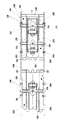
図1〜図31に、本発明のカード状媒体搬送機構を示す。このカード状媒体搬送機構201は、搬送路202上を搬送されるカード状媒体3にヘッド129を押し当てながら搬送するもので、ヘッド129は搬送路202内に進入、退避可能に移動するとともに、ヘッド129が退避状態(図1の状態)のとき、カード状媒体3の搬送方向(図1の矢印A方向)に沿って移動し搬送路202を形成するガイド部203が設けられている。本実施形態では、例えば切符等のカード状媒体(以下、カードという)3を発行するカード発行機1に採用されているカード状媒体搬送機構201を例に説明する。ただし、カード発行機1としては、切符等を発行するものに限るものではないことは勿論である。また、ヘッド129として、例えばカード3に印刷を行う印字ヘッド129を採用している。ただし、印字ヘッド129に限るものでなく、その他のヘッドでも良いことは勿論である。   1 to 31 show a card-like medium transport mechanism of the present invention. The card-like medium carrying mechanism 201 conveys the card-like medium 3 conveyed on the conveying path 202 while pressing the head 129, and the head 129 moves into the conveying path 202 so as to enter and retreat, When the head 129 is in the retracted state (the state shown in FIG. 1), a guide unit 203 is provided that moves along the transport direction (the direction of arrow A in FIG. 1) of the card-like medium 3 and forms the transport path 202. In the present embodiment, a card-like medium transport mechanism 201 employed in a card issuing machine 1 that issues a card-like medium (hereinafter referred to as a card) 3 such as a ticket will be described as an example. However, it is needless to say that the card issuing machine 1 is not limited to a ticket issuing machine. Further, as the head 129, for example, a print head 129 that performs printing on the card 3 is employed. However, the print head 129 is not limited, and other heads may be used.

カード発行機1は、切符等のカード3の発行に使用するものであり、表側が印字面で裏側が磁性面であるロール紙2を所定の長さに切断して、磁性面に磁気データを記録すると共に印字面に文字等を感熱印字してカード3を発行するものである。図33にカード3を示す。ロール紙2の表面の一側には所定間隔でマーク257が付されており、カード発行機1はマーク257に基づいてロール紙2の長さを判断し、所定の長さに切断してカード3とする。なお、図33中符号258で示す領域は、裏面の磁性面において磁気ストライプとして使用しデータを書き込む領域である。また、符号259で示す位置にはカード3の使用時において入場を示す孔があけられ、符号260で示す位置には出場を示す孔があけられる。   The card issuing machine 1 is used for issuing a card 3 such as a ticket, and cuts a roll paper 2 having a printing surface on the front side and a magnetic surface on the back side into a predetermined length, and transfers magnetic data to the magnetic surface. In addition to recording, the card 3 is issued by thermally printing characters on the printing surface. FIG. 33 shows the card 3. Marks 257 are attached to one side of the surface of the roll paper 2 at predetermined intervals, and the card issuing machine 1 determines the length of the roll paper 2 based on the marks 257 and cuts the card into a predetermined length to cut the card. 3. Note that an area denoted by reference numeral 258 in FIG. 33 is an area where data is written and used as a magnetic stripe on the magnetic surface on the back surface. In addition, a hole indicating entry when a card 3 is used is formed at a position indicated by reference numeral 259, and a hole indicating entry is formed at a position indicated by reference numeral 260.

このカード発行機1は、ロール紙2を保持するロール紙の取付機構4と、取付機構4に保持されたロール紙2を取り込んで搬送する第1取込機構5と、搬送中のロール紙2の弛みを形成するループ機構6と、ループ機構6からのロール紙2を取り込んで搬送する第2取込機構7と、ロール紙2を切断してカード3にするカット機構8と、カード3を待機させるカード待機部9と、カード3を直角に方向転換させながら搬送するカード送り機構10と、カード3の磁性面に磁気データを記録及び再生するライトリード部11と、カード3の印字面に印字を行う印字部12と、完成されたカード3を外部に搬出するカード発行部13と、カード3への磁気データの記録及び再生に異常があった場合にそのカード3を回収して収納する回収部14とを備えている。   The card issuing machine 1 includes a roll paper attachment mechanism 4 that holds the roll paper 2, a first take-in mechanism 5 that takes in and transports the roll paper 2 held by the attachment mechanism 4, and the roll paper 2 that is being conveyed. A loop mechanism 6 that forms the slack of the sheet, a second take-in mechanism 7 that takes in and transports the roll paper 2 from the loop mechanism 6, a cut mechanism 8 that cuts the roll paper 2 into a card 3, and a card 3 A card standby unit 9 for standby, a card feeding mechanism 10 for transporting the card 3 while changing its direction at right angles, a write lead unit 11 for recording and reproducing magnetic data on the magnetic surface of the card 3, and a printing surface of the card 3 A printing unit 12 for performing printing, a card issuing unit 13 for carrying out a completed card 3 to the outside, and collecting and storing the card 3 when there is an abnormality in recording and reproduction of magnetic data on the card 3 With the collection unit 14 It is provided.

そして、図4〜図6に示すように、カード発行機1の各部は薄い直方体形状のケーシング15に収容されている。このケーシング15内には、本体シャーシ210が固定されている。本体シャーシ210には、本体シャーシ210との間にガイド部203を取り付けるフレームガイド211と、本体シャーシ210との間に第1取込機構5、ループ機構6、第2取込機構7、カット機構8、カード待機部9、カード送り機構10、ライトリード部11を取り付ける図示しないフレームプレートが取り付けられている。第1取込機構5、ループ機構6、第2取込機構7、カット機構8、カード待機部9、カード送り機構10、ライトリード部11、印字部12、カード発行部13はロール紙2の搬送経路に沿って順に配設されている。また、回収部14はカード送り機構10に連続して配設されている。   As shown in FIGS. 4 to 6, each part of the card issuing machine 1 is accommodated in a thin rectangular parallelepiped casing 15. A main body chassis 210 is fixed in the casing 15. The main body chassis 210 includes a frame guide 211 for attaching the guide portion 203 to the main body chassis 210, and the first take-in mechanism 5, the loop mechanism 6, the second take-in mechanism 7, and the cut mechanism between the main body chassis 210. 8, a frame plate (not shown) for attaching the card standby unit 9, the card feeding mechanism 10, and the write lead unit 11 is attached. The first take-in mechanism 5, the loop mechanism 6, the second take-in mechanism 7, the cut mechanism 8, the card standby unit 9, the card feed mechanism 10, the write lead unit 11, the print unit 12, and the card issue unit 13 are the roll paper 2. They are arranged in order along the transport path. Further, the collection unit 14 is disposed continuously to the card feeding mechanism 10.

また、図1に示すように、搬送路202は、カット機構8からカード送り機構10までの鉛直な第1の直線搬送路159と、カード送り機構10から印字部12までの水平な第2の直線搬送路160と、これら第1の直線搬送路159及び第2の直線搬送路160の間に位置する屈曲部98とから成る。屈曲部98は円弧形状であり、第1の直線搬送路159と第2の直線搬送路160とを90度に方向転換する。これにより、カード発行機1の小型化を図ることができる。さらに、第1の直線搬送路159は、互いに向き合う第1ガイド28及び第2ガイド29から成る。また、第2の直線搬送路160は、互いに向き合う第2ガイド29及び第3ガイド30から成る。屈曲部98は、第2ガイド29と第1ガイド28及び第3ガイド30から成る。本実施形態では屈曲部98はカード3を90度に方向転換するものとしているが、これには限られずカード発行機1での搬送路202の配置に応じて他の曲折角度とすることができる。   As shown in FIG. 1, the conveyance path 202 includes a vertical first linear conveyance path 159 from the cutting mechanism 8 to the card feeding mechanism 10 and a horizontal second line from the card feeding mechanism 10 to the printing unit 12. It comprises a straight conveyance path 160 and a bent portion 98 positioned between the first straight conveyance path 159 and the second straight conveyance path 160. The bent portion 98 has an arc shape and changes the direction of the first straight conveyance path 159 and the second straight conveyance path 160 to 90 degrees. Thereby, size reduction of the card issuing machine 1 can be achieved. Further, the first straight conveyance path 159 includes a first guide 28 and a second guide 29 facing each other. The second straight conveyance path 160 includes a second guide 29 and a third guide 30 that face each other. The bent portion 98 includes a second guide 29, a first guide 28, and a third guide 30. In the present embodiment, the bent portion 98 changes the direction of the card 3 to 90 degrees, but is not limited to this, and other bending angles can be set according to the arrangement of the conveyance path 202 in the card issuing machine 1. .

また、図3及び図4に示すように、ケーシング15にはガイドドア246が設けられている。このガイドドア246は、蝶番19,19により開閉可能に取り付けられている。このガイドドア246の内側面にはスペーサ板248が固着されている。   As shown in FIGS. 3 and 4, the casing 15 is provided with a guide door 246. The guide door 246 is attached by hinges 19 and 19 so as to be opened and closed. A spacer plate 248 is fixed to the inner side surface of the guide door 246.

ガイドドア246を閉じた状態では、搬送路202の幅方向の一方の側部をガイドドア246の内側面又はスペーサ板248によって規制すると共に、搬送路202の幅方向の他方の側部を本体シャーシ210によって規制している。そして、カード3は本体シャーシ210を基準面として搬送される。ガイドドア246の上側には、図3に示すようなカバー板32が取り付けられている。   When the guide door 246 is closed, one side in the width direction of the conveyance path 202 is restricted by the inner side surface of the guide door 246 or the spacer plate 248, and the other side in the width direction of the conveyance path 202 is controlled by the main body chassis. Regulated by 210. Then, the card 3 is conveyed with the main body chassis 210 as a reference plane. A cover plate 32 as shown in FIG. 3 is attached to the upper side of the guide door 246.

ロール紙2の取付機構4は、図7及び図11に示すように、巻回されたロール紙2の中心孔であるロール芯33が嵌め合わされる回転可能なスピンドル34と、このスピンドル34を回転可能に支持する固定軸35と、ロール紙2をスピンドル34に固定するロール紙取付部材36とを備えている。ロール紙取付部材36は、ロール芯33の側方に位置する押さえ部37と、固定軸35内に挿入して保持される被保持部38とを備えている。ここで、スピンドル34にロール芯33を嵌め合わせることにより、ロール紙2が回転可能に支持される。なお、図7中符号262は、本体シャーシ210に固着されたサイドフレームである。   As shown in FIGS. 7 and 11, the roll paper 2 mounting mechanism 4 rotates a rotatable spindle 34 on which a roll core 33, which is a central hole of the rolled paper 2, is fitted, and rotates the spindle 34. A fixed shaft 35 that supports the roll paper 2 and a roll paper attachment member 36 that fixes the roll paper 2 to the spindle 34 are provided. The roll paper mounting member 36 includes a pressing portion 37 positioned on the side of the roll core 33 and a held portion 38 that is inserted and held in the fixed shaft 35. Here, the roll paper 2 is rotatably supported by fitting the roll core 33 to the spindle 34. In FIG. 7, reference numeral 262 denotes a side frame fixed to the main body chassis 210.

固定軸35は、挿入された被保持部38に係止する弾性的に付勢された係止部39を備えている。固定軸35は、ほぼ円筒形状としている。固定軸35の基端面は詳しくは後述すくロール紙シャーシ247にねじ止めにより固定している。固定軸35の外周にはスピンドル34が回転可能に嵌合されている。固定軸35の先端部にはCリング41が嵌合されてスピンドル34の固定軸35からの脱落を防止している。   The fixed shaft 35 includes an elastically biased locking portion 39 that locks the inserted held portion 38. The fixed shaft 35 has a substantially cylindrical shape. In detail, the base end surface of the fixed shaft 35 is fixed to a roll paper chassis 247 described later by screwing. A spindle 34 is rotatably fitted on the outer periphery of the fixed shaft 35. A C-ring 41 is fitted to the distal end portion of the fixed shaft 35 to prevent the spindle 34 from falling off the fixed shaft 35.

係止部39は、固定軸35の中央部付近に形成された1本の直径線上に位置する2本の貫通孔42,42と、各貫通孔42に摺動可能に収容された例えば鋼球であるボール43と、各貫通孔42の外側にねじ止めされた板ばねから成るばね44とから成る。このばね44は、自由端が各貫通孔42の外側を塞ぐように固定軸35のDカット面にねじ止めされている。ここで、ボール43を使用しているので、被保持部38は固定軸35に対して円滑に回転することができる。また、ボール43として鋼球を使用しているので、回転の長寿命化を図ることができる。   The locking portion 39 includes two through holes 42, 42 positioned on one diameter line formed in the vicinity of the center portion of the fixed shaft 35 and, for example, a steel ball slidably accommodated in each through hole 42. And a spring 44 made of a leaf spring screwed to the outside of each through-hole 42. The spring 44 is screwed to the D-cut surface of the fixed shaft 35 so that the free end closes the outside of each through hole 42. Here, since the ball 43 is used, the held portion 38 can smoothly rotate with respect to the fixed shaft 35. In addition, since a steel ball is used as the ball 43, the life of the rotation can be extended.

本実施形態では2本の貫通孔42を直線上に配置しているが、これには限られず例えば90度等の適宜な角度を開けて配置しても良い。また、本実施形態では貫通孔42とボール43とばね44とを2組設けているが、これには限られず1組としたり3組以上設けても良い。さらに、本実施形態ではばね44を板ばねとしているが、これには限られず例えば図12に示すようにボール43を固定軸35の中心側に押圧する圧縮コイルばねとすることができる。この場合、ばね44の外周側を押さえる当て板154を固定軸35のDカット面に取り付ける。また、本実施形態ではボール43を鋼球としているが、これには限られず例えばプラスチックボールとしたり他の材質のものとすることができる。この場合、被保持部38の着脱の際の節度感や操作感を変更することができる。すなわち、本実施形態のようにボール43に鋼球を用いるとカチッとした硬い節度感を得ることができるのに対し、ボール43にプラスチックボールを使用すると軟らかい操作感を得ることができる。   In the present embodiment, the two through holes 42 are arranged on a straight line, but the present invention is not limited thereto, and may be arranged at an appropriate angle such as 90 degrees. In this embodiment, two sets of the through hole 42, the ball 43, and the spring 44 are provided. However, the present invention is not limited to this, and one set or three or more sets may be provided. Further, in the present embodiment, the spring 44 is a leaf spring, but is not limited thereto, and for example, as shown in FIG. 12, a compression coil spring that presses the ball 43 toward the center of the fixed shaft 35 can be used. In this case, a contact plate 154 that holds the outer peripheral side of the spring 44 is attached to the D-cut surface of the fixed shaft 35. In the present embodiment, the ball 43 is a steel ball. However, the present invention is not limited to this. For example, the ball 43 may be a plastic ball or another material. In this case, it is possible to change the feeling of moderation and operation when attaching / detaching the held portion 38. That is, when a steel ball is used for the ball 43 as in the present embodiment, a hard and hard feeling can be obtained, whereas when a plastic ball is used for the ball 43, a soft operation feeling can be obtained.

スピンドル34のフレーム側の端部には外周側に突出したフランジ部34aが形成されている。そして、スピンドル34に嵌合されたロール芯33はフランジ部34aに当接して固定される。ここで、スピンドル34のフランジ34aのロール芯33が当接する面とスピンドル34の先端面との長さはロール芯33の幅よりも僅かに短くしている。このため、固定軸35に装着されたロール紙取付部材36の押さえ部37はロール芯33に当接すると共にスピンドル34に対して僅かに隙間を生ずる。これにより、押さえ部37がロール芯33をフランジ34aに隙間無く押し付けることができる。   A flange portion 34 a that protrudes to the outer peripheral side is formed at an end portion of the spindle 34 on the frame side. The roll core 33 fitted to the spindle 34 is fixed in contact with the flange portion 34a. Here, the length of the surface of the flange 34 a of the spindle 34 with which the roll core 33 abuts and the front end surface of the spindle 34 are slightly shorter than the width of the roll core 33. Therefore, the pressing portion 37 of the roll paper mounting member 36 attached to the fixed shaft 35 abuts on the roll core 33 and creates a slight gap with respect to the spindle 34. Thereby, the press part 37 can press the roll core 33 against the flange 34a without a gap.

被保持部38は、固定軸35の中心孔35aに挿入される中心軸としている。被保持部38の挿入方向の先端部は円錐状としている。そして、被保持部38には、係止部39であるボール43,43が嵌入して係止する係合凹部45が形成されている。係合凹部45は被保持部38の挿入方向の先端部付近に環状に形成されている。また、係合凹部45の挿入方向先端側の段は、外周側を先端側に傾斜した押さえ面45aとしている。   The held portion 38 is a central axis that is inserted into the central hole 35 a of the fixed shaft 35. The tip of the held portion 38 in the insertion direction is conical. The held portion 38 is formed with an engaging recess 45 into which the balls 43 and 43 as the locking portions 39 are fitted and locked. The engaging recess 45 is formed in an annular shape near the distal end in the insertion direction of the held portion 38. Further, the step on the leading end side in the insertion direction of the engaging recess 45 is a pressing surface 45a inclined on the outer peripheral side toward the leading end.

さらに、押さえ部37は、外径がロール紙2のロール芯33の内径よりも若干大きい円板としている。本実施形態では押さえ部37を外径がロール芯33の内径よりも若干大きい円板としているが、これには限られず例えばロール紙2の全体の外径よりも大きい円板としたり、図13に示すようにロール紙2の外径よりも長い2本の腕部を有する十字形板とすることができる。これらの場合、巻回したロール紙2の中心と外周部とが軸方向にずれて円錐状になっていたり円柱状に巻回したロール紙2が不整列で側面に凹凸がある場合には、ロール紙2の側面を押さえ部37により押さえながら回転させることができるので、ロール紙2の安定した供給を行うことができる。   Further, the pressing portion 37 is a disk whose outer diameter is slightly larger than the inner diameter of the roll core 33 of the roll paper 2. In the present embodiment, the holding portion 37 is a disk whose outer diameter is slightly larger than the inner diameter of the roll core 33, but is not limited to this, for example, a disk larger than the entire outer diameter of the roll paper 2, or FIG. As shown in FIG. 4, a cross-shaped plate having two arms longer than the outer diameter of the roll paper 2 can be obtained. In these cases, when the roll paper 2 wound in a cylindrical shape is misaligned with the center and the outer periphery of the rolled paper 2 being axially displaced or in a cylindrical shape, Since the roll paper 2 can be rotated while being pressed by the pressing portion 37, the roll paper 2 can be stably supplied.

そして、被保持部38の挿入方向と反対側の端面には押さえ部37を挟んで摘み46がねじ止めされている。ここで、被保持部38での係合凹部45の形成位置は、被保持部38を固定軸35に挿入して押さえ部37がロール芯33に当接したときにボール43,43が係合凹部45の押さえ面45aを押圧する位置としている。本実施形態ではロール紙取付部材36の被保持部38と押さえ部37と摘み46とを別部材としているが、これには限られず全体を一体成形しても良い。   A knob 46 is screwed to the end surface of the held portion 38 opposite to the insertion direction with the pressing portion 37 interposed therebetween. Here, the formation position of the engaging recess 45 in the held portion 38 is such that the balls 43 and 43 are engaged when the held portion 38 is inserted into the fixed shaft 35 and the pressing portion 37 contacts the roll core 33. The pressing surface 45a of the recess 45 is a position to be pressed. In the present embodiment, the held portion 38, the pressing portion 37, and the knob 46 of the roll paper mounting member 36 are separate members, but the present invention is not limited to this, and the whole may be integrally formed.

固定軸35の中心孔35aに被保持部38を挿入すると、被保持部38の先端部がボール43,43をばね44,44に抗して外周側に移動させる。そして、押さえ部37がロール芯33に当接するまで被保持部38を挿入する。これにより、ボール43,43はばね44,44により中心側に押圧されて係合凹部45に嵌入する。ここで、ボール43は係合凹部45の押さえ面45aに当接する。この押さえ面45aは外周側を挿入方向側に傾斜させているので、被保持部38は挿入方向に向けて付勢される。したがって、ロール紙取付部材36を固定軸35に装着した後にロール芯33にがたつきが発生することを防止できる。   When the held portion 38 is inserted into the center hole 35 a of the fixed shaft 35, the tip end portion of the held portion 38 moves the balls 43, 43 against the springs 44, 44 to the outer peripheral side. Then, the held portion 38 is inserted until the pressing portion 37 contacts the roll core 33. Thereby, the balls 43 and 43 are pressed toward the center by the springs 44 and 44 and are fitted into the engaging recesses 45. Here, the ball 43 abuts against the pressing surface 45 a of the engaging recess 45. Since the pressing surface 45a has the outer peripheral side inclined toward the insertion direction, the held portion 38 is urged toward the insertion direction. Therefore, it is possible to prevent the roll core 33 from rattling after the roll paper mounting member 36 is mounted on the fixed shaft 35.

また、装着されたロール紙2は、スピンドル34及びロール紙取付部材36と一体になって固定軸35に対して回転する。さらに、摘み46を引っ張ると係合凹部45の押さえ面45aがボール43,43をばね44,44に抗して移動させる。そして、被保持部38を固定軸35から抜き出すことができる。   Further, the loaded roll paper 2 is rotated with respect to the fixed shaft 35 integrally with the spindle 34 and the roll paper attachment member 36. Further, when the knob 46 is pulled, the pressing surface 45 a of the engaging recess 45 moves the balls 43, 43 against the springs 44, 44. Then, the held portion 38 can be extracted from the fixed shaft 35.

そして、ロール紙の取付機構4から取り出されたロール紙2は、第1取込機構5に引き込まれる。第1取込機構5は、第1取込ローラ47と、この第1取込ローラ47を回転させる直流モータから成る第1の駆動モータと、第1取込ローラ47にロール紙2を押し付けるテンションローラ49とを備えている。第1取込ローラ47は図示しないフレームプレートと本体シャーシ210とにより回転可能に支持されている。テンションローラ49はホルダ51により回転可能に支持されている。このホルダ51はフレームプレートと本体シャーシ210とにより揺動可能に支持されている。さらに、ホルダ51は、ばね(図示せず)によりテンションローラ49を第1取込ローラ47に付勢している。   Then, the roll paper 2 taken out from the roll paper attachment mechanism 4 is drawn into the first take-in mechanism 5. The first take-in mechanism 5 includes a first take-in roller 47, a first drive motor composed of a DC motor that rotates the first take-in roller 47, and a tension that presses the roll paper 2 against the first take-in roller 47. And a roller 49. The first take-in roller 47 is rotatably supported by a frame plate (not shown) and the main body chassis 210. The tension roller 49 is rotatably supported by the holder 51. The holder 51 is swingably supported by the frame plate and the main body chassis 210. Further, the holder 51 urges the tension roller 49 against the first take-in roller 47 by a spring (not shown).

ループ機構6は、ループローラ53と、このループローラ53を回転可能に支持するループレバー54とを備えている。ループレバー54の基端部はフレームプレートと本体シャーシ210とにより回転可能に支持されている。この支持位置は第1取込ローラ47と第2取込ローラ55とのロール紙2の最短経路(図1中一点鎖線Lで示す)にループレバー54が跨るものとしている。また、このループレバー54に向き合う本体シャーシ210には、図8に示すように円弧形状のスライド孔57が形成されている。スライド孔57の形成位置は、ループレバー54がほぼ水平な状態から約45度下方に傾斜する範囲で回転可能な位置としている。   The loop mechanism 6 includes a loop roller 53 and a loop lever 54 that rotatably supports the loop roller 53. The base end portion of the loop lever 54 is rotatably supported by the frame plate and the main body chassis 210. This support position is such that the loop lever 54 extends over the shortest path (indicated by a one-dot chain line L in FIG. 1) of the roll paper 2 between the first take-in roller 47 and the second take-in roller 55. Further, an arc-shaped slide hole 57 is formed in the main body chassis 210 facing the loop lever 54 as shown in FIG. The slide hole 57 is formed at a position where the loop lever 54 can rotate within a range in which the loop lever 54 is inclined approximately 45 degrees downward from a substantially horizontal state.

さらに、本体シャーシ210の裏側でスライド孔57の最下部にはループレバー54の存在を検出するループセンサ(図示せず)が取り付けられている。このため、ループレバー54が最も下がった状態ではこのループレバー54がループセンサにより検出される。また、ループレバー54が上方に回転した状態ではループレバー54がループセンサから外れて検出されない。   Further, a loop sensor (not shown) for detecting the presence of the loop lever 54 is attached to the bottom of the slide hole 57 on the back side of the main body chassis 210. For this reason, when the loop lever 54 is in the lowest position, the loop lever 54 is detected by the loop sensor. Further, when the loop lever 54 is rotated upward, the loop lever 54 is detached from the loop sensor and is not detected.

これにより、第1取込機構5と第2取込機構7との間でロール紙2が十分な長さのループ59を形成している場合は、ループローラ53が自重でロール紙2を押し下げてループレバー54が最も下がった状態になるので、ループレバー54がループセンサにより検出される。また、第1取込機構5と第2取込機構7との間でロール紙2のループ長が短い場合は、ロール紙2がループローラ53を押し上げてループレバー54が上方に回転した状態になるので、ループレバー54がループセンサにより検出されなくなる。このループセンサの非検出により第1取込機構5を作動させて、ロール紙2のループ59を十分な長さにする。このループ機構6によればループレバー54が第1取込ローラ47と第2取込ローラ55との最短経路に跨っているので、ロール紙2を装着する際にループローラ53に掛け忘れて最短経路にショートカットして掛けてしまうことを防止できる。   Thereby, when the roll paper 2 forms a sufficiently long loop 59 between the first take-in mechanism 5 and the second take-in mechanism 7, the loop roller 53 pushes down the roll paper 2 with its own weight. Since the loop lever 54 is in the lowest position, the loop lever 54 is detected by the loop sensor. When the loop length of the roll paper 2 is short between the first take-in mechanism 5 and the second take-in mechanism 7, the roll paper 2 pushes up the loop roller 53 and the loop lever 54 rotates upward. Therefore, the loop lever 54 is not detected by the loop sensor. The non-detection of the loop sensor activates the first take-in mechanism 5 to make the loop 59 of the roll paper 2 sufficiently long. According to the loop mechanism 6, the loop lever 54 straddles the shortest path between the first take-in roller 47 and the second take-in roller 55. It is possible to prevent the route from being short-cut.

第2取込機構7は、第2取込ローラ55と、この第2取込ローラ55を回転させるステッピングモータから成る第2の駆動モータ(図示せず)と、第2取込ローラ55にロール紙2を押し付けるテンションローラ61とを備えている。第2取込ローラ55はフレームプレートと本体シャーシ210とにより回転可能に支持されている。   The second take-in mechanism 7 includes a second take-up roller 55, a second drive motor (not shown) including a stepping motor that rotates the second take-in roller 55, and a roll on the second take-in roller 55. A tension roller 61 that presses the paper 2 is provided. The second take-in roller 55 is rotatably supported by the frame plate and the main body chassis 210.

第2取込ローラ55とカット機構8との間には、マーク検知センサ21が配置されている。マーク検知センサ21は、ロール紙2に形成されたマーク259を検出することによりロール紙2をカード1枚分の長さだけカット機構8に搬送するためのものである。   A mark detection sensor 21 is disposed between the second take-in roller 55 and the cutting mechanism 8. The mark detection sensor 21 detects the mark 259 formed on the roll paper 2 to convey the roll paper 2 to the cutting mechanism 8 by the length of one card.

カット機構8は、図14に示すように、ロータリカッタ68とカッタ駆動モータ(図示せず)とを備えている。ロータリカッタ68は、ブラケット70に固定された固定刃71と、この固定刃71と平行かつ回転可能に設けられた回転刃72と、回転刃72の一端部に固着されたカッタアーム73とを有している。回転刃72は円柱の一部を面取りして断面D字形状としている。そして、回転刃72の面取り面72aと固定刃71の一側縁との間にロール紙2を通し、回転刃72を回転させて固定刃71との間の剪断力によりロール紙2を切断する。カッタアーム73には長手方向の溝73aが形成されている。この溝73aにカッタ駆動モータによって回転されるカムリング(図示せず)上のカムローラ(図示せず)が入れられている。このため、カッタ駆動モータの回転によりカムリングが回転されると、カムローラが円運動を行い、カッタアーム73を介して回転刃72が回転してロール紙2を切断することができる。そして、ロール紙2はカットされることによりカード3となる。   As shown in FIG. 14, the cutting mechanism 8 includes a rotary cutter 68 and a cutter drive motor (not shown). The rotary cutter 68 includes a fixed blade 71 fixed to the bracket 70, a rotary blade 72 provided in parallel with the fixed blade 71 so as to be rotatable, and a cutter arm 73 fixed to one end of the rotary blade 72. is doing. The rotary blade 72 is chamfered on a part of a cylinder to have a D-shaped cross section. Then, the roll paper 2 is passed between the chamfered surface 72 a of the rotary blade 72 and one side edge of the fixed blade 71, and the roll paper 2 is cut by the shearing force between the rotary blade 72 and the fixed blade 71. . A longitudinal groove 73 a is formed in the cutter arm 73. A cam roller (not shown) on a cam ring (not shown) rotated by a cutter drive motor is placed in the groove 73a. For this reason, when the cam ring is rotated by the rotation of the cutter driving motor, the cam roller performs a circular motion, and the rotary blade 72 rotates through the cutter arm 73 to cut the roll paper 2. Then, the roll paper 2 becomes a card 3 by being cut.

カード待機部9は、カード3を搬送するという指令がホストから出されるまでの間、カード3を保持して待機させるものである。このカード待機部9は、待機搬送ローラ78と待機テンションローラ79とを備えている。待機搬送ローラ78及び待機テンションローラ79は、フレームプレートと本体シャーシ210とにより回転可能に支持されている。待機搬送ローラ78は、直流モータから成る図示しない搬送モータによって回転される。   The card standby unit 9 holds and waits for the card 3 until a command to convey the card 3 is issued from the host. The card standby unit 9 includes a standby conveyance roller 78 and a standby tension roller 79. The standby conveying roller 78 and the standby tension roller 79 are rotatably supported by the frame plate and the main body chassis 210. The standby conveyance roller 78 is rotated by a conveyance motor (not shown) composed of a DC motor.

カット機構8によってカットされたカード3は、待機搬送ローラ78と待機テンションローラ79、駆動ローラ99,100とパッドローラ97、記録部搬送ローラ125と記録部テンションローラ126、再生部搬送ローラ115と再生部テンションローラ127によって搬送路202を第1の直線搬送路159→屈曲98→第2の直線搬送路160の順に搬送されて、印字部12へと搬送される。   The card 3 cut by the cutting mechanism 8 is a standby conveying roller 78 and a standby tension roller 79, driving rollers 99 and 100 and a pad roller 97, a recording unit conveying roller 125 and a recording unit tension roller 126, a reproducing unit conveying roller 115 and a reproducing unit. The section tension roller 127 transports the transport path 202 in the order of the first straight transport path 159 → the bending 98 → the second straight transport path 160, and is transported to the printing unit 12.

屈曲部98にはカード送り機構10が設けられている。カード送り機構10は、屈曲性のあるカード3を第1の直線搬送路159から所定の角度を有する屈曲部98を介して第2の直線搬送路160に走行させるようにしたものである。このカード送り機構10は、屈曲部98の外側に配置した第1駆動ローラ99及び第2駆動ローラ100と、屈曲部98の内側に配置すると共に第1駆動ローラ99及び第2駆動ローラ100に同時に当接可能な共通ローラ97を備えている。   The bent portion 98 is provided with a card feeding mechanism 10. The card feeding mechanism 10 is configured to allow the bendable card 3 to travel to the second straight conveyance path 160 from the first straight conveyance path 159 through a bent portion 98 having a predetermined angle. The card feeding mechanism 10 is disposed on the inner side of the first driving roller 99 and the second driving roller 100 disposed on the outer side of the bent portion 98, and on the inner side of the bent portion 98, and simultaneously on the first driving roller 99 and the second driving roller 100. A common roller 97 capable of contacting is provided.

第1駆動ローラ99は第1ガイド28の開口部から搬送路202に突出している。第2駆動ローラ100は第3ガイド30の開口部から搬送路202に突出している。共通ローラ97は、第2ガイド29の開口部から搬送路202に突出していると共に、第1駆動ローラ99及び第2駆動ローラ100を押圧するテンションローラである。この共通ローラ97の直径は、カード3が屈曲部98を搬送する際にカール癖が付いて印字部12等で引っ掛かるといった悪影響が生じない程度に小さくしている。このため、カード送り機構10の小型化を図ることができる。   The first drive roller 99 protrudes from the opening of the first guide 28 to the conveyance path 202. The second drive roller 100 protrudes from the opening of the third guide 30 into the conveyance path 202. The common roller 97 is a tension roller that protrudes from the opening of the second guide 29 into the conveyance path 202 and presses the first drive roller 99 and the second drive roller 100. The diameter of the common roller 97 is small enough to prevent adverse effects such as curling of the card 3 when the card 3 is transported through the bent portion 98 and being caught by the printing portion 12 or the like. For this reason, size reduction of the card feed mechanism 10 can be achieved.

第1駆動ローラ99と第2駆動ローラ100は、上述した搬送モータによって回転される。   The first drive roller 99 and the second drive roller 100 are rotated by the transport motor described above.

ところで、第1ガイド28の下流側の端部は第1駆動ローラ99と第2駆動ローラ100との間に位置する。そして、第2ガイド29は共通ローラ97に沿って円弧状に直角に折れ曲がり印字部12まで連続している。また、第3ガイド30が回収部14から第2駆動ローラ100を経て印字部12まで連続している。   Incidentally, the downstream end of the first guide 28 is located between the first drive roller 99 and the second drive roller 100. The second guide 29 is bent at right angles in a circular arc along the common roller 97 and continues to the printing unit 12. Further, the third guide 30 continues from the collection unit 14 to the printing unit 12 through the second drive roller 100.

ここで、回収部14から第1ガイド28の下流端部までの間にセレクタ117が設けられている。セレクタ117は、図15に示すように平板形状の板ばねで、回収部14側の端部、即ち上端部117aを下方に直角に折り曲げてリジェクトスタッカ121にねじ止めされている。また、セレクタ117の反対側の端部、即ち下端部117bは第1ガイド28の下流端部で上方に僅かに折れ曲がり第2ガイド29のカード搬送面上に位置している。   Here, a selector 117 is provided between the collection unit 14 and the downstream end of the first guide 28. The selector 117 is a flat plate spring as shown in FIG. 15, and the end on the collection unit 14 side, that is, the upper end 117 a is bent downward at a right angle and is screwed to the reject stacker 121. The opposite end of the selector 117, that is, the lower end 117 b is slightly bent upward at the downstream end of the first guide 28 and is positioned on the card transport surface of the second guide 29.

このセレクタ117は通常はばね圧で下方に位置して搬送路202を塞いでいる。そして、カード3が正方向に搬送されるときは、セレクタ117の下端部117bを押し上げて屈曲部98を通過する。また、カード3がライトリード部11から逆方向に搬送されるときは、カード3はセレクタ117の下端部117bにより上側に案内されて第1駆動ローラ99及び共通ローラ97に取り込まれることなく回収部14に搬送される。   The selector 117 is usually positioned below with spring pressure and closes the conveyance path 202. When the card 3 is conveyed in the forward direction, the lower end portion 117b of the selector 117 is pushed up and passes through the bent portion 98. When the card 3 is conveyed in the reverse direction from the write read unit 11, the card 3 is guided upward by the lower end portion 117 b of the selector 117 and is not taken into the first drive roller 99 and the common roller 97. 14 is conveyed.

また、セレクタ117の上端部117a付近の搬送路202には、リジェクト搬送ローラ118と、このリジェクト搬送ローラ118にカード3を押し付けるテンションローラ119とが向き合って配置されている。リジェクト搬送ローラ118はフレームプレートと本体シャーシ210とにより回転可能に支持されている。このリジェクト搬送ローラ118は、第1駆動ローラ99とギヤにより連結されている。このため、例えば図1中でカード3を逆方向(左方向)に搬送する場合は各コーナー搬送ローラ99,100を右回転方向に回転させるので、リジェクト搬送ローラ118は左回転方向に回転されてカード3が回収部14に搬送される。さらに、テンションローラ119はホルダ(図示せず)により回転可能に支持されている。このホルダはフレームプレートと本体シャーシ210とにより回転可能に支持されている。さらに、ホルダは、ばね(図示せず)によりテンションローラ119をリジェクト搬送ローラ118に付勢している。   Further, a reject conveying roller 118 and a tension roller 119 that presses the card 3 against the reject conveying roller 118 are arranged facing each other in the conveying path 202 near the upper end portion 117a of the selector 117. The reject conveyance roller 118 is rotatably supported by the frame plate and the main body chassis 210. The reject conveying roller 118 is connected to the first driving roller 99 by a gear. Therefore, for example, when the card 3 is transported in the reverse direction (left direction) in FIG. 1, the corner transport rollers 99 and 100 are rotated in the clockwise direction, so that the reject transport roller 118 is rotated in the counterclockwise direction. The card 3 is conveyed to the collection unit 14. Further, the tension roller 119 is rotatably supported by a holder (not shown). This holder is rotatably supported by the frame plate and the main body chassis 210. Further, the holder urges the tension roller 119 against the reject conveying roller 118 by a spring (not shown).

ここで、セレクタ117の上端部とリジェクト搬送ローラ118及びテンションローラ119との位置関係は、図16に示すように排出寸前のカード3のセレクタ117の上端部よりも先の部分の重心Wを力点とし、セレクタ117の上端部を支点とし、テンションローラ119への反力Rを作用点としたときに、力点及び支点の距離mと支点及び作用点の距離nとの比m:nが約4.5:1となるようにしている。この比率にすることにより、カード3は排出される直前までに先端側が十分に重くなると共にカード3の後端はテンションローラ119の回転により跳ね上げられるので、排出されたカード3はカード先端3aが下向きとなって落とされる。このため、カード3が排出により先端が跳ね上がってリジェクトスタッカ121の上部に引っかかってリジェクト搬送ローラ118及びテンションローラ119により再び搬送路202に引き込まれることを防止できる。   Here, the positional relationship between the upper end portion of the selector 117 and the reject conveying roller 118 and the tension roller 119 is such that, as shown in FIG. 16, the center of gravity W of the portion ahead of the upper end portion of the selector 117 of the card 3 just before discharge is a power point. When the upper end of the selector 117 is a fulcrum and the reaction force R to the tension roller 119 is an action point, the ratio m: n of the distance m between the force point and the fulcrum and the distance n between the fulcrum and the action point is about 4 .5: 1. By setting this ratio, the front end side of the card 3 becomes sufficiently heavy immediately before being ejected and the rear end of the card 3 is flipped up by the rotation of the tension roller 119. Dropped downward. For this reason, it can be prevented that the leading edge of the card 3 jumps up due to the ejection and is caught on the upper portion of the reject stacker 121 and is again drawn into the transport path 202 by the reject transport roller 118 and the tension roller 119.

回収部14は、図16,図17に示すように、リジェクトスタッカ121と規制ガイド122とを備えている。リジェクトスタッカ121は、セレクタ117の上端部の下方に位置する側板部121aと、この側板部121aの下端からケーシング15の側部にまで位置する底板部121bとを備えている。底板部121bはケーシング15の側部側を下方にして傾斜している。   As shown in FIGS. 16 and 17, the collection unit 14 includes a reject stacker 121 and a regulation guide 122. The reject stacker 121 includes a side plate portion 121a located below the upper end portion of the selector 117, and a bottom plate portion 121b located from the lower end of the side plate portion 121a to the side portion of the casing 15. The bottom plate 121b is inclined with the side of the casing 15 facing downward.

規制ガイド122は、セレクタ117の延長線上、即ちカード3の排出方向に沿って、その上側に設けられている。このため、図17に示すように、カード3がリジェクト搬送ローラ118により排出される際に巻き癖により上向きに湾曲している場合でも、規制ガイド122によりカード3の湾曲が下方に矯正される。このため、排出されたカード3が失速してリジェクトスタッカ121の上部に引っかかって再び搬送路202に引き込まれることを防止できる。しかも、排出されたカード3は順番に重ねられるので、不良カード等の管理を容易に行うことができる。   The restriction guide 122 is provided on the extension line of the selector 117, that is, on the upper side along the card 3 ejection direction. For this reason, as shown in FIG. 17, even when the card 3 is curved upward by the curl when being ejected by the reject conveying roller 118, the curving of the card 3 is corrected downward by the regulation guide 122. For this reason, it is possible to prevent the discharged card 3 from being stalled and caught on the upper portion of the reject stacker 121 and drawn into the transport path 202 again. Moreover, since the discharged cards 3 are stacked in order, it is possible to easily manage defective cards and the like.

カード送り機構10から正常に搬送されたカード3は、第2ガイド29及び第3ガイド30から成る搬送路202に案内されてライトリード部11に搬送される。ライトリード部11は、カード3に所定の磁気データを記録するための記録ヘッド123と、この記録ヘッド123の下流側に配置されると共にカード3に記録された磁気データを読み出す再生ヘッド124とを備えている。これらのヘッド123,124のヘッド面は、第2ガイド29の開口部から搬送路202に突出してバックアップローラ(図示せず)に圧接している。このバックアップローラは第3ガイド30の開口部から搬送路202に突出している。   The card 3 normally conveyed from the card feeding mechanism 10 is guided to the conveyance path 202 including the second guide 29 and the third guide 30 and conveyed to the write lead unit 11. The write read unit 11 includes a recording head 123 for recording predetermined magnetic data on the card 3 and a reproducing head 124 that is arranged on the downstream side of the recording head 123 and reads the magnetic data recorded on the card 3. I have. The head surfaces of the heads 123 and 124 protrude from the opening of the second guide 29 to the conveyance path 202 and are in pressure contact with a backup roller (not shown). The backup roller protrudes from the opening of the third guide 30 to the conveyance path 202.

また、記録ヘッド123のバックアップローラと同軸上に記録部搬送ローラ125が設けられている。そして、再生ヘッド124のバックアップローラと同軸上に再生部搬送ローラ115が設けられている。これら搬送ローラ125,115は第3ガイド30の開口部から搬送路202に突出している。   Further, a recording unit conveying roller 125 is provided coaxially with the backup roller of the recording head 123. A reproducing unit conveying roller 115 is provided coaxially with the backup roller of the reproducing head 124. These transport rollers 125 and 115 protrude into the transport path 202 from the opening of the third guide 30.

さらに、記録部搬送ローラ125に搬送路202を挟んで向き合う位置、即ち記録ヘッド123に対してカード3の幅方向に重なる位置に記録部テンションローラ126が設けられて記録部搬送ローラ125を押圧している。また、再生部搬送ローラ115に搬送路202を挟んで向き合う位置、即ち再生ヘッド124に対してカード3の幅方向に重なる位置に再生部テンションローラ127が設けられて再生部搬送ローラ115を押圧している。これらテンションローラ126,127は第2ガイド29の開口部から搬送路202に突出している。   Further, a recording unit tension roller 126 is provided at a position facing the recording unit conveyance roller 125 across the conveyance path 202, that is, a position overlapping the recording head 123 in the width direction of the card 3 to press the recording unit conveyance roller 125. ing. Further, a reproduction unit tension roller 127 is provided at a position facing the reproduction unit conveyance roller 115 with the conveyance path 202 interposed therebetween, that is, a position overlapping the reproduction head 124 in the width direction of the card 3, and presses the reproduction unit conveyance roller 115. ing. These tension rollers 126 and 127 protrude from the opening of the second guide 29 into the conveyance path 202.

記録部搬送ローラ125及び再生部搬送ローラ115はフレームプレートと本体シャーシ210とにより回転可能に支持されている。これら記録部搬送ローラ125及び再生部搬送ローラ115はカード送り機構10の第2駆動ローラ100と共に図示しないモータによって回転される。   The recording unit conveyance roller 125 and the reproduction unit conveyance roller 115 are rotatably supported by the frame plate and the main body chassis 210. The recording unit conveying roller 125 and the reproducing unit conveying roller 115 are rotated by a motor (not shown) together with the second driving roller 100 of the card feeding mechanism 10.

記録部テンションローラ126及び再生部テンションローラ127は、それぞれホルダ(図示せず)により回転可能に支持されている。各ホルダはフレームプレートと本体シャーシ210とにより回転可能に支持されている。さらに、各ホルダは、ばね(図示せず)により各テンションローラ126,127を各搬送ローラ125,115に付勢している。   The recording unit tension roller 126 and the reproducing unit tension roller 127 are rotatably supported by holders (not shown). Each holder is rotatably supported by the frame plate and the main body chassis 210. Further, each holder urges each tension roller 126, 127 to each conveying roller 125, 115 by a spring (not shown).

ライトリード部11と印字部12との間には、図示しない印字タイミングセンサが配置されている。この印字タイミングセンサによりカード3のサーマル面に印字を行うタイミングが図られる。   A print timing sensor (not shown) is disposed between the write lead unit 11 and the print unit 12. The timing for printing on the thermal surface of the card 3 is achieved by this print timing sensor.

印字部12は、印字ヘッド129を備えている。印字ヘッド129は、例えばサーマルヘッドである。印字ヘッド129は、図32に示す駆動機構により図1に示す退避位置と図2に示す印字位置(進入位置)との間で移動される。本実施形態では、印字ヘッド129として、搬送路202に対して傾斜させた状態で使用する平面型の印字ヘッドを使用している。ただし、搬送路202に対して水平状態で使用する平面型の印字ヘッドを使用しても良く、さらには、端面型の印字ヘッドを使用しても良い。   The printing unit 12 includes a print head 129. The print head 129 is a thermal head, for example. The print head 129 is moved between the retracted position shown in FIG. 1 and the print position (entrance position) shown in FIG. 2 by the drive mechanism shown in FIG. In this embodiment, as the print head 129, a planar print head used in a state where it is inclined with respect to the conveyance path 202 is used. However, a flat type print head used in a horizontal state with respect to the conveyance path 202 may be used, and furthermore, an end face type print head may be used.

ガイド部203は、図18〜図31に詳しく示すように、サーマルヘッド129及びプラテンローラ204を挟んで配置された前後2つのガイドユニット205,206と、各ガイドユニット205,206を駆動する駆動手段207より構成されている。各ガイドユニット205,206は、搬送路202の両側に配置された2枚の上固定ガイド208と、各上固定ガイド208の間に配置された可動ガイド209を備えている。   As shown in detail in FIGS. 18 to 31, the guide unit 203 includes two front and rear guide units 205 and 206 disposed with the thermal head 129 and the platen roller 204 interposed therebetween, and driving means for driving the guide units 205 and 206. 207. Each of the guide units 205 and 206 includes two upper fixed guides 208 disposed on both sides of the conveyance path 202 and a movable guide 209 disposed between the upper fixed guides 208.

各ガイドユニット205,206の上固定ガイド208は、本体シャーシ210又はフレームガイド211に固着されている。上固定ガイド208は、本体シャーシ210又はフレームガイド211に固着されている下固定ガイド212との間に所定の隙間をあけて配置されており、上固定ガイド208と下固定ガイド212との間が搬送路202になっている。なお、下固定ガイド212は、プラテンローラ204を挟んで前後(カード3の搬送方向上流側と下流側)に設けられている。   The upper fixed guide 208 of each guide unit 205, 206 is fixed to the main body chassis 210 or the frame guide 211. The upper fixing guide 208 is disposed with a predetermined gap between the upper fixing guide 208 and the lower fixing guide 212 fixed to the main body chassis 210 or the frame guide 211. It is a conveyance path 202. The lower fixed guide 212 is provided on the front and rear (the upstream side and the downstream side in the card 3 conveyance direction) with the platen roller 204 interposed therebetween.

前側(搬送方向上流側)ガイドユニット205の可動ガイド209は1本の固定ガイド軸213によって図18に示す位置から後側に向けてスライド可能に支持されており、後側(搬送方向下流側)ガイドユニット206の可動ガイド209は2本の固定ガイド軸213によって図18に示す位置から前側に向けてスライド可能に支持されている。なお、前側ガイドユニット205の可動ガイド209を支持する固定ガイド軸213は1本であるが、この可動ガイド209には駆動手段207のスライドレバー214が連結されているので、可動ガイド209が固定ガイド軸213を中心に揺動してしまうことはない。可動ガイド209の両脇には側板209aが設けられており、各側板209aにはカード3の搬送方向に細長い長孔215が設けられている。各長孔215に固定ガイド軸213を貫通させることで可動ガイド209を搬送方向Aにスライド可能に支持している。各固定ガイド軸213の両端部にはガイドスペーサ216がはめ込まれており、可動ガイド209の両脇の上固定ガイド208に対してどちらかに偏らせることなく、両脇の上固定ガイド208の中央に可動ガイド209を位置決めしている。   The movable guide 209 of the front side (upstream in the transport direction) guide unit 205 is supported by one fixed guide shaft 213 so as to be slidable from the position shown in FIG. 18 to the rear side, and on the rear side (downstream in the transport direction). The movable guide 209 of the guide unit 206 is supported by two fixed guide shafts 213 so as to be slidable from the position shown in FIG. Although there is one fixed guide shaft 213 for supporting the movable guide 209 of the front guide unit 205, the movable guide 209 is connected to the slide lever 214 of the driving means 207, so that the movable guide 209 is fixed guide. There is no swinging around the shaft 213. Side plates 209a are provided on both sides of the movable guide 209, and each side plate 209a is provided with an elongated slot 215 that is elongated in the card 3 transport direction. The movable guide 209 is supported so as to be slidable in the transport direction A by passing the fixed guide shaft 213 through the long holes 215. Guide spacers 216 are fitted at both ends of each fixed guide shaft 213 so that the center of the upper fixed guide 208 on both sides is not biased to either side with respect to the upper fixed guide 208 on both sides of the movable guide 209. The movable guide 209 is positioned at the position.

前後のガイドユニット205,206の可動ガイド209の対向端には、互い違いになる凹凸が形成されている。本実施形態では、前側ガイドユニット205の可動ガイド209の後端に2つの凹部217を設け、後側ガイドユニット206の可動ガイド209の先端には2つの凸部218を設けている。   The opposite ends of the movable guides 209 of the front and rear guide units 205 and 206 are formed with irregularities that are staggered. In the present embodiment, two concave portions 217 are provided at the rear end of the movable guide 209 of the front guide unit 205, and two convex portions 218 are provided at the tip of the movable guide 209 of the rear guide unit 206.

前側ガイドユニット205の可動ガイド209には、パッドローラ219を搬送路202に突出させる長孔209dが設けられている。パッドローラ219を回転自在に支持するパッドレバー220は、前側ガイドユニット205の可動ガイド209に重ねるように配置され、可動ガイド209と一緒に固定ガイド軸213に支持されている。パッドレバー220と本体シャーシ210との間にはパッドばね221が伸ばされた状態で設けられており、パッドばね221によってパッドローラ219は搬送路202に突出する方向に付勢されている。パッドローラ219の下には、駆動ローラ222が設けられている。   The movable guide 209 of the front guide unit 205 is provided with a long hole 209d for causing the pad roller 219 to protrude into the conveyance path 202. The pad lever 220 that rotatably supports the pad roller 219 is disposed so as to overlap the movable guide 209 of the front guide unit 205, and is supported by the fixed guide shaft 213 together with the movable guide 209. A pad spring 221 is provided between the pad lever 220 and the main body chassis 210 in an extended state, and the pad roller 219 is urged by the pad spring 221 in a direction in which the pad roller 219 protrudes into the conveyance path 202. A drive roller 222 is provided below the pad roller 219.

このようにパッドレバー220を可動ガイド209に重ねるように配置しているので、機構を小型化することができる。また、パッドレバー220と可動ガイド209を共通の固定ガイド軸213によって支持することで、いわばパッドレバー220の支点軸と可動ガイド209のガイド軸とを共通化することができるので、機構を小型化することができる。   Since the pad lever 220 is arranged so as to overlap the movable guide 209 in this way, the mechanism can be reduced in size. Further, by supporting the pad lever 220 and the movable guide 209 with a common fixed guide shaft 213, the fulcrum shaft of the pad lever 220 and the guide shaft of the movable guide 209 can be shared, so the mechanism is downsized. can do.

また、後側ガイドユニット206の可動ガイド209には、パッドローラ223を搬送路202に突出させる長孔209bと、パッドローラ224を媒体搬送路202に突出させる長孔209cが設けられている。パッドローラ223を回転自在に支持するパッドレバー225は、後側ガイドユニット206の可動ガイド209に重ねるように配置され、可動ガイド209と一緒に固定ガイド軸213に支持されている。また、パッドローラ224を回転自在に支持するパッドレバー226は、パッドレバー225と可動ガイド209との間に重ねるように配置され、可動ガイド209と一緒に固定ガイド軸213に支持されている。パッドレバー225及びパッドレバー226と本体シャーシ210との間にはパッドばね227が伸ばされた状態で設けられており、パッドばね227によってパッドローラ223,224は搬送路202に突出する方向に付勢されている。各パッドローラ223,224の下には、駆動ローラ228,229がそれぞれ設けられている。   Further, the movable guide 209 of the rear guide unit 206 is provided with a long hole 209 b for projecting the pad roller 223 into the transport path 202 and a long hole 209 c for projecting the pad roller 224 into the medium transport path 202. The pad lever 225 that rotatably supports the pad roller 223 is disposed so as to overlap the movable guide 209 of the rear guide unit 206, and is supported by the fixed guide shaft 213 together with the movable guide 209. The pad lever 226 that rotatably supports the pad roller 224 is disposed so as to overlap between the pad lever 225 and the movable guide 209, and is supported by the fixed guide shaft 213 together with the movable guide 209. A pad spring 227 is extended between the pad lever 225 and the pad lever 226 and the main body chassis 210, and the pad rollers 223 and 224 are urged by the pad spring 227 in a direction in which the pad rollers 223 and 224 protrude into the conveyance path 202. Has been. Drive rollers 228 and 229 are provided below the pad rollers 223 and 224, respectively.

このようにパッドレバー225とパッドレバー226を重ね、更に可動ガイド209に重ねるように配置しているので、機構を小型化することができる。また、パッドレバー225と可動ガイド209を共通の固定ガイド軸213によって支持することで、いわばパッドレバー225の支点軸と可動ガイド209のガイド軸とを共通化することができ、パッドレバー226と可動ガイド209を共通の固定ガイド軸213によって支持することで、いわばパッドレバー226の支点軸と可動ガイド209のガイド軸とを共通化することができるので、機構を小型化することができる。   As described above, the pad lever 225 and the pad lever 226 are overlapped and arranged so as to overlap the movable guide 209, so that the mechanism can be miniaturized. Further, by supporting the pad lever 225 and the movable guide 209 by a common fixed guide shaft 213, the fulcrum shaft of the pad lever 225 and the guide shaft of the movable guide 209 can be shared, and the pad lever 226 and the movable guide 209 are movable. By supporting the guide 209 with the common fixed guide shaft 213, the fulcrum shaft of the pad lever 226 and the guide shaft of the movable guide 209 can be shared, so that the mechanism can be miniaturized.

駆動手段207は、本体シャーシ210に固定されたソレノイド230と、ソレノイドレバー支点軸231によって揺動可能に本体シャーシ210に取り付けられてソレノイド230によって揺動されるソレノイドレバー232と、ソレノイドレバー232によって前後方向に移動する2本のスライドレバー214と、スライドレバー214と後側ガイドユニット206の可動ガイド209を連結する2本のレバー233を備えている。2本のスライドレバー214は、その前後部分を連動軸234,235によって連結され一体となってスライドする。後側の連動軸235にはソレノイドレバー232が連結されている。また、各スライドレバー214の前端にはアーム236がそれぞれ一体成形されており、各アーム236の先端は連動軸237によって前側ガイドユニット205の可動ガイド209にそれぞれ連結されている。レバー233は、駆動ローラ229が固定されているシャフト238にレバースリーブ239を介して揺動可能に取り付けられている。レバー233の一端は軸262を介してスライドレバー214に、他端は軸263を介して後側ガイドユニット206の可動ガイド209にそれぞれ連結されている。ソレノイドレバー232には軸264が取り付けられており、軸264と本体シャーシ210との間にはコイルスプリング240が伸びた状態で設けられている。   The driving means 207 includes a solenoid 230 fixed to the main body chassis 210, a solenoid lever 232 that is attached to the main body chassis 210 so as to be swingable by the solenoid lever fulcrum shaft 231, and is swung by the solenoid 230. Two slide levers 214 that move in the direction, and two levers 233 that connect the slide lever 214 and the movable guide 209 of the rear guide unit 206 are provided. The two slide levers 214 slide together as a result of their front and rear portions being connected by interlocking shafts 234 and 235. A solenoid lever 232 is connected to the rear interlocking shaft 235. In addition, an arm 236 is integrally formed at the front end of each slide lever 214, and the tip of each arm 236 is connected to the movable guide 209 of the front guide unit 205 by an interlocking shaft 237. The lever 233 is swingably attached to a shaft 238 to which the driving roller 229 is fixed via a lever sleeve 239. One end of the lever 233 is connected to the slide lever 214 via the shaft 262, and the other end is connected to the movable guide 209 of the rear guide unit 206 via the shaft 263. A shaft 264 is attached to the solenoid lever 232, and a coil spring 240 is extended between the shaft 264 and the main body chassis 210.

ソレノイド230がオフ状態の場合には、コイルスプリング240によってソレノイドレバー232が図18に示す位置に引き寄せられており、スライドレバー214は前側ガイドユニット205の可動ガイド209を前側に移動させている。また、レバー233は後側ガイドユニット206の可動ガイド209を後側に移動させている。即ち、前後の可動ガイド209が開いている。   When the solenoid 230 is off, the solenoid lever 232 is attracted to the position shown in FIG. 18 by the coil spring 240, and the slide lever 214 moves the movable guide 209 of the front guide unit 205 to the front side. The lever 233 moves the movable guide 209 of the rear guide unit 206 to the rear side. That is, the front and rear movable guides 209 are open.

この状態からソレノイド230がオン操作されると、図19に示すようにソレノイド230がコイルスプリング240の付勢力に抗してソレノイドレバー232を揺動させる。このため、スライドレバー214が後側にスライドし、前側ガイドユニット205の可動ガイド209を後側にスライドさせる。また、スライドレバー214のスライドによってレバー233が揺動し、後側ガイドユニット206の可動ガイド209を前側に移動させる。このため、前後の可動ガイド209が閉じる。閉じた状態では、後側ガイドユニット206の可動ガイド209の凸部218が前側ガイドユニット205の可動ガイド209の凹部217に入り込んでおり、カード3の幅方向から見ると各可動ガイド209の端部が重なり合う構造となっている。このため、各可動ガイド209ユニット205,206間をカード3が往復方向のいずれの方向にもスムースに通過することができる。   When the solenoid 230 is turned on from this state, the solenoid 230 swings the solenoid lever 232 against the urging force of the coil spring 240 as shown in FIG. For this reason, the slide lever 214 slides rearward, and the movable guide 209 of the front guide unit 205 is slid rearward. Further, the lever 233 is swung by the slide of the slide lever 214, and the movable guide 209 of the rear guide unit 206 is moved to the front side. For this reason, the front and rear movable guides 209 are closed. In the closed state, the convex portion 218 of the movable guide 209 of the rear guide unit 206 enters the concave portion 217 of the movable guide 209 of the front guide unit 205, and the end portion of each movable guide 209 when viewed from the width direction of the card 3. It has a structure that overlaps. For this reason, the card | curd 3 can pass smoothly between any movable guide 209 units 205 and 206 in any direction of a reciprocating direction.

この状態から、ソレノイド230がオフ操作されると、ソレノイドレバー232が図18に示す元の位置に戻り、スライドレバー214を前側位置に戻すので、前後の可動ガイド209が開く。   When the solenoid 230 is turned off from this state, the solenoid lever 232 returns to the original position shown in FIG. 18 and the slide lever 214 is returned to the front position, so that the front and rear movable guides 209 are opened.

可動ガイド209の開閉にソレノイド230を使用しているので、素早く可動ガイド209を開閉することができる。   Since the solenoid 230 is used to open and close the movable guide 209, the movable guide 209 can be opened and closed quickly.

カード発行機1のホストは、カード発行機1が客待ちの待機状態の時には、ソレノイド230をオフしている。このため、可動ガイド209は開いた状態になっている。そして、客によってカード発行機1が操作されると、即ちカード発行機1が作動すると、ホストはソレノイド230をオン操作して可動ガイド209を閉じる。   The host of the card issuing machine 1 turns off the solenoid 230 when the card issuing machine 1 is in a waiting state waiting for a customer. For this reason, the movable guide 209 is in an open state. When the card issuing machine 1 is operated by the customer, that is, when the card issuing machine 1 is activated, the host turns on the solenoid 230 to close the movable guide 209.

カード発行機1の作動中において、ホストは、サーマルヘッド129が退避している場合には前後の可動ガイド209を閉じており、カードに印字するためにサーマルヘッド129を媒体搬送路202に進入させる場合にのみ前後の可動ガイド209を開く。   While the card issuing machine 1 is operating, the host closes the front and rear movable guides 209 when the thermal head 129 is retracted, and causes the thermal head 129 to enter the medium conveyance path 202 in order to print on the card. Only when the front and rear movable guides 209 are opened.

印字ヘッド129を移動させる構造を図32示す。印字ヘッド129は、本体シャーシ210に軸354を中心に揺動自在に取り付けられたヘッド支持レバー351に固定されている。ヘッド支持レバー351にはアーム352が取り付けられており、アーム352と本体シャーシ210との間にはコイルスプリング353が伸ばされた状態で設けられている。したがって、印字ヘッド129は搬送路202に進入させる方向にコイルスプリング353によって常時付勢されている。また、本体シャーシ210には図示しないヘッド駆動用モータが取り付けられており、ヘッド駆動用モータの回転軸に取り付けられたカムを回転させることで、ヘッド支持レバー251を上げ下げする。   A structure for moving the print head 129 is shown in FIG. The print head 129 is fixed to a head support lever 351 attached to the main body chassis 210 so as to be swingable about a shaft 354. An arm 352 is attached to the head support lever 351, and a coil spring 353 is extended between the arm 352 and the main body chassis 210. Accordingly, the print head 129 is always urged by the coil spring 353 in the direction to enter the transport path 202. A head drive motor (not shown) is attached to the main body chassis 210, and the head support lever 251 is raised and lowered by rotating a cam attached to the rotation shaft of the head drive motor.

ヘッド駆動用モータは、ホストによって操作される。ホストの操作によってヘッド駆動モータが回転すると、ヘッド駆動用モータの回転軸に取り付けられたカムが回転し、コイルスプリング353の付勢力に抗してヘッド支持レバー351を持ち上げ印字ヘッド129を上昇させる。そして、印字ヘッド129を退避位置まで上昇させると、ホストはヘッド駆動用モータを停止させる。   The head driving motor is operated by the host. When the head drive motor is rotated by the operation of the host, the cam attached to the rotation shaft of the head drive motor is rotated, and the head support lever 351 is lifted against the urging force of the coil spring 353 to raise the print head 129. When the print head 129 is raised to the retracted position, the host stops the head driving motor.

この状態では、コイルスプリング353の付勢力がヘッド支持レバー351を下降させる方向に作用しているが、この力がカムに作用してもカムは回転しない。このため、ヘッド駆動用モータがカムを回転させない限り、ヘッド支持レバー351が下がることはない。即ち、ヘッド駆動用モータの停止状態では、印字ヘッド129が退避位置に保持される。   In this state, the urging force of the coil spring 353 acts in the direction in which the head support lever 351 is lowered, but the cam does not rotate even when this force acts on the cam. For this reason, unless the head driving motor rotates the cam, the head support lever 351 is not lowered. That is, when the head drive motor is stopped, the print head 129 is held at the retracted position.

一方、ホストの操作によってヘッド駆動モータが回転すると、カムが回転してヘッド支持レバー351を上昇させる力が解除される。このため、コイルスプリング353の付勢力によってヘッド支持レバー251が下がり、印字ヘッド129が搬送路202に進入する。   On the other hand, when the head drive motor is rotated by the operation of the host, the force that lifts the head support lever 351 by rotating the cam is released. Therefore, the head support lever 251 is lowered by the urging force of the coil spring 353, and the print head 129 enters the conveyance path 202.

印字ヘッド129の近傍には、インクリボン251を案内するガイドローラ252,253とガイドピン254が設けられている。供給側リール255に巻かれているインクリボン251は、ガイドローラ252とパッドローラ219の間を通り、印字ヘッド129と搬送路202の間を通り、ガイドピン254とガイドローラ253の間を通って巻き取りリール256によって巻き取られる。巻き取りリール256は図示しないモータによって駆動される。供給側リール255に巻かれているインクリボン251を巻き取りリール256によって巻き取ることで、インクリボン251の新しい部分が次々に印字ヘッド129に供給される。   In the vicinity of the print head 129, guide rollers 252 and 253 for guiding the ink ribbon 251 and guide pins 254 are provided. The ink ribbon 251 wound around the supply-side reel 255 passes between the guide roller 252 and the pad roller 219, passes between the print head 129 and the conveyance path 202, and passes between the guide pin 254 and the guide roller 253. It is taken up by a take-up reel 256. The take-up reel 256 is driven by a motor (not shown). By winding the ink ribbon 251 wound around the supply-side reel 255 by the take-up reel 256, new portions of the ink ribbon 251 are successively supplied to the print head 129.

印字されたカード3は発行口261から発行される。   The printed card 3 is issued from the issue port 261.

上述したカード発行機1の動作を説明する。まず、図7及び図11に示すようにロール紙2を装填する。この装填は、ロール紙2のロール芯33をスピンドル34に嵌合してロール紙取付部材36を固定軸35に装着することにより行われる。そして、ガイドドア246を開いた状態で、ロール紙2の外周端部を第1取込機構5とループ機構6と第2取込機構7とを通してカット機構8に装着する。   The operation of the card issuing machine 1 will be described. First, the roll paper 2 is loaded as shown in FIGS. This loading is performed by fitting the roll core 33 of the roll paper 2 to the spindle 34 and attaching the roll paper attachment member 36 to the fixed shaft 35. Then, with the guide door 246 opened, the outer peripheral end of the roll paper 2 is attached to the cutting mechanism 8 through the first take-in mechanism 5, the loop mechanism 6, and the second take-in mechanism 7.

そして、ガイドドア246を閉じてフィードスイッチ(図示せず)を押して各取込ローラ47,55と搬送モータを回転させる。ここで、ロール紙2の最外周分に相当する枚数分のカードに順次切断しつつ搬送し、これを回収部14に取り込んで無効とする。これは、ロール紙2は外周面が磁性面となっているので、この磁性面の傷や汚れによる誤動作を回避するためである。この回収部14への取込は、搬送モータを正転させてカード3を第2ガイド29及び第3ガイド30の間に位置させてから搬送モータを逆転させてセレクタ117及びリジェクト搬送ローラ118を経て行われる。   Then, the guide door 246 is closed and a feed switch (not shown) is pushed to rotate the take-in rollers 47 and 55 and the transport motor. Here, the card is conveyed while being cut sequentially into the number of cards corresponding to the outermost circumference of the roll paper 2 and taken into the collecting unit 14 to be invalidated. This is because the outer peripheral surface of the roll paper 2 is a magnetic surface, so that malfunctions due to scratches and dirt on the magnetic surface are avoided. The take-in to the collection unit 14 is performed by rotating the transport motor forward so that the card 3 is positioned between the second guide 29 and the third guide 30, and then rotating the transport motor to rotate the selector 117 and the reject transport roller 118. After that.

リジェクト動作が終了すると、最初の1枚目のカード3が待機状態となる。これにより、セット完了状態となる。また、この状態では、ソレノイド230はオフされており、ガイド部203の可動ガイド209は開いている。   When the reject operation ends, the first first card 3 enters a standby state. As a result, the set is completed. In this state, the solenoid 230 is off and the movable guide 209 of the guide unit 203 is open.

そして、ホストによりカード発行指令信号が出力されると、搬送モータが回転される。これにより、カード待機部9にあったカード3が第1の直線搬送路159→屈曲98→第2直線搬送路160へと搬送される。また、同時に、ソレノイドがオン操作され、開いていたガイド部203の可動ガイド209が閉じられる。   When the card issuance command signal is output by the host, the transport motor is rotated. As a result, the card 3 in the card standby unit 9 is conveyed from the first straight conveyance path 159 to the bending 98 to the second straight conveyance path 160. At the same time, the solenoid is turned on, and the movable guide 209 of the opened guide unit 203 is closed.

このカード3は、記録ヘッド123により磁気データが書き込まれて再生ヘッド124により磁気データが読み出される。ここで、データの読み出しが正常で有れば、カード3が印字部12の印字ヘッド129の位置に搬送される。この状態では、可動ガイド209が閉じているので、たとえカード3がカールや湾曲等していても、カード3の先端が搬送路202から外れて印字ヘッド129の手前側の隙間等に入り込むのを防止することができる。   In this card 3, magnetic data is written by the recording head 123 and magnetic data is read by the reproducing head 124. Here, if the data reading is normal, the card 3 is conveyed to the position of the print head 129 of the printing unit 12. In this state, since the movable guide 209 is closed, even if the card 3 is curled or curved, the leading edge of the card 3 is removed from the conveyance path 202 and enters the gap on the near side of the print head 129. Can be prevented.

このとき、図示しない印字タイミングセンサによってカード3が検出されると、ホストがソレノイド230をオフするので、可動ガイド209が開く。同時に、ホストはヘッド駆動モータを作動させて印字ヘッド129を搬送路202に進入させる。これにより、カード3に印字が行われる。そして、印字されたカード3は、カード発行口261から排出される。ホストはヘッド駆動モータを作動させて印字ヘッド129をカード搬送路から退避させると共に、ソレノイドをオン操作して可動ガイドを閉じる。   At this time, when the card 3 is detected by a print timing sensor (not shown), the host turns off the solenoid 230, so that the movable guide 209 is opened. At the same time, the host operates the head drive motor to cause the print head 129 to enter the transport path 202. Thereby, printing is performed on the card 3. Then, the printed card 3 is discharged from the card issuing slot 261. The host operates the head drive motor to retract the print head 129 from the card transport path, and closes the movable guide by turning on the solenoid.

また、カード3の傷や埃により磁気データの読み出しに異常があった場合は、エラーを検出した時点で搬送モータが逆転してカード3をセレクタ117を経て回収部14に送り込む。これにより、異常が発生したカード3をリジェクトスタッカ121に取り込む。   If there is an abnormality in the reading of magnetic data due to scratches or dust on the card 3, the transport motor reverses when the error is detected, and the card 3 is sent to the collection unit 14 via the selector 117. As a result, the card 3 in which an abnormality has occurred is taken into the reject stacker 121.

一方、次カードの発行は、先行カードの後端が記録ヘッド123の近傍に到達した時点で第2取込ローラ55が回転されることにより開始される。このため、次のカード3を作成するためのロール紙2がカット機構8からカード待機部9に送り込まれる。このロール紙2は上述と同様の動作により所定の長さのカード3に切断されて、カード待機部9に待機される。   On the other hand, the issue of the next card is started by rotating the second take-in roller 55 when the rear end of the preceding card reaches the vicinity of the recording head 123. For this reason, the roll paper 2 for creating the next card 3 is sent from the cutting mechanism 8 to the card standby unit 9. The roll paper 2 is cut into a card 3 having a predetermined length by the same operation as described above, and waits in the card standby unit 9.

ここで、第2取込ローラ55の回転によりループ59が短くなると、ループ機構6が作動して第1取込ローラ47が回転される。これにより、ループ59を常に所定の長さに確保することができる。   Here, when the loop 59 is shortened by the rotation of the second take-in roller 55, the loop mechanism 6 is activated and the first take-in roller 47 is rotated. Thereby, the loop 59 can always be secured to a predetermined length.

また、一旦発行したカード3を取り込む場合には、発行口261に差し込まれたカード3を図示しないEJSセンサが検出すると、ホストは各駆動ローラ229,228、プラテンローラ204、駆動ローラ222を逆転させて印字部12を逆行させてライトリード部11に搬送し、さらに搬送モータを逆転させてカード3をセレクタ117を経て回収部14に送り込む。このとき、ガイド部203の可動ガイド209は閉じており、たとえカード3が湾曲やカールしていても、印字ヘッド129周辺の隙間に入り込むことがなく、カード3のジャムを防止してスムースに搬送することができると共に、カード3の先端部が痛んだり折れたりすることを防止できる。   In addition, when taking in the card 3 that has been issued once, the host rotates the drive rollers 229 and 228, the platen roller 204, and the drive roller 222 in reverse when an unillustrated EJS sensor detects the card 3 inserted into the issue port 261. Then, the printing unit 12 is reversed and conveyed to the write lead unit 11, and the conveyance motor is further reversed to feed the card 3 to the collection unit 14 via the selector 117. At this time, the movable guide 209 of the guide unit 203 is closed, and even if the card 3 is curved or curled, it does not enter the gap around the print head 129, and the card 3 is prevented from jamming and smoothly conveyed. In addition, the tip of the card 3 can be prevented from being damaged or broken.

このように、カード状媒体搬送機構201では、動作中において、カード3に印字を行う時以外は、印字部12の隙間を可動ガイド209で塞ぐことができるので、カード3の搬送をスムースに行うことができ、ジャムを防止することができる。特に印字ヘッド129として平面型のものを採用するとジャムが生じ易いが、カード状媒体搬送機構201では、平面型の印字ヘッド129を採用してもジャムを確実に防止することができる。また、平面型の印字ヘッド129を採用すると、印字を迅速に行うことができるので、迅速にカード3を発行することができる。さらに、印字部12において、カード3の搬送方向を往復方向にできるので、カード3を発行するための搬送路と、一旦発行したカードを取り込むための搬送路を別々に設ける必要がなくなり、構造が簡単になり、部品点数を少なくすることができ、製造コストを安くすることができると共に、機構を小型化、軽量化することができる。   As described above, the card-like medium transport mechanism 201 can smoothly transport the card 3 since the gap of the printing unit 12 can be closed by the movable guide 209 except during printing on the card 3 during operation. And jam can be prevented. In particular, if a flat type is used as the print head 129, jamming is likely to occur. However, the card-like medium transport mechanism 201 can reliably prevent jam even if the flat type print head 129 is used. Further, when the flat type print head 129 is employed, printing can be performed quickly, so that the card 3 can be issued quickly. Furthermore, since the printing unit 12 can reciprocate the card 3 in the reciprocating direction, there is no need to separately provide a conveyance path for issuing the card 3 and a conveyance path for taking in the card once issued. It becomes simple, the number of parts can be reduced, the manufacturing cost can be reduced, and the mechanism can be reduced in size and weight.

一方、本実施形態のロール紙2の取付機構4によれば、ロール紙取付部材36の被保持部38は固定軸35の係止部39に弾性的に付勢されて係止されると共にこの係止にはねじ部材による締付を必要としないので、ロール紙2及びスピンドル34の回転方向に拘わらずロール紙2はスピンドル34に対して常に緩みやがたつきを生ずることなく保持することができる。このため、ロール紙2の安定した供給を行うことができるようになる。   On the other hand, according to the attachment mechanism 4 of the roll paper 2 of the present embodiment, the held portion 38 of the roll paper attachment member 36 is elastically urged and locked to the locking portion 39 of the fixed shaft 35. Since the fastening by the screw member is not required for the locking, the roll paper 2 can be held without being loosened or rattling with respect to the spindle 34 regardless of the rotation direction of the roll paper 2 and the spindle 34. it can. For this reason, the roll paper 2 can be supplied stably.

また、このロール紙2の取付機構4によれば、被保持部38は係止部39に弾性的に付勢されて係止されたものであると共にこの係止にはねじ部材による締付を必要としないので、この付勢力よりも大きな力で被保持部38を固定軸35から引っ張ればロール紙取付部材36をスピンドル34から取り外すことができる。この状態でロール紙2をスピンドル34に対して着脱することができる。このため、ロール紙の交換作業をワンタッチで迅速に行うことができ作業性を向上させることができる。   Further, according to the attachment mechanism 4 of the roll paper 2, the held portion 38 is elastically urged and locked by the locking portion 39, and the locking is tightened by a screw member. Since it is not necessary, the roll paper attachment member 36 can be removed from the spindle 34 by pulling the held portion 38 from the fixed shaft 35 with a force larger than the urging force. In this state, the roll paper 2 can be attached to and detached from the spindle 34. For this reason, the roll paper replacement operation can be quickly performed with one touch, and workability can be improved.

さらに、被保持部38は係止部39に弾性的に付勢されて係止されたものであるので、被保持部38が固定軸35に対して回転するときに係止部39により長期間の安定した摩擦が与えられる。このため、ロール紙2を引っ張ることを停止すると、ロール紙2は被保持部38と係止部39との摩擦により停止する。これにより、ロール紙2の慣性で回転が続くことによりロール紙2と第1取込機構5との間に弛みが生ずることを軽減できるので、次に第1取込機構5を作動させたときにロール紙2が弛んだ状態から引っ張って弛みがなくなって張力が急増することを軽減できる。このため、ロール紙2のスリップを防いで安定した搬送を維持することができる。   Further, since the held portion 38 is elastically biased and locked to the locking portion 39, when the held portion 38 rotates with respect to the fixed shaft 35, the locking portion 39 makes a long period of time. Of stable friction. For this reason, when the pulling of the roll paper 2 is stopped, the roll paper 2 is stopped by the friction between the held portion 38 and the locking portion 39. As a result, it is possible to reduce the occurrence of slack between the roll paper 2 and the first take-in mechanism 5 due to the continued rotation due to the inertia of the roll paper 2, so that the next time the first take-in mechanism 5 is operated. When the roll paper 2 is pulled from the slack state, the slack disappears and the tension rapidly increases. For this reason, slip of the roll paper 2 can be prevented and stable conveyance can be maintained.

このように、カード状媒体搬送機構201は、ロール紙2を搬送路202に配置された例えば第1取込ローラ47、テンションローラ49、第2取込ローラ55、テンションローラ61によって構成されたローラ手段241により引き出し、ローラ手段241により搬送されたロール紙2を所定の長さに切断してカード3とし、カード3を搬送するものである。そして、ロール紙2が収納されている収納部242は図7に示すように、カード3の搬送路202の基準面243よりも外側に突出してロール紙2の幅よりも大きな幅W2を有するとともに、カード3を搬送する搬送路202にはカット機構8よりも上流側の位置に搬送されるカード3の幅方向を規制する規制手段244が配置されている。   As described above, the card-like medium transport mechanism 201 is a roller configured by, for example, the first take-in roller 47, the tension roller 49, the second take-in roller 55, and the tension roller 61 arranged in the transport path 202 for the roll paper 2. The roll paper 2 pulled out by the means 241 and conveyed by the roller means 241 is cut into a predetermined length to form a card 3, and the card 3 is conveyed. The storage unit 242 in which the roll paper 2 is stored protrudes outward from the reference surface 243 of the transport path 202 of the card 3 and has a width W2 larger than the width of the roll paper 2 as shown in FIG. The conveying path 202 that conveys the card 3 is provided with a regulating means 244 that regulates the width direction of the card 3 conveyed to a position upstream of the cutting mechanism 8.

収納部242では本体シャーシ210にロール紙2よりも僅かに大径の窓245が設けられており、その窓245はロール紙シャーシ(磁気ロール紙装着プレート)247によって塞がれている。この構造によって本体シャーシ210の厚さ分だけ収納部242の幅W2が広くなる。   In the storage unit 242, a window 245 having a slightly larger diameter than the roll paper 2 is provided in the main body chassis 210, and the window 245 is closed by a roll paper chassis (magnetic roll paper mounting plate) 247. With this structure, the width W <b> 2 of the storage portion 242 is increased by the thickness of the main body chassis 210.

ここで、本体シャーシ210は、搬送路202の幅方向奥側の位置を決定する部材であり、本体シャーシ210の内側面は搬送路202の基準面243である。ロール紙2を収納する収納部242は、一般的に基準面243を基準にして形成されている。即ち、従来は、搬送路202の基準面243である本体シャーシ210とガイドドア246とで収納部242が構成されていた。この構造では、収納部242の手前側(ロール紙取付部36側)にはロール紙2の巻き乱れを吸収できる空間を設けることができるが、収納部242の奥側(本体シャーシ210側)にはロール紙2の巻き乱れを吸収する空間を設けることができない。   Here, the main body chassis 210 is a member that determines the position on the far side in the width direction of the transport path 202, and the inner side surface of the main body chassis 210 is a reference surface 243 of the transport path 202. The storage unit 242 that stores the roll paper 2 is generally formed with reference to the reference surface 243. That is, conventionally, the storage unit 242 is configured by the main body chassis 210 that is the reference surface 243 of the conveyance path 202 and the guide door 246. In this structure, a space that can absorb the turbulence of the roll paper 2 can be provided on the front side of the storage unit 242 (on the roll paper attachment unit 36 side), but on the back side of the storage unit 242 (on the main body chassis 210 side). Cannot provide a space for absorbing the turbulence of the roll paper 2.

これに対し、本実施形態では、搬送路202の基準面243は本体シャーシ210であるが、本体シャーシ210よりも外側のロール紙シャーシ247とガイドドア246とで収納部242の幅W2を決定している。このため、収納部242の幅W2を奥側に広げることができる。つまり、収納部242の手前側にロール紙2の巻き乱れを吸収できる空間S1を設けることができるのは勿論のこと、収納部242の奥側にもロール紙2の巻き乱れを吸収できる空間S2を設けることができる。したがって、ロール紙2が巻き乱れていてもロール紙2をスムースに回転させることができる。また、ロール紙2と収納部242を構成する部材(本実施形態ではロール紙シャーシ247、従来の構成では本体シャーシ)との接触防止を図ることができ、異音等の発生防止やロール紙側面のつぶれ等の防止を図ることができる。例えば、0.6mmだけ収納部242の幅を広くしている。   In contrast, in this embodiment, the reference surface 243 of the transport path 202 is the main body chassis 210, but the width W <b> 2 of the storage unit 242 is determined by the roll paper chassis 247 and the guide door 246 outside the main body chassis 210. ing. For this reason, the width W2 of the storage portion 242 can be widened to the back side. That is, the space S1 that can absorb the turbulence of the roll paper 2 can be provided on the front side of the storage unit 242, and the space S2 that can absorb the turbulence of the roll paper 2 also on the back side of the storage unit 242. Can be provided. Therefore, even if the roll paper 2 is turbulent, the roll paper 2 can be smoothly rotated. Further, it is possible to prevent contact between the roll paper 2 and the members constituting the storage unit 242 (in this embodiment, the roll paper chassis 247, and in the conventional configuration, the main body chassis). It is possible to prevent crushing. For example, the width of the storage portion 242 is increased by 0.6 mm.

規制手段244はガイドドア246の内面に設けられている。本実施形態では、規制手段244は、例えばロール紙2に当たり幅方向にずれないようにガイドし位置決めする凸部である。本実施形態では、ロール紙2の搬送経路であって、第1の取込機構5の近傍位置に1つの規制手段244を、第2取込機構7の近傍に2つの規制手段244を設けている。規制手段244を設けることで、収納部242の幅W2をカット機構8,ライトリード部11、印字部12における搬送路202の幅W1よりも大きくしても、ロール紙2の幅方向の位置決めを行った状態でカット機構8に供給することができる。   The restricting means 244 is provided on the inner surface of the guide door 246. In the present embodiment, the restricting means 244 is a convex portion that guides and positions the roll paper 2 so as not to be displaced in the width direction. In the present embodiment, one restricting means 244 is provided in the vicinity of the first take-in mechanism 5 on the transport path of the roll paper 2, and two restricting means 244 is provided in the vicinity of the second take-in mechanism 7. Yes. By providing the restricting means 244, the roll paper 2 can be positioned in the width direction even if the width W2 of the storage portion 242 is larger than the width W1 of the transport path 202 in the cut mechanism 8, the write lead portion 11, and the printing portion 12. It can supply to the cutting mechanism 8 in the performed state.

また、搬送されたカード状媒体3を回収する回収部14及び回収部14近傍の搬送路202は、カード3の幅よりも大きな幅W3で形成されている。本実施形態では、ガイドドア246の内側にスペーサ板248を固着させているが、このスペーサ板248に、回収部14及び回収部14近傍の搬送路202に対応する部分で切り欠きを設けておくことで、スペーサ板248の厚みの分だけ回収部14及び回収部14近傍の搬送路202の幅W3を相対的に広くしている。   The collection unit 14 that collects the conveyed card-like medium 3 and the conveyance path 202 in the vicinity of the collection unit 14 are formed with a width W3 that is larger than the width of the card 3. In the present embodiment, the spacer plate 248 is fixed inside the guide door 246, but the spacer plate 248 is provided with a cutout at a portion corresponding to the collection unit 14 and the conveyance path 202 near the collection unit 14. As a result, the width W3 of the collection section 14 and the conveyance path 202 in the vicinity of the collection section 14 is relatively increased by the thickness of the spacer plate 248.

つまり、磁気記録部249に対応する範囲にはスペーサ板248を配置し、このスペーサ板248によってカード3を幅方向に位置決めすることで、即ち、搬送路202の幅をW1にすることで、カード3の幅方向へのずれを防止している。一方、回収部14及び回収部14近傍の搬送路202に対応する範囲では、スペーサ板248を切り欠いておくことで、スペーサ板248の厚みの分だけ幅を広くし、カード3が自重によって落下する際の引っかかりを防止している。例えば、0.6mmだけ回収部14及び回収部14近傍の搬送路202の幅W3を広くしている。   That is, the spacer plate 248 is disposed in a range corresponding to the magnetic recording unit 249, and the card 3 is positioned in the width direction by the spacer plate 248, that is, the width of the transport path 202 is set to W1. 3 is prevented from shifting in the width direction. On the other hand, in the range corresponding to the collection unit 14 and the conveyance path 202 in the vicinity of the collection unit 14, the spacer plate 248 is notched so that the width is increased by the thickness of the spacer plate 248, and the card 3 is dropped by its own weight. Prevents catching when doing. For example, the width W3 of the collection path 14 near the collection section 14 and the collection section 14 is increased by 0.6 mm.

また、本実施形態では、第1の取込機構5、ループ機構6、第2取込機構7に対応する部分にスペーサ板248がかからないようにしているので、回収部14と同様に、スペーサ板248の厚みの分だけ幅が広くなっている(W3)。これにより、ロール紙2の移動がスムースになり、ループ59の形成や搬送を容易にしている。例えば、0.6mmだけ第1の取込機構5、ループ機構6、第2取込機構7に対応する範囲の搬送路202の幅を広くしている。   In the present embodiment, the spacer plate 248 is not applied to the portions corresponding to the first take-in mechanism 5, the loop mechanism 6, and the second take-in mechanism 7. The width is increased by the thickness of 248 (W3). Thereby, the movement of the roll paper 2 becomes smooth, and the formation and conveyance of the loop 59 are facilitated. For example, the width of the conveyance path 202 in the range corresponding to the first take-in mechanism 5, the loop mechanism 6, and the second take-in mechanism 7 is increased by 0.6 mm.

本体シャーシ210には、磁気記録部249を囲むようにして、例えば4本の幅決め支柱250が取り付けられている。ガイドドア246を閉めるとスペーサ板248が4本の幅決め支柱250に度当たりし、磁気記録部249における搬送路202の幅を正確に決めることができる。   For example, four width determining columns 250 are attached to the main body chassis 210 so as to surround the magnetic recording unit 249. When the guide door 246 is closed, the spacer plate 248 hits the four width determining columns 250, and the width of the conveyance path 202 in the magnetic recording unit 249 can be accurately determined.

なお、上述の形態は本発明の好適な形態の一例ではあるがこれに限定されるものではなく本発明の要旨を逸脱しない範囲において種々変形実施可能である。   The above-described embodiment is an example of a preferred embodiment of the present invention, but is not limited thereto, and various modifications can be made without departing from the scope of the present invention.

例えば、上述の説明では、2つの可動ガイド209をスライドさせて開閉させるようにしていたが、必ずしも可動ガイド209を2つ設ける必要はなく、例えば可動ガイド209を1つ設け、この可動ガイド209を大きく移動させるようにして各固定ガイド208の間を開閉するようにしても良い。   For example, in the above description, the two movable guides 209 are slid to open and close, but it is not always necessary to provide two movable guides 209. For example, one movable guide 209 is provided, and the movable guide 209 is provided. You may make it open and close between each fixed guide 208 so that it may move large.

また、上述の説明では、ソレノイド230によってソレノイドレバー232を駆動していたが、駆動源としてはソレノイド230に限るものではなく。例えばモータ等によってソレノイドレバー232を駆動しても良い。また、スライドレバー214をモータ等により直接駆動しても良い。   In the above description, the solenoid lever 232 is driven by the solenoid 230, but the drive source is not limited to the solenoid 230. For example, the solenoid lever 232 may be driven by a motor or the like. Further, the slide lever 214 may be directly driven by a motor or the like.

また、2本のスライドレバー214の間隔を搬送路202の幅とほぼ同じ寸法にし、スライドレバー214によって上固定ガイド208を兼ねるようにしても良い。   Alternatively, the distance between the two slide levers 214 may be approximately the same as the width of the conveyance path 202, and the slide lever 214 may also serve as the upper fixed guide 208.

また、上述の説明では、パッドレバー220の支点軸と可動ガイド209のガイド軸とを固定ガイド軸213によって共通化していたが、支点軸とガイド軸とを別々に設けても良い。同様に、パッドレバー225の支点軸と可動ガイド209のガイド軸とを固定ガイド軸213によって共通化していたが、支点軸とガイド軸とを別々に設けても良い。同様に、パッドレバー226の支点軸と可動ガイド209のガイド軸とを固定ガイド軸213によって共通化していたが、支点軸とガイド軸とを別々に設けても良い。   In the above description, the fulcrum shaft of the pad lever 220 and the guide shaft of the movable guide 209 are shared by the fixed guide shaft 213, but the fulcrum shaft and the guide shaft may be provided separately. Similarly, although the fulcrum shaft of the pad lever 225 and the guide shaft of the movable guide 209 are shared by the fixed guide shaft 213, the fulcrum shaft and the guide shaft may be provided separately. Similarly, the fulcrum shaft of the pad lever 226 and the guide shaft of the movable guide 209 are shared by the fixed guide shaft 213, but the fulcrum shaft and the guide shaft may be provided separately.

また、上述の説明では、印字ヘッド129はサーマルヘッドであったが、サーマルヘッド以外の印字ヘッド129でも良い。   In the above description, the print head 129 is a thermal head, but a print head 129 other than the thermal head may be used.

また、上述の説明では、ガイドドア246とスペーサ板248によって媒体幅方向ガイドを構成することで、ドア方式の媒体幅方向ガイドとしていたが、ドア方式にせず、固定式の媒体幅方向ガイドにしても良い。   In the above description, the medium width direction guide is configured by the guide door 246 and the spacer plate 248 so as to be a door type medium width direction guide. However, the door type is not used, but a fixed medium width direction guide is used. Also good.

また、上述の説明では、ガイドドア246にスペーサ板248を固着することでガイドドア246の内側面に段差を形成するようにしていたが、スペーサ板248を固着するのに代えてガイドドア246の内側面自体を絞り加工等により膨出させて段差を設けるようにしても良い。   In the above description, the spacer plate 248 is fixed to the guide door 246 to form a step on the inner surface of the guide door 246. However, instead of fixing the spacer plate 248, the guide door 246 The inner surface itself may be bulged by drawing or the like to provide a step.

また、上述の説明では、本体シャーシ210に幅決め支柱250を取り付け、幅決め支柱250にスペーサ板248を度当たりさせることでスペーサ板248の位置決めを行っていたが、幅決め支柱250に代えて、幅決めスペーサを本体シャーシ210に取り付け、幅決めスペーサによってスペーサ板248を位置決めするようにしても良い。   Further, in the above description, the width determining column 250 is attached to the main body chassis 210 and the spacer plate 248 is positioned on the width determining column 250, but the spacer plate 248 is positioned. A width determining spacer may be attached to the main body chassis 210 and the spacer plate 248 may be positioned by the width determining spacer.

また、上述の説明では、本体シャーシ210に窓245を設けると共に、その窓245をロール紙シャーシ247によって塞ぐことで、収納部242の幅W2を奥側に広げていたが、必ずしもこの構成に限るものではなく、本体シャーシ210に絞り加工等による段差を設けることでその段差分だけ収納部242の幅W2を奥側に広げるようにしても良い。   Further, in the above description, the window 245 is provided in the main body chassis 210 and the window 245 is closed by the roll paper chassis 247 so that the width W2 of the storage unit 242 is widened to the back side. Instead, the main body chassis 210 may be provided with a step by drawing or the like, so that the width W2 of the storage portion 242 is widened to the back side by the step.

なお、上述の説明では、規制手段244を第1の取込機構5の近傍と第2の取込機構7の近傍に設けることで、ロール紙2を送り出す駆動力の発揮される部分の近くに設けるようにしているので、作用する駆動力が大きな位置でロール紙2の幅方向の位置決めを行うことができ、ジャムの無い搬送が可能である。   In the above description, the restricting means 244 is provided in the vicinity of the first take-in mechanism 5 and in the vicinity of the second take-in mechanism 7, so that it is close to the portion where the driving force for feeding the roll paper 2 is exerted. Since it is provided, it is possible to position the roll paper 2 in the width direction at a position where a large driving force is applied, and it is possible to carry without jamming.

カード状媒体搬送機構の実施形態の一例を示し、印字ヘッドが搬送路から退避し、可動ガイドが閉じている状態の概略構成図である。FIG. 3 is a schematic configuration diagram illustrating an example of an embodiment of a card-like medium conveyance mechanism, in a state where a print head is retracted from a conveyance path and a movable guide is closed. 同カード状媒体搬送機構の印字ヘッドが搬送路に進入し、可動ガイドが開いている状態の概略構成図である。It is a schematic block diagram of the state where the print head of the card-like medium transport mechanism enters the transport path and the movable guide is open. 同カード状媒体搬送機構を採用するカード発行機の内部構造を示す図である。It is a figure which shows the internal structure of the card issuing machine which employ | adopts the card-like medium conveyance mechanism. 同カード発行機の平面図である。It is a top view of the card issuing machine. 同カード発行機の正面図である。It is a front view of the card issuing machine. 同カード発行機の背面図である。It is a rear view of the card issuing machine. 図3のA−A線に沿う本体シャーシやロール紙等の断面図である。It is sectional drawing of a main body chassis, roll paper, etc. which follow the AA line of FIG. 本体シャーシの正面図である。It is a front view of a main body chassis. ガイドドアを表側から示した図で、各部材の配置を併せて示した図である。It is the figure which showed the guide door from the front side, and is the figure which showed arrangement | positioning of each member collectively. ガイドドアと幅決め支柱との関係を示す図である。It is a figure which shows the relationship between a guide door and a width determination support | pillar. ロール紙の取付機構の要部を示す縦断面図である。It is a longitudinal cross-sectional view which shows the principal part of the attachment mechanism of roll paper. ロール紙の取付機構の固定軸の他の実施形態を示す縦断面図である。It is a longitudinal cross-sectional view which shows other embodiment of the fixed axis | shaft of the attachment mechanism of roll paper. ロール紙の取付機構の押さえ部の他の実施形態を示す正面図である。It is a front view which shows other embodiment of the holding | suppressing part of the attachment mechanism of roll paper. ロータリカッタを示す図であり、(A)は背面図、(B)は平面図である。It is a figure which shows a rotary cutter, (A) is a rear view, (B) is a top view. セレクタを示す図であり、(A)は底面図、(B)は側面図である。It is a figure which shows a selector, (A) is a bottom view, (B) is a side view. 不正なカードが排出される状態を示す正面図である。It is a front view which shows the state from which an unauthorized card | curd is discharged | emitted. 収納機構を示す正面図である。It is a front view which shows a storage mechanism. カード状媒体搬送機構の実施形態の一例を示し、印字ヘッドが搬送路に進入し、可動ガイドが開いている状態の概略構成図である。FIG. 3 is a schematic configuration diagram illustrating an example of an embodiment of a card-like medium transport mechanism, in a state where a print head enters a transport path and a movable guide is open. カード状媒体搬送機構の実施形態の一例を示し、印字ヘッドが搬送路から退避し、可動ガイドが閉じている状態の概略構成図である。FIG. 3 is a schematic configuration diagram illustrating an example of an embodiment of a card-like medium conveyance mechanism, in a state where a print head is retracted from a conveyance path and a movable guide is closed. カード状媒体搬送機構のガイド部の前後のガイドユニットを示し、可動ガイドが開いている状態の平面図である。It is a top view of the state which shows the guide unit before and behind the guide part of a card-shaped medium conveyance mechanism, and the movable guide is open. カード状媒体搬送機構のガイド部の前後のガイドユニットを示し、可動ガイドが閉じている状態の平面図である。It is a top view of the state which shows the guide unit before and behind the guide part of a card-like medium conveyance mechanism, and the movable guide is closed. 前側ガイドユニットの可動ガイドを示す側面図である。It is a side view which shows the movable guide of a front side guide unit. 後側ガイドユニットの可動ガイドを示す側面図である。It is a side view which shows the movable guide of a rear side guide unit. 後側ガイドユニットの縦断面図である。It is a longitudinal cross-sectional view of a rear side guide unit. 前後のガイドユニットにパッドレバーを取り付けた状態を示し、可動ガイドが開いている状態の平面図である。It is a top view of the state which showed the state which attached the pad lever to the front and back guide units, and the movable guide is open. 前側ガイドユニットにパッドレバーを取り付けた状態を示す側面図である。It is a side view which shows the state which attached the pad lever to the front side guide unit. 前側ガイドユニットに取り付けるパッドレバーの側面図である。It is a side view of the pad lever attached to a front side guide unit. 後側ガイドユニットにパッドレバーを取り付けた状態を示す側面図である。It is a side view which shows the state which attached the pad lever to the rear side guide unit. 後側ガイドユニットに取り付ける第1のパッドレバーの側面図である。It is a side view of the 1st pad lever attached to a backside guide unit. 後側ガイドユニットに取り付ける第2のパッドレバーの側面図である。It is a side view of the 2nd pad lever attached to a backside guide unit. 後側ガイドユニットにパッドレバーを取り付けた状態の断面図である。It is sectional drawing of the state which attached the pad lever to the rear side guide unit. 印字ヘッドを移動させる機構の概略構成図である。It is a schematic block diagram of the mechanism which moves a print head. カードの平面図である。It is a top view of a card. 従来のカード発行装置を示す概略構成図である。It is a schematic block diagram which shows the conventional card issuing apparatus.

符号の説明Explanation of symbols

2 ロール紙
3 カード(カード状媒体)
14 回収部
129 印字ヘッド
201 カード状媒体搬送機構
202 搬送路
203 ガイド部
242 収納部
243 搬送路の基準面
244 規制手段
W2 収納部の幅
2 Roll paper 3 Card (card-like medium)
14 Collection unit 129 Print head 201 Card-like medium transport mechanism 202 Transport path 203 Guide section 242 Storage section 243 Transport path reference surface 244 Restricting means W2 Storage section width

Claims (1)

搬送路上を搬送されるカード状媒体にヘッドを押し当てながら搬送するカード状媒体搬送機構において、前記ヘッドは前記搬送路内に進入、退避可能に移動するとともに、前記ヘッドが退避状態のとき、前記カード状媒体の搬送方向に沿って移動し前記搬送路を形成するガイド部が設けられており、前記ガイド部は前記ヘッドを挟んで前記カード状媒体の搬送方向上流側と下流側に設けられ前記搬送路に沿って互いに逆方向に移動することで開閉する2枚の可動ガイドを備え、前記可動ガイドの対向端には互い違いになる凹凸が形成され、前記可動ガイドが閉じた状態では前記対向端の凸部が相手側の凹部に入り込んで前記カード状媒体の幅方向から見ると前記可動ガイドの対向端が重なり合っており、前記可動ガイドは前記搬送路の両側に配置された固定ガイドの間に配置されていることを特徴とするカード状媒体搬送機構。 In the card-like medium transport mechanism that transports while pressing the head against the card-shaped medium transported on the transport path, the head moves into the transport path so as to be retractable, and when the head is in the retracted state, guide portion is provided with moving along the conveying direction of the card media to form the transport path, the guide portion is provided upstream side and downstream side of the card media across the head and the The movable guide includes two movable guides that are opened and closed by moving in the opposite directions along the conveyance path, and the opposite ends of the movable guide are formed with irregularities that are staggered. When the movable guide is closed, the opposite ends projections of have overlapped opposite ends of the movable guide when viewed from the width direction of the card media enters the recess of the counterpart, the movable guide on both sides of the conveying path Card media transport mechanism, characterized in that it is arranged between the location has been fixed guide.
JP2005055019A 2005-02-28 2005-02-28 Card-like medium transport mechanism Expired - Fee Related JP4559873B2 (en)

Priority Applications (4)

Application Number Priority Date Filing Date Title
JP2005055019A JP4559873B2 (en) 2005-02-28 2005-02-28 Card-like medium transport mechanism
CN2010102473177A CN101898695B (en) 2005-02-28 2006-02-28 Card-shape medium conveying mechanism
CN2010102473162A CN101898700B (en) 2005-02-28 2006-02-28 Card-like medium transporting mechanism
CN2006100515499A CN1827505B (en) 2005-02-28 2006-02-28 Card-shape medium conveying mechanism

Applications Claiming Priority (1)

Application Number Priority Date Filing Date Title
JP2005055019A JP4559873B2 (en) 2005-02-28 2005-02-28 Card-like medium transport mechanism

Publications (3)

Publication Number Publication Date
JP2006240762A JP2006240762A (en) 2006-09-14
JP2006240762A5 JP2006240762A5 (en) 2007-06-14
JP4559873B2 true JP4559873B2 (en) 2010-10-13

Family

ID=36946103

Family Applications (1)

Application Number Title Priority Date Filing Date
JP2005055019A Expired - Fee Related JP4559873B2 (en) 2005-02-28 2005-02-28 Card-like medium transport mechanism

Country Status (2)

Country Link
JP (1) JP4559873B2 (en)
CN (1) CN1827505B (en)

Families Citing this family (4)

* Cited by examiner, † Cited by third party
Publication number Priority date Publication date Assignee Title
JP4700598B2 (en) * 2006-12-19 2011-06-15 沖電気工業株式会社 Paper sheet transport path switching gate and automatic cash transaction equipment
CN103192613B (en) * 2012-01-06 2015-04-22 山东新北洋信息技术股份有限公司 Paper containing module and printing device with paper containing module
JP6107317B2 (en) * 2013-03-29 2017-04-05 セイコーエプソン株式会社 Recording device, transport device
CN109368313A (en) * 2018-11-06 2019-02-22 江苏金典高科数码有限公司 Plates delivery of filtered device and the broken card machine for applying it

Family Cites Families (10)

* Cited by examiner, † Cited by third party
Publication number Priority date Publication date Assignee Title
JPS5658893A (en) * 1979-10-19 1981-05-22 Oki Electric Ind Co Ltd Booking machine
ES2074590T3 (en) * 1990-01-30 1995-09-16 Canon Kk DEVICE FOR FEEDING LEAVES.
JPH03254967A (en) * 1990-03-06 1991-11-13 Fujitsu Ltd Printer
CN1029218C (en) * 1990-03-12 1995-07-05 佳能株式会社 Automatic paper feeding device
JPH04275167A (en) * 1991-02-28 1992-09-30 Nec Home Electron Ltd Thermal transfer recording apparatus
JPH09141954A (en) * 1995-11-24 1997-06-03 Mitsubishi Electric Corp Printer
JP2000044099A (en) * 1998-07-28 2000-02-15 Seiko Epson Corp Printer
JP2002154725A (en) * 2000-11-17 2002-05-28 Noritsu Koki Co Ltd Ink jet printer
JP4235414B2 (en) * 2002-08-22 2009-03-11 キヤノン株式会社 Sheet cutting apparatus and recording apparatus
JP4111819B2 (en) * 2002-12-25 2008-07-02 富士通コンポーネント株式会社 Printer

Also Published As

Publication number Publication date
CN1827505B (en) 2010-09-22
CN1827505A (en) 2006-09-06
JP2006240762A (en) 2006-09-14

Similar Documents

Publication Publication Date Title
US7404683B2 (en) Printer
JP4559873B2 (en) Card-like medium transport mechanism
JP4813950B2 (en) Information writing device and medium issuing device
JPH0782556B2 (en) Ticket issuing machine
JP4309860B2 (en) Card-like medium transport mechanism
JP2011093115A (en) Printer device
JP3535959B2 (en) Roll paper mounting mechanism
CN101898700B (en) Card-like medium transporting mechanism
JP3375859B2 (en) Card transport mechanism
JP3535960B2 (en) Card issuing device
JP4838156B2 (en) Media transport mechanism
JP3467176B2 (en) Card feed mechanism
JP3535961B2 (en) Card storage mechanism
JP2003123099A (en) Magnetic recorder
JP2000215329A (en) Ticket collectively discharging device for automatic ticket vending machine
KR100246025B1 (en) Issuing machine for parking ticket
JP4265476B2 (en) Conveyance path opening / closing mechanism and information processing apparatus equipped with the conveyance path opening / closing mechanism
JP4322589B2 (en) Printer
JP3978563B2 (en) Printer
JP4905218B2 (en) Printer device
JPH0426927Y2 (en)
JP3002391B2 (en) Passage opening mechanism of magnetic ticket reader
JPH0313622B2 (en)
JP2013145535A (en) Medium conveyance device
JPH07329450A (en) Automatic page feed mechanism

Legal Events

Date Code Title Description
A521 Written amendment

Free format text: JAPANESE INTERMEDIATE CODE: A523

Effective date: 20070427

A621 Written request for application examination

Free format text: JAPANESE INTERMEDIATE CODE: A621

Effective date: 20070427

A977 Report on retrieval

Free format text: JAPANESE INTERMEDIATE CODE: A971007

Effective date: 20090311

A131 Notification of reasons for refusal

Free format text: JAPANESE INTERMEDIATE CODE: A131

Effective date: 20090318

A521 Written amendment

Free format text: JAPANESE INTERMEDIATE CODE: A523

Effective date: 20090518

A02 Decision of refusal

Free format text: JAPANESE INTERMEDIATE CODE: A02

Effective date: 20100317

A521 Written amendment

Free format text: JAPANESE INTERMEDIATE CODE: A523

Effective date: 20100615

A911 Transfer of reconsideration by examiner before appeal (zenchi)

Free format text: JAPANESE INTERMEDIATE CODE: A911

Effective date: 20100623

TRDD Decision of grant or rejection written
A01 Written decision to grant a patent or to grant a registration (utility model)

Free format text: JAPANESE INTERMEDIATE CODE: A01

Effective date: 20100714

A01 Written decision to grant a patent or to grant a registration (utility model)

Free format text: JAPANESE INTERMEDIATE CODE: A01

A61 First payment of annual fees (during grant procedure)

Free format text: JAPANESE INTERMEDIATE CODE: A61

Effective date: 20100723

R150 Certificate of patent or registration of utility model

Ref document number: 4559873

Country of ref document: JP

Free format text: JAPANESE INTERMEDIATE CODE: R150

Free format text: JAPANESE INTERMEDIATE CODE: R150

FPAY Renewal fee payment (event date is renewal date of database)

Free format text: PAYMENT UNTIL: 20130730

Year of fee payment: 3

LAPS Cancellation because of no payment of annual fees