JP4552677B2 - Encoding apparatus and method, decoding apparatus and method, information processing system, recording medium, and program - Google Patents
Encoding apparatus and method, decoding apparatus and method, information processing system, recording medium, and program Download PDFInfo
- Publication number
- JP4552677B2 JP4552677B2 JP2005028910A JP2005028910A JP4552677B2 JP 4552677 B2 JP4552677 B2 JP 4552677B2 JP 2005028910 A JP2005028910 A JP 2005028910A JP 2005028910 A JP2005028910 A JP 2005028910A JP 4552677 B2 JP4552677 B2 JP 4552677B2
- Authority
- JP
- Japan
- Prior art keywords
- pixel
- specific
- pixel value
- block
- encoding
- Prior art date
- Legal status (The legal status is an assumption and is not a legal conclusion. Google has not performed a legal analysis and makes no representation as to the accuracy of the status listed.)
- Expired - Fee Related
Links
Images


Description
本発明は、符号化装置および方法、復号装置および方法、情報処理システム、記録媒体、並びにプログラムに関し、特に、アナログ信号を利用したコンテンツデータの不正な複製を抑制することができるようにする符号化装置および方法、復号装置および方法、情報処理システム、記録媒体、並びにプログラムに関する。 The present invention relates to an encoding device and method, a decoding device and method, an information processing system, a recording medium, and a program, and in particular, encoding that can suppress unauthorized duplication of content data using an analog signal. The present invention relates to an apparatus and method, a decoding apparatus and method, an information processing system, a recording medium, and a program.
従来、画像データや音声データ等の記録や伝送等においては、通常、情報の符号化や復号等の処理が行われる。 Conventionally, in recording and transmission of image data, audio data, and the like, processing such as information encoding and decoding is usually performed.
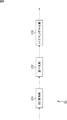
図1は、従来の画像処理システムの構成例を示している。この画像処理システム10は、符号化されたデジタル画像信号である符号化デジタル画像信号Vcdを処理し、アナログ画像信号Vanを出力する再生装置11、この再生装置11から出力されるアナログ画像信号Vanによる画像を表示する表示装置12、並びに、再生装置11から出力されるアナログ画像信号Vanを符号化し、その符号化デジタル画像信号Vcdを記録媒体に記録する符号化装置13を有している。
FIG. 1 shows a configuration example of a conventional image processing system. The image processing system 10 processes an encoded digital image signal Vcd, which is an encoded digital image signal, and outputs an analog image signal Van, and an analog image signal Van output from the playback device 11. A
再生装置11は、復号部21およびD/A(Digital / Analog)変換部22(以下、D/A22と称する)を有している。復号部21は、図示しない光ディスク等の記録媒体から読み出された符号化デジタル画像信号Vcdを復号する。D/A22は、その復号されて得られたデジタル画像信号Vdgをアナログ画像信号Vanに変換する。
The playback device 11 includes a
再生装置11は、このアナログ画像信号Vanを表示装置12および符号化装置13に供給する。
The playback device 11 supplies the analog image signal Van to the
表示装置12は、ディスプレイ23を有している。ディスプレイ23は、例えばCRT(Cathode-Ray Tube)ディスプレイや、LCD(Liquid Crystal Display)等により構成される。表示装置12は、再生装置11より供給されるアナログ画像信号Vanをこのディスプレイ23に表示する。
The
符号化装置13は、A/D(Analog / Digital)変換部24(以下、A/D24と称する)、符号化部25、および記録部26を有している。A/D24は、再生装置11より供給されるアナログ画像信号Vanをデジタル信号に変換しデジタル画像信号Vdgを生成する。符号化部25は、そのデジタル画像信号Vdgを符号化し、符号化デジタル画像信号Vcdを生成する。記録部26は、例えばハードディスク、半導体メモリ、若しくは、DVD(Digital Versatile Disc)ドライブ等を有しており、符号化部25において生成された符号化デジタル画像信号Vcdをそれらの記録媒体に記録する。
The
つまり、画像処理システム10は、符号化デジタル画像信号Vcdを受け付け、その符号化デジタル画像信号Vcdからアナログ画像信号Vanを再生し、画像を表示するか、若しくは、再生されたアナログ画像信号Vanを再度符号化し、符号化デジタル画像信号Vcdを記録媒体に記録するシステムである。 That is, the image processing system 10 receives the encoded digital image signal Vcd, reproduces the analog image signal Van from the encoded digital image signal Vcd, displays an image, or regenerates the reproduced analog image signal Van. This is a system for encoding and recording an encoded digital image signal Vcd on a recording medium.
このように、画像処理システム10は、アナログ画像信号Vanを生成するため、そのアナログ画像信号Vanを利用した不正な複製(不正コピー)に利用される恐れがあった。 As described above, since the image processing system 10 generates the analog image signal Van, there is a possibility that the image processing system 10 may be used for unauthorized duplication (illegal copy) using the analog image signal Van.
つまり、アナログ画像信号Vanにおいては、デジタル著作権保護機能は作用しないため、符号化装置13は、アナログ画像信号Vanをデジタル化して符号化することにより、元の符号化デジタル画像信号Vcdを再現して記録することができる。
That is, since the digital copyright protection function does not operate on the analog image signal Van, the
従来、このようなアナログ画像信号Vanを利用した不正コピーを防止するために、著作権保護がなされている場合には、アナログ画像信号Vanをスクランブル処理したり、あるいはアナログ画像信号Vanの出力を禁止したりすることが提案されている(例えば、特許文献1参照)。 Conventionally, in order to prevent unauthorized copying using such an analog image signal Van, when copyright protection is provided, the analog image signal Van is scrambled or the analog image signal Van is prohibited from being output. Has been proposed (see, for example, Patent Document 1).
また、再生装置11または符号化装置13のいずれか一方もしくは両方に雑音情報発生部を設け、デジタルビデオデータに1回の処理では画像再生時に識別できない程度の雑音情報を埋め込むことにより、コピー自体は可能であるが、複数回繰り返すと画像が著しく劣化し、これによって実質的にコピーの回数を制限するデジタルビデオ装置が提案されている(例えば、特許文献2参照)。
In addition, by providing a noise information generation unit in one or both of the playback device 11 and the
しかしながら、例えば、上述した特許文献1のように、再生装置11が、アナログ画像信号Vanをスクランブル処理して出力したり、あるいはアナログ画像信号Vanの出力を禁止したりすることで、不正コピーを防止する方法の場合、表示装置12がディスプレイ23に正常な画像が表示させることができないという問題がある。
However, for example, as in
例えば、再生装置11が、アナログ画像信号Vanをスクランブル処理して出力する場合、そのスクランブル機能に対応し、正常な画像を表示させる機能を表示装置12に設ける必要がある。
For example, when the playback device 11 scrambles and outputs the analog image signal Van, it is necessary to provide the
また、上述した特許文献2のように、再生側の復号部または記録側の符号化部等でデジタル画像信号に雑音情報を埋め込むものでは、雑音情報発生部とこれを埋め込むための回路が必要となり、回路規模が増大するという問題がある。
In addition, as in
そこで、画像が表示されなくなることや回路規模の増大を招くこと等の不都合を発生することなく、アナログ画像信号を利用した不正コピーを防止する手法が、本出願人により提案されている(例えば、特許文献3参照)。 Therefore, a method for preventing unauthorized copying using an analog image signal without causing inconvenience such as an image not being displayed or an increase in circuit scale has been proposed by the present applicant (for example, (See Patent Document 3).
上述した特許文献3に記載の手法では、アナログ画像信号をA/D変換することにより得られるデジタル画像信号の位相ズレ等のアナログノイズに着目し、そのデジタル画像信号に対してアナログノイズに着目した符号化を行うことによってコピー前の画像の質を落とさずに、良好な質を維持したままでのコピーを不可能とし、これによりアナログ画像信号を利用した不正コピーを防止するが、デジタルコンテンツの流通が一般的になっている近年においては、上述のように不正コピーを防止するための別の手法の提案が要請されている。
In the method described in
本発明はこのような状況に鑑みてなされたものであり、アナログ信号を利用したコンテンツデータの不正な複製を抑制することができるようにするものである。 The present invention has been made in view of such a situation, and makes it possible to suppress unauthorized duplication of content data using an analog signal.
本発明の符号化装置は、アナログ歪を含む入力画像データを符号化する符号化装置であって、前記入力画像データの各フレーム画像を複数のブロックに分割してブロック化するブロック化手段と、前記ブロック化手段によりブロック化されて得られた各ブロックの周縁部の複数の画素を特定画素とし、前記特定画素に限らない全画素群の中で互いに隣接する特定画素群をグループとし、前記グループ毎に前記特定画素の画素値をベクトル量子化するベクトル量子化手段と、各ブロックにおいて、前記ベクトル量子化手段によりベクトル量子化された前記特定画素の画素値に基づいて、前記ブロック内の前記特定画素以外の各画素の画素値を予測する予測手段と、前記ブロック内の前記特定画素以外の各画素について、前記予測手段により予測された画素値である予測画素値と前記入力画像データ中の画素値との差分を算出する差分算出手段と、前記差分算出手段により得られた前記差分を前記ブロック毎に符号化する差分符号化手段とを備える。 An encoding apparatus according to the present invention is an encoding apparatus that encodes input image data including analog distortion, and includes a blocking unit that divides each frame image of the input image data into a plurality of blocks, A plurality of pixels at the peripheral edge of each block obtained by blocking by the blocking unit is a specific pixel, a group of specific pixels adjacent to each other among all pixel groups not limited to the specific pixel, and the group Vector quantization means for vector-quantizing the pixel value of the specific pixel every time, and in each block, the specific value in the block based on the pixel value of the specific pixel vector-quantized by the vector quantization means Prediction means for predicting the pixel value of each pixel other than the pixel, and prediction by the prediction means for each pixel other than the specific pixel in the block A difference calculating unit that calculates a difference between a predicted pixel value that is a pixel value obtained and a pixel value in the input image data, and differential encoding that encodes the difference obtained by the difference calculating unit for each block Means.
前記ベクトル量子化手段は、各ブロックの4隅の画素を特定画素とすることができる。 It said vector quantization means may be a specific pixel of the four corners of the pixels in each block.
前記予測手段は、前記ブロック内の前記特定画素以外の各画素の画素値を、各特定画素の画素値と、各特定画素までの距離とを用いて予測することができる。
前記予測手段は、前記ブロック内の前記特定画素以外の各画素の画素値を、前記画素に最も近い前記特定画素の画素値に設定することができる。
It said predicting means, the pixel values of the pixels other than the specific pixel in the block, the pixel values of the specific pixel, it is the this predicted using the distance to each particular pixel.
The prediction means can set the pixel value of each pixel other than the specific pixel in the block to the pixel value of the specific pixel closest to the pixel.
前記差分算出手段は、さらに特定画素の差分を「0」に設定し、差分符号化手段は、特定画素を含むブロック内の全ての画素の差分を符号化するようにすることができる。 The difference calculation unit may further set the difference of the specific pixel to “0”, and the difference encoding unit may encode the difference of all the pixels in the block including the specific pixel.
前記差分符号化手段は、差分算出手段により得られた差分を直交変換する直交変換手段と、直交変換手段により差分が直交変換されて得られた係数データを量子化する量子化手段と、量子化手段により係数データが量子化されて得られた量子化係数データを可変長符号化する可変長符号化手段とを備えるようにすることができる。 The difference encoding means includes an orthogonal transform means for orthogonally transforming the difference obtained by the difference calculating means, a quantization means for quantizing the coefficient data obtained by orthogonally transforming the difference by the orthogonal transform means, and quantization And variable length coding means for variable length coding the quantized coefficient data obtained by quantizing the coefficient data by the means.
前記直交変換手段は差分を離散サイン変換するようにすることができる。 The orthogonal transform means may perform discrete sine transform on the difference.
前記ベクトル量子化手段において選択された、特定画素のグループのベクトル量子化結果に対応するコードに関する情報である選択コード情報、および、差分符号化手段により差分が符号化されて得られた符号化データを符号化装置の外部に出力する出力手段をさらに備えるようにすることができる。 Selection code information which is information related to a code corresponding to a vector quantization result of a group of specific pixels selected by the vector quantization means, and encoded data obtained by encoding a difference by the difference encoding means Can be further provided with output means for outputting the signal to the outside of the encoding device.
アナログ信号の入力画像データに対して、アナログ成分に対するノイズ成分であるアナログノイズを付加するノイズ付加手段と、ノイズ付加手段によりアナログノイズが付加されたアナログ信号の入力画像データをA/D変換し、デジタルデータの入力画像データを得るA/D変換手段とをさらに備え、ブロック化手段は、A/D変換手段によりA/D変換されて得られたデジタルデータの入力画像データの各フレーム画像を複数のブロックに分割してブロック化することができる。 A / D conversion of analog signal input image data to which analog noise is added by noise adding means for adding analog noise, which is a noise component to the analog component, to analog image input image data, A / D conversion means for obtaining input image data of digital data, and the blocking means includes a plurality of frame images of the input image data of digital data obtained by A / D conversion by the A / D conversion means. it can be blocked by dividing the block.
本発明の符号化方法は、アナログ歪を含む入力画像データを符号化する符号化装置の符号化方法であって、前記符号化装置のブロック化手段が、前記入力画像データの各フレーム画像を複数のブロックに分割してブロック化し、前記符号化装置のベクトル量子化手段が、ブロック化されて得られた各ブロックの周縁部の複数の画素を特定画素とし、前記特定画素に限らない全画素群の中で互いに隣接する特定画素群をグループとし、前記グループ毎に前記特定画素の画素値をベクトル量子化し、前記符号化装置の予測手段が、各ブロックにおいて、ベクトル量子化された前記特定画素の画素値に基づいて、前記ブロック内の前記特定画素以外の各画素の画素値を予測し、前記符号化装置の差分算出手段が、前記ブロック内の前記特定画素以外の各画素について、予測された画素値である予測画素値と前記入力画像データ中の画素値との差分を算出し、前記符号化装置の差分符号化手段が、得られた前記差分を前記ブロック毎に符号化する。 An encoding method according to the present invention is an encoding method of an encoding device that encodes input image data including analog distortion, and the blocker of the encoding device generates a plurality of frame images of the input image data. All the pixel groups that are not limited to the specific pixels, and the pixel quantization unit of the encoding device sets the plurality of pixels at the peripheral edge of each block obtained as a specific pixel. Specific pixel groups adjacent to each other in a group, the pixel value of the specific pixel is vector-quantized for each group, and the predicting means of the encoding device performs the vector quantization of the specific pixel in each block. Based on the pixel value, the pixel value of each pixel other than the specific pixel in the block is predicted, and the difference calculation unit of the encoding device is a unit other than the specific pixel in the block. For each pixel, a difference between a predicted pixel value that is a predicted pixel value and a pixel value in the input image data is calculated, and the difference encoding unit of the encoding device calculates the obtained difference for each block. Is encoded.
本発明の第1の記録媒体は、アナログ歪を含む入力画像データを符号化するコンピュータを、前記入力画像データの各フレーム画像を複数のブロックに分割してブロック化するブロック化手段と、前記ブロック化手段によりブロック化されて得られた各ブロックの周縁部の複数の画素を特定画素とし、前記特定画素に限らない全画素群の中で互いに隣接する特定画素群をグループとし、前記グループ毎に前記特定画素の画素値をベクトル量子化するベクトル量子化手段と、各ブロックにおいて、前記ベクトル量子化手段によりベクトル量子化された前記特定画素の画素値に基づいて、前記ブロック内の前記特定画素以外の各画素の画素値を予測する予測手段と、前記ブロック内の前記特定画素以外の各画素について、前記予測手段により予測された画素値である予測画素値と前記入力画像データ中の画素値との差分を算出する差分算出手段と、前記差分算出手段により得られた前記差分を前記ブロック毎に符号化する差分符号化手段として機能させるためのプログラムを記録している。 According to a first recording medium of the present invention, there is provided a blocking unit that blocks a computer that encodes input image data including analog distortion by dividing each frame image of the input image data into a plurality of blocks, and the block A plurality of pixels at the peripheral edge of each block obtained by making into a block by the converting means are specified pixels, and among all pixel groups not limited to the specified pixels, adjacent specific pixel groups are grouped, and for each group Vector quantization means for vector-quantizing the pixel value of the specific pixel, and, in each block, based on the pixel value of the specific pixel vector-quantized by the vector quantization means, other than the specific pixel in the block Prediction means for predicting the pixel value of each of the pixels, and prediction by the prediction means for each pixel other than the specific pixel in the block A difference calculating unit that calculates a difference between a predicted pixel value that is a pixel value obtained and a pixel value in the input image data, and differential encoding that encodes the difference obtained by the difference calculating unit for each block A program for functioning as a means is recorded.
本発明の第1のプログラムは、アナログ歪を含む入力画像データを符号化するコンピュータを、前記入力画像データの各フレーム画像を複数のブロックに分割してブロック化するブロック化手段と、前記ブロック化手段によりブロック化されて得られた各ブロックの周縁部の複数の画素を特定画素とし、前記特定画素に限らない全画素群の中で互いに隣接する特定画素群をグループとし、前記グループ毎に前記特定画素の画素値をベクトル量子化するベクトル量子化手段と、各ブロックにおいて、前記ベクトル量子化手段によりベクトル量子化された前記特定画素の画素値に基づいて、前記ブロック内の前記特定画素以外の各画素の画素値を予測する予測手段と、前記ブロック内の前記特定画素以外の各画素について、前記予測手段により予測された画素値である予測画素値と前記入力画像データ中の画素値との差分を算出する差分算出手段と、前記差分算出手段により得られた前記差分を前記ブロック毎に符号化する差分符号化手段として機能させる。 According to a first program of the present invention, there is provided a blocking unit that blocks a computer that encodes input image data including analog distortion by dividing each frame image of the input image data into a plurality of blocks, and the blocking A plurality of pixels at the peripheral edge of each block obtained by the block formation as a specific pixel, a specific pixel group adjacent to each other among all pixel groups not limited to the specific pixel as a group, and for each group Vector quantization means for vector-quantizing the pixel value of the specific pixel, and in each block, based on the pixel value of the specific pixel that has been vector quantized by the vector quantization means, other than the specific pixel in the block Prediction means for predicting the pixel value of each pixel, and each pixel other than the specific pixel in the block is predicted by the prediction means. A difference calculating unit that calculates a difference between a predicted pixel value that is a pixel value that has been generated and a pixel value in the input image data; and differential encoding that encodes the difference obtained by the difference calculating unit for each block It functions as a means.
本発明の復号装置は、アナログ歪を含む画像データが符号化装置によって符号化されて得られた符号化データを復号する復号装置であって、前記画像データの各フレーム画像の各ブロックの周縁部の複数の画素が特定画素とされ、前記特定画素に限らない全画素群の中で互いに隣接する特定画素群がグループとされ、前記グループ毎に前記特定画素の画素値がベクトル量子化され、各ブロックにおいてベクトル量子化された前記特定画素の画素値に基づいて前記ブロック内の前記特定画素以外の各画素の画素値が予測され、前記ブロック内の前記特定画素以外の各画素について予測画素値と前記画像データ中の画素値との差分が算出され、前記差分が前記ブロック毎に符号化された前記符号化データから、前記特定画素のベクトル量子化の結果として選択されたコードに関する情報である選択コード情報を分離する分離手段と、前記分離手段により前記符号化データから分離された前記選択コード情報を逆ベクトル量子化する逆ベクトル量子化手段と、前記逆ベクトル量子化手段により逆ベクトル量子化されて得られた前記特定画素の画素値を用いて、前記特定画素を含むブロック内の、前記特定画素以外の各画素の画素値を予測する予測手段と、前記分離手段により前記選択コード情報が分離された前記符号化データを復号する差分復号手段と、前記特定画素以外の各画素について、前記予測手段により得られた予測画素値と、前記差分復号手段により復号されて得られた差分とを加算する画素値加算手段とを備える。 The decoding device of the present invention is a decoding device that decodes encoded data obtained by encoding image data including analog distortion by an encoding device, and a peripheral portion of each block of each frame image of the image data A plurality of pixels as specific pixels, and among all pixel groups not limited to the specific pixels, adjacent specific pixel groups are grouped, and for each group, pixel values of the specific pixels are vector quantized, A pixel value of each pixel other than the specific pixel in the block is predicted based on a pixel value of the specific pixel vector-quantized in the block, and a predicted pixel value for each pixel other than the specific pixel in the block A difference with a pixel value in the image data is calculated, and the result of vector quantization of the specific pixel is obtained from the encoded data obtained by encoding the difference for each block. Separating means for separating selected code information, which is information relating to the code selected as: an inverse vector quantizing means for inverse vector quantizing the selected code information separated from the encoded data by the separating means; Prediction means for predicting the pixel value of each pixel other than the specific pixel in the block including the specific pixel, using the pixel value of the specific pixel obtained by inverse vector quantization by the vector quantization means; Differential decoding means for decoding the encoded data from which the selection code information has been separated by the separation means; prediction pixel values obtained by the prediction means for each pixel other than the specific pixel; and the difference decoding means Pixel value adding means for adding the difference obtained by decoding.
前記特定画素は、各ブロックの4隅の画素であるようにすることができる。 The specific pixels may be pixels at the four corners of each block.
前記画素値加算手段は、特定画素の差分を「0」に設定してから加算を行うようにすることができる。 The pixel value adding means may perform addition after setting a difference between specific pixels to “0”.
前記画素値加算手段は、加算結果として得られた各画素の入力画素値をブロック毎にラスター順に並び替えるようにすることができる。 The pixel value adding means can rearrange the input pixel values of each pixel obtained as an addition result in raster order for each block.
前記差分復号手段は、符号化データを可変長復号する可変長復号手段と、可変長復号手段により符号化データが可変長復号されて得られた量子化係数データを逆量子化する逆量子化手段と、逆量子化手段により量子化係数データが逆量子化されて得られた係数データを逆直交変換する逆直交変換手段とを備える。 The difference decoding means includes variable length decoding means for variable-length decoding the sign-coded data, inverse quantization of inverse quantizing the quantized coefficient data encoded data obtained by the variable length decoding by the variable length decoding unit means, Ru and an inverse orthogonal transform means for inverse orthogonal transform coefficient data obtained by the inverse quantization quantized coefficient data by the inverse quantization means.
前記直交変換手段は係数データを逆離散サイン変換するようにすることができる。 The orthogonal transform means may perform inverse discrete sine transform on the coefficient data.
前記画素値加算手段において得られた前記画素値により構成されるデジタル画像データをD/A変換し、アナログ信号に変換するD/A変換手段と、前記D/A変換手段により前記デジタル画像データがD/A変換されて得られた前記アナログ信号に対して、アナログ成分に対するノイズ成分であるアナログノイズを付加するノイズ付加手段と前記ノイズ付加手段により前記アナログノイズが付加された前記アナログ信号を出力する出力手段とをさらに備えることができる。 Digital image data constituted by the pixel values obtained by the pixel value adding means is D / A converted and converted into analog signals, and the digital image data is converted by the D / A conversion means. A noise adding means for adding analog noise, which is a noise component with respect to the analog component, to the analog signal obtained by D / A conversion, and the analog signal to which the analog noise is added by the noise adding means is output. Output means .
本発明の復号方法は、アナログ歪を含む画像データが符号化装置によって符号化されて得られた符号化データを復号する復号装置の復号方法であって、前記復号装置の分離手段が、前記画像データの各フレーム画像の各ブロックの周縁部の複数の画素が特定画素とされ、前記特定画素に限らない全画素群の中で互いに隣接する特定画素群がグループとされ、前記グループ毎に前記特定画素の画素値がベクトル量子化され、各ブロックにおいてベクトル量子化された前記特定画素の画素値に基づいて前記ブロック内の前記特定画素以外の各画素の画素値が予測され、前記ブロック内の前記特定画素以外の各画素について予測画素値と前記画像データ中の画素値との差分が算出され、前記差分が前記ブロック毎に符号化された前記符号化データから、前記特定画素のベクトル量子化の結果として選択されたコードに関する情報である選択コード情報を分離し、前記復号装置の逆ベクトル量子化手段が、前記符号化データから分離された前記選択コード情報を逆ベクトル量子化し、前記復号装置の予測手段が、逆ベクトル量子化されて得られた前記特定画素の画素値を用いて、前記特定画素を含むブロック内の、前記特定画素以外の各画素の画素値を予測し、前記復号装置の差分復号手段が、前記選択コード情報が分離された前記符号化データを復号し、前記復号装置の画素値加算手段が、前記特定画素以外の各画素について、得られた予測画素値と、復号されて得られた差分とを加算する。 The decoding method of the present invention is a decoding method of a decoding apparatus for decoding encoded data obtained by encoding image data including analog distortion by an encoding apparatus, wherein the separation means of the decoding apparatus includes the image A plurality of pixels at the peripheral edge of each block of each frame image of data is set as a specific pixel, and among all pixel groups not limited to the specific pixel, adjacent specific pixel groups are grouped, and the specific pixel group is specified for each group. The pixel value of the pixel is vector-quantized, and the pixel value of each pixel other than the specific pixel in the block is predicted based on the pixel value of the specific pixel vector-quantized in each block, and the pixel value in the block For each pixel other than the specific pixel, the difference between the predicted pixel value and the pixel value in the image data is calculated, and whether the difference is the encoded data encoded for each block , Separating selected code information that is information relating to a code selected as a result of vector quantization of the specific pixel, and the inverse vector quantization means of the decoding device converts the selected code information separated from the encoded data inverse vector quantization, prediction means of the decoding apparatus, using a pixel value of the specific pixel obtained by being inverse vector quantization, in the block including the specified pixel, a pixel of each pixel other than the specific pixel Predicting the value, the differential decoding means of the decoding device decodes the encoded data from which the selection code information is separated, and the pixel value adding means of the decoding device obtains each pixel other than the specific pixel. The obtained prediction pixel value and the difference obtained by decoding are added .
本発明の第2の記録媒体は、アナログ歪を含む画像データが符号化装置によって符号化されて得られた符号化データを復号するコンピュータを、前記画像データの各フレーム画像の各ブロックの周縁部の複数の画素が特定画素とされ、前記特定画素に限らない全画素群の中で互いに隣接する特定画素群がグループとされ、前記グループ毎に前記特定画素の画素値がベクトル量子化され、各ブロックにおいてベクトル量子化された前記特定画素の画素値に基づいて前記ブロック内の前記特定画素以外の各画素の画素値が予測され、前記ブロック内の前記特定画素以外の各画素について予測画素値と前記画像データ中の画素値との差分が算出され、前記差分が前記ブロック毎に符号化された前記符号化データから、前記特定画素のベクトル量子化の結果として選択されたコードに関する情報である選択コード情報を分離する分離手段と、前記分離手段により前記符号化データから分離された前記選択コード情報を逆ベクトル量子化する逆ベクトル量子化手段と、前記逆ベクトル量子化手段により逆ベクトル量子化されて得られた前記特定画素の画素値を用いて、前記特定画素を含むブロック内の、前記特定画素以外の各画素の画素値を予測する予測手段と、前記分離手段により前記選択コード情報が分離された前記符号化データを復号する差分復号手段と、前記特定画素以外の各画素について、前記予測手段により得られた予測画素値と、前記差分復号手段により復号されて得られた差分とを加算する画素値加算手段として機能させるためのプログラムを記録している。 According to a second recording medium of the present invention, there is provided a computer for decoding encoded data obtained by encoding image data including analog distortion by an encoding device, and a peripheral portion of each block of each frame image of the image data. A plurality of pixels as specific pixels, and among all pixel groups not limited to the specific pixels, adjacent specific pixel groups are grouped, and for each group, pixel values of the specific pixels are vector quantized, A pixel value of each pixel other than the specific pixel in the block is predicted based on a pixel value of the specific pixel vector-quantized in the block, and a predicted pixel value for each pixel other than the specific pixel in the block A difference from a pixel value in the image data is calculated, and the vector quantization of the specific pixel is performed from the encoded data in which the difference is encoded for each block. Separation means for separating selected code information that is information relating to the selected code as a result, inverse vector quantization means for inverse vector quantization of the selected code information separated from the encoded data by the separation means, Prediction means for predicting the pixel value of each pixel other than the specific pixel in the block including the specific pixel, using the pixel value of the specific pixel obtained by inverse vector quantization by the inverse vector quantization means; Differential decoding means for decoding the encoded data from which the selection code information has been separated by the separation means; a predicted pixel value obtained by the prediction means for each pixel other than the specific pixel; and the differential decoding means The program for functioning as a pixel value addition means which adds the difference obtained by decoding is recorded.
本発明の第2のプログラムは、アナログ歪を含む画像データが符号化装置によって符号化されて得られた符号化データを復号するコンピュータを、前記画像データの各フレーム画像の各ブロックの周縁部の複数の画素が特定画素とされ、前記特定画素に限らない全画素群の中で互いに隣接する特定画素群がグループとされ、前記グループ毎に前記特定画素の画素値がベクトル量子化され、各ブロックにおいてベクトル量子化された前記特定画素の画素値に基づいて前記ブロック内の前記特定画素以外の各画素の画素値が予測され、前記ブロック内の前記特定画素以外の各画素について予測画素値と前記画像データ中の画素値との差分が算出され、前記差分が前記ブロック毎に符号化された前記符号化データから、前記特定画素のベクトル量子化の結果として選択されたコードに関する情報である選択コード情報を分離する分離手段と、前記分離手段により前記符号化データから分離された前記選択コード情報を逆ベクトル量子化する逆ベクトル量子化手段と、前記逆ベクトル量子化手段により逆ベクトル量子化されて得られた前記特定画素の画素値を用いて、前記特定画素を含むブロック内の、前記特定画素以外の各画素の画素値を予測する予測手段と、前記分離手段により前記選択コード情報が分離された前記符号化データを復号する差分復号手段と、前記特定画素以外の各画素について、前記予測手段により得られた予測画素値と、前記差分復号手段により復号されて得られた差分とを加算する画素値加算手段として機能させる。 According to a second program of the present invention, a computer that decodes encoded data obtained by encoding image data including analog distortion by an encoding device is provided on a peripheral portion of each block of each frame image of the image data. A plurality of pixels are specified pixels, a specified pixel group adjacent to each other among all pixel groups not limited to the specified pixel is grouped, and the pixel value of the specified pixel is vector-quantized for each group, The pixel value of each pixel other than the specific pixel in the block is predicted based on the pixel value of the specific pixel that is vector quantized in step, and the predicted pixel value and the pixel value for each pixel other than the specific pixel in the block A difference from a pixel value in the image data is calculated, and from the encoded data obtained by encoding the difference for each block, a vector quantum of the specific pixel is calculated. Separating means for separating selected code information that is information relating to the code selected as a result of the above, and inverse vector quantizing means for inverse vector quantizing the selected code information separated from the encoded data by the separating means; Prediction means for predicting the pixel value of each pixel other than the specific pixel in the block including the specific pixel, using the pixel value of the specific pixel obtained by inverse vector quantization by the inverse vector quantization means Differential decoding means for decoding the encoded data from which the selection code information has been separated by the separation means, predicted pixel values obtained by the prediction means for each pixel other than the specific pixel, and the differential decoding It is made to function as a pixel value addition means which adds the difference obtained by decoding by the means.
本発明の第1の情報処理システムは、符号化部、復号部とを有し、アナログ歪を含む画像データに対して符号化処理および復号処理を繰り返すと前記画像データが劣化するような情報処理システムにおいて、前記符号化部は、前記画像データの各フレーム画像を複数のブロックに分割してブロック化するブロック化手段と、前記ブロック化手段によりブロック化されて得られた各ブロックの周縁部の複数の画素を特定画素とし、前記特定画素に限らない全画素群の中で互いに隣接する特定画素群をグループとし、前記グループ毎に前記特定画素の画素値をベクトル量子化するベクトル量子化手段と、各ブロックにおいて、前記ベクトル量子化手段によりベクトル量子化された前記特定画素の画素値に基づいて、前記ブロック内の前記特定画素以外の各画素の画素値を予測する予測手段と、前記ブロック内の前記特定画素以外の各画素について、前記予測手段により予測された画素値である予測画素値と前記画像データ中の画素値との差分を算出する差分算出手段と、前記差分算出手段により得られた前記差分を前記ブロック毎に符号化する差分符号化手段とを備える。 The first information processing system of the present invention includes an encoding unit and a decoding unit, and information processing that degrades the image data when the encoding process and the decoding process are repeated for image data including analog distortion. In the system, the encoding unit includes a block unit that divides each frame image of the image data into a plurality of blocks, and a peripheral portion of each block obtained by the block unit. A vector quantizing unit that sets a plurality of pixels as specific pixels, groups specific pixel groups adjacent to each other among all pixel groups not limited to the specific pixels, and vector-quantizes pixel values of the specific pixels for each group; In each block, based on the pixel value of the specific pixel vector-quantized by the vector quantization means, the specific pixel in the block A prediction unit that predicts a pixel value of each pixel outside, a predicted pixel value that is a pixel value predicted by the prediction unit for each pixel other than the specific pixel in the block, and a pixel value in the image data Difference calculation means for calculating the difference between the difference calculation means and difference encoding means for encoding the difference obtained by the difference calculation means for each block.
本発明の第2の情報処理システムは、符号化部、復号部とを有し、アナログ歪を含む画像データに対して符号化処理および復号処理を繰り返すと前記画像データが劣化するような情報処理システムにおいて、前記復号部は、前記画像データの各フレーム画像の各ブロックの周縁部の複数の画素が特定画素とされ、前記特定画素に限らない全画素群の中で互いに隣接する特定画素群がグループとされ、前記グループ毎に前記特定画素の画素値がベクトル量子化され、各ブロックにおいてベクトル量子化された前記特定画素の画素値に基づいて前記ブロック内の前記特定画素以外の各画素の画素値が予測され、前記ブロック内の前記特定画素以外の各画素について予測画素値と前記画像データ中の画素値との差分が算出され、前記差分が前記ブロック毎に符号化された前記符号化データから、前記特定画素のベクトル量子化の結果として選択されたコードに関する情報である選択コード情報を分離する分離手段と、前記分離手段により前記符号化データから分離された前記選択コード情報を逆ベクトル量子化する逆ベクトル量子化手段と、前記逆ベクトル量子化手段により逆ベクトル量子化されて得られた前記特定画素の画素値を用いて、前記特定画素を含むブロック内の、前記特定画素以外の各画素の画素値を予測する予測手段と、前記分離手段により前記選択コード情報が分離された前記符号化データを復号する差分復号手段と、前記特定画素以外の各画素について、前記予測手段により得られた予測画素値と、前記差分復号手段により復号されて得られた差分とを加算する画素値加算手段とを備える。 A second information processing system according to the present invention includes an encoding unit and a decoding unit, and information processing in which the image data deteriorates when the encoding process and the decoding process are repeated for image data including analog distortion. In the system, the decoding unit includes a plurality of pixels at a peripheral portion of each block of each frame image of the image data as a specific pixel, and a specific pixel group adjacent to each other among all the pixel groups not limited to the specific pixel. A pixel value of each pixel other than the specific pixel in the block based on the pixel value of the specific pixel that is group-quantized, and the pixel value of the specific pixel is vector-quantized for each group A value is predicted, a difference between the predicted pixel value and a pixel value in the image data is calculated for each pixel other than the specific pixel in the block, and the difference is Separation means for separating selected code information, which is information relating to a code selected as a result of vector quantization of the specific pixel, from the encoded data encoded for each block, and from the encoded data by the separation means Inverse vector quantization means for performing inverse vector quantization on the separated selection code information, and using the pixel value of the specific pixel obtained by inverse vector quantization by the inverse vector quantization means, A prediction unit that predicts a pixel value of each pixel other than the specific pixel in a block including the difference decoding unit that decodes the encoded data from which the selection code information is separated by the separation unit; For each pixel, a pixel value that adds the predicted pixel value obtained by the predicting means and the difference obtained by decoding by the differential decoding means And a calculation means.
本発明の符号化装置および方法、第1の記録媒体、並びに第1のプログラムにおいては、入力画像データの各フレーム画像が複数のブロックに分割してブロック化され、ブロック化されて得られた各ブロックの周縁部の複数の画素が特定画素とされ、特定画素に限らない全画素群の中で互いに隣接する特定画素群がグループとされ、グループ毎に特定画素の画素値がベクトル量子化され、各ブロックにおいて、ベクトル量子化された特定画素の画素値に基づいて、ブロック内の特定画素以外の各画素の画素値が予測され、ブロック内の特定画素以外の各画素について、予測された画素値である予測画素値と入力画像データ中の画素値との差分が算出され、得られた差分がブロック毎に符号化される。 In the encoding apparatus and method, the first recording medium, and the first program according to the present invention, each frame image of the input image data is divided into a plurality of blocks, and each block image is obtained by being blocked. A plurality of pixels at the peripheral edge of the block are specified pixels, a specific pixel group adjacent to each other among all pixel groups not limited to a specific pixel is grouped, and the pixel value of the specific pixel is vector quantized for each group, In each block, the pixel value of each pixel other than the specific pixel in the block is predicted based on the pixel value of the specific pixel subjected to vector quantization, and the predicted pixel value for each pixel other than the specific pixel in the block The difference between the predicted pixel value and the pixel value in the input image data is calculated, and the obtained difference is encoded for each block.
本発明の復号装置および方法、第2の記録媒体、並びに第2のプログラムにおいては、画像データの各フレーム画像の各ブロックの周縁部の複数の画素が特定画素とされ、特定画素に限らない全画素群の中で互いに隣接する特定画素群がグループとされ、グループ毎に特定画素の画素値がベクトル量子化され、各ブロックにおいてベクトル量子化された特定画素の画素値に基づいてブロック内の特定画素以外の各画素の画素値が予測され、ブロック内の特定画素以外の各画素について予測画素値と画像データ中の画素値との差分が算出され、差分がブロック毎に符号化された符号化データから、特定画素のベクトル量子化の結果として選択されたコードに関する情報である選択コード情報が分離され、符号化データから分離された選択コード情報が逆ベクトル量子化され、逆ベクトル量子化されて得られた特定画素の画素値が用いられて、特定画素を含むブロック内の、特定画素以外の各画素の画素値が予測され、選択コード情報が分離された符号化データが復号され、特定画素以外の各画素について、得られた予測画素値と、復号されて得られた差分とが加算される。 In the decoding apparatus and method, the second recording medium, and the second program of the present invention, a plurality of pixels at the peripheral edge of each block of each frame image of the image data are set as specific pixels, and are not limited to specific pixels. Specific pixel groups adjacent to each other in the pixel group are grouped, and the pixel value of the specific pixel is vector-quantized for each group, and the specific value in the block is determined based on the pixel value of the specific pixel vector-quantized in each block. Encoding in which the pixel value of each pixel other than the pixel is predicted, the difference between the predicted pixel value and the pixel value in the image data is calculated for each pixel other than the specific pixel in the block, and the difference is encoded for each block Selection code information that is information related to a code selected as a result of vector quantization of a specific pixel is separated from the data, and the selection code is separated from the encoded data. Information is subjected to inverse vector quantization, and the pixel value of a specific pixel obtained by inverse vector quantization is used to predict the pixel value of each pixel other than the specific pixel in the block including the specific pixel. The encoded data from which the information is separated is decoded, and for each pixel other than the specific pixel, the obtained predicted pixel value and the difference obtained by decoding are added.
本発明の第1の情報処理システムにおいては、符号化部により、画像データの各フレーム画像が複数のブロックに分割してブロック化され、ブロック化されて得られた各ブロックの周縁部の複数の画素が特定画素とされ、特定画素に限らない全画素群の中で互いに隣接する特定画素群がグループとされ、グループ毎に特定画素の画素値がベクトル量子化され、各ブロックにおいて、ベクトル量子化された特定画素の画素値に基づいて、ブロック内の特定画素以外の各画素の画素値が予測され、ブロック内の特定画素以外の各画素について、予測された画素値である予測画素値と画像データ中の画素値との差分が算出され、得られた差分がブロック毎に符号化される。 In the first information processing system of the present invention, the encoding unit divides each frame image of the image data into a plurality of blocks and blocks the plurality of blocks, and a plurality of peripheral portions of each block obtained by the blocking are obtained. A pixel is a specific pixel, and among all pixel groups that are not limited to a specific pixel, a specific pixel group adjacent to each other is grouped, and the pixel value of the specific pixel is vector-quantized for each group. Based on the pixel value of the specified pixel, the pixel value of each pixel other than the specific pixel in the block is predicted, and for each pixel other than the specific pixel in the block, a predicted pixel value that is a predicted pixel value and an image The difference with the pixel value in the data is calculated, and the obtained difference is encoded for each block.
本発明の第2の情報処理システムにおいては、復号部により、画像データの各フレーム画像の各ブロックの周縁部の複数の画素が特定画素とされ、特定画素に限らない全画素群の中で互いに隣接する特定画素群がグループとされ、グループ毎に特定画素の画素値がベクトル量子化され、各ブロックにおいてベクトル量子化された特定画素の画素値に基づいてブロック内の特定画素以外の各画素の画素値が予測され、ブロック内の特定画素以外の各画素について予測画素値と画像データ中の画素値との差分が算出され、差分がブロック毎に符号化された符号化データから、特定画素のベクトル量子化の結果として選択されたコードに関する情報である選択コード情報が分離され、符号化データから分離された選択コード情報が逆ベクトル量子化され、逆ベクトル量子化されて得られた特定画素の画素値が用いられて、特定画素を含むブロック内の、特定画素以外の各画素の画素値が予測され、選択コード情報が分離された符号化データが復号され、特定画素以外の各画素について、得られた予測画素値と、復号されて得られた差分とが加算される。 In the second information processing system of the present invention, a plurality of pixels at the peripheral edge of each block of each frame image of the image data are set as specific pixels by the decoding unit , and each other in all pixel groups not limited to the specific pixels. Adjacent specific pixel groups are grouped, and the pixel value of the specific pixel is vector-quantized for each group, and each pixel other than the specific pixel in the block is based on the pixel value of the specific pixel vector-quantized in each block. The pixel value is predicted, the difference between the predicted pixel value and the pixel value in the image data is calculated for each pixel other than the specific pixel in the block, and the specific pixel is calculated from the encoded data obtained by encoding the difference for each block. The selected code information, which is information about the code selected as a result of vector quantization, is separated, and the selected code information separated from the encoded data is inverse vector quantized. The pixel value of the specific pixel obtained by inverse vector quantization is used to predict the pixel value of each pixel other than the specific pixel in the block including the specific pixel, and the selection code information is separated. The decoded data is decoded, and for each pixel other than the specific pixel, the obtained predicted pixel value and the difference obtained by decoding are added.
本発明によれば、アナログ信号を利用したコンテンツデータの不正な複製を抑制することができる。特に、画像が表示されなくなる、回路規模の増大を招く等の不都合を発生させずに、2回目以降の符号化処理および復号処理では画像データを著しく劣化させ、アナログ信号を利用した不正コピーを抑制することができる。 According to the present invention, unauthorized duplication of content data using an analog signal can be suppressed. In particular, without causing inconveniences such as no image being displayed or an increase in circuit scale, the second and subsequent encoding and decoding processes significantly degrade image data and suppress unauthorized copying using analog signals. can do.
以下、本発明の実施の形態について図を参照して説明する。 Hereinafter, embodiments of the present invention will be described with reference to the drawings.
図2は、本発明を適用した画像処理システムの構成例を示す図である。 FIG. 2 is a diagram illustrating a configuration example of an image processing system to which the present invention is applied.
図2に示される画像処理システム30は、再生装置31、表示装置32、および符号化装置33を有しており、符号化されたデジタル画像信号を処理してアナログ画像信号を生成し、その画像を表示したり、そのアナログ画像信号を再度符号化して符号化デジタル画像信号を記録媒体に記録したりするシステムである。
An image processing system 30 shown in FIG. 2 includes a
再生装置31は、復号部41およびD/A(Digital / Analog)変換部42(以下、D/A42と称する)を有している。復号部41は、図示しない光ディスク等の記録媒体から再生された符号化デジタル画像信号Vcd0を復号し、デジタル画像信号Vdg0を生成する。この復号部41の詳細については後述する。D/A42は、そのデジタル画像信号Vdg0をアナログ信号に変換し、アナログ画像信号Van1を生成する。再生装置31は、そのアナログ画像信号Van1を表示装置32および符号化装置33に供給する。
The
なお、このアナログ画像信号Van1は、アナログ歪みを伴うものである。このアナログ歪みには、例えば、D/A42でアナログ信号に変換する際に高周波成分が除去されることで生じる歪み、D/A42でアナログ信号に変換する際に信号の位相がずれることで生じる歪み等が含まれる。このアナログ歪みによる画像の劣化を評価する方法として、例えば、S/N(Signal-to-Noise)評価や視覚評価(視覚的劣化の評価)等がある。このアナログ歪みは、実際の装置において通常起こりうる自然発生的なものであっても良いし、後述するように意図的に生じさせたものであってもよい。
This analog image signal Van1 is accompanied by analog distortion. The analog distortion includes, for example, distortion caused by removing a high frequency component when converted to an analog signal by the D /
表示装置32は、例えばCRT(Cathode Ray Tube)ディスプレイやLCD(Liquid Crystal Display)等からなるディスプレイ43を有しており、再生装置31が出力するアナログ画像信号Van1を取得すると、その画像をディスプレイ43に表示する。
The
符号化装置33は、A/D(Analog / Digital)変換部44(以下、A/D44と称する)、符号化部45、記録部46、復号部41、D/A42、およびディスプレイ43を有している。符号化装置33は、A/D44において再生装置31より供給されたアナログ画像信号Van1をデジタル画像信号Vdg1に変換した後、符号化部45においてそれを符号化し、記録部46においてその符号化デジタル画像信号Vcd1を記録媒体に記録する。また、符号化装置33は、復号部41において符号化デジタル画像信号Vcd1を再度復号し、復号したデジタル画像信号Vdg2をD/A42においてD/A変換してアナログ画像信号Van2を生成すると、その画像をディスプレイ43に表示する。
The
A/D44は、再生装置31が出力したアナログ画像信号Van1をデジタル信号に変換し、デジタル画像信号Vdg1を生成する。符号化部45は、そのデジタル画像信号Vdg1を符号化し、符号化デジタル画像信号Vcd1を生成する。この符号化部45の詳細については後述する。記録部46は、例えばハードディスク、半導体メモリ、若しくは、DVD(Digital Versatile Disc)ドライブ等を有しており、符号化部45において生成された符号化デジタル画像信号Vcd1をそれらの記録媒体に記録する。
The A /
また、この符号化装置33の復号部41は、符号化部45において生成された符号化デジタル画像信号Vcd1を復号し、デジタル画像信号Vdg2を生成する。符号化装置33のD/A42は、符号化装置33の復号部41が復号したデジタル画像信号Vdg2をアナログ画像信号Van2に変換する。符号化装置33のディスプレイ43は、そのアナログ画像信号Van2の画像を表示する。
The
なお、詳細については後述するが、符号化装置33の符号化部45は、アナログ画像信号Van1に含まれるアナログ歪みを利用することにより、画像信号のコンテンツとしての品質(画像の画質)を大幅に劣化させて符号化する。また、再生装置31や符号化装置33の復号部41もこの符号化部45に対応する復号方法で入力された符号化デジタル画像信号を復号する。
Although details will be described later, the
つまり、図2において、アナログ画像信号Van、デジタル画像信号Vdg、および符号化デジタル画像信号Vcdのそれぞれに対して、各信号の位置により識別用の番号を付してあるが、この番号は、劣化等によってその信号が他の同種の信号と異なる内容の信号であることを示している。例えば、アナログ画像信号Vanの場合、符号化装置33のD/A42が出力するアナログ画像信号Van2は、アナログ歪みを利用して画質を劣化させながら符号化する符号化部45およびその符号化装置45に対応する復号部46を介した後の信号を用いて生成されており、再生装置31のD/A42が出力するアナログ画像信号Van1より劣化した画像情報の信号である。同様に、デジタル画像信号Vdg2の画像もデジタル画像信号Vdg1の画像より劣化しており、そのデジタル画像信号Vdg1の画像もデジタル画像信号Vdg0の画像より劣化している。符号化デジタル画像信号Vcdの場合も同様であり、符号化デジタル画像信号Vcd0よりも符号化デジタル画像信号Vcd1の方が、画像が劣化している。
That is, in FIG. 2, identification numbers are assigned to the analog image signal Van, the digital image signal Vdg, and the encoded digital image signal Vcd depending on the position of each signal. This indicates that the signal is different from other similar signals. For example, in the case of the analog image signal Van, the analog image signal Van2 output from the D /
このように画像処理システム30は、再生装置31がアナログ画像信号Van1を出力し、表示装置32がその画像を表示するが、そのアナログ画像信号Van1を利用して符号化装置33が画像データを複製する場合、その画像を劣化させるので、アナログ画像信号Vanを利用した複製を抑制することができる。
As described above, in the image processing system 30, the
次に、各部の詳細について説明する。最初に、符号化装置33の符号化部45について説明する。図3は、図2の符号化部45の詳細な構成例を説明するブロック図である。符号化部45は、ブロック化部61、ベクトル量子化(VQ)部62(以下、VQ部62と称する)、予測部63、残差算出部64、残差符号化部65、および出力部66を有している。
Next, the detail of each part is demonstrated. First, the
ブロック化部61は、入力されたデジタル画像信号Vdg1に含まれるフレーム画像データを所定のサイズのブロックに分割する。ブロック化部61は、フレーム画像データ(有効画面の画像信号)を、例えば、図4に示されるように、8画素×8画素の大きさのブロック(BL)に分割する。なお、図4において、白丸はブロックを構成する画素データを示しており、水平方向および垂直方向の直線は、フレーム画像データの一部が水平方向に3ブロック、垂直方向に2ブロック(BL71乃至BL76の合計6ブロック)に分割されている様子を示している。この図4は、フレーム画像データをブロック化する様子を示す模式図であり、フレーム画像データの実際の内容を示すものではない。図3のブロック化部61は、このようにブロック化した画像データをブロック毎にVQ部62に供給する。
The blocking
VQ部62は、ブロック化部61において得られる各ブロックの周縁部の複数の画素を特定画素として特定し、各フレーム画像内に存在する複数の特定画素を、その位置によって所定の範囲毎にグループ化し、そのグループ毎に特定画素の画素値をベクトル量子化する。図5にVQ部62の詳細を示す。図5において、VQ部62は、特定画素データ抽出部81、ベクトル生成部82、画素パターン別コードブック83、およびVQコード決定部84を有している。
The
特定画素データ抽出部81は、ブロック化部61より供給されるブロック毎の画素データから予め定められている特定の画素の画素データを抽出し、それをベクトル生成部82に供給する。例えば、特定画素データ抽出部81は、図6に示されるように、各ブロックの4隅の画素を特定画素とし、その画素データをベクトル生成部82に供給する。図6の場合、特定画素データ抽出部81は、BL71に対して、画素91A乃至画素91Dを特定画素として抽出し、BL72に対して、画素92A乃至画素92Dを特定画素として抽出し、BL73に対して、画素93A乃至画素93Dを特定画素として抽出し、BL74に対して、画素94A乃至画素94Dを特定画素として抽出し、BL75に対して、画素95A乃至画素95Dを特定画素として抽出し、BL76に対して、画素96A乃至画素96Dを特定画素として抽出している。特定画素データ抽出部81は、他のブロックについても同様に特定画素を抽出する。
The specific pixel
なお、この特定画素は、ブロックのどの位置の画素であってもよいが、後述するように効率よくアナログ信号の位相ずれを利用して画質を劣化させるためには、各ブロックの周縁部の複数の画素(例えば、各ブロックの4隅の画素)を特定画素とするのが望ましい。 The specific pixel may be a pixel at any position in the block. However, in order to efficiently degrade the image quality using the phase shift of the analog signal as described later, a plurality of pixels at the peripheral portion of each block are used. These pixels (for example, pixels at the four corners of each block) are preferably specified pixels.
ベクトル生成部82は、特定画素データ抽出部81により抽出された特定画素の画素データを保持し、ブロック同士が最も近接する画素の画素データ毎にベクトルデータを生成する。つまり、ベクトル生成部82は、フレーム画像内に存在する複数の特定画素を、その位置によって所定の範囲毎にグループ化し、各グループの特定画素の画素値からベクトルデータを生成する。例えば、特定画素データ抽出部81により、特定画素として各ブロックの4隅の画素が特定されている場合、ベクトル生成部82は、隣接する特定画素、すなわち、隣接する隅の画素の集合を1つのグループとし、ベクトルデータを生成する。
The
ベクトル生成部82は、その生成したベクトルデータをVQコード決定部84に供給するとともに、そのベクトルデータの種類を示す画素パターン情報を画素パターン別コードブック83に供給する。
The
例えば、図6の場合、特定画素データ抽出部81において抽出された特定画素のグループのパターンとしては、画素91D、画素92C、画素94B、および画素95Aのように4画素からなるパターンと、画素91Bおよび画素92Aのように2画素からなるパターンと、画素91Aのように1画素からなるパターンの3パターンが存在する。つまり、フレーム画像データの4隅の特定画素は、ブロックの隅が隣接しないので、1つの画素により構成されるグループとなり、フレーム画像データの上下左右端に位置する特定画素の内、フレーム画像データの4隅の特定画素を除く特定画素は、2つのブロックの隅の画素が隣接するので、2つの画素により構成されるグループとなり、フレーム画像データの上下左右端以外に位置する特定画素は、4つのブロックの隅が隣接するので、4つの画素により構成されるグループとなる。
For example, in the case of FIG. 6, the pattern of the group of specific pixels extracted by the specific pixel
なお、図6において、白丸または黒丸はブロックを構成する画素データを示しており、水平方向および垂直方向の直線は、各ブロックの範囲を示している。この図6は、特定画素の画素データを抽出する様子を示す模式図であり、フレーム画像データの実際の内容を示すものではない。 In FIG. 6, white circles or black circles indicate pixel data constituting the blocks, and horizontal and vertical straight lines indicate ranges of the respective blocks. FIG. 6 is a schematic diagram showing how pixel data of a specific pixel is extracted, and does not show the actual contents of frame image data.
図5に戻り、ベクトル生成部82は、VQコード決定部84にベクトルデータを供給するとともに、VQコード決定部84がそのベクトルデータに対応する正しいVQコードを決定することができるように、そのベクトルデータの構成を示す画素パターン情報を、画素パターン別コードブック83に供給する。
Returning to FIG. 5, the
画素パターン別コードブック83には、多くの一般的な画像を用いて、例えばLBGアルゴリズム等により学習されたコードブックが予め保持されている。このコードブックは画素のパターン(構成)別に生成され保持されている。画素パターン別コードブック83は、ベクトル生成部82より供給された画素パターン情報に基づいて、ベクトル生成部82により生成されたベクトルデータに対応する構成のコードブックをVQコード決定部84に供給する。つまり、例えば、ベクトル生成部82が、画素91D、画素92C、画素94B、および画素95Aを1つのグループとしてベクトルデータを生成すると、画素パターン別コードブック83は、画素パターン情報に基づいて、4画素用のコードブックをVQコード決定部84に供給する。
In the
VQコード決定部84は、画素パターン別コードブック83より供給されたコードブックの中から、ベクトル生成部82より供給されたベクトルデータからのユークリッド距離が最小となるコードを選択することにより、そのVQコードVcdvqを決定する。VQコード決定部84は、そのVQコードを選択コード情報Vcdvqとして出力部66(図3)に供給するとともに、そのVQコードに対応する代表値を予測部63(図3)に供給する。
The VQ
図3に戻り、予測部63は、VQ部62より供給されるその代表値から、他の画素の画素値をブロック毎に予測する。予測部63は、図7に示されるように、ブロックの4隅の画素(すなわち、VQ部62より供給される代表値)からブロック内の各画素の値を予測する。つまり、予測部63は、画素101の予測を行う場合、その画素101が含まれるブロックの4隅の画素(図7において黒丸で示される画素)の画素値(ベクトル量子化により得られた代表値)を用いて予測する。
Returning to FIG. 3, the
例えば、図7において、画素値101を含むブロックの、左上隅の画素の画素値をAとし、右上隅の画素値をBとし、左下隅の画素値をCとし、右下隅の画素値をDとする。なお、この画素値A乃至画素値Dは、いずれも、VQ部62において符号化された画素値(ベクトル量子化により得られた代表値)である。予測部63は、これらの4隅の画素から画素101までの距離a乃至距離dをそれぞれ求め、以下の式(1)を演算し、画素101の予測画素値Zを算出する。
For example, in FIG. 7, the pixel value at the upper left corner of the block including the

距離a乃至距離dの各値は、予測対象となる画素(図7の例の場合、画素101)の、そのブロックにおける位置によって予め決定されるので、予測部63は、VQ部62より供給された代表値(図7の例の場合、画素値A乃至画素値D)を式(1)に代入して演算するだけで容易に予測画素値Zを算出することができる。
Since each value of the distance a to the distance d is determined in advance by the position of the pixel to be predicted (
なお、さらに演算を簡略化するために、予測部63は、以下の式(2)を演算し、予測対象画素のブロックの4隅の画素の内、予測対象画素から最も近い画素の画素値Pを選択し、その値を予測画素値Zとするようにしてもよい。
In order to further simplify the calculation, the
![]()
![]()
つまり、予測部63は、予測画素値Zは、距離a乃至距離dの最も短い距離に対応する画素の画素値Pに設定する。この画素値Pは、画素値A乃至画素値Dの何れかより選択される。
That is, the
従って、この場合、予測対象となる画素の位置によって、画素値A乃至画素値Dの何れを予測画素値とするかは予め特定することができる。つまり、予測部63は、事実上、式(2)の演算を前以て行い、VQ部62から供給された代表値(図7の例の場合、画素値A乃至画素値D)を直接予測画素値Zに設定することができるので、さらに容易に各画素の予測画素値Zを求めることができる。
Therefore, in this case, it is possible to specify in advance which of the pixel values A to D is the predicted pixel value depending on the position of the pixel to be predicted. That is, the
なお、図7において、白丸または黒丸はブロックを構成する画素データを示している。この図7は、画素を予測する様子を示す模式図であり、画像データの実際の内容を示すものではない。 In FIG. 7, white circles or black circles indicate pixel data constituting the block. FIG. 7 is a schematic diagram showing how pixels are predicted, and does not show the actual contents of image data.
図3に戻り、予測部63は、各画素について、以上のように予測画素値を求める。ただし、各ブロックの4隅の画素の画素値は、VQ部62より供給された代表値(符号化された画素値)そのものを予測画素値とする。予測部63は、予測画素値を残差算出部64に供給する。
Returning to FIG. 3, the
残差算出部64は、予測部63より供給された予測画素値と符号化部45に入力されたデジタル画像信号Vdg1との差分(残差)を算出する。このときVQ部62において処理された特定画素について残差算出部64が残差(画素値の予測画素値との差分)を算出した場合(すなわち、特定画素の残差が「0」以外の値である場合)、残差符号化部65による符号化においてその画素値に符号化歪みの影響が生じてしまい、例えばデジタルデータのまま再度符号化した場合にVQ部62の出力が変化してしまう恐れがある。従って、このようなデジタルのマルチエンコード・デコードによる劣化を避けるために、残差算出部64は、特定画素については残差(差分値)を「0」に設定する。
The
図8は、残差算出部64の詳細な構成例を示すブロック図である。図8において、残差算出部64は、画素判定部111、差分値演算部112、差分値設定部113、および残差出力部114を有している。
FIG. 8 is a block diagram illustrating a detailed configuration example of the
画素判定部111は、予測部63より予測画素値を取得し、符号化部45に入力されたデジタル画像信号Vdg1を取得すると、各画素について、特定画素(ブロックの4隅の画素)であるか否かを判定し、特定画素であると判定した画素については、その判定結果を差分値設定部113に供給し、特定画素以外の画素であると判定した画素については、その画素の、デジタル画像信号Vdg1における画素値と予測画素値を差分値演算部112に供給する。
When the
差分値演算部112は、画素判定部111より供給された画素値と予測画素値の差分値を算出し、得られた差分値を残差出力部114に供給する。つまり、差分値演算部112は、各ブロックの4隅の画素(特定画素)以外の画素について差分値を算出し、それを残差出力部114に供給する。差分値設定部113は、各ブロックの4隅の画素(特定画素)の差分値を「0」に設定し、その差分値を残差出力部114に供給する。
The difference
残差出力部114は、差分値演算部112および差分値設定部113より供給された差分値をフレーム毎に残差として出力し、残差符号化部65(図3)に供給する。
The
図3に戻り、残差符号化部65は、残差算出部114より供給された残差(デジタル画像信号Vdg1における画素値と予測画素値との差分値)を符号化する。このとき、残差符号化部65は、供給された残差において各ブロックの4隅の値が「0」であることから例えば直交変換であるDST(Discrete Sine Transform:離散サイン変換)を用いる。残差符号化部65は、残差に対してDST変換を行い、量子化した後、ハフマン符号化し、符号化データVcddiffを生成する。
Returning to FIG. 3, the
図9は、残差符号化部65の詳細な構成例を示すブロック図である。図9において、残差符号化部65は、DST変換部121、量子化部122、およびハフマン符号化123を有している。
FIG. 9 is a block diagram illustrating a detailed configuration example of the
DST変換部121は、残差算出部114より供給された残差をブロック毎に符号化する。DST変換とは、直交するサイン(sin)波の重ね合わせで波形を表現するもので、直交変換の一種である。例えば、DST変換部121は、図10Aに示されるようなある画素の列または行において、DST変換を行うことにより、画素値の関数を図10Bに示されるようなサイン波の重ね合わせた波形として表現する。
The
つまり、図10Aに示される画素位置をiとし、図10Bに示される基底番号をjとし、図10Aに示される直交変換対象画素の数をNとすると、DST変換部121は、画素値の関数を以下の式(3)に示されるサイン波の重ね合わせとして表す。 That is, if the pixel position shown in FIG. 10A is i, the base number shown in FIG. 10B is j, and the number of orthogonal transformation target pixels shown in FIG. Is expressed as a superposition of sine waves represented by the following formula (3).
図10は、1次元の場合のDST変換の例を示しているが、DST変換部121は、残差の各ブロックに対して2次元のDST変換を行う。
FIG. 10 illustrates an example of DST conversion in the case of one dimension, but the
2次元においてDST変換を行う場合、DST変換部121は、図11に示されるように、1次元のDST変換を水平方向と垂直方向のそれぞれに施す。つまり、水平画素位置(図11)をiとし、水平方向の基底番号をjとし、垂直画素位置(図11)をkとし、垂直方向の基底番号をl(エル)とし、水平方向の画素数をNhとし、垂直方向の画素数をNvとすると、DST変換部121は、画素値の関数を以下の式(4)に示されるサイン波の重ね合わせとして表す。
When performing DST conversion in two dimensions, the
4隅の残差の値が「0」であるため、DSTで変換されたデータにおいては低周波に値が集中する。従って、DST変換部121は、例えば、DCT(Discrete Cosine Transform:離散コサイン変換)で直交変換するよりも効率の良い直交変換を行うことができる。
Since the residual values at the four corners are “0”, the values are concentrated at low frequencies in the data converted by DST. Accordingly, the
図9に戻り、DST変換部121は、変換されたデータを量子化部122に供給する。量子化部122は、変換されたデータを、DCTなどの一般的な直交変換を用いた符号化と同様に、量子化テーブルを用いて量子化する。量子化部122は、量子化により得られた量子化係数データをハフマン符号化部123に供給する。ハフマン符号化部123は、量子化部122より供給された各ブロックの量子化係数データをハフマン符号化で符号化し、そのハフマン符号化されたデータを符号化データVcddiffとして出力部66(図3)に供給する。
Returning to FIG. 9, the
なお、以上においてハフマン符号化方法を用いて符号化を行うように説明したが、これに限らず、どのような符号化を用いてもよい。ハフマン符号化方法は、可変長符号化方法であり、可逆圧縮が可能であるので効率よく量子化係数データを符号化することができる。以下においても、ハフマン符号化方法を用いた符号化処理、およびそのハフマン符号化に対応する復号方法であるハフマン復号方法による復号処理について説明するが、いずれの場合も、同様に、ハフマン符号化方法(ハフマン復号方法)以外の方法で符号化(復号)するようにしてもよい。 In the above description, encoding is performed using the Huffman encoding method. However, the present invention is not limited to this, and any encoding may be used. The Huffman encoding method is a variable-length encoding method and can perform lossless compression, and thus can efficiently encode quantized coefficient data. In the following, the encoding process using the Huffman encoding method and the decoding process by the Huffman decoding method, which is a decoding method corresponding to the Huffman encoding, will be described. You may make it encode (decode) by methods other than (Huffman decoding method).
出力部66は、VQ部62より供給された選択コード情報Vcdvqと残差符号化部65より供給された符号化データVcddiffの2つを符号化デジタル画像信号Vcd1として記録部46および復号部41(いずれも図2)に供給する。
The
次に、再生装置31および符号化装置33の復号部41の詳細について説明する。図12は、復号部41の詳細な構成例を示すブロック図である。図12において、復号部41は、データ分解部151、逆ベクトル量子化(VQ)部152(以下、逆VQ部152と称する)、予測部153、残差復号部154、画素値加算部155、およびブロック分解部156を有している。
Next, details of the
データ分解部151は、入力された符号化デジタル信号Vcd(再生装置31の複合部41の場合Vcd0、符号化装置33の復号部41の場合Vcd1)を取得すると、それを符号化データVcddiffと選択コード情報Vcdvqに分離し、選択コード情報Vcdvqを逆ベクトル量子化(VQ)部152(以下、逆VQ部152と称する)に供給するとともに、符号化データVcddiffを残差復号部154に供給する。
When the
逆VQ部152は、図示は省略するが、VQ部62が有する画素パターン別コードブック83と同様のコードブックを有しており、選択コード情報Vcdvqをデータ分解部151より取得すると、その選択コード情報Vcdvqのコードに対応する代表値をそのコードブックから選択し、それを予測部153に出力する。つまり、逆VQ部152は、供給された選択コード情報Vcdvqに基づいて特定画素の画素値とする代表値を算出し、それを予測部153に供給する。
Although not shown, the
予測部153は、符号化部45の予測部63(図3)と同様に構成され、予測部63と同様の処理を行う。つまり予測部153は、逆VQ部152より供給された特定画素の画素値(選択コード情報Vcdvqのコードに対応する代表値)に基づいて、特定画素以外の画素の画素値を予測する(予測画素値を算出する)。なお、特定画素については、予測部153は、逆VQ部152より供給された代表値を予測画素値とする。予測部153は、以上のように算出した予測画素値を画素値加算部155に供給する。
The
残差復号部154は、データ分解部151より供給された符号化データVcddiffを、符号化部45の残差符号化部65(図3)による符号化方法に対応する方法で復号する。例えば、残差符号化部65の符号化が例えばDSTの場合、残差復号部154は、エントロピー符号化信号(例えばハフマン符号化信号である)を復号する可変長復号を行い、各ブロックの量子化された係数データに対して逆量子化を行って、各ブロックの係数データを算出し、その各ブロックの係数データに対して、ブロック毎に逆DSTを行って画素データ(残差)を得る。
The
図13は、残差復号部154の詳細な構成例を示すブロック図である。
FIG. 13 is a block diagram illustrating a detailed configuration example of the
図13において残差復号部154は、ハフマン復号部161、逆量子化部162、およびIDST(Inverse Discrete Sine Transform:逆離散サイン変換)変換部163を有している。
In FIG. 13, the
ハフマン復号部161は、データ分解部151(図12)より供給された符号化データVcddiffを取得すると、その符号化データVcddiffを、残差符号化部65のハフマン符号化部123(図9)によるハフマン符号化方法に対応する復号方法で復号し、量子化係数データを得ると、それを逆量子化部162に供給する。
When the
逆量子化部162は、残差符号化部65の量子化部122(図9)が有する量子化テーブルと同様の量子化テーブル(いずれも図示せず)を有し、ハフマン復号部161より供給された量子化係数データを、その量子化テーブルを用いて逆量子化し、DST変換された画素値のデータである、各ブロックの係数データを得る。逆量子化部162は、その係数データをIDST変換部163に供給する。
The
IDST変換部163は、逆量子化部162より供給された係数データを取得すると、その係数データに対してブロック毎に、残差符号化部65のDST変換部121(図9)によるDST変換処理に対応する方法で逆DST変換処理を行い、各ブロックの画素データを得る。IDST変換部163は、その画素データ(残差)を画素値加算部155(図12)に供給する。
When the
図12に戻り、このように残差復号部154は、符号化データVcddiffより残差を算出し、その得られた残差を画素値加算部155に供給する。
Returning to FIG. 12, the
画素値加算部155は、残差復号部154より供給された残差の各画素データに対して、同じ画素の、予測部153より供給された予測画素値を加算する。なお、このとき、画素値加算部155は、逆VQ部152において復号された画素データ(特定画素)に関しては残差の加算処理を行わない。
The pixel
図14は、この画素値加算部155の詳細な構成例を示すブロック図である。図14において、画素値加算部155は、画素判定部171、残差設定部172、加算値演算部173、および順序整列部174を有している。
FIG. 14 is a block diagram showing a detailed configuration example of the pixel
画素判定部171は、予測部153より供給された予測画素値および残差復号部154より供給された残差に基づいて、処理対象の画素がブロックの4隅の画素(特定画素)であるか否かを判定する。画素判定部171は、処理対象の画素がブロックの4隅の画素(特定画素)であると判定した場合その判定結果を残差設定部172に供給し、処理対象の画素がブロックの4隅の画素(特定画素)でないと判定した場合残差を加算値演算部173に供給する。
Based on the prediction pixel value supplied from the
残差設定部172は、画素判定部171より処理対象の画素がブロックの4隅の画素(特定画素)であるとの判定結果を取得すると、デジタルのマルチエンコード・デコードによる劣化を避けるために、その画素の残差を所定の値(例えば「0」)に設定し、その残差を加算値演算部173に供給する。
When the
加算値演算部173は、予測画素値に、画素判定部171または残差設定部172より供給された残差を加算し、その加算結果を順序整列部174に供給する。
The addition
順序整列部174は、加算値演算部173より供給される各画素値の順番をラスター走査の順番に並べ替える。そして、その順番を並び替えた各画素値(画像データ)をブロック分解部156(図12)に供給する。
The
このように画素値加算部155は、ブロックの4隅の画素(特定画素)については、残差の値を「0」とし、予測画素値に残差を加算しない。このようにすることにより画素値加算部155は、符号化歪みを抑え、デジタルのマルチエンコード・デコードによる劣化を抑制することができる。
As described above, the pixel
図12に戻り、ブロック分解部156は、各ブロックの画素データをブロック化前の位置に戻し、デジタル画像信号Vdg(再生装置31の場合Vdg0、符号化装置33の場合Vdg2)として出力する。
Returning to FIG. 12, the
次に、以上のような画像処理システム30の各装置により実行される処理について説明する。 Next, processing executed by each device of the image processing system 30 as described above will be described.
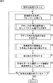
最初に符号化装置33の符号化部45により実行される符号化処理について図15のフローチャートを参照して説明する。
First, encoding processing executed by the
符号化処理が開始されると、符号化処理部45のブロック化部61は、最初にステップS1において、デジタル画像信号Vdg1を取得し、その取得したデジタル画像信号Vdg1に含まれる各フレーム画像データを所定の大きさのブロックに分割し、それをVQ部62に供給するとともに、処理をステップS2に進める。
When the encoding process is started, the blocking
次にステップS2において、VQ部62は、供給されたブロック単位の画像データを用いて、各ブロックの4隅の画素(特定画素)を抽出し、ベクトル量子化処理を実行することにより、各ブロックの4隅の画素(特定画素)で構成される各グループに対してベクトル量子化を施す。このベクトル量子化処理の詳細については後述する。VQ部62は、ベクトル量子化を行うと、得られたVQコードを選択コード情報Vcdvqとして出力部66(図3)に供給するとともに、そのVQコードに対応する代表値を予測部63(図3)に供給し、処理をステップS3に進める。
Next, in step S2, the
ステップS3において、予測部63は、ブロック内の、4隅の画素(特定画素)以外の各画素の画素値を予測し、その予測結果を残差算出部64に供給する。また、予測部63は、処理対象の画素がベクトルの4隅の画素(特定画素)である場合、VQ部62より供給された代表値を予測結果として残差算出部64に供給する。予測部63は、予測処理が終了すると、処理をステップS4に進める。
In step S <b> 3, the
ステップS4において、残差算出部64は残差算出処理を行い、予測部63より予測結果として供給される予測画素値と、デジタル画像信号Vdg1の画像データから残差を算出し、その残差を残差符号化部65に供給する。残差算出処理の詳細については後述する。残差算出処理を終了すると残差算出部64は、処理をステップS5に進める。
In step S4, the
ステップS5において、残差符号化部65は、残差符号化処理を実行し、残差算出部64より供給された残差を符号化し、符号化データVcddiffを生成する。残差符号化処理の詳細については後述する。残差符号化部65は、符号化データVcddiffを生成すると、それを出力部66に供給し、処理をステップS6に進める。
In step S5, the
ステップS6において、出力部66は、残差符号化部65より供給された符号化データVcddiffと、VQ部62より供給された選択コード情報Vcdvqを、符号化デジタル画像信号Vcd1として出力し、それを記録部46および復号部41に供給する。符号化デジタル画像信号Vcd1を出力すると、出力部66は、ステップS7において、符号化処理を終了するか否かを判定し、例えば全フレームについての処理が終了しておらず、符号化処理を終了しないと判定した場合、出力部66は、処理をステップS1に戻し、それ以降の処理を繰り返す。
In step S6, the
また、ステップS7において、全フレーム対する処理が終了したり、ユーザ指示等に基づいたりして符号化処理を終了すると判定した場合、出力部66は、符号化処理を終了する。
If it is determined in step S7 that the process for all frames is completed or the encoding process is ended based on a user instruction or the like, the
次に、図15のステップS2において実行されるベクトル量子化処理の詳細について図16のフローチャートを参照して説明する。 Next, details of the vector quantization processing executed in step S2 of FIG. 15 will be described with reference to the flowchart of FIG.
ベクトル量子化処理が開始されると、特定画素データ抽出部81は、ステップS21において、供給されたブロックの4隅の画素の画素値を抽出し、それをベクトル生成部82に供給する。ベクトル生成部82は、ステップS22において、抽出した特定画素をその位置によって所定の範囲毎にグループ化し、各グループについてベクトルを生成し、処理をステップS23に進める。
When the vector quantization process is started, the specific pixel
ステップS23において、画素パターン別コードブック83は、ベクトル生成部82によってベクトルが生成されたグループである処理対象グループの画素パターンに基づいて、使用するコードブックの種類を選択し、処理をステップS24に進める。ステップS24において、VQコード決定部84は、コードブックに基づいてベクトルに対応するVQコードを決定する。また、このとき、VQコード決定部84は、VQコードに対応する代表値を決定する。
In step S23, the
VQコード決定部84は、ベクトル量子化処理を終了するか否かを判定し、未処理のグループが存在し終了しないと判定した場合、処理をステップS23に戻し、それ以降の処理を繰り返す。また、ステップS25において、全フレームの全グループについて処理を終了し、ベクトル量子化処理を終了すると判定した場合、VQコード決定部84は、ベクトル量子化処理を終了し、図15のステップS2に処理を戻し、それ以降の処理を実行させる。
The VQ
次に、図15のステップS4において実行される残差算出処理の詳細について図17のフローチャートを参照して説明する。 Next, details of the residual calculation process executed in step S4 of FIG. 15 will be described with reference to the flowchart of FIG.
デジタル画像信号Vdg1の画像データおよび予測画素値を取得すると、画素判定部111は、ステップS41において、残差を算出する処理対象の画素(対象画素)の位置を確認する。ステップS42において、画素判定部111は、対象画素がブロックの4隅の画素(特定画素)であるか否かを判定する。
When the image data and the predicted pixel value of the digital image signal Vdg1 are acquired, the
ブロックの4隅の画素でないと判定した場合、画素判定部111は、処理をステップS43に進める。ステップS43において、差分値演算部112は、画像データにおける画素値と予測画素値の差分値を演算し、処理をステップS45に進める。
If it is determined that the pixel is not a pixel at the four corners of the block, the
また、ステップS42において、ブロックの4隅の画素であると判定した場合、画素判定部111は、処理をステップS44に進める。ステップS44において、差分値設定部113は、差分値を「0」に設定し(所定の値に設定し)、処理をステップS45に進める。
If it is determined in step S42 that the pixel is at the four corners of the block, the
ステップS45において残差出力部114は、ステップS43の処理またはステップS44の処理により得られた差分値を残差として出力し、残差符号化部65に供給する。ステップS46において、残差出力部114は、残差算出処理を終了するか否かを判定し、全フレームの全画素について残差を算出しておらず、残差算出処理を終了しないと判定した場合、処理をステップS41に戻し、それ以降の処理を繰り返す。また、ステップS46において、残差算出処理を終了すると判定した場合、残差算出処理を終了し、処理を図15のステップS4に戻し、それ以降の処理を実行させる。
In step S45, the
次に、図15のステップS5において実行される残差符号化処理の詳細について図18のフローチャートを参照して説明する。 Next, details of the residual encoding process executed in step S5 of FIG. 15 will be described with reference to the flowchart of FIG.
残差符号化処理が開始されると、DST変換部121は、ステップS61において、残差算出部64より供給された残差に対してDST変換処理を行い、ステップS62に処理を進める。ステップS62において、量子化部122は、DST変換された係数データに対して量子化処理を行い、処理をステップS63に進める。ステップS63において、ハフマン符号化部123は、量子化により得られた量子化係数データに対してハフマン符号化処理を行い、符号化データVcddiffを生成し、それを出力部66に供給する。
When the residual encoding process is started, the
ステップS64において、ハフマン符号化部123は、残差符号化処理を終了するか否かを判定し、符号化していない残差データが存在し、残差符号化処理を終了しないと判定した場合、ハフマン符号化部123は、処理をステップS61に戻し、それ以降の処理を繰り返す。また、ステップS64において、全ての残差データの符号化が終了し、残差符号化処理を終了すると判定した場合、ハフマン符号化部123は、残差符号化処理を終了し、図15のステップS5に処理を戻し、それ以降の処理を実行させる。
In step S64, the
以上のように符号化部45は、アナログ信号に生じるホワイトノイズや位相ずれ等のアナログ歪みを積極的に利用し、意図的に大きなアナログ歪みが画像信号に発生するように符号化処理を行うので、符号化処理や復号処理を繰り返す度に画像が大幅に劣化するようにすることができる。
As described above, the
例えば、図2の画像処理システム30において、アナログ画像信号Van1が、D/A42によるD/A変換時に信号の位相がずれることで生じる歪みを伴うとすると、A/D44によるA/D変換時のサンプリング位相の揺らぎのために、符号化部45でブロック化されて得られる各ブロックのブロック位置が、1回目の符号化、復号におけるブロック位置に対してずれたものとなる(ブロック位置が毎回異なる)。
For example, in the image processing system 30 of FIG. 2, assuming that the analog
そのため、符号化部45において、1回目にVQ部62で符号化する画素が毎回異なることとなる(特定画素が毎回変化する)。さらに、それらの特定画素は1回以上ハフマン符号化されたものであるため、VQ部62の符号化で用いたコードブック(画素パターン別コードブック83)の性質とは異なるものである。よって1回目に符号化する場合(符号化したことがない画素を符号化する場合)よりも量子化誤差の影響が大きくなる。
For this reason, in the
また、符号化部45は、予測部63において、VQ部62により符号化された特定画素の画素値(ベクトル量子化により得られた代表値)を用いて予測を行う。さらに、符号化部45は、残差算出部64において、その予測画素値とデジタル画像信号における画素値との残差を算出するが、位相がずれたことによりデジタル画像信号には1回目の符号化で特定画素になった画素と、そうでない画素とが混在しており、残差において高周波成分が発生する。そのため、残差符号化部65においてその残差を符号化すると、大きな歪みとなる。
In addition, the
以上のように、アナログ歪みを含むデジタル画像信号Vdg1が符号化部45において符号化された画像信号Vcd1を復号して得られるデジタル画像信号Vdg2(符号化装置33の復号部41が出力するデジタル画像信号Vdg2)は、再生装置31の復号部41から得られるデジタル画像信号Vdg0に比べて、大きく劣化したものとなる。
As described above, the digital image signal Vdg2 obtained by decoding the image signal Vcd1 obtained by decoding the digital image signal Vdg1 including analog distortion in the encoding unit 45 (the digital image output by the
つまり、例えば再生装置31が記録部46より読み出された符号化デジタル画像信号Vcd1を再生する場合、(再生装置31より出力されるアナログ画像信号Van1が2回目以降の符号化処理、および復号処理を経たものである場合)、上述したように符号化部45により符号化され、さらに復号部41により復号されて得られる画像データ(D/A42によりD/A変換されたアナログ画像信号Van2の画像データ)は、3回目以降の符号化処理および復号処理を経たものとなり、その画質はより一層劣化したものとなる。
That is, for example, when the
以上のように、記録部46により記録媒体に記録された符号化デジタル画像信号Vcd1を再生して得られる画像の画質は、再生装置31より出力されるアナログ画像信号Van1による画像に比べて大幅に劣化したものとなる。よって、この符号化装置33は、再生装置31より出力されるアナログ画像信号を、その画像の良好な画質を維持したまま複製することができない。
As described above, the image quality obtained by reproducing the encoded digital image signal Vcd1 recorded on the recording medium by the
なお、例えば、従来の方法で符号化処理および復号処理を繰り返し、それとともにA/D変換処理とD/A変換処理を繰り返すことにより、アナログ画像信号にはノイズ成分が生じるので、その画質は徐々に劣化するが、これは単にノイズ成分が蓄積されていくのみであり、本発明を適用した画像処理システム30による符号化処理および復号処理とは異なる。 Note that, for example, a noise component is generated in an analog image signal by repeating the encoding process and the decoding process with a conventional method, and simultaneously repeating the A / D conversion process and the D / A conversion process, so that the image quality gradually increases. However, this is merely the accumulation of noise components, which is different from the encoding processing and decoding processing by the image processing system 30 to which the present invention is applied.
つまり単にノイズ成分が蓄積される場合の画質の劣化は、S/N比が十分低ければ、通常、画像が破綻することはない(絵の内容を理解できなくなることはない)。また、そのノイズ成分の除去(画質を向上させること)も容易である。これに対して本発明の符号化処理においては、上述したように、アナログ歪みを利用して、大きな歪みを生成し、画像を破綻させる(画質を大幅に劣化させる)ので、従来の方法の「単にノイズ量が増えS/N比が高くなる」とは異なる効果を得ることができる。 In other words, image quality degradation when the noise component is simply accumulated usually does not cause the image to break down if the S / N ratio is sufficiently low (the picture content cannot be understood). Further, it is easy to remove the noise component (improve image quality). On the other hand, in the encoding process of the present invention, as described above, analog distortion is used to generate a large distortion and corrupt the image (the image quality is greatly degraded). It is possible to obtain an effect different from “simply increasing the amount of noise and increasing the S / N ratio”.
また、このように符号化処理において画質を大幅に劣化させるので、例えば、表示装置32がディスプレイ43に画像を表示させるときのように、複製前の画像信号の画像は破綻せずに正常に表示される。
In addition, since the image quality is greatly deteriorated in the encoding process in this way, the image of the image signal before duplication is displayed normally without failure as in the case where the
つまり、符号化部45は、スクランブル処理や雑音情報を埋め込む等の特別な処理を必要とせずに、アナログ信号の良好な品質の複製のみを防止することができる。これにより、符号化装置33は、画像が表示されなくなる、回路規模の増大を招く等の不都合を発生させずに、アナログ信号を利用した不正コピーを抑制することができる。
That is, the
なお、仮に、アナログ歪みがない場合(例えば、復号部41が出力するデジタル画像信号Vdg0を直接符号化する場合)、信号に位相ずれが生じないため、1回目の符号化処理においてVQ部62により符号化された画素(特定画素)は、2回目の符号化処理においても符号化される(1回目の符号化処理において特定画素とされた画素は、2回目の符号化処理においても特定画素とされる)。また、この画素の符号化された画素値(コード)は復号処理においても利用されるため、何回目のベクトル量子化であっても、1回目と全く同じ結果が得られる。従って、それ以降の処理の結果も1回目とほぼ同じになり、符号化部45は、何回目の符号化処理であっても、略同一な符号化データを得ることができる。換言すると、復号部41は、何回目の復号処理であっても、略同一な符号化データを復号することになり、通常の品質での再生が可能となる。
If there is no analog distortion (for example, when the digital image signal Vdg0 output from the
次に、図19のフローチャートを参照して、復号部41(図2)による復号処理の流れの例を説明する。 Next, an example of the flow of decoding processing by the decoding unit 41 (FIG. 2) will be described with reference to the flowchart of FIG.
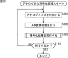
復号処理が開始されると、最初に、データ分解部151(図12)は、ステップS81において、符号化デジタル画像信号Vcdを取得し、その信号に含まれる符号化データと選択コード情報を抽出し、それぞれに分離する。 When the decoding process is started, first, in step S81, the data decomposing unit 151 (FIG. 12) acquires the encoded digital image signal Vcd, and extracts the encoded data and selection code information included in the signal. , Separate into each.
ステップS82において、逆VQ部152は、その分離された選択コード情報を用いて逆ベクトル量子化処理を行い、ブロックの4隅の画素値(特定画素の画素値)を算出する(つまり、選択コード情報Vcdvqのコードに対応する代表値を決定する)。ステップS83において、予測部153は、そのブロックの4隅の画素値(代表値)を用いて、そのブロック内の各画素の値を予測する。
In step S82, the
ステップS84において、残差復号部154は、データ分解部151により分離された符号化データに対して残差復号処理を行い、それを復号する。残差復号処理の詳細については後述する。残差復号処理が終了すると残差復号部154は、処理をステップS85に進める。
In step S84, the
ステップS85において、画素値加算部155は、ステップS83の処理により得られた予測画素値と、ステップS84の残差復号処理により得られた残差の加算演算処理を行う。加算演算処理の詳細については後述する。加算演算処理が終了すると画素値加算部155は、処理をステップS86に進める。
In step S85, the pixel
ステップS86において、ブロック分解部156は、ステップS85の加算演算処理により得られた加算結果をデジタル画像信号Vdgとして出力する。ステップS87においてブロック分解部156は、復号処理を終了するか否かを判定し、例えば、まだ復号していない画像データが存在し、復号処理を終了しないと判定した場合、ブロック分解部156は、処理をステップS81に戻し、それ以降の処理を繰り返す。また、例えば、ステップS87において、全ての画像データを復号し、復号処理を終了すると判定した場合、ブロック分解部156は、復号処理を終了する。
In step S86, the
次に、図20のフローチャートを参照して、図19のステップS84において実行される残差復号処理の詳細について説明する。 Next, details of the residual decoding process executed in step S84 of FIG. 19 will be described with reference to the flowchart of FIG.
残差復号処理が開始されると、最初に、ステップS101において、残差復号部154のハフマン復号部161は、符号化データVcddiffに対してハフマン復号処理を行い、量子化係数データを得る。ステップS102において、逆量子化部162は、ステップS101の処理により得られた量子化係数データに対して逆量子化処理を行い、DSTの係数データを得る。ステップS103において、IDST変換部163は、ステップS102の処理により得られた係数データに対してIDST変換処理を行い、復号された残差を得る。ステップS104においてIDST変換部163は、残差復号処理を終了するか否かを判定し、まだ全ての符号化データVcddiffに対して残差復号処理を行っておらず、残差復号処理を終了しないと判定した場合、処理をステップS101に戻し、それ以降の処理を繰り返す。
When the residual decoding process is started, first, in step S101, the
また、ステップS104において、全ての符号化データVcddiffに対する処理が完了し、残差復号処理を終了すると判定した場合、IDST変換部163は、残差復号処理を終了し、処理を図19のステップS84に戻し、それ以降の処理を実行させる。
If it is determined in step S104 that the processing for all the encoded data Vcddiff is completed and the residual decoding process is to be ended, the
次に、図19のステップS85において実行される加算演算処理の詳細について図21のフローチャートを参照して説明する。 Next, details of the addition calculation processing executed in step S85 in FIG. 19 will be described with reference to the flowchart in FIG.
画素値加算部155の画素判定部177は、ステップS121において、予測画素値および残差を取得し、加算処理を行う対象画素の位置を確認する。そして、画素判定部177は、ステップS122において、処理の対象画素がブロックの4隅の画素(特定画素)であるか否かを判定し、ブロックの4隅の画素(特定画素)であると判定した場合、処理をステップS123に進める。
In step S121, the pixel determination unit 177 of the pixel
ステップS123において、残差設定部172は、残差を「0」に設定し、処理をステップS124に進める。また、ステップS122において、処理の対象画素がブロックの4隅の画素(特定画素)でないと判定した場合、画素判定部171は、処理をステップS124に進める。
In step S123, the
ステップS124において、加算値演算部173は、取得した予測画素値と残差を加算する。順序整列部174は、その加算結果を保持し、ステップS125において加算演算処理を終了するか否かを判定し、未処理の予測画素値または残差が存在し、加算演算処理を終了しないと判定した場合、処理をステップS121に戻し、それ以降の処理を繰り返させる。また、ステップS125において、加算演算処理を終了すると判定した場合、順序整列部174は、ステップS126に処理を進め、加算結果を並び替え、加算演算処理を終了し、処理を図19のステップS85に戻し、それ以降の処理を実行させる。
In step S124, the
以上のように、復号部41は、符号化部45の符号化処理に対応する復号方法で符号化データを復号する。このようにすることにより、復号部41は、符号化部45により、アナログ信号に生じるホワイトノイズや位相ずれ等のアナログ歪みを積極的に利用して意図的に付加された大きなアナログ歪みが画像信号に残るように復号処理を行うので、符号化処理や復号処理を繰り返す度に画像が大幅に劣化するようにすることができる。
As described above, the
つまり、復号部41は、スクランブル処理や雑音情報を埋め込む等の特別な処理を必要とせずに、アナログ信号の良好な品質の複製のみを防止することができる。これにより、再生装置31は、画像が表示されなくなる、または回路規模の増大を招く等の不都合を発生させずに、アナログ信号を利用した不正コピーを抑制し、安全にアナログ信号を出力することができる。
That is, the
つまり、画像処理システム30においては、符号化装置33が、再生装置31より出力されるアナログ画像信号を、その画像の画質を劣化させないように複製することができないようになされている。従って、画像処理システム30は、回路規模の増大やコストの上昇等の不都合を発生させずに、アナログ信号を利用した不正コピーを抑制し、安全にアナログ信号を出力することができる。また、例えば、編集作業における複製等のように、デジタル信号を用いて複製を行う場合、画像処理システム30は、画質を劣化させずに複製を行うことができる。なお、その場合、画像処理システム30からD/A42およびA/D44が省略される。また、その場合の著作権管理は、例えばDRM(Digital Rights Management)等の他の技術を併用することにより行うことができるので、画像処理システム30は、デジタル信号の不正な複製も抑制することができる。
That is, in the image processing system 30, the
なお、以上においては、残差の符号化方法として、DST変換処理を行うように説明したが、これに限らず、例えば、残差の波形を関数で近似し、その係数を伝送する関数近似符号化を用いるようにしてもよい。 In the above description, the DST conversion process has been described as the residual encoding method. However, the present invention is not limited to this. For example, the function approximation code that approximates the residual waveform with a function and transmits the coefficient is used. It is also possible to use a conversion.
図22は、その場合の残差符号化部65(図3)の詳細な構成例を示すブロック図であり、図9に対応する図である。 FIG. 22 is a block diagram showing a detailed configuration example of the residual encoding unit 65 (FIG. 3) in that case, and corresponds to FIG.
図22において残差符号化部65は、DST変換部121(図9)の代わりに、関数近似変換部191を有している。また、図22の残差符号化部65は、図9の場合と同様に、量子化部122およびハフマン符号化部123も有している。
In FIG. 22, the
関数近似変換部191は、ブロック毎の残差に対して、図23に示されるように各画素位置を座標で表し、各画素値により構成される波形を、例えば、3次元関数を近似させることにより表す。
As shown in FIG. 23, the function
例えば、図23の場合、関数近似変換部191は、ブロックの左下の画素を基準点とし、水平方向をx軸、垂直方向をy軸とし、各画素の位置を座標化する(図23の場合、0≦x≦7,0≦y≦7)。次に、関数近似変換部191は、各画素の画素値で構成される波形を、近似関数を用いて関数化する。例えば、関数近似変換部191は、以下の式(5)に示されるような3次元関数を、最小2乗法を用いる等して、画素値の波形に近似させる。
For example, in the case of FIG. 23, the function
![]()
![]()
なお、残差算出部64によりブロックの4隅の残差の値は「0」に設定されているので、式(5)において、以下の式(6)の条件が付加される。
Since the residual values at the four corners of the block are set to “0” by the
Z(0,0)=Z(0,7)=Z(7,0)=Z(7,7)=0 ・・・(6) Z (0,0) = Z (0,7) = Z (7,0) = Z (7,7) = 0 (6)
関数近似変換部191は、最小2乗法を行う等して、式(5)の関数を画素値の波形に近似させたときの係数a乃至iを算出し、その係数a乃至iを係数データとして量子化部122に供給する。
The function
量子化部122は、その供給された係数データを図9の場合と同様に量子化する。また、ハフマン符号化部123も、図9の場合と同様に、量子化部122において得られた量子化係数データを符号化し、符号化データを生成する。
The
なお、この場合、復号部41(図2)の残差復号部154(図12)は、この関数近似変換処理に対応する方法で復号処理を行う。 In this case, the residual decoding unit 154 (FIG. 12) of the decoding unit 41 (FIG. 2) performs the decoding process by a method corresponding to the function approximate conversion process.
図24は、その場合の残差復号部154の詳細な構成例を示すブロック図であり、図13に対応する図である。
FIG. 24 is a block diagram illustrating a detailed configuration example of the
図24において、残差復号部154は、図13の場合と同様に、ハフマン復号部161および逆量子化部162を有し、図13のIDST変換部163の代わりに逆関数近似変換部192を有している。
24, the
逆関数近似変換部192は、逆量子化部162による逆量子化処理により得られた係数データを用いて(係数データを式(5)に代入して)近似関数を生成し、その近似関数から各画素との画素値を算出する。つまり、逆関数近似変換部192は、近似関数(式(5))の変数X,Yにそれぞれx座標、y座標を代入して各画素値(残差)を算出する。
The inverse function
以上のような関数近似変換を利用した残差符号化処理の流れを図25のフローチャートを参照して説明する。このフローチャートは、図18のフローチャートに対応する。 The flow of the residual encoding process using the function approximation transformation as described above will be described with reference to the flowchart of FIG. This flowchart corresponds to the flowchart of FIG.
すなわち、残差符号化処理が開始されると、関数近似変換部191は、ステップS141において、供給された残差に対して関数近似変換処理を行い、ブロック毎に、各画素の残差により構成される波形を関数化し、近似関数の係数データを生成する。ステップS142において、量子化部122は、その係数データに対して、図18のステップS62の場合と同様に量子化処理を行い、量子化係数データを生成する。ステップS143においてハフマン符号化部123は、その量子化係数データに対して、図18のステップS63の場合と同様にハフマン符号化処理を行い、符号化データVcddiffを生成する。
That is, when the residual encoding process is started, the function
ステップS144において、ハフマン符号化部123は、残差符号化処理を終了するか否かを判定し、未処理の残差が存在し、残差符号化処理を終了しないと判定した場合、処理をステップ141に戻し、それ以降の処理を繰り返す。また、ステップS144において、残差符号化処理を終了すると判定した場合、ハフマン符号化部123は、残差符号化処理を終了し、処理を図15のステップS5に戻し、それ以降の処理を実行させる。
In step S144, the
このように関数近似変換処理を行うことにより、符号化部45は、DST変換処理を行う場合と同様に、アナログ信号を利用して複製を行う場合のみ情報の品質が劣化するようにすることができる。従って、符号化装置33は、この場合も、回路規模の増大を招く等の不都合を発生させずに、2回目以降の符号化処理および復号処理では画像データを著しく劣化させ、アナログ信号を利用した不正コピーを抑制することができる。
By performing the function approximation conversion process in this way, the
次に、図26のフローチャートを参照して、図25のフローチャートを参照して説明した符号化処理に対応する復号処理、すなわち、関数近似変換処理を利用した復号処理の流れについて説明する。この図26のフローチャートは、図20のフローチャートに対応する。 Next, with reference to the flowchart of FIG. 26, the decoding process corresponding to the encoding process described with reference to the flowchart of FIG. 25, that is, the flow of the decoding process using the function approximate conversion process will be described. The flowchart of FIG. 26 corresponds to the flowchart of FIG.
残差復号処理が開始されると、ステップS161において、ハフマン復号部161は、図20のステップS101と同様に、符号化データVcddiffに対してハフマン復号処理を行い、量子化係数データを生成する。ステップS162において、逆量子化部162は、図20のステップS102と同様に、量子化係数データに対して逆量子化処理を行い、係数データを生成する。逆関数近似変換部192は、ステップS163において、逆関数変換処理を行い、係数データから元の画素値(残差)を算出する。
When the residual decoding process is started, in step S161, the
ステップS164において、逆関数近似変換部192は、残差復号処理を終了するか否かを判定し、例えば未処理の符号化データが存在し、残差復号処理を終了しないと判定した場合、処理をステップS161に戻し、それ以降の処理を繰り返させる。また、ステップS164において、残差復号処理を終了すると判定した場合、逆関数近似変換部192は、残差復号処理を終了し、処理を図19のステップS84に処理を戻し、それ以降の処理を実行させる。
In step S164, the inverse function
このように符号化部45の関数近似変換処理に対応して逆関数近似変換処理を行うので、復号部41は、IDST変換処理を行う場合と同様に、アナログ信号を利用して複製を行う場合のみ情報の品質が劣化するようにすることができる。従って、再生装置31は、この場合も、回路規模の増大を招く等の不都合を発生させずに、2回目以降の符号化処理および復号処理では画像データを著しく劣化させ、アナログ信号を利用した不正コピーを抑制することができる。
As described above, the inverse function approximate conversion process is performed in response to the function approximate conversion process of the
すなわち、符号化部45において関数近似変換処理を行い、復号部41において逆関数近似変換処理を行う場合も、画像処理システム30は、回路規模の増大やコストの上昇等の不都合を発生させずに、アナログ信号を利用した不正コピーを抑制し、安全にアナログ信号を出力することができる。また、例えば、編集作業における複製等のように、デジタル信号を用いて複製を行う場合、画像処理システム30は、画質を劣化させずに複製を行うことができる。また、例えばDRM等の他の技術を併用することにより、画像処理システム30は、デジタル信号の不正な複製も抑制することができる。
That is, even when the function approximation conversion process is performed in the
なお、画像処理システム30の各装置の構成は、図2に示される以外であってもよく、例えば、図27に示されるように、符号化装置33の復号部41、D/A42、およびディスプレイ43は省略するようにしてもよい。
The configuration of each device of the image processing system 30 may be other than that shown in FIG. 2, for example, as shown in FIG. 27, the
図27は、本発明を適用した画像処理システムの他の構成例を示す図であり、図2に対応する図である。つまり、図27の画像処理システム210は、図2の画像処理システム30に対応しており、画像処理システム30の符号化装置33の代わりに符号化装置213を有している。
FIG. 27 is a diagram showing another configuration example of the image processing system to which the present invention is applied, and corresponds to FIG. That is, the image processing system 210 in FIG. 27 corresponds to the image processing system 30 in FIG. 2, and includes an
符号化装置213は、図2の符号化装置33に対応する装置であり、符号化装置33の構成から、復号部41、D/A42、およびディスプレイ43を省略した構成となっている。
The
つまり、画像処理システム210の符号化装置213は、図2の符号化装置33と同様に、再生装置31が出力したアナログ画像信号Van1を取得し、それをデジタル化して符号化した符号化デジタル画像信号Vcd1を生成し、それを記録媒体に記録するのみであり、符号化装置33のように、符号化デジタル画像信号を再度復号し、アナログ画像信号Van2を生成してディスプレイに画像を表示することはしない。
That is, the
図2の符号化装置33は、符号化した画像信号を再度復号する場合を説明するために便宜上適用した構成であり、実際には、符号化を行うことができればよく、そのような構成が必要なわけではない。
The
また、図2(図27)において、1つの装置として説明した各装置の構成を複数の装置として構成するようにしてもよいし、逆に、複数の装置を1つの装置として構成するようにしてもよい。 In FIG. 2 (FIG. 27), the configuration of each device described as one device may be configured as a plurality of devices, or conversely, a plurality of devices may be configured as one device. Also good.
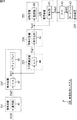
図28は、本発明を適用した画像処理システムのさらに他の構成例を示す図である。図28の画像処理システム220は、図2の画像処理システム30に対応する。図28において、画像処理システム220は、2つの復号装置221、2つの表示装置222、A/D変換装置223、符号化装置224、および記録装置225により構成されている。
FIG. 28 is a diagram showing still another configuration example of the image processing system to which the present invention is applied. An image processing system 220 in FIG. 28 corresponds to the image processing system 30 in FIG. In FIG. 28, the image processing system 220 includes two
復号装置221は復号部41を有し、表示装置222はD/A42およびディスプレイ43を有し、A/D変換装置223はA/D44を有し、符号化装置224は符号化部45を有し、記録装置225は記録部46を有している。
The
つまり、画像処理システム220は、装置の構成が異なるだけで、処理部の構成は図2の画像処理システム30と同じである。従って、画像処理システム220は、各装置により画像処理システム30と同様の処理が行われるので、画像処理システム30と同様に、アナログ信号を利用したコンテンツデータの不正な複製を抑制することができる。 That is, the image processing system 220 is the same as the image processing system 30 in FIG. 2 except that the configuration of the apparatus is different. Therefore, in the image processing system 220, the same processing as that of the image processing system 30 is performed by each device. Therefore, similarly to the image processing system 30, unauthorized duplication of content data using an analog signal can be suppressed.
また、図2の画像処理システムに上述した構成以外の構成を追加するようにしてもよい。例えば、アナログ画像信号の複製ではより大幅に画質が劣化するように、アナログ画像信号Vanに積極的にノイズ成分(ホワイトノイズや位相ずれ等のアナログ歪み)を付加するようにしてもよい。ただし、このノイズ成分は、単にS/N比を向上させるために付加されるものではなく、上述した符号化処理や復号処理において画質をより劣化させるために(画像信号により大きな歪みを生じさせるために)積極的に利用するために付加されるものである。 Moreover, you may make it add the structure other than the structure mentioned above to the image processing system of FIG. For example, a noise component (analog distortion such as white noise or phase shift) may be positively added to the analog image signal Van so that the image quality is significantly deteriorated when the analog image signal is copied. However, this noise component is not simply added to improve the S / N ratio, but to further deteriorate the image quality in the encoding process or decoding process described above (to cause a large distortion in the image signal). It is added for active use.
図29は、本発明を適用した画像処理システムのさらに他の構成例を示す図であり、図2および図28に対応する図である。 FIG. 29 is a diagram showing still another configuration example of the image processing system to which the present invention is applied, and corresponds to FIG. 2 and FIG.
図29において、画像処理システム240は、2つの再生装置241、符号化装置242、2つの表示装置32、および記録装置225により構成されている。表示装置32は、図2を参照して説明したように、再生装置241が出力するアナログ画像信号Van1またはVan2の画像をディスプレイ43に表示する装置である。記録装置225は、図28を参照して説明したように、記録部46を有しており、符号化装置242が出力する符号化デジタル画像信号Vcd1を記録部46の記録媒体に記録する。
In FIG. 29, the image processing system 240 includes two
再生装置241は、再生装置31と同様に復号部41およびD/A42を有しており、さらに、アナログノイズ付加部251を有している。アナログノイズ付加部251は、D/A42において変換されたアナログ画像信号にノイズ成分(アナログノイズ)を付加する。
The
ここで、アナログノイズは、アナログ信号に付加されるノイズ成分のことであり、アナログ成分に対するノイズ成分のことである。換言すると、アナログノイズは、例えば、ホワイトノイズや位相ずれ等のようにアナログ歪み(アナログ成分の歪み)を発生させるノイズ成分のことである。 Here, the analog noise is a noise component added to the analog signal, and is a noise component with respect to the analog component. In other words, the analog noise is a noise component that generates analog distortion (analog component distortion) such as white noise and phase shift.
つまり、再生装置241は、積極的にアナログノイズを付加したアナログ画像信号Vanを出力する。例えば、再生装置241は、符号化デジタル画像信号Vcd0より、積極的にアナログノイズを付加したアナログ画像信号Van1を生成する。また、例えば、再生装置241は、符号化デジタル画像信号Vcd1より、積極的にアナログノイズを付加したアナログ画像信号Van2を生成する。
That is, the
符号化装置242は、図2の符号化装置33と同様にA/D44および符号化部45を有しており、さらに、アナログノイズ付加部251も有している。つまり、符号化装置242は、アナログノイズ付加部251において積極的にアナログノイズが付加されたアナログ画像信号をA/D44においてA/D変換し、符号化部45において符号化する。
The
図29の画像処理システム240において、符号化装置242が実行する、アナログ画像信号に積極的にアナログノイズを付加して符号化するアナログ劣化符号化処理について、図30のフローチャートを参照して説明する。
In the image processing system 240 of FIG. 29, an analog deterioration encoding process performed by the
最初に、ステップS181において、アナログノイズ付加部251は、再生装置241より出力されたアナログ画像信号Vanにアナログノイズ(ホワイトノイズや位相ずれ等)を付加する。ステップS182において、符号化装置242は、アナログノイズ付加部251より出力された、積極的にアナログノイズが付加されたアナログ画像信号Vanに対してA/D変換処理を行い、デジタル画像信号Vdgを生成する。そして、ステップS183において、符号化部45は、符号化処理を行う。この符号化処理は、図15のフローチャートを参照して説明した符号化処理と同様の処理を行うので、その詳細についての説明を省略する。
First, in step S181, the analog
符号化処理が終了すると、符号化部45は、ステップS184に処理を進め、アナログ劣化符号化処理を終了するか否かを判定し、終了しないと判定した場合、ステップS181に処理を戻し、それ以降の処理を繰り返す。また、ステップS184においてアナログ劣化符号化処理を終了すると判定した場合、アナログ劣化符号化処理を終了する。
When the encoding process ends, the
次に、図29の画像処理システム240において、再生装置241が実行する、復号したアナログ画像信号に積極的にアナログノイズを付加するアナログ劣化復号処理について、図31のフローチャートを参照して説明する。
Next, an analog deterioration decoding process for positively adding analog noise to the decoded analog image signal, which is executed by the
最初に、ステップS201において、復号部41は、入力された符号化デジタル画像信号に対して復号処理を行う。この復号処理は、図19のフローチャートを参照して説明した復号処理と同様の処理を行うので、その詳細についての説明を省略する。
First, in step S201, the
復号処理が終了し、デジタル画像信号Vdgが得られると、D/A42は、ステップS202において、そのデジタル画像信号Vdgに対してD/A変換処理を行い、アナログ画像信号Vanを得る。ステップS203において、アナログノイズ付加部251は、D/A42においてD/A変換されたアナログ画像信号Vanにアナログノイズ(ホワイトノイズや位相ずれ等)を付加する。
When the decoding process is completed and the digital image signal Vdg is obtained, the D /
アナログノイズを付加すると、アナログノイズ付加部251は、ステップS204に処理を進め、アナログ劣化復号処理を終了するか否かを判定し、終了しないと判定した場合、ステップS201に処理を戻し、それ以降の処理を繰り返す。また、ステップS204においてアナログ劣化復号処理を終了すると判定した場合、アナログ劣化復号処理を終了する。
When the analog noise is added, the analog
このように、符号化装置242は積極的にアナログ画像信号にアナログノイズを付加する。従って、画像処理システム240においてアナログ信号を利用して複製を行う場合、符号化処理および復号処理が繰り返されることにより、アナログ画像信号にノイズが積極的に付加されていき、その画像の画質はより顕著に劣化するので、符号化装置242は、アナログ信号を利用したコンテンツデータの不正な複製をより抑制するように符号化処理を行うことができる。
Thus, the
同様に、再生装置241も積極的にアナログ画像信号にアナログノイズを付加する。従って、再生装置241は、アナログ信号を利用したコンテンツデータの不正な複製をより抑制するように復号処理を行うことができる。
Similarly, the
すなわち、画像処理システム240は、画像が表示されなくなる、回路規模の増大を招く等の不都合を発生させずに、2回目以降の符号化処理および復号処理では画像データをより著しく劣化させ、アナログ信号を利用した不正コピーをより抑制することができる。 That is, the image processing system 240 does not cause inconveniences such as an image not being displayed or an increase in the circuit scale, and the image data is deteriorated significantly in the second and subsequent encoding processes. It is possible to further suppress unauthorized copying using.
上述した一連の処理は、ハードウェアにより実行させることもできるし、ソフトウエアにより実行させることもできる。この場合、例えば、図2の画像処理システム30、図27の画像処理システム210、図28の画像処理システム220、および図29の画像処理システム240を構成する各装置は、それぞれ、図32に示されるようなパーソナルコンピュータとして構成されるようにしてもよい。 The series of processes described above can be executed by hardware or can be executed by software. In this case, for example, the devices constituting the image processing system 30 in FIG. 2, the image processing system 210 in FIG. 27, the image processing system 220 in FIG. 28, and the image processing system 240 in FIG. 29 are shown in FIG. It may be configured as such a personal computer.
図32において、パーソナルコンピュータ300のCPU(Central Processing Unit)301は、ROM(Read Only Memory)302に記憶されているプログラム、または記憶部313からRAM(Random Access Memory)303にロードされたプログラムに従って各種の処理を実行する。RAM303にはまた、CPU301が各種の処理を実行する上において必要なデータなども適宜記憶される。
In FIG. 32, a CPU (Central Processing Unit) 301 of the personal computer 300 performs various processes according to a program stored in a ROM (Read Only Memory) 302 or a program loaded from a
CPU301、ROM302、およびRAM303は、バス304を介して相互に接続されている。このバス304にはまた、入出力インタフェース310も接続されている。
The
入出力インタフェース310には、キーボード、マウスなどよりなる入力部311、CRT(Cathode Ray Tube)、LCD(Liquid Crystal Display)などよりなるディスプレイ、並びにスピーカなどよりなる出力部312、ハードディスクなどより構成される記憶部313、モデムなどより構成される通信部314が接続されている。通信部314は、インターネットを含むネットワークを介しての通信処理を行う。
The input /
入出力インタフェース310にはまた、必要に応じてドライブ315が接続され、磁気ディスク、光ディスク、光磁気ディスク、或いは半導体メモリなどのリムーバブルメディア321が適宜装着され、それらから読み出されたコンピュータプログラムが、必要に応じて記憶部313にインストールされる。
A drive 315 is connected to the input /
上述した一連の処理をソフトウエアにより実行させる場合には、そのソフトウエアを構成するプログラムが、ネットワークや記録媒体からインストールされる。 When the above-described series of processing is executed by software, a program constituting the software is installed from a network or a recording medium.
この記録媒体は、例えば、図32に示されるように、装置本体とは別に、ユーザにプログラムを配信するために配布される、プログラムが記録されている磁気ディスク(フレキシブルディスクを含む)、光ディスク(CD-ROM(Compact Disk-Read Only Memory),DVD(Digital Versatile Disk)を含む)、光磁気ディスク(MD(Mini-Disk)(登録商標)を含む)、もしくは半導体メモリなどよりなるリムーバブルメディア321により構成されるだけでなく、装置本体に予め組み込まれた状態でユーザに配信される、プログラムが記録されているROM302や、記憶部313に含まれるハードディスクなどで構成される。
For example, as shown in FIG. 32, the recording medium is distributed to distribute the program to the user separately from the apparatus main body, and includes a magnetic disk (including a flexible disk) on which the program is recorded, an optical disk ( Removable media 321 composed of CD-ROM (compact disk-read only memory), DVD (digital versatile disk), magneto-optical disk (including MD (mini-disk) (registered trademark)), or semiconductor memory In addition to being configured, it is configured by a
なお、本明細書において、記録媒体に記録されるプログラムを記述するステップは、記載された順序に沿って時系列的に行われる処理はもちろん、必ずしも時系列的に処理されなくとも、並列的あるいは個別に実行される処理をも含むものである。 In the present specification, the step of describing the program recorded on the recording medium is not limited to the processing performed in chronological order according to the described order, but is not necessarily performed in chronological order. It also includes processes that are executed individually.
また、本明細書において、システムとは、複数のデバイス(装置)により構成される装置全体を表すものである。 Further, in this specification, the system represents the entire apparatus composed of a plurality of devices (apparatuses).
30 画像処理システム, 31 再生装置, 33 符号化装置, 41 復号部, 42 D/A, 44 A/D, 45 符号化部, 61 ブロック化部, 62 VQ部, 63 予測部, 64 残差算出部, 65 残差符号化部, 66 出力部, 81 特定画素データ抽出部, 82 ベクトル生成部, 83 画素パターン別コードブック, 84 VQコード決定部, 111 画素判定部, 112 差分値演算部, 113 差分値設定部, 114 残差出力部, 121 DST変換部, 122 量子化部, 123 ハフマン符号化部, 151 データ分解部, 152 逆VQ部, 153 予測部, 154 残差復号部, 155 画素値加算部, 156 ブロック分解部, 161 ハフマン復号部, 162 逆量子化部, 163 IDST変換部, 171 画素判定部, 172 残差設定部, 173 加算値演算部, 174 順序整列部, 191 関数近似変換部, 192 逆関数近似変換部, 210 画像処理システム, 213 符号化装置, 220 画像処理システム, 221 復号装置, 224 符号化装置, 240 画像処理システム, 241 再生装置, 242 符号化装置, 251 アナログノイズ付加部, 300 パーソナルコンピュータ 30 image processing system, 31 playback device, 33 encoding device, 41 decoding unit, 42 D / A, 44 A / D, 45 encoding unit, 61 blocking unit, 62 VQ unit, 63 prediction unit, 64 residual calculation , 65 residual encoding unit, 66 output unit, 81 specific pixel data extraction unit, 82 vector generation unit, 83 pixel pattern-specific code book, 84 VQ code determination unit, 111 pixel determination unit, 112 difference value calculation unit, 113 Difference value setting unit, 114 residual output unit, 121 DST conversion unit, 122 quantization unit, 123 Huffman coding unit, 151 data decomposition unit, 152 inverse VQ unit, 153 prediction unit, 154 residual decoding unit, 155 pixel value Adder, 156 Block decomposing unit, 161 Huffman decoding unit, 162 Inverse quantization unit, 163 IDST conversion unit, 171 Pixel determination unit, 172 residual setting unit, 173 addition value calculation unit, 174 order alignment unit, 191 function approximation conversion unit, 192 inverse function approximation conversion unit, 210 image processing system, 213 encoding device, 220 image processing system, 221 Decoding device, 224 encoding device, 240 image processing system, 241 playback device, 242 encoding device, 251 analog noise adding unit, 300 personal computer
Claims (24)
前記入力画像データの各フレーム画像を複数のブロックに分割してブロック化するブロック化手段と、
前記ブロック化手段によりブロック化されて得られた各ブロックの周縁部の複数の画素を特定画素とし、前記特定画素に限らない全画素群の中で互いに隣接する特定画素群をグループとし、前記グループ毎に前記特定画素の画素値をベクトル量子化するベクトル量子化手段と、
各ブロックにおいて、前記ベクトル量子化手段によりベクトル量子化された前記特定画素の画素値に基づいて、前記ブロック内の前記特定画素以外の各画素の画素値を予測する予測手段と、
前記ブロック内の前記特定画素以外の各画素について、前記予測手段により予測された画素値である予測画素値と前記入力画像データ中の画素値との差分を算出する差分算出手段と、
前記差分算出手段により得られた前記差分を前記ブロック毎に符号化する差分符号化手段と
を備える符号化装置。 An encoding device that encodes input image data including analog distortion ,
Blocking means for dividing each frame image of the input image data into a plurality of blocks ,
Wherein the blocking means and the specific pixel a plurality of pixels of the peripheral portion of each block obtained by the block of, and a group specific pixel group adjacent to each other among all the pixel group not limited to the specific pixel, Vector quantization means for vector-quantizing the pixel value of the specific pixel for each group ;
Prediction means for predicting the pixel value of each pixel other than the specific pixel in the block on the basis of the pixel value of the specific pixel vector-quantized by the vector quantization means in each block ;
For each pixel other than the specific pixel in the block, a difference calculation unit that calculates a difference between a predicted pixel value that is a pixel value predicted by the prediction unit and a pixel value in the input image data;
Encoding apparatus Ru and a differential encoding means for encoding each said block the difference obtained by the difference calculation means.
請求項1に記載の符号化装置。 The vector quantization means sets the four corner pixels of each block as specific pixels .
Encoding apparatus according to 請 Motomeko 1.
請求項1に記載の符号化装置。The encoding device according to claim 1.
請求項1に記載の符号化装置。 The prediction means sets a pixel value of each pixel other than the specific pixel in the block to a pixel value of the specific pixel closest to the pixel.
Encoding apparatus according to 請 Motomeko 1.
前記差分符号化手段は、前記特定画素を含む前記ブロック内の全ての画素の前記差分を符号化する
請求項1に記載の符号化装置。 The difference calculation means further sets the difference of the specific pixel to “0”,
The difference encoding means encodes the difference of all pixels in the block including the specific pixel.
Encoding apparatus according to 請 Motomeko 1.
前記差分算出手段により得られた前記差分を直交変換する直交変換手段と、
前記直交変換手段により前記差分が直交変換されて得られた係数データを量子化する量子化手段と、
前記量子化手段により前記係数データが量子化されて得られた量子化係数データを可変長符号化する可変長符号化手段と
を備える請求項1に記載の符号化装置。 The differential encoding means includes
Orthogonal transformation means for orthogonally transforming the difference obtained by the difference calculation means;
Quantization means for quantizing coefficient data obtained by orthogonally transforming the difference by the orthogonal transform means;
Encoding apparatus according to 請 Motomeko 1 and a variable-length coding means for variable length coding the quantized coefficient data to which the coefficient data is obtained are quantized by the quantization means.
請求項6に記載の符号化装置。 The orthogonal transform means performs discrete sine transform on the difference.
Encoding apparatus according to 請 Motomeko 6.
請求項1に記載の符号化装置。 Selection code information that is information related to a code corresponding to a vector quantization result of the group of specific pixels selected by the vector quantization means, and the difference is obtained by encoding the difference by the difference encoding means Output means for outputting encoded data to the outside of the encoding device is further provided.
Encoding apparatus according to 請 Motomeko 1.
前記ノイズ付加手段によりアナログノイズが付加された前記アナログ信号の入力画像データをA/D変換し、前記アナログ歪を含む、デジタルデータの入力画像データを得るA/D変換手段と
をさらに備え、
前記ブロック化手段は、前記A/D変換手段によりA/D変換されて得られた前記デジタルデータの入力画像データの各フレーム画像を複数のブロックに分割してブロック化する
請求項1に記載の符号化装置。 Noise adding means for adding analog noise, which is a noise component with respect to the analog component, to the input image data of the analog signal;
A / D converting the input image data of the analog signal to which analog noise has been added by the noise adding means, and A / D converting means for obtaining the input image data of digital data including the analog distortion, and
The blocking means divides each frame image of the input image data of the digital data obtained by A / D conversion by the A / D conversion means into a plurality of blocks and blocks them
Encoding apparatus according to 請 Motomeko 1.
前記符号化装置のブロック化手段が、前記入力画像データの各フレーム画像を複数のブロックに分割してブロック化し、
前記符号化装置のベクトル量子化手段が、ブロック化されて得られた各ブロックの周縁部の複数の画素を特定画素とし、前記特定画素に限らない全画素群の中で互いに隣接する特定画素群をグループとし、前記グループ毎に前記特定画素の画素値をベクトル量子化し、
前記符号化装置の予測手段が、各ブロックにおいて、ベクトル量子化された前記特定画素の画素値に基づいて、前記ブロック内の前記特定画素以外の各画素の画素値を予測し、
前記符号化装置の差分算出手段が、前記ブロック内の前記特定画素以外の各画素について、予測された画素値である予測画素値と前記入力画像データ中の画素値との差分を算出し、
前記符号化装置の差分符号化手段が、得られた前記差分を前記ブロック毎に符号化する
符号化方法。 An encoding method of an encoding device for encoding input image data including analog distortion ,
Blocking means of the encoding device, and blocks by dividing each frame image of the input image data into a plurality of blocks,
Specific pixels adjacent to each other in all pixel groups that are not limited to the specific pixels, with a plurality of pixels at the peripheral edge of each block obtained by the vector quantization means of the encoding device being made into blocks as specific pixels the group as a group, the pixel value of the specific pixel and vector quantization for each of the groups,
Prediction means of the encoding device, in each block, based on the pixel value of the specific pixel that is vector quantized, to predict the pixel values of the pixels other than the specific pixel in the block,
It said difference calculating means of the encoding device, for each pixel other than the specific pixel in the block, calculates a difference between the predicted pixel value of the input image data and the prediction pixel value is a pixel value,
The differential encoding means of the encoding device encodes the obtained difference for each block.
It marks Goka way.
前記入力画像データの各フレーム画像を複数のブロックに分割してブロック化するブロック化手段と、
前記ブロック化手段によりブロック化されて得られた各ブロックの周縁部の複数の画素を特定画素とし、前記特定画素に限らない全画素群の中で互いに隣接する特定画素群をグループとし、前記グループ毎に前記特定画素の画素値をベクトル量子化するベクトル量子化手段と、
各ブロックにおいて、前記ベクトル量子化手段によりベクトル量子化された前記特定画素の画素値に基づいて、前記ブロック内の前記特定画素以外の各画素の画素値を予測する予測手段と、
前記ブロック内の前記特定画素以外の各画素について、前記予測手段により予測された画素値である予測画素値と前記入力画像データ中の画素値との差分を算出する差分算出手段と、
前記差分算出手段により得られた前記差分を前記ブロック毎に符号化する差分符号化手段
として機能させるためのプログラムを記録したコンピュータ読み取り可能な記録媒体。 A computer that encodes input image data including analog distortion ,
Blocking means for dividing each frame image of the input image data into a plurality of blocks,
A plurality of pixels at the peripheral edge of each block obtained by blocking by the blocking unit is a specific pixel, a group of specific pixels adjacent to each other among all pixel groups not limited to the specific pixel, and the group Vector quantization means for vector-quantizing the pixel value of the specific pixel every time;
Prediction means for predicting the pixel value of each pixel other than the specific pixel in the block on the basis of the pixel value of the specific pixel vector-quantized by the vector quantization means in each block;
For each pixel other than the specific pixel in the block, a difference calculation unit that calculates a difference between a predicted pixel value that is a pixel value predicted by the prediction unit and a pixel value in the input image data;
Difference encoding means for encoding the difference obtained by the difference calculation means for each block
A computer-readable recording medium in which a program for functioning as a computer is recorded.
前記入力画像データの各フレーム画像を複数のブロックに分割してブロック化するブロック化手段と、
前記ブロック化手段によりブロック化されて得られた各ブロックの周縁部の複数の画素を特定画素とし、前記特定画素に限らない全画素群の中で互いに隣接する特定画素群をグループとし、前記グループ毎に前記特定画素の画素値をベクトル量子化するベクトル量子化手段と、
各ブロックにおいて、前記ベクトル量子化手段によりベクトル量子化された前記特定画素の画素値に基づいて、前記ブロック内の前記特定画素以外の各画素の画素値を予測する予測手段と、
前記ブロック内の前記特定画素以外の各画素について、前記予測手段により予測された画素値である予測画素値と前記入力画像データ中の画素値との差分を算出する差分算出手段と、
前記差分算出手段により得られた前記差分を前記ブロック毎に符号化する差分符号化手段
として機能させるためのプログラム。 A computer that encodes input image data including analog distortion ,
Blocking means for dividing each frame image of the input image data into a plurality of blocks,
A plurality of pixels at the peripheral edge of each block obtained by blocking by the blocking unit is a specific pixel, a group of specific pixels adjacent to each other among all pixel groups not limited to the specific pixel, and the group Vector quantization means for vector-quantizing the pixel value of the specific pixel every time;
Prediction means for predicting the pixel value of each pixel other than the specific pixel in the block on the basis of the pixel value of the specific pixel vector-quantized by the vector quantization means in each block;
For each pixel other than the specific pixel in the block, a difference calculation unit that calculates a difference between a predicted pixel value that is a pixel value predicted by the prediction unit and a pixel value in the input image data;
Difference encoding means for encoding the difference obtained by the difference calculation means for each block
Program to function as.
前記画像データの各フレーム画像の各ブロックの周縁部の複数の画素が特定画素とされ、前記特定画素に限らない全画素群の中で互いに隣接する特定画素群がグループとされ、前記グループ毎に前記特定画素の画素値がベクトル量子化され、各ブロックにおいてベクトル量子化された前記特定画素の画素値に基づいて前記ブロック内の前記特定画素以外の各画素の画素値が予測され、前記ブロック内の前記特定画素以外の各画素について予測画素値と前記画像データ中の画素値との差分が算出され、前記差分が前記ブロック毎に符号化された前記符号化データから、前記特定画素のベクトル量子化の結果として選択されたコードに関する情報である選択コード情報を分離する分離手段と、
前記分離手段により前記符号化データから分離された前記選択コード情報を逆ベクトル量子化する逆ベクトル量子化手段と、
前記逆ベクトル量子化手段により逆ベクトル量子化されて得られた前記特定画素の画素値を用いて、前記特定画素を含むブロック内の、前記特定画素以外の各画素の画素値を予測する予測手段と、
前記分離手段により前記選択コード情報が分離された前記符号化データを復号する差分復号手段と、
前記特定画素以外の各画素について、前記予測手段により得られた予測画素値と、前記差分復号手段により復号されて得られた差分とを加算する画素値加算手段と
を備える復号装置。 A decoding device for decoding encoded data obtained by encoding image data including analog distortion by an encoding device,
A plurality of pixels at the peripheral edge of each block of each frame image of the image data are set as specific pixels, and among specific pixel groups not limited to the specific pixels, adjacent specific pixel groups are grouped, and for each group The pixel value of the specific pixel is vector-quantized, and the pixel value of each pixel other than the specific pixel in the block is predicted based on the pixel value of the specific pixel vector-quantized in each block. The difference between the predicted pixel value and the pixel value in the image data is calculated for each pixel other than the specific pixel, and the vector quantum of the specific pixel is calculated from the encoded data obtained by encoding the difference for each block. Separating means for separating selected code information, which is information relating to a code selected as a result of the conversion,
Inverse vector quantization means for inverse vector quantizing the selection code information separated from the encoded data by the separation means ;
Prediction said inverse vector using the pixel value of the specific pixel obtained is inverse vector quantized by the quantization means, of the probe in the lock, including the specific pixel, predicts the pixel value of each pixel other than the specific pixel Means,
Differential decoding means for decoding the encoded data from which the selection code information has been separated by the separation means;
Wherein for each pixel other than the specific pixel, the a predicted pixel value obtained by the prediction means, decrypt device and a pixel value adding means for adding the difference component obtained is decoded by the difference decoding means.
請求項13に記載の復号装置。 The specific pixels are pixels at the four corners of each block.
Decoding apparatus according to 請 Motomeko 13.
請求項13に記載の復号装置。 The pixel value adding means sets the difference of the specific pixel to “0” and performs addition.
Decoding apparatus according to 請 Motomeko 13.
請求項13に記載の復号装置。 The pixel value adding means rearranges the pixel values of each pixel obtained as an addition result in raster order for each block.
Decoding apparatus according to 請 Motomeko 13.
前記符号化データを可変長復号する可変長復号手段と、
前記可変長復号手段により前記符号化データが可変長復号されて得られた量子化係数データを逆量子化する逆量子化手段と、
前記逆量子化手段により前記量子化係数データが逆量子化されて得られた係数データを逆直交変換する逆直交変換手段と
を備える請求項13に記載の復号装置。 The differential decoding means includes
A variable length decoding means for variable-length decoding the previous SL encoded data,
Inverse quantization means for inversely quantizing quantized coefficient data obtained by variable length decoding the encoded data by the variable length decoding means;
Decoding apparatus according to 請 Motomeko 13 and a inverse orthogonal transform means for inverse orthogonal transform coefficient data obtained the quantized coefficient data by the inverse quantization means is inverse quantized.
請求項17に記載の復号装置。 The orthogonal transform means performs inverse discrete sine transform on the coefficient data.
Decoding apparatus according to 請 Motomeko 17.
前記D/A変換手段により前記デジタル画像データがD/A変換されて得られた前記アナログ信号に対して、アナログ成分に対するノイズ成分であるアナログノイズを付加するノイズ付加手段と
前記ノイズ付加手段により前記アナログノイズが付加された前記アナログ信号を出力する出力手段と
をさらに備える請求項13に記載の復号装置。 D / A conversion of digital image data composed of the pixel values obtained in the pixel value addition means, and converts it into an analog signal; and
Noise adding means for adding analog noise, which is a noise component with respect to an analog component, to the analog signal obtained by D / A converting the digital image data by the D / A converting means;
Decoding apparatus according to further comprising Ru claim 13 and an output means for outputting the analog signal which the analog noise has been added by the noise adding means.
前記復号装置の分離手段が、前記画像データの各フレーム画像の各ブロックの周縁部の複数の画素が特定画素とされ、前記特定画素に限らない全画素群の中で互いに隣接する特定画素群がグループとされ、前記グループ毎に前記特定画素の画素値がベクトル量子化され、各ブロックにおいてベクトル量子化された前記特定画素の画素値に基づいて前記ブロック内の前記特定画素以外の各画素の画素値が予測され、前記ブロック内の前記特定画素以外の各画素について予測画素値と前記画像データ中の画素値との差分が算出され、前記差分が前記ブロック毎に符号化された前記符号化データから、前記特定画素のベクトル量子化の結果として選択されたコードに関する情報である選択コード情報を分離し、
前記復号装置の逆ベクトル量子化手段が、前記符号化データから分離された前記選択コード情報を逆ベクトル量子化し、
前記復号装置の予測手段が、逆ベクトル量子化されて得られた前記特定画素の画素値を用いて、前記特定画素を含むブロック内の、前記特定画素以外の各画素の画素値を予測し、
前記復号装置の差分復号手段は、前記選択コード情報が分離された前記符号化データを復号し、
前記復号装置の画素値加算手段が、前記特定画素以外の各画素について、得られた予測画素値と、復号されて得られた差分とを加算する
復号方法。 A decoding method of a decoding apparatus for decoding encoded data obtained by encoding image data including analog distortion by an encoding apparatus,
The separation unit of the decoding device is configured such that a plurality of pixels at a peripheral portion of each block of each frame image of the image data are specific pixels, and specific pixel groups adjacent to each other are not limited to the specific pixels. A pixel value of each pixel other than the specific pixel in the block based on the pixel value of the specific pixel that is group-quantized, and the pixel value of the specific pixel is vector-quantized for each group The encoded data in which the value is predicted, the difference between the predicted pixel value and the pixel value in the image data is calculated for each pixel other than the specific pixel in the block, and the difference is encoded for each block From the selected code information, which is information about the code selected as a result of vector quantization of the specific pixel,
Inverse vector quantization means of the decoding device performs inverse vector quantization on the selection code information separated from the encoded data,
The prediction unit of the decoding device predicts the pixel value of each pixel other than the specific pixel in the block including the specific pixel, using the pixel value of the specific pixel obtained by inverse vector quantization,
The differential decoding means of the decoding device decodes the encoded data from which the selection code information is separated,
The pixel value adding means of the decoding device adds the obtained predicted pixel value and the difference obtained by decoding for each pixel other than the specific pixel.
Decrypt method.
前記画像データの各フレーム画像の各ブロックの周縁部の複数の画素が特定画素とされ、前記特定画素に限らない全画素群の中で互いに隣接する特定画素群がグループとされ、前記グループ毎に前記特定画素の画素値がベクトル量子化され、各ブロックにおいてベクトル量子化された前記特定画素の画素値に基づいて前記ブロック内の前記特定画素以外の各画素の画素値が予測され、前記ブロック内の前記特定画素以外の各画素について予測画素値と前記画像データ中の画素値との差分が算出され、前記差分が前記ブロック毎に符号化された前記符号化データから、前記特定画素のベクトル量子化の結果として選択されたコードに関する情報である選択コード情報を分離する分離手段と、A plurality of pixels at the peripheral edge of each block of each frame image of the image data are set as specific pixels, and among specific pixel groups not limited to the specific pixels, adjacent specific pixel groups are grouped, and for each group The pixel value of the specific pixel is vector-quantized, and the pixel value of each pixel other than the specific pixel in the block is predicted based on the pixel value of the specific pixel vector-quantized in each block. The difference between the predicted pixel value and the pixel value in the image data is calculated for each pixel other than the specific pixel, and the vector quantum of the specific pixel is calculated from the encoded data obtained by encoding the difference for each block. Separating means for separating selected code information, which is information relating to a code selected as a result of the conversion,
前記分離手段により前記符号化データから分離された前記選択コード情報を逆ベクトル量子化する逆ベクトル量子化手段と、Inverse vector quantization means for inverse vector quantizing the selection code information separated from the encoded data by the separation means;
前記逆ベクトル量子化手段により逆ベクトル量子化されて得られた前記特定画素の画素値を用いて、前記特定画素を含むブロック内の、前記特定画素以外の各画素の画素値を予測する予測手段と、Prediction means for predicting the pixel value of each pixel other than the specific pixel in the block including the specific pixel, using the pixel value of the specific pixel obtained by inverse vector quantization by the inverse vector quantization means When,
前記分離手段により前記選択コード情報が分離された前記符号化データを復号する差分復号手段と、Differential decoding means for decoding the encoded data from which the selection code information has been separated by the separation means;
前記特定画素以外の各画素について、前記予測手段により得られた予測画素値と、前記差分復号手段により復号されて得られた差分とを加算する画素値加算手段Pixel value addition means for adding the prediction pixel value obtained by the prediction means and the difference obtained by decoding by the difference decoding means for each pixel other than the specific pixel
として機能させるためのプログラムを記録したコンピュータ読み取り可能な記録媒体。A computer-readable recording medium in which a program for functioning as a computer is recorded.
前記画像データの各フレーム画像の各ブロックの周縁部の複数の画素が特定画素とされ、前記特定画素に限らない全画素群の中で互いに隣接する特定画素群がグループとされ、前記グループ毎に前記特定画素の画素値がベクトル量子化され、各ブロックにおいてベクトル量子化された前記特定画素の画素値に基づいて前記ブロック内の前記特定画素以外の各画素の画素値が予測され、前記ブロック内の前記特定画素以外の各画素について予測画素値と前記画像データ中の画素値との差分が算出され、前記差分が前記ブロック毎に符号化された前記符号化データから、前記特定画素のベクトル量子化の結果として選択されたコードに関する情報である選択コード情報を分離する分離手段と、A plurality of pixels at the peripheral edge of each block of each frame image of the image data are set as specific pixels, and among specific pixel groups not limited to the specific pixels, adjacent specific pixel groups are grouped, and for each group The pixel value of the specific pixel is vector-quantized, and the pixel value of each pixel other than the specific pixel in the block is predicted based on the pixel value of the specific pixel vector-quantized in each block. The difference between the predicted pixel value and the pixel value in the image data is calculated for each pixel other than the specific pixel, and the vector quantum of the specific pixel is calculated from the encoded data obtained by encoding the difference for each block. Separating means for separating selected code information, which is information relating to a code selected as a result of the conversion,
前記分離手段により前記符号化データから分離された前記選択コード情報を逆ベクトル量子化する逆ベクトル量子化手段と、Inverse vector quantization means for inverse vector quantizing the selection code information separated from the encoded data by the separation means;
前記逆ベクトル量子化手段により逆ベクトル量子化されて得られた前記特定画素の画素値を用いて、前記特定画素を含むブロック内の、前記特定画素以外の各画素の画素値を予測する予測手段と、Prediction means for predicting the pixel value of each pixel other than the specific pixel in the block including the specific pixel, using the pixel value of the specific pixel obtained by inverse vector quantization by the inverse vector quantization means When,
前記分離手段により前記選択コード情報が分離された前記符号化データを復号する差分復号手段と、Differential decoding means for decoding the encoded data from which the selection code information has been separated by the separation means;
前記特定画素以外の各画素について、前記予測手段により得られた予測画素値と、前記差分復号手段により復号されて得られた差分とを加算する画素値加算手段Pixel value addition means for adding the prediction pixel value obtained by the prediction means and the difference obtained by decoding by the difference decoding means for each pixel other than the specific pixel
として機能させるためのプログラム。Program to function as.
前記符号化部は、
前記画像データの各フレーム画像を複数のブロックに分割してブロック化するブロック化手段と、
前記ブロック化手段によりブロック化されて得られた各ブロックの周縁部の複数の画素を特定画素とし、前記特定画素に限らない全画素群の中で互いに隣接する特定画素群をグループとし、前記グループ毎に前記特定画素の画素値をベクトル量子化するベクトル量子化手段と、
各ブロックにおいて、前記ベクトル量子化手段によりベクトル量子化された前記特定画素の画素値に基づいて、前記ブロック内の前記特定画素以外の各画素の画素値を予測する予測手段と、
前記ブロック内の前記特定画素以外の各画素について、前記予測手段により予測された画素値である予測画素値と前記画像データ中の画素値との差分を算出する差分算出手段と、
前記差分算出手段により得られた前記差分を前記ブロック毎に符号化する差分符号化手段と
を備える情報処理システム。 In an information processing system that includes an encoding unit and a decoding unit, and the image data deteriorates when the encoding process and the decoding process are repeated for image data including analog distortion ,
The encoding unit includes:
Blocking means for dividing each frame image of the image data into a plurality of blocks,
A plurality of pixels at the peripheral edge of each block obtained by blocking by the blocking unit is a specific pixel, a group of specific pixels adjacent to each other among all pixel groups not limited to the specific pixel, and the group Vector quantization means for vector-quantizing the pixel value of the specific pixel every time;
Prediction means for predicting the pixel value of each pixel other than the specific pixel in the block on the basis of the pixel value of the specific pixel vector-quantized by the vector quantization means in each block;
For each pixel other than the specific pixel in the block, a difference calculation unit that calculates a difference between a predicted pixel value that is a pixel value predicted by the prediction unit and a pixel value in the image data;
Information processing system comprising a differential encoding means for encoding the difference obtained by the difference calculation means for each of said blocks.
前記復号部は、
前記画像データの各フレーム画像の各ブロックの周縁部の複数の画素が特定画素とされ、前記特定画素に限らない全画素群の中で互いに隣接する特定画素群がグループとされ、前記グループ毎に前記特定画素の画素値がベクトル量子化され、各ブロックにおいてベクトル量子化された前記特定画素の画素値に基づいて前記ブロック内の前記特定画素以外の各画素の画素値が予測され、前記ブロック内の前記特定画素以外の各画素について予測画素値と前記画像データ中の画素値との差分が算出され、前記差分が前記ブロック毎に符号化された前記符号化データから、前記特定画素のベクトル量子化の結果として選択されたコードに関する情報である選択コード情報を分離する分離手段と、
前記分離手段により前記符号化データから分離された前記選択コード情報を逆ベクトル量子化する逆ベクトル量子化手段と、
前記逆ベクトル量子化手段により逆ベクトル量子化されて得られた前記特定画素の画素値を用いて、前記特定画素を含むブロック内の、前記特定画素以外の各画素の画素値を予測する予測手段と、
前記分離手段により前記選択コード情報が分離された前記符号化データを復号する差分復号手段と、
前記特定画素以外の各画素について、前記予測手段により得られた予測画素値と、前記差分復号手段により復号されて得られた差分とを加算する画素値加算手段と
を備える情報処理システム。 In an information processing system that includes an encoding unit and a decoding unit, and the image data deteriorates when the encoding process and the decoding process are repeated for image data including analog distortion ,
The decoding unit
A plurality of pixels at the peripheral edge of each block of each frame image of the image data are set as specific pixels, and among specific pixel groups not limited to the specific pixels, adjacent specific pixel groups are grouped, and for each group The pixel value of the specific pixel is vector-quantized, and the pixel value of each pixel other than the specific pixel in the block is predicted based on the pixel value of the specific pixel vector-quantized in each block. The difference between the predicted pixel value and the pixel value in the image data is calculated for each pixel other than the specific pixel, and the vector quantum of the specific pixel is calculated from the encoded data obtained by encoding the difference for each block. Separating means for separating selected code information, which is information relating to a code selected as a result of the conversion,
Inverse vector quantization means for inverse vector quantizing the selection code information separated from the encoded data by the separation means;
Prediction means for predicting the pixel value of each pixel other than the specific pixel in the block including the specific pixel, using the pixel value of the specific pixel obtained by inverse vector quantization by the inverse vector quantization means When,
Differential decoding means for decoding the encoded data from which the selection code information has been separated by the separation means;
Wherein for each pixel other than the specific pixel, information processing system comprising a predicted pixel value obtained by the prediction means, a pixel value adding means for adding the difference obtained by being decoded by the difference decoding means.
Priority Applications (1)
| Application Number | Priority Date | Filing Date | Title |
|---|---|---|---|
| JP2005028910A JP4552677B2 (en) | 2005-02-04 | 2005-02-04 | Encoding apparatus and method, decoding apparatus and method, information processing system, recording medium, and program |
Applications Claiming Priority (1)
| Application Number | Priority Date | Filing Date | Title |
|---|---|---|---|
| JP2005028910A JP4552677B2 (en) | 2005-02-04 | 2005-02-04 | Encoding apparatus and method, decoding apparatus and method, information processing system, recording medium, and program |
Publications (3)
| Publication Number | Publication Date |
|---|---|
| JP2006217339A JP2006217339A (en) | 2006-08-17 |
| JP2006217339A5 JP2006217339A5 (en) | 2007-10-11 |
| JP4552677B2 true JP4552677B2 (en) | 2010-09-29 |
Family
ID=36980162
Family Applications (1)
| Application Number | Title | Priority Date | Filing Date |
|---|---|---|---|
| JP2005028910A Expired - Fee Related JP4552677B2 (en) | 2005-02-04 | 2005-02-04 | Encoding apparatus and method, decoding apparatus and method, information processing system, recording medium, and program |
Country Status (1)
| Country | Link |
|---|---|
| JP (1) | JP4552677B2 (en) |
Families Citing this family (3)
| Publication number | Priority date | Publication date | Assignee | Title |
|---|---|---|---|---|
| JP6154588B2 (en) * | 2012-08-23 | 2017-06-28 | 日本放送協会 | Image encoding apparatus, image decoding apparatus, and program |
| JP2015008359A (en) * | 2013-06-24 | 2015-01-15 | ソニー株式会社 | Device and method for encoding image, and device and method for decoding image |
| WO2016192073A1 (en) | 2015-06-04 | 2016-12-08 | 清华大学 | Encoding method, decoding method and device thereof |
Citations (4)
| Publication number | Priority date | Publication date | Assignee | Title |
|---|---|---|---|---|
| JPH05207286A (en) * | 1991-05-28 | 1993-08-13 | Matsushita Electric Works Ltd | Picture coding system |
| JPH06303573A (en) * | 1992-12-01 | 1994-10-28 | Samsung Electron Co Ltd | Digital-video-tape-recoder data coding method suitable to high-speed picture reproducing, and device therefor |
| JP2000040966A (en) * | 1998-07-23 | 2000-02-08 | Tadahiro Omi | Device and method for data compression, device and method for data expansion, data compression and expansion system, and recording medium |
| JP2004289685A (en) * | 2003-03-24 | 2004-10-14 | Sony Corp | Data coding apparatus and data coding method, data output apparatus, and data output method |
Family Cites Families (1)
| Publication number | Priority date | Publication date | Assignee | Title |
|---|---|---|---|---|
| JPS6481478A (en) * | 1987-09-24 | 1989-03-27 | Hitachi Ltd | Vector quantization coding method for picture signal |
-
2005
- 2005-02-04 JP JP2005028910A patent/JP4552677B2/en not_active Expired - Fee Related
Patent Citations (4)
| Publication number | Priority date | Publication date | Assignee | Title |
|---|---|---|---|---|
| JPH05207286A (en) * | 1991-05-28 | 1993-08-13 | Matsushita Electric Works Ltd | Picture coding system |
| JPH06303573A (en) * | 1992-12-01 | 1994-10-28 | Samsung Electron Co Ltd | Digital-video-tape-recoder data coding method suitable to high-speed picture reproducing, and device therefor |
| JP2000040966A (en) * | 1998-07-23 | 2000-02-08 | Tadahiro Omi | Device and method for data compression, device and method for data expansion, data compression and expansion system, and recording medium |
| JP2004289685A (en) * | 2003-03-24 | 2004-10-14 | Sony Corp | Data coding apparatus and data coding method, data output apparatus, and data output method |
Also Published As
| Publication number | Publication date |
|---|---|
| JP2006217339A (en) | 2006-08-17 |
Similar Documents
| Publication | Publication Date | Title |
|---|---|---|
| US6278792B1 (en) | Robust digital watermarking | |
| JP5048383B2 (en) | Image data spatial prediction apparatus and method, encoding apparatus and method using the same, image data spatial prediction compensation apparatus and method, and decoding apparatus and method using the same | |
| JP4556124B2 (en) | Encoding apparatus and method, decoding apparatus and method, image processing system, recording medium, and program | |
| US6111990A (en) | Digital-watermark superposing apparatus and digital-watermarker detecting apparatus | |
| JP2002325170A (en) | Image processing unit and its method, and program code, storage medium | |
| JP2000228721A (en) | Method for inserting watermark and authenticating digital signal | |
| JP4552677B2 (en) | Encoding apparatus and method, decoding apparatus and method, information processing system, recording medium, and program | |
| JP5139995B2 (en) | Method and apparatus for watermarking a stream | |
| JP2006238070A (en) | Data conversion apparatus and method, data inverse conversion apparatus and method, information processing system and method, recording medium, and program | |
| JP4556694B2 (en) | Encoding apparatus and method, recording medium, program, and image processing system | |
| JP2006217403A (en) | Coding apparatus and method, decoding apparatus and method, recording medium, program, image processing system, and image processing method | |
| JP4730585B2 (en) | Encoding apparatus and method, decoding apparatus and method, information processing system, recording medium, and program | |
| JP4716086B2 (en) | Encoding apparatus and method, recording medium, program, and image processing system | |
| JP4685825B2 (en) | Moving picture decoding apparatus, method and program, and moving picture encoding apparatus, method and program | |
| JP4725127B2 (en) | Decoding apparatus and method, recording medium, and program | |
| JP4561401B2 (en) | Data conversion apparatus and method, data reverse conversion apparatus and method, information processing system, recording medium, and program | |
| JP4556125B2 (en) | Encoding apparatus and method, decoding apparatus and method, image processing system, recording medium, and program | |
| JP4581733B2 (en) | Encoding apparatus and method, decoding apparatus and method, recording medium, program, and image processing system | |
| JP4697519B2 (en) | Encoding apparatus and method, decoding apparatus and method, image processing system, recording medium, and program | |
| JP4573110B2 (en) | Encoding apparatus and method, recording medium, program, and image processing system | |
| JP4696577B2 (en) | Encoding apparatus and method, decoding apparatus and method, recording medium, program, image processing system and method | |
| JP4385969B2 (en) | Data conversion apparatus and method, data reverse conversion apparatus and method, information processing system, recording medium, and program | |
| Kraichingrith | HIGH CAPACITY IMAGE STEGANOGRAPHY TOLERATING IMAGE COMPRESSION | |
| JP2006238373A (en) | Coder and coding method, decoder and decoding method, image processing system and image processing method, recording medium, and program | |
| JP4099600B2 (en) | Signal processing system, signal processing apparatus and signal processing method, encoding apparatus and encoding method, and decoding apparatus and decoding method |
Legal Events
| Date | Code | Title | Description |
|---|---|---|---|
| A521 | Written amendment |
Free format text: JAPANESE INTERMEDIATE CODE: A523 Effective date: 20070827 |
|
| A621 | Written request for application examination |
Free format text: JAPANESE INTERMEDIATE CODE: A621 Effective date: 20070827 |
|
| A977 | Report on retrieval |
Free format text: JAPANESE INTERMEDIATE CODE: A971007 Effective date: 20090910 |
|
| A131 | Notification of reasons for refusal |
Free format text: JAPANESE INTERMEDIATE CODE: A131 Effective date: 20091020 |
|
| A521 | Written amendment |
Free format text: JAPANESE INTERMEDIATE CODE: A523 Effective date: 20091214 |
|
| TRDD | Decision of grant or rejection written | ||
| A01 | Written decision to grant a patent or to grant a registration (utility model) |
Free format text: JAPANESE INTERMEDIATE CODE: A01 Effective date: 20100622 |
|
| A01 | Written decision to grant a patent or to grant a registration (utility model) |
Free format text: JAPANESE INTERMEDIATE CODE: A01 |
|
| A61 | First payment of annual fees (during grant procedure) |
Free format text: JAPANESE INTERMEDIATE CODE: A61 Effective date: 20100705 |
|
| FPAY | Renewal fee payment (event date is renewal date of database) |
Free format text: PAYMENT UNTIL: 20130723 Year of fee payment: 3 |
|
| FPAY | Renewal fee payment (event date is renewal date of database) |
Free format text: PAYMENT UNTIL: 20130723 Year of fee payment: 3 |
|
| R250 | Receipt of annual fees |
Free format text: JAPANESE INTERMEDIATE CODE: R250 |
|
| R250 | Receipt of annual fees |
Free format text: JAPANESE INTERMEDIATE CODE: R250 |
|
| R250 | Receipt of annual fees |
Free format text: JAPANESE INTERMEDIATE CODE: R250 |
|
| LAPS | Cancellation because of no payment of annual fees |