JP4552635B2 - Multi-carrier transmission apparatus and multi-carrier transmission method - Google Patents
Multi-carrier transmission apparatus and multi-carrier transmission method Download PDFInfo
- Publication number
- JP4552635B2 JP4552635B2 JP2004354004A JP2004354004A JP4552635B2 JP 4552635 B2 JP4552635 B2 JP 4552635B2 JP 2004354004 A JP2004354004 A JP 2004354004A JP 2004354004 A JP2004354004 A JP 2004354004A JP 4552635 B2 JP4552635 B2 JP 4552635B2
- Authority
- JP
- Japan
- Prior art keywords
- snr
- value
- minimum
- bit allocation
- transmission
- Prior art date
- Legal status (The legal status is an assumption and is not a legal conclusion. Google has not performed a legal analysis and makes no representation as to the accuracy of the status listed.)
- Expired - Fee Related
Links
Images

Classifications
-
- H—ELECTRICITY
- H04—ELECTRIC COMMUNICATION TECHNIQUE
- H04L—TRANSMISSION OF DIGITAL INFORMATION, e.g. TELEGRAPHIC COMMUNICATION
- H04L5/00—Arrangements affording multiple use of the transmission path
- H04L5/003—Arrangements for allocating sub-channels of the transmission path
- H04L5/0058—Allocation criteria
- H04L5/006—Quality of the received signal, e.g. BER, SNR, water filling
-
- H—ELECTRICITY
- H04—ELECTRIC COMMUNICATION TECHNIQUE
- H04L—TRANSMISSION OF DIGITAL INFORMATION, e.g. TELEGRAPHIC COMMUNICATION
- H04L5/00—Arrangements affording multiple use of the transmission path
- H04L5/003—Arrangements for allocating sub-channels of the transmission path
- H04L5/0044—Arrangements for allocating sub-channels of the transmission path allocation of payload
- H04L5/0046—Determination of how many bits are transmitted on different sub-channels
-
- H—ELECTRICITY
- H04—ELECTRIC COMMUNICATION TECHNIQUE
- H04W—WIRELESS COMMUNICATION NETWORKS
- H04W72/00—Local resource management
- H04W72/04—Wireless resource allocation
- H04W72/044—Wireless resource allocation based on the type of the allocated resource
- H04W72/0453—Resources in frequency domain, e.g. a carrier in FDMA
-
- H—ELECTRICITY
- H04—ELECTRIC COMMUNICATION TECHNIQUE
- H04W—WIRELESS COMMUNICATION NETWORKS
- H04W72/00—Local resource management
- H04W72/50—Allocation or scheduling criteria for wireless resources
- H04W72/54—Allocation or scheduling criteria for wireless resources based on quality criteria
- H04W72/542—Allocation or scheduling criteria for wireless resources based on quality criteria using measured or perceived quality
-
- H—ELECTRICITY
- H04—ELECTRIC COMMUNICATION TECHNIQUE
- H04L—TRANSMISSION OF DIGITAL INFORMATION, e.g. TELEGRAPHIC COMMUNICATION
- H04L5/00—Arrangements affording multiple use of the transmission path
- H04L5/0001—Arrangements for dividing the transmission path
- H04L5/0003—Two-dimensional division
- H04L5/0005—Time-frequency
- H04L5/0007—Time-frequency the frequencies being orthogonal, e.g. OFDM(A), DMT
Description
本発明は、電話線などのメタリックケーブルで数Mビット/秒の高速データ伝送を可能とするxDSL(x Digital Subscriber Line)(xは、A、S、V等の総称)に適用されるマルチキャリア伝送装置及びマルチキャリア伝送方法に関し、特に、突発的な雑音が発生する雑音環境下において、データ伝送を行うマルチキャリア伝送装置及びマルチキャリア伝送方法に関するものである。 The present invention is a multi-carrier applied to xDSL (x Digital Subscriber Line) (x is a generic name of A, S, V, etc.) that enables high-speed data transmission of several Mbit / s over a metallic cable such as a telephone line. More particularly, the present invention relates to a multicarrier transmission apparatus and a multicarrier transmission method that perform data transmission in a noise environment in which sudden noise occurs.
近年、電話線などのメタリックケーブルで、数Mビット/秒の高速データ伝送を可能とするxDSL技術に注目が集まっている。中でも、注目を集めているのが、ADSL(Asymmetric Digital Subscriber Line)である。このADSLは、上りと下りとで伝送速度が異なっており、この非対称性がインターネットのアクセスに適している。 In recent years, attention has been focused on xDSL technology that enables high-speed data transmission of several megabits / second using a metallic cable such as a telephone line. Among them, ADSL (Asymmetric Digital Subscriber Line) is attracting attention. This ADSL has different transmission speeds between upstream and downstream, and this asymmetry is suitable for Internet access.
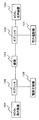
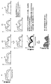
まず、図1を参照しながら、一般的なADSL伝送システムのシステム構成について説明する。 First, a system configuration of a general ADSL transmission system will be described with reference to FIG.
図1に示すように、ADSL伝送システムは、ADSL宅内装置(100)と、宅内電話機(101)と、宅内側のスプリッタ(102)と、ADSL局内装置(104)と、電話交換機(105)と、局内側のスプリッタ(106)と、を有して構成されている。 As shown in FIG. 1, the ADSL transmission system includes an ADSL in-home device (100), a home phone (101), a splitter (102) inside the home, an ADSL in-house device (104), and a telephone switch (105). , And a splitter (106) inside the station.
ADSL宅内装置(100)は、宅内側のスプリッタ(102)を介して線路(103)に接続される。また、宅内電話機(101)は、宅内側のスプリッタ(102)を介して線路(103)に接続される。 The ADSL in-home device (100) is connected to the line (103) via a splitter (102) inside the home. The home phone (101) is connected to the line (103) via the splitter (102) on the inside of the home.
ADSL局内装置(104)は、局内側のスプリッタ(106)を介して線路(103)に接続される。また、電話交換機(105)は、局内側のスプリッタ(106)を介して線路(103)に接続される。 The ADSL intra-station device (104) is connected to the line (103) via the splitter (106) inside the station. The telephone exchange (105) is connected to the line (103) via the splitter (106) inside the office.
スプリッタ(102、106)は、線路(103)内の信号を、通話信号と、ADSLによるデータ信号と、に分離するための装置であり、宅内側のスプリッタ(102)は、線路(103)内の信号が、通話信号の場合には、宅内電話機(101)側に接続され、線路(102)内の信号が、ADSLによるデータ信号の場合には、ADSL宅内装置(100)側に接続されることになる。また、局内側のスプリッタ(106)は、線路(103)内の信号が、通話信号の場合には、電話交換機(105)側に接続され、線路(103)内の信号が、ADSL信号の場合には、ADSL局内装置(104)側に接続されることになる。なお、ADSL局内装置(104)には、DSLAM(Digital Subscriber Line Multiplexer)を有し、そのDSLAMを介して、プロバイダからインターネットへと接続されることになる。なお、DSLAMは、アナログ信号として伝送されてきたデータをデジタル信号に変換し、プロバイダへと送信することになる。 The splitter (102, 106) is a device for separating a signal in the line (103) into a speech signal and a data signal by ADSL, and the splitter (102) inside the house is in the line (103). Is connected to the home phone (101) side when the signal is a call signal, and is connected to the ADSL home device (100) side when the signal in the line (102) is a data signal by ADSL. It will be. Further, the splitter (106) inside the station is connected to the telephone exchange (105) when the signal in the line (103) is a call signal, and the signal in the line (103) is an ADSL signal. Is connected to the ADSL in-station device (104) side. The ADSL intra-station apparatus (104) has a DSLAM (Digital Subscriber Line Multiplexer), and is connected to the Internet from the provider via the DSLAM. Note that the DSLAM converts data transmitted as an analog signal into a digital signal and transmits it to a provider.
なお、ADSL伝送システムは、DMT(Discrete Multi−Tone)と称される変復調方式を用いてデジタル信号をアナログ信号に変換して送信することになる。 The ADSL transmission system converts a digital signal into an analog signal using a modulation / demodulation method called DMT (Discrete Multi-Tone), and transmits the analog signal.
DMT方式は、256のキャリアにQAM(Quadrature Amplitude/Phase Modulation)による変調処理を行い、その変調したキャリアを、フーリエ逆変換を用いて多重化して送信する。そして、受信側は、多重化された信号を基にフーリエ変換を用いて各キャリアを抽出し、QAM変調された信号に復調処理を行い、データの高速伝送を行うことになる。 In the DMT scheme, modulation processing by QAM (Quadrature Amplitude / Phase Modulation) is performed on 256 carriers, and the modulated carriers are multiplexed and transmitted using inverse Fourier transform. The receiving side extracts each carrier using Fourier transform based on the multiplexed signal, performs demodulation processing on the QAM-modulated signal, and performs high-speed data transmission.
しかしながら、このDMT方式のADSL伝送システムは、ADSL用のケーブルがISDN用のケーブルと同一のケーブル束に含まれていると、ISDNケーブルからの影響により、ADSL回線の通信速度を低下させてしまうノイズを発生させる要因が存在することになる。中でも、ADSL回線への影響が大きいのは、ISDN回線からの漏話雑音である。そこで、ISDN用の回線とADSL用の回線とが同一ケーブル束に含まれないように構成することで、ノイズの発生を回避することも可能である。しかし、この場合には、オペレータに対する負担が大きすぎることになる。そこで、ISDN用の回線と、ADSL用の回線と、を同一ケーブルに束に含ませた際に発生する漏話雑音による通信速度の低下を回避し、伝送量を確保することを可能とする伝送方法が所望されている。 However, in this DMT ADSL transmission system, if the ADSL cable is included in the same cable bundle as the ISDN cable, noise that reduces the communication speed of the ADSL line due to the influence of the ISDN cable. There will be a factor that generates. Among them, the crosstalk noise from the ISDN line has a great influence on the ADSL line. Therefore, it is possible to avoid the generation of noise by configuring the ISDN line and the ADSL line so that they are not included in the same cable bundle. However, in this case, the burden on the operator is too great. Therefore, a transmission method capable of avoiding a decrease in communication speed due to crosstalk noise generated when an ISDN line and an ADSL line are included in a bundle in the same cable, and ensuring a transmission amount. Is desired.
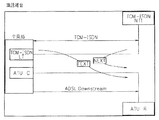
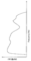
まず、図2を参照しながら、TCM方式のISDN回線を使用した際に、ADSL装置に発生する漏話雑音について説明する。なお、図2には、下り方向のデータ伝送を行っている際に、TCM−ISDN回線によるデータ伝送によりADSL装置の端末側の装置である、ATU−R(ADSL Transceiver Unit−Remote side)に発生する漏話雑音が示されている。 First, crosstalk noise generated in an ADSL apparatus when a TCM ISDN line is used will be described with reference to FIG. In FIG. 2, when data is transmitted in the downlink direction, it is generated in an ATU-R (ADSL Transceiver Unit-Remote side), which is a device on the terminal side of the ADSL device, by data transmission through the TCM-ISDN line. Crosstalk noise is shown.
TCM方式のISDN回線では、1.25msec毎に、上り方向と下り方向とのデータ伝送を交互に行っている。ADSL回線において下り方向のデータ伝送を行っている際に、TCM−ISDN回線が上り方向のデータ伝送を行った場合、TCM−ISDN回線からの減衰前の高出力の信号が、ADSL回線における減衰した信号に影響を及ぼし、端末ATU−R側に「NEXT」(Near End Cross Talk)、「近端漏話」が発生してしまうことになる。 In the TCM ISDN line, data transmission in the upstream direction and the downstream direction is alternately performed every 1.25 msec. When the TCM-ISDN line performs uplink data transmission while performing downlink data transmission on the ADSL line, the high-power signal before attenuation from the TCM-ISDN line is attenuated on the ADSL line. This affects the signal and causes “NEXT” (Near End Cross Talk) and “Near End Crosstalk” to occur on the terminal ATU-R side.
また、ADSL回線において下り方向のデータ伝送を行っている際に、TCM−ISDN回線が下り方向のデータ伝送を行った場合、TCM−ISDN回線の信号が減衰したADSL回線の信号に影響を及ぼし、端末側ATU−R側に「FEXT」(Far End Cross Talk)、「遠端漏話」が発生してしまうことになる。なお、同じ現象は、中央局側の装置であるATU−C(ADSL Tranceiver Unit−Center Side)においても発生することになる。 In addition, when the TCM-ISDN line performs downlink data transmission while performing downlink data transmission on the ADSL line, the TCM-ISDN line signal affects the attenuated ADSL line signal, "FEXT" (Far End Cross Talk) and "far end crosstalk" will occur on the terminal side ATU-R side. The same phenomenon also occurs in an ATU-C (ADSL Transceiver Unit-Center Side) which is a device on the central office side.
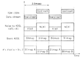
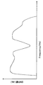
次に、図3を参照しながら、漏話雑音の雑音量について説明する。なお、図3には、漏話雑音の雑音量が示されている。図3に示すように、近端漏話発生時「NEXT」の雑音量は、遠端漏話発生時「FEXT」の雑音量よりも多いことになる。これは、TCM−ISDN回線からの減衰前の高出力の信号が、ADSL回線における減衰した信号に影響を及ぼすからである。この雑音量の差に注目し、近端漏話発生時「NEXT」と遠端漏話発生時「FEXT」とでデータの伝送量を切り替えて送信する方式が提案されている。この方式は、デュアルビットマップ方式と呼ばれ、図3に示すように、雑音量が所定の閾値より少ない遠端漏話「FEXT」の発生時には、データ量を多く送信し、雑音量が所定の閾値より多い近端漏話「NEXT」の発生時には、データ量を少なく送信することになる。 Next, the amount of crosstalk noise will be described with reference to FIG. FIG. 3 shows the amount of crosstalk noise. As shown in FIG. 3, the noise amount of “NEXT” when near-end crosstalk occurs is larger than the noise amount of “FEXT” when far-end crosstalk occurs. This is because the high-power signal before attenuation from the TCM-ISDN line affects the attenuated signal on the ADSL line. Paying attention to the difference in the amount of noise, a method has been proposed in which the transmission amount of data is switched between “NEXT” when near-end crosstalk occurs and “FEXT” when far-end crosstalk occurs. This method is called a dual bitmap method. As shown in FIG. 3, when a far-end crosstalk “FEXT” having a noise amount smaller than a predetermined threshold occurs, a large amount of data is transmitted, and the noise amount is a predetermined threshold value. When more near-end crosstalk “NEXT” occurs, a smaller amount of data is transmitted.
このように、TCM方式のISDN回線とADSL回線とが隣接するADSL伝送システムにおいては、雑音量が周期的に変化するため、上り方向と下り方向とで各キャリアのSNR(Signal to Noise Ratio)を測定し、該測定したSNRに従ってビット配分を求めるようになっている。 As described above, in the ADSL transmission system in which the TCM ISDN line and the ADSL line are adjacent to each other, the amount of noise periodically changes. Therefore, the SNR (Signal to Noise Ratio) of each carrier is increased in the uplink direction and the downlink direction. The bit allocation is determined according to the measured SNR.
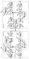
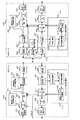
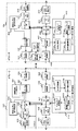
次に、図4を参照しながら、従来におけるADSL伝送システムについて説明する。 Next, a conventional ADSL transmission system will be described with reference to FIG.
<ATU−C300側の構成>
まず、ATU−C(300)側の構成について説明する。
<ATU-C300 side configuration>
First, the configuration on the ATU-C (300) side will be described.
ATU−C(300)の送信部には、上位装置から送られてくるデータに対してCRC(Cyclic Readuancy Check)符号を付加するCRCエラー処理部(315)と、CRC符号を付加したデータに対して、スクランブル処理を施し、リードソロモン方式のエラー訂正符号を付加するスクランブル処理及び誤り訂正部(scram&FEC(Forward Error Correction))(301)と、雑音レベルの変化するタイミングに応じて各キャリアの送信パワー配分、及び、ビット配分を切り替えて、キャリアにビット配分、及び、送信パワー配分をなすマッピング部(302)と、このマッピング出力である多値QAM(Quadrature Amplitude Modulation)信号を各キャリアで変調多重化するフーリエ逆変換部(303)と、この多重化出力をアナログ化して下りアナログ信号として送信するデジタル/アナログ変換部(304)と、を有している。 The transmission unit of the ATU-C (300) includes a CRC error processing unit (315) that adds a CRC (Cyclic Reliability Check) code to data sent from the host device, and a data that has the CRC code added thereto. The scramble process and error correction unit (scram & FEC (Forward Error Correction)) (301) for applying a scramble process and adding a Reed-Solomon error correction code, and the transmission power of each carrier according to the timing at which the noise level changes A mapping unit (302) that switches between allocation and bit allocation and performs bit allocation and transmission power allocation to a carrier, and a multilevel QAM (Quadrature Amplitude Modulation) signal that is the mapping output Inverse Fourier transform unit for modulating multiplexed with a carrier and (303), and the multiplexed output has a digital / analog converter for transmitting the analog data as a downlink analog signal (304), the.
また、ATU−C(300)の受信部には、ATU−R(400)から伝送されるアナログ信号をデジタル信号に変換するアナログ/デジタル変換部(305)と、このデジタル信号にフーリエ変換を施すフーリエ変換部(306)と、雑音レベルの変化するタイミングに応じてビット配分と送信パワー配分を切り替えて、伝送されてきた信号を復調するデマッピング部(307)と、スクランブル処理を施し、エラー訂正により正しいデータに戻す処理を行うスクランブル処理及び誤り訂正部(scram&FEC(Forward Error Correction))(308)と、予め決定された数式を用いて、データに付加されたCRC符号のチェック処理を行い、CRCエラー検出を行うCRCエラー検出部(314)と、を有している。 The ATU-C (300) receiving unit includes an analog / digital conversion unit (305) that converts an analog signal transmitted from the ATU-R (400) into a digital signal, and performs a Fourier transform on the digital signal. A Fourier transform unit (306), a demapping unit (307) that demodulates the transmitted signal by switching between bit distribution and transmission power distribution according to the timing of changing the noise level, and scrambles and performs error correction Using the scramble process and error correction unit (scram & FEC (Forward Error Correction)) (308) that performs processing to return to the correct data by the above and a predetermined formula, the CRC code added to the data is checked, CRC error detection unit (314) that performs error detection is doing.
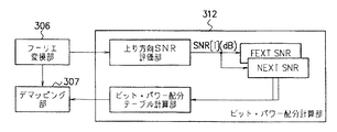
また、ATU−C(300)には、疑似ランダム信号発生部(310)と、雑音トーン発生部(311)と、ビット・パワー配分計算部(312)と、が設けられている。なお、図5に、ビット・パワー配分計算部(312)の詳細な構成を示す。 The ATU-C (300) is provided with a pseudo-random signal generator (310), a noise tone generator (311), and a bit power distribution calculator (312). FIG. 5 shows a detailed configuration of the bit power distribution calculation unit (312).
<ATU−R400側の構成>
次に、ATU−R(400)側の構成について説明する。
<ATU-R400 side configuration>
Next, the configuration on the ATU-R (400) side will be described.
ATU−R(400)の送信部には、上位装置から送られてくるデータに対してCRC(Cyclic Readuancy Check)符号を付加するCRCエラー処理部(415)と、CRC符号を付加したデータに対して、スクランブル処理を施し、リードソロモン方式のエラー訂正符号を付加するスクランブル処理及び誤り訂正部(scram&FEC(Forward Error Correction))(401)と、雑音レベルの変化するタイミングに応じて各キャリアの送信パワー配分及びビット配分を切り替えて、キャリアにビット配分及び送信パワー配分をなすマッピング部(402)と、このマッピング出力である多値QAM信号を各キャリアで変調多重化するフーリエ逆変換部(403)と、この多重化出力をアナログ化して上り信号として送信するデジタル/アナログ変換部(404)と、を有している。 The transmission unit of the ATU-R (400) includes a CRC error processing unit (415) for adding a CRC (Cyclic Reliability Check) code to data sent from the host device, and a data for which the CRC code is added. Scramble processing and error correction unit (scram & FEC (Forward Error Correction)) (401) that performs scramble processing and adds a Reed-Solomon error correction code, and the transmission power of each carrier according to the timing at which the noise level changes A mapping unit (402) that performs bit allocation and transmission power allocation to the carrier by switching between allocation and bit allocation, and a Fourier inverse transform unit (403) that modulates and multiplexes the multilevel QAM signal that is the mapping output on each carrier; , This multiplexed output Analog of digital / analog conversion unit to be transmitted as an uplink signal and (404), a has.
また、ATU−R(400)の受信部には、ATU−C(300)から伝送されるアナログ信号をデジタル信号に変換するアナログ/デジタル変換部(408)と、このデジタル信号にフーリエ変換を施すフーリエ変換部(407)と、雑音レベルの変化するタイミングに応じてビット配分と送信パワー配分を切り替えて、伝送されてきた信号を復調するデマッピング部(406)と、スクランブル処理を施し、エラー訂正により正しいデータに戻す処理を行うスクランブル処理及び誤り訂正部(scram&FEC(Forward Error Correction))(405)と、予め決定された数式を用いて、データに付加されたCRC符号のチェック処理を行い、CRCエラー検出を行うCRCエラー検出部(414)と、を有している。 The ATU-R (400) receiving unit has an analog / digital conversion unit (408) that converts an analog signal transmitted from the ATU-C (300) into a digital signal, and performs a Fourier transform on the digital signal. A Fourier transform unit (407), a demapping unit (406) that demodulates the transmitted signal by switching between bit distribution and transmission power distribution according to the timing of changing the noise level, and scrambles and performs error correction Using the scramble process and error correction unit (scram & FEC (Forward Error Correction)) (405) that performs processing for returning to the correct data by the above and a predetermined formula, the CRC code added to the data is checked, CRC error detection unit (414) for error detection is doing.
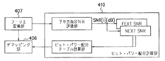
また、ATU−R(400)には、疑似ランダム信号発生部(409)と、ビット・パワー配分計算部(410)と、が設けられている。なお、図6に、ビット・パワー配分計算部(410)の詳細な構成を示す。 The ATU-R (400) is provided with a pseudo random signal generation unit (409) and a bit power distribution calculation unit (410). FIG. 6 shows a detailed configuration of the bit power distribution calculation unit (410).
図4に示すADSL伝送システムは、ISDNの下り方向送信時に、ATU−C(300)に、近端漏話「NEXT」が生じ、ATU−R(400)に、遠端漏話「FEXT」が生じることになる。また、ISDNの上り方向送信時に、ATU−C(300)に、遠端漏話「FEXT」が生じ、ATU−R(400)に、近端漏話「NEXT」が生じることになる。 In the ADSL transmission system shown in FIG. 4, near-end crosstalk “NEXT” occurs in ATU-C (300) and far-end crosstalk “FEXT” occurs in ATU-R (400) during downstream transmission of ISDN. become. Further, when ISDN is transmitted in the upstream direction, far end crosstalk “FEXT” occurs in ATU-C (300), and near end crosstalk “NEXT” occurs in ATU-R (400).
疑似ランダム信号発生部(310、409)は、上述した雑音環境下においてデータ伝送容量を確保するために、データ伝送に使用する各キャリアに対し、予め定められた疑似ランダム列をなすデータを順次割り当てた疑似ランダム信号を発生し、フーリエ逆変換部(303、403)にそれぞれ出力し、デジタル/アナログ変換部(304、404)を介して対向局側に出力することになる。 The pseudo-random signal generator (310, 409) sequentially assigns data forming a predetermined pseudo-random sequence to each carrier used for data transmission in order to secure the data transmission capacity in the above-described noise environment. Pseudo-random signals are generated and output to the inverse Fourier transform units (303, 403), respectively, and output to the opposite station side via the digital / analog conversion units (304, 404).
ビット・パワー配分計算部(312、410)は、対向局側の疑似ランダム信号発生部(409、310)により発生した疑似ランダム信号を用いてデータ伝送に用いる各キャリアに割り当てるビット配分、及び、各キャリアに使用する送信パワー配分を、近端漏話発生時と遠端漏話発生時とでそれぞれ求めることになる。そして、ビット・パワー配分計算部(312、410)は、近端漏話発生時と遠端漏話発生時とでそれぞれ求めたビット配分、及び、送信パワー配分を、自局側のデマッピング部(307、406)と、対向局側のマッピング部(302、402)と、にそれぞれ記憶することになる。 The bit power allocation calculation unit (312, 410) is configured to allocate a bit allocation to each carrier used for data transmission using the pseudo random signal generated by the pseudo random signal generation unit (409, 310) on the opposite station side, and The transmission power distribution to be used for the carrier is determined when near-end crosstalk occurs and when far-end crosstalk occurs. Then, the bit power allocation calculation unit (312 and 410) calculates the bit allocation and the transmission power allocation obtained when the near end crosstalk occurs and when the far end crosstalk occurs, respectively, and the demapping unit (307) on the local station side. , 406) and the opposite station side mapping section (302, 402).
次に、ビット・パワー配分計算部(312、410)が、ビット配分、及び、送信パワー配分を求める際の処理動作について説明する。なお、ATU−C(300)と、ATU−R(400)と、では同一の処理を行うことから、下り方向のビット配分、及び、送信パワー配分を求める処理についてのみ以下に説明する。 Next, processing operations when the bit power distribution calculation unit (312, 410) obtains bit distribution and transmission power distribution will be described. Since the ATU-C (300) and the ATU-R (400) perform the same process, only the process for obtaining the bit distribution in the downlink direction and the transmission power distribution will be described below.
まず、疑似ランダム信号発生部(310)は、キャリアに割り当てるビット配分、及び、各キャリアに使用する送信パワー配分を算出するためのトレーニング期間は、データ伝送に使用する各キャリアの振幅を、予め定められた疑似ランダム列に従って割り当てられる所定データのビットの並びに応じた振幅に変調し、該変調した各キャリアの振幅をフーリエ逆変換部(303)に出力することになる。 First, the pseudo random signal generation unit (310) predetermines the amplitude of each carrier used for data transmission in the training period for calculating the bit allocation to be assigned to the carrier and the transmission power allocation to be used for each carrier. Modulation is performed according to the sequence of bits of predetermined data assigned according to the pseudo-random sequence, and the modulated amplitude of each carrier is output to the inverse Fourier transform unit (303).
フーリエ逆変換部(303)は、振幅の変調された各キャリアに対しフーリエ逆変換を施し、各キャリアを足し合わせたデジタル形式で表される電圧値を出力する。また、デジタル/アナログ変換部(304)は、デジタル形式の電圧値を、実際の電圧値であるアナログ信号に変換して回線に出力することになる。 The Fourier inverse transform unit (303) performs an inverse Fourier transform on each carrier whose amplitude is modulated, and outputs a voltage value expressed in a digital format obtained by adding the carriers. The digital / analog converter (304) converts the digital voltage value into an analog signal that is an actual voltage value and outputs the analog signal to the line.
ATU−R(400)は、ATU−C(300)より送られたアナログ信号をアナログ/デジタル変換部(408)にてデジタル形式で表される電圧値に変換する。そして、フーリエ変換部(407)でデジタル形式の電圧値にフーリエ変換を施し、振幅の変調された各キャリアを取り出すことになる。 The ATU-R (400) converts the analog signal sent from the ATU-C (300) into a voltage value represented in a digital format by the analog / digital conversion unit (408). The Fourier transform unit (407) performs Fourier transform on the digital voltage value to extract each carrier whose amplitude is modulated.
フーリエ変換部(407)で取り出された各キャリアは、ビット・パワー配分計算部(410)に出力されることになる。 Each carrier extracted by the Fourier transform unit (407) is output to the bit power distribution calculation unit (410).
ビット・パワー配分計算部(410)は、下り方向SNR評価部にて各キャリアのSNR値をNEXT発生時と、FEXT発生時と、でそれぞれ複数算出し、各キャリアのSNRの平均値を算出する。 The bit power allocation calculation unit (410) calculates a plurality of SNR values for each carrier at the time of NEXT generation and at the time of FEXT generation by the downlink SNR evaluation unit, and calculates an average value of SNR of each carrier. .
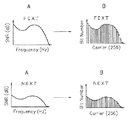
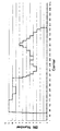
なお、図7に示すAは、下り方向SNR評価部にて評価されたFEXT発生時のSNRの平均値、及び、NEXT発生時のSNRの平均値を示すものである。 Note that A shown in FIG. 7 indicates the average value of the SNR when the FEXT occurs and the average value of the SNR when the NEXT occurs, which are evaluated by the downlink SNR evaluation unit.
図6に示す下り方向SNR評価部は、その算出したNEXT発生時のSNR平均値を、NEXT SNRに、また、FEXT発生時のSNR平均値を、FEXT SNRに、それぞれ保持することになる。 The downlink SNR evaluation unit shown in FIG. 6 holds the calculated SNR average value when NEXT occurs in NEXT SNR and the SNR average value when FEXT occurs in FEXT SNR, respectively.
また、ビット・パワー配分計算部は、測定した各キャリアのSNR平均値により雑音レベル毎に各キャリアのビット配分、及び、送信パワー配分を算出し、その算出したビット配分、及び、送信パワー配分をデマッピング部(406)に出力して記憶すると共に、マッピング部(402)に出力することになる。なお、図7に示すBは、下り方向SNR評価部で評価されたSNRの平均値に従って各キャリアのビット配分を決定している状態を概念的に示すものである。 Further, the bit power distribution calculation unit calculates the bit distribution and transmission power distribution of each carrier for each noise level based on the measured SNR average value of each carrier, and calculates the calculated bit distribution and transmission power distribution. The data is output to the demapping unit (406) and stored, and also output to the mapping unit (402). Note that B shown in FIG. 7 conceptually shows a state in which the bit allocation of each carrier is determined according to the average value of the SNR evaluated by the downlink SNR evaluation unit.
マッピング部(402)は、データ伝送に用いるキャリアに割り当てるビット配分、及び、キャリアに使用する送信パワー配分を算出するトレーニング期間は、ビット・パワー配分計算部(410)により算出されたビット配分、及び、送信パワー配分の情報を所定のキャリアに所定のビット数ずつ割り当て、該割り当てたビット配分、及び、送信パワー配分の情報を、フーリエ逆変換部(403)に出力することになる。 The mapping unit (402) uses the bit allocation calculated by the bit power allocation calculation unit (410) during the training period for calculating the bit allocation allocated to the carrier used for data transmission and the transmission power allocation used for the carrier, and The transmission power distribution information is allocated to a predetermined carrier by a predetermined number of bits, and the allocated bit distribution and transmission power distribution information are output to the inverse Fourier transform unit (403).
フーリエ逆変換部(403)は、マッピング部(402)から送られた所定のキャリアにフーリエ逆変換を施し、デジタル形式で表された電圧値を出力する。デジタル/アナログ変換部(404)は、デジタル形式で表された電圧値により実際の電圧値であるアナログ信号を生成し、回線に出力することになる。 The inverse Fourier transform unit (403) performs inverse Fourier transform on the predetermined carrier sent from the mapping unit (402), and outputs a voltage value expressed in digital format. The digital / analog conversion unit (404) generates an analog signal that is an actual voltage value based on the voltage value expressed in a digital format, and outputs the analog signal to the line.
ATU−C(300)は、ATU−R(400)より送られたアナログ信号をアナログ/デジタル変換部(305)にてデジタル形式で表される電圧値に変換する。そして、フーリエ変換部(306)でデジタル形式の電圧値にフーリエ変換を施し、振幅の変調された各キャリアを取り出す。 The ATU-C (300) converts the analog signal sent from the ATU-R (400) into a voltage value represented in a digital format by the analog / digital conversion unit (305). Then, the Fourier transform unit (306) performs Fourier transform on the digital voltage value, and takes out each carrier whose amplitude is modulated.
デマッピング部(307)は、所定のビット数ずつ割り当てられた所定のキャリアからビット配分、及び、送信パワー配分の情報を取り出し、該取り出したビット配分、及び、送信パワー配分の情報をマッピング部(302)に出力して記憶することになる。 The demapping unit (307) extracts information on bit distribution and transmission power distribution from a predetermined carrier assigned by a predetermined number of bits, and maps the extracted bit distribution and transmission power distribution information on the mapping unit ( 302) and stored.
マッピング部(302、402)は、上述した処理により算出された2種類のビット配分、及び、送信パワー配分を用いて、データ伝送時に発生する雑音レベルに応じたビット配分、及び、送信パワー配分を選択し、各キャリアにビット配分、及び、送信パワー配分を行う。また、デマッピング部(307、406)は、対向局で雑音レベルに応じてなされたビット配分、及び、送信パワー配分と同一のビット配分、及び、送信パワー配分を用いて、キャリアに割り当てられたデータを取り出すことになる。 The mapping unit (302, 402) uses the two types of bit allocation and transmission power allocation calculated by the above processing to perform bit allocation and transmission power allocation according to the noise level generated during data transmission. Select and perform bit allocation and transmission power allocation to each carrier. Further, the demapping units (307, 406) are allocated to the carrier by using the same bit allocation and transmission power allocation as the bit allocation and transmission power allocation made according to the noise level in the opposite station. Data will be retrieved.
なお、図4に示すADSL伝送システムは、ATU−C(300)側には、雑音同期トーン発生部(311)を有しており、ATU−R(400)側には、クロック検出部(411)と、ビット・パワー配分選択部(412)と、を有している。 The ADSL transmission system shown in FIG. 4 has a noise synchronization tone generator (311) on the ATU-C (300) side, and a clock detector (411) on the ATU-R (400) side. ) And a bit power distribution selection unit (412).
ATU−C(300)側のクロックは、雑音レベルの変化するタイミングに同期したクロックであり、この場合、雑音レベルの変化するタイミングは、既知であるとする。例えば、雑音がTCM方式のISDN回線からの漏話である場合、近端漏話と遠端漏話とが1.25msec毎に発生するため、各キャリアのSNRも1.25msec毎に変化する。そのため、ATU−C(300)の送信部では雑音レベルの変化するタイミングに同期した周期1.25msecで振幅に変化するクロックを受けてATU−R(400)の受信部に、当該クロックを送信することが必要となる。そこで、雑音同期トーン発生部(311)で当該クロックに同期して信号レベルを変化させた雑音同期トーン信号を発生させてATU−R(400)に送信している。より詳細には、雑音同期トーン発生部(311)は、雑音レベルの変化するタイミングに同期したクロックにより、所定のキャリアの振幅を、雑音レベルの変化するタイミングに同期して変化させ、フーリエ逆変換部(303)に出力している。 The clock on the ATU-C (300) side is a clock synchronized with the timing at which the noise level changes, and in this case, the timing at which the noise level changes is known. For example, when the noise is crosstalk from a TCM ISDN line, near-end crosstalk and far-end crosstalk occur every 1.25 msec, so that the SNR of each carrier also changes every 1.25 msec. Therefore, the transmission unit of the ATU-C (300) receives a clock that changes in amplitude at a period of 1.25 msec synchronized with the timing at which the noise level changes, and transmits the clock to the reception unit of the ATU-R (400). It will be necessary. Therefore, a noise synchronization tone generator (311) generates a noise synchronization tone signal whose signal level is changed in synchronization with the clock and transmits it to the ATU-R (400). More specifically, the noise synchronization tone generation unit (311) changes the amplitude of a predetermined carrier in synchronization with the timing at which the noise level changes by a clock synchronized with the timing at which the noise level changes, and performs inverse Fourier transform. Part (303).
クロック検出部(411)は、フーリエ変換部(407)により取り出された、所定キャリアの振幅の変化により雑音レベルの変化するタイミングを検出し、該検出した雑音レベルの変化するタイミングをビット・パワー配分選択部(412)に送信する。 The clock detection unit (411) detects the timing at which the noise level changes due to the change in the amplitude of the predetermined carrier extracted by the Fourier transform unit (407), and distributes the detected timing at which the noise level changes to the bit power distribution. It transmits to a selection part (412).
ビット・パワー配分選択部(412)は、クロック検出部(411)からの通知により、雑音レベルの変化するタイミングを認識し、マッピング部(402)に記憶した2種類のビット配分、及び、送信パワー配分のうち、雑音レベルに応じたデータ伝送を行うために使用するビット配分、及び、送信パワー配分の指定を行うことになる。また、ビット・パワー配分選択部(412)は、デマッピング部(406)に記憶した2種類のビット配分、及び、送信パワー配分のうち、データの復調に用いる、ATU−C(300)で雑音レベルに応じて使用されたビット配分、及び、送信パワー配分と同一のビット配分、及び、送信パワー配分の指定を行うことになる。 The bit power allocation selection unit (412) recognizes the timing at which the noise level changes in response to the notification from the clock detection unit (411), and stores the two types of bit allocations stored in the mapping unit (402) and the transmission power. Among the distributions, the bit distribution used to perform data transmission according to the noise level and the transmission power distribution are specified. The bit power distribution selection unit (412) uses the ATU-C (300) for noise demodulation among the two types of bit distributions and transmission power distributions stored in the demapping unit (406). The bit allocation used in accordance with the level and the same bit allocation and transmission power allocation as the transmission power allocation are designated.
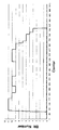
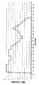
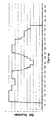
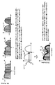
図8には、345のシンボルからなるハイパーフレームの構成が示されている。図8に示された点線Aより左側のシンボルは、ISDN回線からの漏話雑音が小さく(遠端漏話発生)、キャリアにビットを多く割り当てることができるシンボルである。また、図8に示された点線AとBとに挟まれたシンボルは、ISDN回線からの漏話雑音が大きく(遠端漏話発生)、キャリアに少しのビットしか割り当てることができないシンボルである。 FIG. 8 shows the configuration of a hyperframe composed of 345 symbols. The symbol on the left side of the dotted line A shown in FIG. 8 is a symbol that has low crosstalk noise from the ISDN line (far-end crosstalk occurs) and can allocate many bits to the carrier. In addition, the symbol between the dotted lines A and B shown in FIG. 8 is a symbol that has a large amount of crosstalk noise from the ISDN line (far-end crosstalk occurs) and can allocate only a few bits to the carrier.
ISDNからの遠端漏話発生タイミングに同期して0シンボルから送信を開始すると、図8に示されるように345番目のシンボルの受信タイミングとISDNからの漏話雑音の切り替わるタイミングとが同期することになる。従って、次の346番目のシンボルからISDNからの遠端漏話発生タイミングに同期してシンボルの送信を行うことが可能となる。ビット・パワー配分選択部(412)には、シンボルの送信順毎に2種類のビット配分、及び、送信パワー配分のうち、何れのビット配分、及び、送信パワー配分を使用すればよいのかが記憶されている。 When transmission is started from the 0th symbol in synchronization with the far-end crosstalk generation timing from the ISDN, the reception timing of the 345th symbol and the timing of switching of the crosstalk noise from the ISDN are synchronized as shown in FIG. . Therefore, it is possible to transmit symbols in synchronization with the far-end crosstalk occurrence timing from ISDN from the next 346th symbol. The bit power distribution selection unit (412) stores which bit distribution and transmission power distribution to use among the two types of bit distribution and transmission power distribution for each symbol transmission order. Has been.
なお、フーリエ逆変換部(303)には、疑似ランダム信号発生部(310)と、雑音同期トーン発生部(311)と、マッピング部(302)と、からの信号が出力されるが、それぞれの装置から出力される信号が同時にフーリエ逆変換部(303)に入力されることはない。即ち、フーリエ逆変換部(303)は、異なる時間で入力される信号にフーリエ逆変換を施し、デジタル/アナログ変換部(304)に出力することになる。なお、上述した各装置は図示しないシーケンサにより制御されている。このシーケンサの制御により疑似ランダム信号発生部(310)、雑音同期トーン発生部(311)は、所定の信号出力タイミングとなると、フーリエ逆変換部(303)に信号を出力することになる。また、フーリエ逆変換部(303)は、シーケンサにより次にどの装置から信号が入力されるのかを認識している。 The inverse Fourier transform unit (303) outputs signals from the pseudo random signal generation unit (310), the noise synchronization tone generation unit (311), and the mapping unit (302). Signals output from the apparatus are not simultaneously input to the inverse Fourier transform unit (303). That is, the inverse Fourier transform unit (303) performs inverse Fourier transform on signals input at different times and outputs the result to the digital / analog conversion unit (304). Each device described above is controlled by a sequencer (not shown). Under the control of the sequencer, the pseudo random signal generator (310) and the noise synchronization tone generator (311) output signals to the inverse Fourier transform unit (303) when the predetermined signal output timing is reached. The Fourier inverse transform unit (303) recognizes from which device the signal is input next by the sequencer.
なお、隣接回線に存在するTCM−ISDNからの漏話ノイズは、図3に示す、遠端漏話「FEXT」と、近端漏話「NEXT」と、が400Hz毎に発生し、ノイズの周期性が400Hzに同期していることから、従来のADSL伝送システムにおいては、400Hzのクロックを用いて、TCM−ISDNからの漏話ノイズの周期を予測し、周期的に発生するノイズによるエラーを回避することが可能であった。 In addition, the crosstalk noise from the TCM-ISDN existing in the adjacent line is generated as shown in FIG. 3 with the far end crosstalk “FEXT” and the near end crosstalk “NEXT” every 400 Hz, and the noise periodicity is 400 Hz. Therefore, in the conventional ADSL transmission system, it is possible to predict the period of crosstalk noise from the TCM-ISDN using a 400 Hz clock and avoid errors due to periodically generated noise. Met.
しかしながら、通信中にバースト的なノイズが短時間発生し、回線の接続を切断するという問題がある。従来のADSL伝送システムでは、様々な外部要因により、通信中に短時間のバースト的なノイズが発生した場合に、その短時間のバースト的なノイズのPSD(Power Specutrum Density)や周期を予測することは不可能であり、通常の初期化・トレーニング時間では、PSDを計測しきれず、データ伝送に用いるビット配分が不正確なものとなってしまうことになる。このため、不定期な周期雑音が発生した場合には、効率良くマルチキャリア伝送を行うことが困難となる。 However, there is a problem that burst noise occurs during communication for a short time, and the line connection is disconnected. In a conventional ADSL transmission system, when a short burst noise occurs during communication due to various external factors, a PSD (Power Spectrum Density) or period of the short burst noise is predicted. In the normal initialization / training time, the PSD cannot be measured and the bit allocation used for data transmission becomes inaccurate. For this reason, when irregular periodic noise occurs, it is difficult to perform multicarrier transmission efficiently.
なお、本発明より先に出願された技術文献として、周期的に変化する雑音の周期に応じてマルチキャリアの各キャリアの送信パワー配分を算出し、算出された送信パワー配分に基づいてデータ伝送をなすようにし、周期的に変化している雑音が発生している状態において、効率良くマルチキャリア伝送を行うようにしたものがある(例えば、特許文献1参照)。 In addition, as a technical document filed prior to the present invention, the transmission power distribution of each carrier of the multicarrier is calculated according to the period of periodically changing noise, and data transmission is performed based on the calculated transmission power distribution. In some cases, multi-carrier transmission is efficiently performed in a state where periodically changing noise is generated (see, for example, Patent Document 1).
また、雑音レベルの変化するタイミングが既知の雑音環境下において、第1及び第2の通信局相互間でマルチキャリアを用いたデータ伝送を行うものがある(例えば、特許文献2参照)。
しかしながら、上記特許文献1の技術は、周期的に変化する雑音が発生している状態において、効率良くマルチキャリア伝送を行うようにしたものであり、また、上記特許文献2の技術は、雑音レベルの変化するタイミングが既知の雑音環境下におけるマルチキャリア伝送であるため、上記特許文献1、2における技術は、不定期な周期雑音が発生した場合の回避対策については何ら考慮されたものではない。
However, the technique of
本発明は、上記事情に鑑みてなされたものであり、不定期な周期雑音が発生した場合でも、効率良くマルチキャリア伝送を行うことを可能とするマルチキャリア伝送装置及びマルチキャリア伝送方法を提供することを目的とするものである。 The present invention has been made in view of the above circumstances, and provides a multicarrier transmission apparatus and a multicarrier transmission method capable of efficiently performing multicarrier transmission even when irregular periodic noise occurs. It is for the purpose.
かかる目的を達成するために、本発明は以下の特徴を有することとする。 In order to achieve this object, the present invention has the following features.
本発明にかかるマルチキャリア伝送装置は、ビット配分を用いてデータ伝送を行うマルチキャリア伝送装置であって、通信回線に発生する周期雑音のSNR(Signal to Noise Ratio)を複数回測定するSNR測定手段と、SNR測定手段により測定したSNRの測定結果を基に、データ伝送に用いる各キャリアに割り当てるビット配分を測定結果毎に複数回算出するビット配分算出手段と、ビット配分算出手段により複数回算出したビット配分を比較し、各キャリア毎に最小のビット値を検出し、該検出した各キャリア毎の最小のビット値を基に、複数回算出したビット配分の各キャリア毎の最小のビット値を包含する最小ビット配分を算出する最小ビット配分算出手段と、最小ビット配分算出手段により算出した最小ビット配分を用いてデータ伝送を行う伝送手段と、を有することを特徴とするものである。 A multicarrier transmission apparatus according to the present invention is a multicarrier transmission apparatus that performs data transmission using bit allocation, and measures SNR (Signal to Noise Ratio) of periodic noise generated in a communication line a plurality of times. Based on the SNR measurement result measured by the SNR measurement means, the bit allocation calculation means for calculating the bit allocation to be assigned to each carrier used for data transmission a plurality of times for each measurement result, and the bit allocation calculation means calculated a plurality of times Compare bit allocation, detect the minimum bit value for each carrier, and include the minimum bit value for each carrier of the bit allocation calculated multiple times based on the detected minimum bit value for each carrier Minimum bit allocation calculating means for calculating the minimum bit allocation to be performed and the minimum calculated by the minimum bit allocation calculating means And transmission means for transmitting data using Tsu bets allocation, it is characterized in that it has a.
また、本発明にかかるマルチキャリア伝送装置は、ビット配分を用いてデータ伝送を行うマルチキャリア伝送装置であって、通信回線に発生する周期雑音のSNR(Signal to Noise Ratio)を複数回測定するSNR測定手段と、SNR測定手段により測定した複数回のSNRの測定結果を比較し、各周波数毎の最小のSNR値を検出し、該検出した各周波数毎の最小のSNR値を基に、複数回のSNRの測定結果の各周波数毎の最小のSNR値を包含する最小測定結果を算出する測定結果算出手段と、測定結果算出手段により算出した最小測定結果を基に、データ伝送に用いる各キャリアに割り当てるビット配分を算出するビット配分算出手段と、ビット配分算出手段により算出したビット配分を用いてデータ伝送を行う伝送手段と、を有することを特徴とするものである。 The multicarrier transmission apparatus according to the present invention is a multicarrier transmission apparatus that performs data transmission using bit allocation, and measures SNR (Signal to Noise Ratio) of periodic noise generated in a communication line a plurality of times. The measurement means and the measurement results of the SNR measured multiple times by the SNR measurement means are compared, the minimum SNR value for each frequency is detected, and multiple times based on the detected minimum SNR value for each frequency. The measurement result calculation means for calculating the minimum measurement result including the minimum SNR value for each frequency in the measurement results of the SNR and the carrier used for data transmission based on the minimum measurement result calculated by the measurement result calculation means. Data transmission is performed using a bit allocation calculation means for calculating the allocated bit allocation and the bit allocation calculated by the bit allocation calculation means. And transmission means, is characterized in that it has a.
また、本発明にかかるマルチキャリア伝送方法は、ビット配分を用いてデータ伝送を行う伝送装置におけるマルチキャリア伝送方法であって、通信回線に発生する周期雑音のSNR(Signal to Noise Ratio)を複数回測定するSNR測定工程と、SNR測定工程により測定したSNRの測定結果を基に、データ伝送に用いる各キャリアに割り当てるビット配分を測定結果毎に複数回算出するビット配分算出工程と、ビット配分算出工程により複数回算出したビット配分を比較し、各キャリア毎に最小のビット値を検出し、該検出した各キャリア毎の最小のビット値を基に、複数回算出したビット配分の各キャリア毎の最小のビット値を包含する最小ビット配分を算出する最小ビット配分算出工程と、最小ビット配分算出工程により算出した最小ビット配分を用いてデータ伝送を行う伝送工程と、を伝送装置が行うことを特徴とするものである。 The multi-carrier transmission method according to the present invention is a multi-carrier transmission method in a transmission apparatus that performs data transmission using bit allocation, and generates SNR (Signal to Noise Ratio) of periodic noise generated in a communication line a plurality of times. SNR measurement step for measuring, bit allocation calculation step for calculating a bit allocation to be assigned to each carrier used for data transmission a plurality of times for each measurement result based on the SNR measurement result measured in the SNR measurement step, and a bit allocation calculation step The bit allocations calculated multiple times by the above are compared, the minimum bit value is detected for each carrier, and the minimum bit value calculated for each carrier is calculated based on the detected minimum bit value for each carrier. Minimum bit allocation calculation step for calculating the minimum bit allocation including the bit values of the two bits, and the minimum bit allocation calculation A transmission step of transmitting data using the minimum bit allocation calculated by the degree, and is characterized in that performed by the transmission device.
また、本発明にかかるマルチキャリア伝送方法は、ビット配分を用いてデータ伝送を行う伝送装置におけるマルチキャリア伝送方法であって、通信回線に発生する周期雑音のSNR(Signal to Noise Ratio)を複数回測定するSNR測定工程と、SNR測定工程により測定した複数回のSNRの測定結果を比較し、各周波数毎の最小のSNR値を検出し、該検出した各周波数毎の最小のSNR値を基に、複数回のSNRの測定結果の各周波数毎の最小のSNR値を包含する最小測定結果を算出する測定結果算出工程と、測定結果算出工程により算出した最小測定結果を基に、データ伝送に用いる各キャリアに割り当てるビット配分を算出するビット配分算出工程と、ビット配分算出工程により算出したビット配分を用いてデータ伝送を行う伝送工程と、を、伝送装置が行うことを特徴とするものである。 The multi-carrier transmission method according to the present invention is a multi-carrier transmission method in a transmission apparatus that performs data transmission using bit allocation, and generates SNR (Signal to Noise Ratio) of periodic noise generated in a communication line a plurality of times. Compare the SNR measurement process to be measured with the SNR measurement results measured multiple times in the SNR measurement process, detect the minimum SNR value for each frequency, and based on the detected minimum SNR value for each frequency A measurement result calculation step for calculating a minimum measurement result including a minimum SNR value for each frequency in a plurality of SNR measurement results and a minimum measurement result calculated by the measurement result calculation step are used for data transmission. A bit allocation calculation process for calculating a bit allocation to be assigned to each carrier and a bit allocation calculated by the bit allocation calculation process are used. A transmission step of transmitting data, and is characterized in that performed by the transmission device.
本発明によれば、不定期な周期雑音が発生した場合でも、効率良くマルチキャリア伝送を行うことになり、突発的な雑音が発生した場合でも、高速な伝送速度を確保し、尚且つ、通信回線の品質を確保することが可能となる。 According to the present invention, even when irregular periodic noise occurs, multi-carrier transmission is performed efficiently. Even when sudden noise occurs, a high transmission speed is ensured and communication is performed. It is possible to ensure the line quality.
まず、図9を参照しながら、本実施形態におけるマルチキャリア伝送システムの特徴について説明する。 First, the characteristics of the multicarrier transmission system in the present embodiment will be described with reference to FIG.
本実施形態におけるマルチキャリア伝送システムは、ビット・パワー配分計算部(312、410)が、通信回線に発生する周期雑音のSNR(Signal to Noise Ratio)を複数回測定し、該測定したSNRの測定結果を基に、データ伝送に用いる各キャリアに割り当てるビット配分を測定結果毎に複数回算出する。そして、ビット・パワー配分計算部(312、410)は、その複数回算出したビット配分を比較し、各キャリア毎に最小のビット値を検出し、該検出した各キャリア毎の最小のビット値を基に、複数回算出したビット配分の各キャリア毎の最小のビット値を包含する最小ビット配分を算出し、該算出した最小ビット配分を、デマッピング部(307、406)、マッピング部(302、402)に送信する。デマッピング部(307、406)、マッピング部(302、402)は、ビット・パワー配分計算部(312、410)から送信された最小ビット配分を用いてデータ伝送を行う。 In the multicarrier transmission system according to the present embodiment, the bit power distribution calculation unit (312, 410) measures the SNR (Signal to Noise Ratio) of periodic noise generated in the communication line a plurality of times, and measures the measured SNR. Based on the result, the bit allocation allocated to each carrier used for data transmission is calculated a plurality of times for each measurement result. Then, the bit power distribution calculation unit (312, 410) compares the bit distribution calculated a plurality of times, detects the minimum bit value for each carrier, and determines the minimum bit value for each detected carrier. Based on this, the minimum bit allocation including the minimum bit value for each carrier of the bit allocation calculated a plurality of times is calculated, and the calculated minimum bit allocation is converted into a demapping unit (307, 406), a mapping unit (302, 402). The demapping unit (307, 406) and the mapping unit (302, 402) perform data transmission using the minimum bit allocation transmitted from the bit power allocation calculation unit (312, 410).
また、本実施形態におけるマルチキャリア伝送システムは、ビット・パワー配分計算部(312、410)が、通信回線に発生する周期雑音のSNR(Signal to Noise Ratio)を複数回測定し、該測定した複数回のSNRの測定結果を比較し、各周波数毎の最小のSNR値を検出し、該検出した各周波数毎の最小のSNR値を基に、各周波数毎の最小のSNR値を包含する最小測定結果を算出する。そして、ビット・パワー配分計算部(312、410)は、上記算出した最小測定結果を基に、データ伝送に用いる各キャリアに割り当てるビット配分を算出し、該算出したビット配分を、デマッピング部(307、406)、マッピング部(302、402)に送信する。デマッピング部(307、406)、マッピング部(302、402)は、ビット・パワー配分計算部(312、410)から送信された最小ビット配分を用いてデータ伝送を行う。 In the multicarrier transmission system according to the present embodiment, the bit power distribution calculation unit (312, 410) measures the SNR (Signal to Noise Ratio) of periodic noise generated in the communication line a plurality of times, and the measured plurality of The minimum SNR value for each frequency is detected and the minimum SNR value for each frequency is detected, and the minimum measurement including the minimum SNR value for each frequency is detected. Calculate the result. Based on the calculated minimum measurement result, the bit power allocation calculation unit (312, 410) calculates a bit allocation to be assigned to each carrier used for data transmission, and the calculated bit allocation is converted into a demapping unit ( 307, 406) and the mapping unit (302, 402). The demapping unit (307, 406) and the mapping unit (302, 402) perform data transmission using the minimum bit allocation transmitted from the bit power allocation calculation unit (312, 410).
これにより、本実施形態におけるマルチキャリア伝送システムは、不定期な周期雑音が発生した場合でも、効率良くマルチキャリア伝送を行うことが可能となる。以下、添付図面を参照しながら、本実施形態におけるマルチキャリア伝送システムについて説明する。 As a result, the multicarrier transmission system according to the present embodiment can efficiently perform multicarrier transmission even when irregular periodic noise occurs. Hereinafter, the multicarrier transmission system in the present embodiment will be described with reference to the accompanying drawings.
まず、図9を参照しながら、本実施形態におけるマルチキャリア伝送システムのシステム構成について説明する。 First, the system configuration of the multicarrier transmission system in the present embodiment will be described with reference to FIG.
本実施形態におけるマルチキャリア伝送システムは、図9に示すように、ビット・パワー配分計算部(312、410)が、SNR計算部(3121、4101)と、SNR値記憶部(3122、4102)と、最適ビットマップ計算部(3123、4103)と、を有して構成される。 As shown in FIG. 9, in the multicarrier transmission system according to the present embodiment, the bit power distribution calculation units (312 and 410), the SNR calculation units (3121 and 4101), the SNR value storage units (3122 and 4102), And an optimum bitmap calculation unit (3123, 4103).
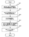
SNR計算部(3121、4101)は、周期雑音のSNR(Signal to Noise Ratio)を算出する部である。SNR値記憶部(3122、4102)は、SNR計算部(3121、4101)にて算出されたSNR値の算出結果を記憶する部である。最適ビットマップ計算部(3123、4103)は、SNR値記憶部(3122、4102)に記憶されたSNR値の算出結果を基に、データ伝送に用いる各キャリアに割り当てる最適なビット配分を算出する部である。以下、本実施形態におけるビット・パワー配分計算部(312、410)が、最適なビット配分を求める際の処理動作について説明する。なお、ATU−C(300)と、ATU−R(400)と、では同一の処理を行うことから、ATU−C(300)側のビット・パワー配分計算部(312)でビット配分を求める場合の処理動作についてのみ、図9〜図11を参照しながら、以下に説明する。 The SNR calculation unit (3121, 4101) is a unit that calculates an SNR (Signal to Noise Ratio) of periodic noise. The SNR value storage units (3122, 4102) are units that store the calculation results of the SNR values calculated by the SNR calculation units (3121, 4101). The optimum bitmap calculation unit (3123, 4103) calculates an optimum bit allocation to be assigned to each carrier used for data transmission based on the calculation result of the SNR value stored in the SNR value storage unit (3122, 4102). It is. Hereinafter, the processing operation when the bit power distribution calculation unit (312, 410) according to the present embodiment obtains the optimum bit distribution will be described. Since the ATU-C (300) and the ATU-R (400) perform the same processing, the bit power distribution calculation unit (312) on the ATU-C (300) side obtains the bit distribution. Only the processing operation will be described below with reference to FIGS.
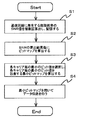
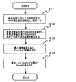
本実施形態におけるビット・パワー配分計算部(312)は、フーリエ変換部(306)で取り出されたキャリアを取得し、SNR計算部(3121)は、シンク・シンボルなどの送信信号を利用し、各キャリアのSNR値を雑音レベル毎に算出し、該算出したSNR値をSNR値記憶部(3122)に記憶することになる。 The bit power distribution calculation unit (312) in the present embodiment acquires the carrier extracted by the Fourier transform unit (306), and the SNR calculation unit (3121) uses a transmission signal such as a sync symbol, The SNR value of the carrier is calculated for each noise level, and the calculated SNR value is stored in the SNR value storage unit (3122).
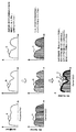
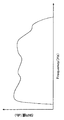
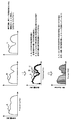
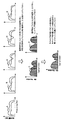
例えば、シンク・シンボルは、69ms毎に送信されるので、SNR計算部(3121)は、シンク・シンボルを利用することで、69ms毎に各キャリアのSNR値を雑音レベル毎に算出することになる。そして、SNR計算部(3121)は、69ms毎に算出された各キャリアのSNR値(図11のA、B、C)を、SNR値記憶部(3122)に記憶することになる(ステップS1)。これにより、SNR計算部(3121)は、各キャリアのSNR値を複数回算出することになり、図12〜図14に示す複数回のSNR値の算出結果をSNR値記憶部(3122)に記憶することになる。なお、以下の説明では、図11のAを、図12に示すSNR値の算出結果と仮定し、図11のBを図13に示すSNR値の算出結果と仮定し、図11のCを図14に示すSNR値の算出結果と仮定して説明する。 For example, since the sync symbol is transmitted every 69 ms, the SNR calculation unit (3121) uses the sync symbol to calculate the SNR value of each carrier for each noise level every 69 ms. . The SNR calculation unit (3121) stores the SNR values (A, B, and C in FIG. 11) of each carrier calculated every 69 ms in the SNR value storage unit (3122) (step S1). . As a result, the SNR calculation unit (3121) calculates the SNR value of each carrier a plurality of times, and the SNR value storage unit (3122) stores the calculation results of the SNR value a plurality of times shown in FIGS. Will do. In the following description, A in FIG. 11 is assumed to be the calculation result of the SNR value shown in FIG. 12, B in FIG. 11 is assumed to be the calculation result of the SNR value shown in FIG. 13, and C in FIG. Description will be made assuming that the calculation result of the SNR value shown in FIG.
次に、最適ビットマップ計算部(3123)は、SNR値記憶部(3122)に記憶した図11に示すA、B、CのSNR値の算出結果を基に、データ伝送に用いる各キャリアに割り当てるビット配分を、図11に示すA、B、CのSNR値の算出結果毎に算出し、図11に示すA、B、Cに示すビットマップを算出することになる(ステップS2)。これにより、最適ビットマップ計算部(3123)は、図15〜図17に示すビットマップを算出することになる。なお、図15は、図12に示すSNRの値の算出結果を基に算出したビットマップを示し、また、図16は、図13に示すSNRの値の算出結果を基に算出したビットマップを示し、また、図17は、図14に示すSNRの値の算出結果を基に算出したビットマップを示している。 Next, the optimum bitmap calculation unit (3123) assigns to each carrier used for data transmission based on the calculation results of the SNR values of A, B, and C shown in FIG. 11 stored in the SNR value storage unit (3122). Bit allocation is calculated for each calculation result of SNR values of A, B, and C shown in FIG. 11, and bitmaps shown in A, B, and C shown in FIG. 11 are calculated (step S2). As a result, the optimum bitmap calculation unit (3123) calculates the bitmaps shown in FIGS. 15 shows a bitmap calculated based on the calculation result of the SNR value shown in FIG. 12, and FIG. 16 shows a bitmap calculated based on the calculation result of the SNR value shown in FIG. FIG. 17 shows a bitmap calculated based on the SNR value calculation result shown in FIG.
次に、最適ビットマップ計算部(3123)は、ステップS2において算出したA、B、Cに示すビットマップの算出結果を比較し、各キャリアにおける最小のビット値を選択し、該選択した各キャリア毎の最小のビット値を基に、A、B、Cの各キャリア毎の最小のビット値を包含する最小のビットマップを算出することになる(ステップS3)。これにより、最適ビットマップ計算部(3123)は、図15〜図17に示す複数回算出したビットマップの各キャリア毎の最小のビット値を包含する図18に示す最小ビットマップを算出することになり、最適な伝送速度を確保し、尚且つ、バースト・ノイズが発生してもエラー・リンクダウンを発生させないビットマップを算出することが可能となる。 Next, the optimum bitmap calculation unit (3123) compares the calculation results of the bitmaps shown in A, B, and C calculated in step S2, selects the minimum bit value in each carrier, and selects each selected carrier. Based on the minimum bit value for each, a minimum bit map including the minimum bit value for each carrier of A, B, and C is calculated (step S3). Thereby, the optimum bitmap calculation unit (3123) calculates the minimum bitmap shown in FIG. 18 including the minimum bit value for each carrier of the bitmaps calculated a plurality of times shown in FIGS. Therefore, it is possible to calculate a bitmap that ensures an optimum transmission rate and that does not cause an error link down even if burst noise occurs.
次に、最適ビットマップ計算部(3123)は、図18に示すビットマップ算出結果を、デマッピング部(307)と、マッピング部(302)と、に送信することになる。デマッピング部(307)と、マッピング部(302)と、は、最適ビットマップ計算部(3123)から送信された図18に示すビットマップ算出結果を基に、データ伝送を行うことになる(ステップS4)。 Next, the optimal bitmap calculation unit (3123) transmits the bitmap calculation result shown in FIG. 18 to the demapping unit (307) and the mapping unit (302). The demapping unit (307) and the mapping unit (302) perform data transmission based on the bitmap calculation result shown in FIG. 18 transmitted from the optimum bitmap calculation unit (3123) (step S4).
これにより、本実施形態におけるマルチキャリア伝送システムは、図18に示すビットマップ算出結果を用いてデータ伝送を行うことになり、バースト・ノイズが存在する雑音環境下でも高速な伝送速度を確保し、尚且つ、回線の品質を確保することが可能となる。なお、ビットマップを変更するには、相手端末となるATU−R(400)に対して、ビットマップを送信する必要がある。従って、本実施形態におけるマルチキャリア伝送システムは、従来と同様に、任意のタイミングで、ATU−C(300)からATU−R(400)に対してビットマップを送信し、また、ATU−R(400)からATU−C(300)に対してビットマップを送信し、ATU−C(300)と、ATU−R(400)と、の両端末間で、同時にビットマップを変更することで、データ伝送を継続することになる。 As a result, the multicarrier transmission system in the present embodiment performs data transmission using the bitmap calculation result shown in FIG. 18, and ensures a high transmission rate even in a noise environment where burst noise exists, Moreover, it is possible to ensure the quality of the line. In order to change the bitmap, it is necessary to transmit the bitmap to the ATU-R (400) as the counterpart terminal. Therefore, the multicarrier transmission system according to the present embodiment transmits a bitmap from the ATU-C (300) to the ATU-R (400) at an arbitrary timing, as in the prior art, and the ATU-R ( 400) from ATU-C (300) to ATU-C (300), and by simultaneously changing the bitmap between both terminals of ATU-C (300) and ATU-R (400), data Transmission will continue.
このように、本実施形態におけるマルチキャリア伝送システムは、バースト的に発生し、かつ、短時間で消えてしまうノイズに対し、定期的にSNR値の計測を行い、該定期的に計測したSNR値の測定結果を基に、バースト・ノイズ環境下で、最適な伝送速度を確保し、かつ、バースト・ノイズによるエラー・リンクダウンを回避した最適なビットマップ値を計算する。そして、該計算した最適なビットマップ値を用いてデータ伝送を行うことで、バースト的なノイズが発生した場合でも、効率良くマルチキャリア伝送を行うことが可能となる。 As described above, the multicarrier transmission system according to the present embodiment periodically measures the SNR value with respect to the noise that occurs in a burst and disappears in a short time, and the SNR value measured periodically is measured. Based on these measurement results, an optimum bit map value is calculated that ensures an optimum transmission speed and avoids error link down due to burst noise in a burst noise environment. By performing data transmission using the calculated optimum bitmap value, it is possible to efficiently perform multicarrier transmission even when burst noise occurs.
次に、第2の実施形態について説明する。
第1の実施形態におけるマルチキャリア伝送システムは、ビット・パワー配分計算部(312、410)が、SNR値記憶部(3122、4102)に記憶した図12〜図14に示すSNR値の算出結果を基に、図15〜図17に示すビット配分を算出したが、第2の実施形態におけるマルチキャリア伝送システムは、ビット・パワー配分計算部(312、410)が、SNR値記憶部(3122、4102)に記憶した図12〜図14に示すSNR値の算出結果を基に、各周波数毎の最小のSNR値を検出し、該検出した各周波数毎の最小のSNR値を基に、図12〜図14に示す複数回のSNR値の算出結果の各周波数毎の最小のSNR値を包含するSNR値を算出することを特徴とするものである。以下、図9、図19、図20を参照しながら、第2の実施形態におけるマルチキャリア伝送システムについて説明する。なお、ATU−C(300)と、ATU−R(400)と、では同一の処理を行うことから、ATU−C(300)側のビット・パワー配分計算部(312)でビット配分を求める場合の処理動作についてのみ以下に説明する。
Next, a second embodiment will be described.
In the multicarrier transmission system according to the first embodiment, the bit power distribution calculation units (312 and 410) store the SNR value calculation results shown in FIGS. 12 to 14 stored in the SNR value storage units (3122 and 4102). Based on the bit allocation shown in FIGS. 15 to 17, the multi-carrier transmission system according to the second embodiment is configured such that the bit power allocation calculation unit (312 and 410) is the SNR value storage unit (3122 and 4102). ) Stored in FIG. 12 to FIG. 14, the minimum SNR value for each frequency is detected, and based on the detected minimum SNR value for each frequency, FIG. The SNR value including the minimum SNR value for each frequency in the calculation result of the SNR value of a plurality of times shown in FIG. 14 is calculated. Hereinafter, the multicarrier transmission system according to the second embodiment will be described with reference to FIGS. 9, 19, and 20. Since the ATU-C (300) and the ATU-R (400) perform the same processing, the bit power distribution calculation unit (312) on the ATU-C (300) side obtains the bit distribution. Only the processing operation will be described below.
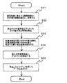
まず、SNR計算部(3121)は、第1の実施形態と同様に、シンク・シンボルなどの送信信号を利用し、各キャリアのSNR値を複数回算出することになり、図20に示すA、B、CのSNR値の算出結果をSNR値記憶部(3122)に記憶することになる(ステップS11)。これにより、SNR計算部(3121)は、図12〜図14に示す複数回のSNR値の算出結果をSNR値記憶部(3122)に記憶することになる。 First, similarly to the first embodiment, the SNR calculation unit (3121) uses a transmission signal such as a sync symbol to calculate the SNR value of each carrier a plurality of times. The calculation results of the B and C SNR values are stored in the SNR value storage unit (3122) (step S11). As a result, the SNR calculation unit (3121) stores the calculation results of the SNR values a plurality of times shown in FIGS. 12 to 14 in the SNR value storage unit (3122).
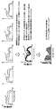
次に、最適ビットマップ計算部(3123)は、SNR値記憶部(3122)に記憶した図20に示すA、B、CのSNR値の算出結果を比較し、各周波数毎の最小のSNR値を選択し、その各周波数毎に選択した最小のSNR値を基に、図20に示すA、B、Cの測定結果における各周波数毎の最小のSNR値を包含する最小測定結果を算出することになる(ステップS12)。そして、最適ビットマップ計算部(3123)は、ステップS12において算出した最小測定結果を基に、データ伝送に用いる各キャリアに割り当てる図18に示すようなビットマップを算出することになる(ステップS13)。 Next, the optimum bitmap calculation unit (3123) compares the calculation results of the SNR values of A, B, and C shown in FIG. 20 stored in the SNR value storage unit (3122), and the minimum SNR value for each frequency. And the minimum measurement result including the minimum SNR value for each frequency in the measurement results of A, B, and C shown in FIG. 20 is calculated based on the minimum SNR value selected for each frequency. (Step S12). Then, the optimum bitmap calculation unit (3123) calculates a bitmap as shown in FIG. 18 assigned to each carrier used for data transmission based on the minimum measurement result calculated in step S12 (step S13). .
このように、最適ビットマップ計算部(3123)は、図12〜図14に示す複数回のSNR値の算出結果を基に、各周波数における最小のSNR値を選択し、該各周波数毎に選択した最小のSNR値の測定結果を算出し、該算出した最小のSNR値の測定結果を基に、図18に示すようなビットマップを算出することになり、最適ビットマップ計算部(3123)は、最適な伝送速度を確保し、尚且つ、バースト・ノイズが発生してもエラー・リンクダウンを発生させない最適なビットマップを算出することになる。そして、最適ビットマップ計算部(3123)は、図18に示すビットマップ算出結果を、デマッピング部(307)と、マッピング部(302)と、に送信することになる。そして、デマッピング部(307)と、マッピング部(302)と、は、最適ビットマップ計算部(3123)から送信された図18に示すビットマップ算出結果を基に、データ伝送を行うことになる(ステップS14)。これにより、本実施形態におけるマルチキャリア伝送システムは、バースト・ノイズが存在する雑音環境下でも、図18に示すビットマップ算出結果を用いてデータ伝送を行うことで、高速な伝送速度を確保し、尚且つ、回線の品質を確保することが可能となる。 As described above, the optimum bitmap calculation unit (3123) selects the minimum SNR value at each frequency based on the calculation results of the SNR values obtained a plurality of times shown in FIGS. The measurement result of the minimum SNR value is calculated, and a bitmap as shown in FIG. 18 is calculated based on the measurement result of the calculated minimum SNR value. The optimum bitmap calculation unit (3123) Thus, an optimum bit map that secures an optimum transmission rate and does not cause an error link down even when burst noise occurs is calculated. Then, the optimum bitmap calculation unit (3123) transmits the bitmap calculation result shown in FIG. 18 to the demapping unit (307) and the mapping unit (302). Then, the demapping unit (307) and the mapping unit (302) perform data transmission based on the bitmap calculation result shown in FIG. 18 transmitted from the optimum bitmap calculation unit (3123). (Step S14). Thereby, the multicarrier transmission system in the present embodiment secures a high transmission speed by performing data transmission using the bitmap calculation result shown in FIG. 18 even in a noise environment where burst noise exists, Moreover, it is possible to ensure the quality of the line.
次に、第3の実施形態について説明する。
第3の実施形態におけるマルチキャリア伝送システムは、第1の実施形態におけるマルチキャリア伝送システムにおいて、SNR値記憶部(3122)に記憶した複数回のSNRの算出結果の中から、所定のSNR基準値以下となったSNR値の周波数領域を有するSNRの算出結果を検出し、該検出したSNRの算出結果を基に、図18に示すようなデータ伝送に最適なビットマップを算出することを特徴とするものである。以下、図9、図21、図22を参照しながら、第3の実施形態におけるマルチキャリア伝送システムについて説明する。
Next, a third embodiment will be described.
The multi-carrier transmission system according to the third embodiment is the same as the multi-carrier transmission system according to the first embodiment, except that a predetermined SNR reference value is selected from a plurality of SNR calculation results stored in the SNR value storage unit (3122). A calculation result of an SNR having a frequency region of an SNR value that is as follows is detected, and an optimum bitmap for data transmission as shown in FIG. 18 is calculated based on the detected calculation result of the SNR. To do. Hereinafter, the multicarrier transmission system according to the third embodiment will be described with reference to FIGS. 9, 21, and 22.
まず、SNR計算部(3121)は、第1の実施形態と同様に、シンク・シンボルなどの送信信号を利用し、各キャリアのSNR値を複数回算出することになり、図22に示すA〜EのSNR値の算出結果をSNR値記憶部(3122)に記憶することになる(ステップS21)。 First, similarly to the first embodiment, the SNR calculation unit (3121) uses a transmission signal such as a sync symbol to calculate the SNR value of each carrier a plurality of times. The calculation result of the SNR value of E is stored in the SNR value storage unit (3122) (step S21).
次に、最適ビットマップ計算部(3123)は、SNR値記憶部(3122)に記憶した図22に示すA〜EのSNR値の算出結果の中から、所定のSNR基準値以下となったSNR値の周波数領域を有する図22に示すC、DのSNRの算出結果を検出することになる(ステップS22)。これにより、最適ビットマップ計算部(3123)は、SNR値記憶部(3122)に記憶した複数回のSNR値の算出結果の中から、図13、図14に示すようなSNR値が大きく変動した算出結果のみを選択することが可能となり、最適ビットマップ計算部(3123)は、その選択した算出結果を基に、データ伝送に用いる各キャリアに割り当てるビット配分を、算出結果毎に算出し、図16、図17に示すビットマップを算出することになる(ステップS23)。 Next, the optimal bitmap calculation unit (3123), among the calculation results of the SNR values of A to E shown in FIG. 22 stored in the SNR value storage unit (3122), has an SNR that is equal to or less than a predetermined SNR reference value. The calculation result of the SNR of C and D shown in FIG. 22 having the frequency domain of values is detected (step S22). As a result, the optimum bitmap calculation unit (3123) has greatly changed the SNR values as shown in FIGS. 13 and 14 from the calculation results of the SNR values stored in the SNR value storage unit (3122) a plurality of times. Only the calculation result can be selected, and the optimum bitmap calculation unit (3123) calculates the bit allocation to be assigned to each carrier used for data transmission for each calculation result based on the selected calculation result. 16, the bitmap shown in FIG. 17 is calculated (step S23).
次に、最適ビットマップ計算部(3123)は、図16、図17に示すビットマップを比較し、各キャリアにおける最小のビット値を選択し、該選択した各キャリア毎の最小のビット値を基に、図18に示すビットマップを算出することになる(ステップS24)。 Next, the optimum bitmap calculation unit (3123) compares the bitmaps shown in FIGS. 16 and 17, selects the minimum bit value in each carrier, and based on the minimum bit value for each selected carrier. Then, the bitmap shown in FIG. 18 is calculated (step S24).
このように、最適ビットマップ計算部(3123)は、SNR値記憶部(3122)に記憶した複数回のSNR値の算出結果の中から、SNR値が大きく変動した図13、図14に示す算出結果のみを検出し、該検出した図13、図14に示すSNRの算出結果を基に、図16、図17に示すビットマップを算出し、該算出したビットマップの各キャリア毎の最小のビット値を包含する図18に示す最小ビットマップを算出することになり、最適な伝送速度を確保し、尚且つ、バースト・ノイズが発生してもエラー・リンクダウンを発生させないビットマップを算出することが可能となる。 As described above, the optimum bitmap calculation unit (3123) calculates the SNR values greatly varied from the calculation results of the SNR values stored in the SNR value storage unit (3122), as shown in FIGS. Only the result is detected, and the bitmap shown in FIGS. 16 and 17 is calculated based on the detected SNR calculation results shown in FIGS. 13 and 14, and the minimum bit for each carrier of the calculated bitmap is calculated. The minimum bitmap shown in FIG. 18 including the values is calculated, and a bitmap that ensures an optimum transmission rate and does not cause an error link down even if burst noise occurs is calculated. Is possible.
次に、第4の実施形態について説明する。
第4の実施形態におけるマルチキャリア伝送システムは、第2の実施形態におけるマルチキャリア伝送システムにおいて、SNR値記憶部(3122)に記憶した複数回のSNRの算出結果の中から、所定のSNR基準値以下となったSNR値の周波数領域を有するSNRの算出結果を検出し、該検出したSNRの算出結果を基に、図18に示すようなデータ伝送に最適なビットマップを算出することを特徴とするものである。以下、図9、図23、図24を参照しながら、第4の実施形態におけるマルチキャリア伝送システムについて説明する。
Next, a fourth embodiment will be described.
The multi-carrier transmission system according to the fourth embodiment is the same as the multi-carrier transmission system according to the second embodiment except that a predetermined SNR reference value is selected from a plurality of SNR calculation results stored in the SNR value storage unit (3122). A calculation result of an SNR having a frequency region of an SNR value that is as follows is detected, and an optimum bitmap for data transmission as shown in FIG. 18 is calculated based on the detected calculation result of the SNR. To do. Hereinafter, the multicarrier transmission system according to the fourth embodiment will be described with reference to FIGS. 9, 23, and 24.
まず、SNR計算部(3121)は、第2の実施形態と同様に、シンク・シンボルなどの送信信号を利用し、各キャリアのSNR値を複数回算出することになり、図24に示すA〜EのSNR値の算出結果をSNR値記憶部(3122)に記憶することになる(ステップS31)。 First, similarly to the second embodiment, the SNR calculation unit (3121) uses a transmission signal such as a sync symbol to calculate the SNR value of each carrier a plurality of times. The calculation result of the SNR value of E is stored in the SNR value storage unit (3122) (step S31).
次に、最適ビットマップ計算部(3123)は、SNR値記憶部(3122)に記憶した図24に示すA〜EのSNR値の算出結果の中から、所定のSNR基準値以下となったSNR値の周波数領域を有する図24に示すC、DのSNRの算出結果を検出することになる(ステップS32)。これにより、最適ビットマップ計算部(3123)は、SNR値記憶部(3122)に記憶した複数回のSNR値の算出結果の中から、図13、図14に示すようなSNR値が大きく変動した算出結果のみを選択することが可能となり、最適ビットマップ計算部(3123)は、図13、図14に示すSNR値の算出結果を基に、各周波数における最小のSNR値を選択し、該各周波数毎に選択した最小のSNR値を基に、図13、図14に示すSNRの測定結果における各周波数毎の最小のSNR値を包含する最小測定結果を算出する(ステップS33)。そして、最適ビットマップ計算部(3123)は、上記算出した最小のSNR値の測定結果を基に、図18に示すようなビットマップを算出することになる(ステップS34)。 Next, the optimal bitmap calculation unit (3123), among the calculation results of the SNR values of A to E shown in FIG. 24 stored in the SNR value storage unit (3122), has an SNR that is equal to or less than a predetermined SNR reference value. The calculation result of the SNR of C and D shown in FIG. 24 having the frequency domain of values is detected (step S32). As a result, the optimum bitmap calculation unit (3123) has greatly changed the SNR values as shown in FIGS. 13 and 14 from the calculation results of the SNR values stored in the SNR value storage unit (3122) a plurality of times. Only the calculation result can be selected, and the optimum bitmap calculation unit (3123) selects the minimum SNR value at each frequency based on the calculation results of the SNR values shown in FIGS. Based on the minimum SNR value selected for each frequency, the minimum measurement result including the minimum SNR value for each frequency in the SNR measurement results shown in FIGS. 13 and 14 is calculated (step S33). Then, the optimum bitmap calculation unit (3123) calculates a bitmap as shown in FIG. 18 based on the measurement result of the calculated minimum SNR value (step S34).
このように、最適ビットマップ計算部(3123)は、SNR値記憶部(3122)に記憶した複数回のSNR値の算出結果の中から、SNR値が大きく変動した図13、図14の算出結果のみを検出し、該検出した図13、図14に示すSNRの算出結果を比較し、各周波数における最小のSNR値を選択し、該各周波数毎に選択した最小のSNR値の測定結果を算出し、該算出した最小のSNR値の測定結果を基に、図18に示すようなビットマップを算出することになり、最適な伝送速度を確保し、尚且つ、バースト・ノイズが発生してもエラー・リンクダウンを発生させないビットマップを算出することが可能となる。なお、SNR値が大きく変動した算出結果のみを選択するための判断材料となる所定のSNR基準値は、任意に設定することが可能である。 As described above, the optimum bitmap calculation unit (3123) calculates the calculation results of FIGS. 13 and 14 in which the SNR value greatly fluctuates from the calculation results of the SNR values stored in the SNR value storage unit (3122). 13 are compared, the SNR calculation results shown in FIGS. 13 and 14 are compared, the minimum SNR value at each frequency is selected, and the measurement result of the minimum SNR value selected for each frequency is calculated. Then, based on the measurement result of the calculated minimum SNR value, a bitmap as shown in FIG. 18 is calculated, and an optimum transmission rate is ensured and even if burst noise occurs. It is possible to calculate a bitmap that does not cause an error link down. It should be noted that the predetermined SNR reference value used as a judgment material for selecting only the calculation result in which the SNR value greatly fluctuates can be arbitrarily set.
次に、第5の実施形態について説明する。
第3、第4の実施形態においては、最適ビットマップ計算部(3123)が、SNR値記憶部(3122)に記憶した複数回のSNR値の算出結果の中から、SNR値が大きく変動した図13、図14に示す算出結果のみを検出することとしたが、第5の実施形態は、SNR計算部(3121)が、図13、図14に示すSNR値が大きく変動したSNR値の算出結果のみをSNR値記憶部(3122)に記憶することを特徴とする。以下、図9、図25を参照しながら、第5の実施形態におけるマルチキャリア伝送システムについて説明する。
Next, a fifth embodiment will be described.
In the third and fourth embodiments, the optimum bitmap calculation unit (3123) has a SNR value greatly fluctuated from a plurality of SNR value calculation results stored in the SNR value storage unit (3122). 13, only the calculation result shown in FIG. 14 is detected, but in the fifth embodiment, the SNR calculation unit (3121) calculates the SNR value in which the SNR value shown in FIG. 13 and FIG. Is stored in the SNR value storage unit (3122). Hereinafter, the multicarrier transmission system in the fifth embodiment will be described with reference to FIGS. 9 and 25.
まず、SNR計算部(3121)は、シンク・シンボルなどの送信信号を利用し、各キャリアのSNR値を雑音レベル毎に算出し、雑音レベル毎のSNRの算出結果を生成することになる。そして、SNR計算部(3121)は、その生成した各雑音レベル毎のSNRの算出結果と、各雑音レベル毎のSNR基準値から構成されるSNR基準結果と、を比較し、各雑音レベル毎のSNRの算出結果の中に、SNR基準値以下となったSNR値があるか否かを判断し、SNR基準値以下となったSNR値がある周波数領域を有する図25に示すC、DのSNRの算出結果のみを検出することになる。そして、その検出した図25に示すC、DのSNRの算出結果のみをSNR値記憶部(3122)に記憶することになる(ステップS41)。これにより、SNR計算部(3121)が算出した図25に示すA〜EのSNR値の算出結果を全てSNR値記憶部(3122)に記憶することなく、図25に示すC、DのSNR値が大きく変動したSNR値の算出結果のみをSNR値記憶部(3122)に記憶することが可能となる。これにより、SNR計算部(3121)は、図13、図14に示すSNR値が大きく変動したSNR値の算出結果のみをSNR値記憶部(3122)に記憶することになり、SNR値記憶部(3122)に記憶するSNR値の算出結果の情報量を少なくし、SNR値記憶部(3122)の記憶容量を低減させることが可能となる。そして、最適ビットマップ計算部(3123)は、SNR値記憶部(3122)に記憶された図25に示すC、DのSNR値の算出結果を基に、各周波数における最小のSNR値を選択し、該各周波数毎に選択した最小のSNR値を基に、図25に示すC、DのSNRの測定結果における各周波数毎の最小のSNR値を包含する最小測定結果を算出することになる(ステップS42)。従って、最適ビットマップ計算部(3123)は、SNR値記憶部(3122)に記憶された、図13、図14に示すSNR値が大きく変動したSNR値の算出結果のみを基に、最小測定結果を算出することになるため、SNR値の算出結果の情報量を抑えて最少測定結果を算出することになり、最適ビットマップ計算部(3122)は、最少測定結果を算出する際の処理を速くすることが可能となる。そして、最適ビットマップ計算部(3123)は、上記算出した最小のSNR値の測定結果を基に、図18に示すようなビットマップを算出することになる(ステップS43)。 First, the SNR calculation unit (3121) uses a transmission signal such as a sync symbol, calculates the SNR value of each carrier for each noise level, and generates an SNR calculation result for each noise level. Then, the SNR calculation unit (3121) compares the generated SNR calculation result for each noise level with the SNR reference result composed of the SNR reference value for each noise level, and for each noise level. It is determined whether or not there is an SNR value that is equal to or lower than the SNR reference value in the SNR calculation result, and the SNRs of C and D shown in FIG. Only the calculation result is detected. Then, only the detected C and D SNR calculation results shown in FIG. 25 are stored in the SNR value storage unit (3122) (step S41). Thus, the SNR values of C and D shown in FIG. 25 are not stored in the SNR value storage unit (3122) without all the calculation results of the SNR values of A to E shown in FIG. 25 calculated by the SNR calculation unit (3121). It is possible to store only the calculation result of the SNR value whose value fluctuates greatly in the SNR value storage unit (3122). As a result, the SNR calculation unit (3121) stores only the calculation result of the SNR value in which the SNR value greatly fluctuated shown in FIGS. 13 and 14 is stored in the SNR value storage unit (3122). It is possible to reduce the amount of information of the calculation result of the SNR value stored in 3122) and to reduce the storage capacity of the SNR value storage unit (3122). Then, the optimum bitmap calculation unit (3123) selects the minimum SNR value at each frequency based on the calculation results of the C and D SNR values shown in FIG. 25 stored in the SNR value storage unit (3122). Based on the minimum SNR value selected for each frequency, the minimum measurement result including the minimum SNR value for each frequency in the measurement results of C and D shown in FIG. Step S42). Therefore, the optimum bitmap calculation unit (3123) performs the minimum measurement result based only on the calculation result of the SNR value greatly changed in the SNR value shown in FIGS. 13 and 14 and stored in the SNR value storage unit (3122). Therefore, the minimum measurement result is calculated while suppressing the amount of information of the calculation result of the SNR value, and the optimum bitmap calculation unit (3122) speeds up the process when calculating the minimum measurement result. It becomes possible to do. Then, the optimal bitmap calculation unit (3123) calculates a bitmap as shown in FIG. 18 based on the measurement result of the calculated minimum SNR value (step S43).
次に、第6の実施形態について説明する。
第1の実施形態においては、最適ビットマップ計算部(3123)は、ビットマップを比較し、各キャリアにおける最小のビット値を選択し、該選択した各キャリア毎の最小のビット値を基に、図18に示すビットマップを算出したが、第6の実施形態におけるマルチキャリア伝送システムは、最適ビットマップ計算部(3123)は、各キャリア毎に選択する最小のビット値が、そのキャリアにおける複数のビット値の平均値よりも所定の値以上に誤差があると判断した場合には、そのキャリアにおける最小のビット値に対し所定の値を付加し、最小のビット値を補正することを特徴とするものである。以下、図26を参照しながら、第6の実施形態について説明する。
Next, a sixth embodiment will be described.
In the first embodiment, the optimum bitmap calculation unit (3123) compares the bitmaps, selects the smallest bit value in each carrier, and based on the smallest bit value for each selected carrier, The bitmap shown in FIG. 18 is calculated. In the multicarrier transmission system according to the sixth embodiment, the optimum bitmap calculator (3123) has a minimum bit value selected for each carrier, and a plurality of When it is determined that there is an error more than a predetermined value from the average value of the bit values, a predetermined value is added to the minimum bit value in the carrier, and the minimum bit value is corrected. Is. Hereinafter, the sixth embodiment will be described with reference to FIG.
第6の実施形態におけるマルチキャリア伝送システムは、最適ビットマップ計算部(3123)が、図9に示す第1の実施形態におけるステップS2において算出したA、B、Cに示すビットマップの算出結果を比較し、各キャリアにおける最小のビット値を選択し、該選択した各キャリア毎の最小のビット値を基に、A、B、Cの各キャリア毎の最小のビット値を包含する最小のビットマップを算出することになる。この時、第6の実施形態では、例えば、図26に示すように、キャリアaにおけるA、B、Cのビット値b1、b2、b3を比較し、最小のビット値であるCのビット値b3を選択する場合に、その選択した最小のビット値b3が、キャリアaにおけるA、B、Cのビット値b1、b2、b3の平均ビット値b[b=(b1+b2+b3)/3]よりも所定の値α以上に誤差がある(|b−b3|≧α)と判断した場合には、そのキャリアaにおける最小のビット値b3に対し、所定の値βを付加し(b3+β)、最小のビット値b3を補正することになる。このように、各キャリアにおいて最小のビット値を選択した際に、該選択した最小のビット値のみが、他のビットマップ算出結果のビット値と大幅に異なる場合には、その最小のビット値を補正してビットマップを算出することになるため、最終的に算出することになる最適なビットマップの算出結果の誤差を緩和することが可能となる。なお、所定の値α、βは、任意に設定することも可能である。また、上記実施形態においては、各キャリアにおいて選択した最小のビット値が、そのキャリアにおける平均ビット値よりも所定の値α以上に誤差があると判断した場合には、そのキャリアにおける最小のビット値に対して所定の値βを付加することとしたが、各キャリアにおいて選択した最小のビット値が、そのキャリアにおける平均ビット値よりも所定の値α以上に誤差があると判断した場合には、そのキャリアにおける平均ビット値を選択するように構築することも可能である。 In the multicarrier transmission system in the sixth embodiment, the optimum bitmap calculation unit (3123) uses the bitmap calculation results shown in A, B, and C calculated in step S2 in the first embodiment shown in FIG. Compare and select the smallest bit value for each carrier, and based on the smallest bit value for each selected carrier, the smallest bitmap containing the smallest bit value for each carrier of A, B, C Will be calculated. At this time, in the sixth embodiment, for example, as shown in FIG. 26, the bit values b1, b2, and b3 of A, B, and C in the carrier a are compared, and the bit value b3 of C that is the minimum bit value. When the selected bit value b3 is selected, the selected minimum bit value b3 is more predetermined than the average bit value b [b = (b1 + b2 + b3) / 3] of the bit values b1, b2, and b3 of A, B, and C in the carrier a. When it is determined that there is an error beyond the value α (| b−b3 | ≧ α), a predetermined value β is added to the minimum bit value b3 in the carrier a (b3 + β), and the minimum bit value is obtained. b3 is corrected. Thus, when the minimum bit value is selected in each carrier, if only the selected minimum bit value is significantly different from the bit values of other bitmap calculation results, the minimum bit value is Since the bitmap is calculated after correction, it is possible to alleviate the error in the calculation result of the optimum bitmap that will be finally calculated. The predetermined values α and β can be arbitrarily set. In the above embodiment, when it is determined that the minimum bit value selected in each carrier has an error greater than or equal to the average bit value in that carrier by a predetermined value α, the minimum bit value in that carrier However, if it is determined that the minimum bit value selected in each carrier has an error more than the predetermined value α than the average bit value in that carrier, It can also be constructed to select the average bit value in that carrier.
次に、第7の実施形態について説明する。
第2の実施形態においては、最適ビットマップ計算部(3123)は、SNR値の算出結果を比較し、各周波数毎の最小のSNR値を選択し、その各周波数毎に選択した最小のSNR値を基に、複数回のSNRの測定結果の各周波数毎の最小のSNR値を包含する最小測定結果を算出したが、第7の実施形態におけるマルチキャリア伝送システムは、各周波数毎に選択する最小のSNR値が、その周波数における複数のSNR値の平均値よりも所定の値以上に誤差があると判断した場合には、その周波数における最小のSNR値に対し所定の値を付加し、最小のSNR値を補正することを特徴とするものである。以下、図27を参照しながら、第7の実施形態について説明する。
Next, a seventh embodiment will be described.
In the second embodiment, the optimum bitmap calculation unit (3123) compares the calculation results of the SNR values, selects the minimum SNR value for each frequency, and selects the minimum SNR value selected for each frequency. Based on the above, the minimum measurement result including the minimum SNR value for each frequency among the SNR measurement results of a plurality of times was calculated, but the multicarrier transmission system in the seventh embodiment is the minimum selected for each frequency. When it is determined that there is an error that is greater than or equal to a predetermined value from the average value of a plurality of SNR values at that frequency, a predetermined value is added to the minimum SNR value at that frequency, The SNR value is corrected. Hereinafter, the seventh embodiment will be described with reference to FIG.
第7の実施形態におけるマルチキャリア伝送システムは、最適ビットマップ計算部(3123)が、図19に示す第2の実施形態におけるステップS11において算出したA、B、Cに示すSNR値の算出結果を比較し、各周波数における最小のSNR値を選択し、該選択した各周波数毎の最小のSNR値を基に、A、B、Cの各周波数毎の最小のSNR値を包含する最小の測定結果を算出することになる。この時、第7の実施形態では、例えば、図27に示すように、周波数aにおけるA、B、CのSNR値c1、c2、c3を比較し、最小のSNR値であるCのSNR値c3を選択する場合に、その選択した最小のSNR値c3が、周波数aにおけるA、B、CのSNR値c1、c2、c3の平均SNR値c[c=(c1+c2+c3)/3]よりも所定の値α以上に誤差がある(|c−c3|≧α)と判断した場合には、その周波数aにおける最小のビット値c3に対し、所定の値βを付加し(c3+β)、最小のビット値c3を補正することになる。このように、各周波数において最小のSNR値を選択した際に、該選択した最小のSNR値のみが、他のSNRの算出結果のSNR値と大幅に異なる場合には、その最小のSNR値を補正してSNRの測定結果を算出することになるため、最終的に算出することになる最適なビットマップの算出結果の誤差を緩和することが可能となる。なお、所定の値α、βは、任意に設定することも可能である。また、上記実施形態においては、各周波数において選択した最小のSNR値が、その周波数における平均SNR値よりも所定の値α以上に誤差があると判断した場合には、その周波数における最小のSNR値に対して所定の値βを付加することとしたが、各周波数において選択した最小のSNR値が、その周波数における平均SNR値よりも所定の値α以上に誤差があると判断した場合には、その周波数における平均SNR値を選択するように構築することも可能である。 In the multicarrier transmission system in the seventh embodiment, the optimum bitmap calculation unit (3123) uses the calculation results of the SNR values shown in A, B, and C calculated in step S11 in the second embodiment shown in FIG. Compare and select the minimum SNR value at each frequency, and based on the selected minimum SNR value for each frequency, the minimum measurement result including the minimum SNR value for each frequency of A, B, C Will be calculated. At this time, in the seventh embodiment, for example, as shown in FIG. 27, the SNR values c1, c2, and c3 of A, B, and C at the frequency a are compared, and the SNR value c3 of C that is the minimum SNR value. The selected minimum SNR value c3 is more than the average SNR value c [c = (c1 + c2 + c3) / 3] of the SNR values c1, c2, and c3 of A, B, and C at the frequency a. If it is determined that there is an error beyond the value α (| c−c3 | ≧ α), a predetermined value β is added to the minimum bit value c3 at the frequency a (c3 + β), and the minimum bit value is obtained. c3 is corrected. Thus, when the minimum SNR value is selected at each frequency, if only the selected minimum SNR value is significantly different from the SNR values of other SNR calculation results, the minimum SNR value is set. Since the SNR measurement result is calculated after correction, it is possible to alleviate an error in the calculation result of the optimum bitmap that will be finally calculated. The predetermined values α and β can be arbitrarily set. Further, in the above embodiment, when it is determined that the minimum SNR value selected at each frequency is more than a predetermined value α more than the average SNR value at that frequency, the minimum SNR value at that frequency is determined. However, if it is determined that the minimum SNR value selected at each frequency is more than the predetermined value α than the average SNR value at that frequency, It can also be constructed to select an average SNR value at that frequency.
次に、第8の実施形態について説明する。
第8の実施形態におけるマルチキャリア伝送システムは、図28に示すように、最適ビットマップ計算部(3123、4103)において算出した、データ伝送に最適なビットマップを記憶するビットマップ記憶部(3124、4104)を設けたことを特徴とするものである。これにより、最適ビットマップ計算部(3123、4103)において算出したビットマップを、デマッピング部(307、406)と、マッピング部(302、402)と、に直接送信するのではなく、ビットマップ記憶部(3124、4104)に記憶し、そのビットマップ記憶部(3124、4104)に記憶したビットマップを、デマッピング部(307、406)と、マッピング部(302、402)と、に送信することが可能となる。このため、最適ビットマップ計算部(3123、4103)において算出したビットマップを、ビットマップ記憶部(3124、4104)に記憶しておき、そのビットマップ記憶部(3124、4104)に記憶したビットマップを必要な時に読み出して、デマッピング部(307、406)と、マッピング部(302、402)と、に送信して使用することが可能となる。
Next, an eighth embodiment will be described.
As shown in FIG. 28, the multi-carrier transmission system according to the eighth embodiment includes a bitmap storage unit (3124, 4123) that stores an optimal bitmap for data transmission calculated by the optimal bitmap calculation unit (3123, 4103). 4104). Thereby, the bitmap calculated by the optimum bitmap calculation unit (3123, 4103) is not directly transmitted to the demapping unit (307, 406) and the mapping unit (302, 402), but is stored in the bitmap storage. The bitmap stored in the bitmap storage unit (3124, 4104) and transmitted to the demapping unit (307, 406) and the mapping unit (302, 402). Is possible. For this reason, the bitmap calculated by the optimum bitmap calculation unit (3123, 4103) is stored in the bitmap storage unit (3124, 4104), and the bitmap stored in the bitmap storage unit (3124, 4104) is stored. Can be read out when necessary and transmitted to the demapping units (307, 406) and the mapping units (302, 402) for use.
なお、上述する実施形態は、本発明の好適な実施形態であり、上記実施形態のみに本発明の範囲を限定するものではなく、本発明の要旨を逸脱しない範囲において種々の変更を施した形態での実施が可能である。例えば、上述した実施形態では、ADSL伝送システムについて説明したが、SDSL(Symmetric Digital Subscriber Line)、HDSL(High speed Digital Subscriber Line)、VDSL(Very high speed Digital Subscriber Line)などに対しても適用可能である。また、上述した実施形態のADSL伝送システムは、TCM−ISDNが隣接する漏話雑音環境に限定せず、その他の雑音環境下に対しても適用することは可能である。 The above-described embodiment is a preferred embodiment of the present invention, and the scope of the present invention is not limited to the above-described embodiment alone, and various modifications are made without departing from the gist of the present invention. Implementation is possible. For example, in the above-described embodiments, the ADSL transmission system has been described. However, the SDSL (Symmetric Digital Subscriber Line), the HDSL (High speed Digital Subscriber Line), and the VDSL (Very high speed Dibet) are also applicable. is there. Further, the ADSL transmission system of the above-described embodiment is not limited to the crosstalk noise environment where the TCM-ISDN is adjacent, and can be applied to other noise environments.
本発明にかかるマルチキャリア伝送装置及びマルチキャリア伝送方法は、データの通信処理を行うあらゆる通信装置に適用可能である。 The multicarrier transmission apparatus and multicarrier transmission method according to the present invention can be applied to any communication apparatus that performs data communication processing.
100 ADSL宅内装置
101 宅内電話機
102、106 スプリッタ
103 線路
104 ADSL局内装置
105 電話交換機
300 ATU−C
400 ATU−R
301、401、308、405 scram&FEC
302、402 マッピング部
303、403 フーリエ逆変換部
304、404 デジタル/アナログ変換部
305、408 アナログ/デジタル変換部
306、407 フーリエ変換部
307、406 デマッピング部
310、409 疑似ランダム信号発生部
311 雑音同期トーン発生部
312、410 ビット・パワー配分計算部
314、414 CRCエラー検出部
315、415 CRCエラー処理部
411 クロック検出部
412 ビット・パワー配分選択部
3121、4101 SNR計算部
3122、4102 SNR値記憶部
3123、4103 最適ビットマップ計算部
3124、4104 ビットマップ記憶部
DESCRIPTION OF
400 ATU-R
301, 401, 308, 405 scram & FEC
302, 402
Claims (22)
通信回線に発生する周期雑音のSNR(Signal to Noise Ratio)を複数回測定するSNR測定手段と、
前記SNR測定手段により測定したSNRの測定結果を基に、データ伝送に用いる各キャリアに割り当てるビット配分を測定結果毎に複数回算出するビット配分算出手段と、
前記ビット配分算出手段により複数回算出したビット配分を比較し、各キャリア毎に最小のビット値を検出し、該検出した各キャリア毎の最小のビット値を基に、前記複数回算出したビット配分の各キャリア毎の最小のビット値を包含する最小ビット配分を算出する最小ビット配分算出手段と、
前記最小ビット配分算出手段により算出した最小ビット配分を用いてデータ伝送を行う伝送手段と、
を有することを特徴とするマルチキャリア伝送装置。 A multi-carrier transmission apparatus that performs data transmission using bit allocation,
SNR measuring means for measuring SNR (Signal to Noise Ratio) of periodic noise generated in a communication line a plurality of times;
Based on the SNR measurement results measured by the SNR measurement means, bit allocation calculation means for calculating the bit allocation to be assigned to each carrier used for data transmission a plurality of times for each measurement result;
The bit allocation calculated multiple times by the bit allocation calculation means is compared, the minimum bit value is detected for each carrier, and the bit allocation calculated multiple times based on the detected minimum bit value for each carrier Minimum bit allocation calculating means for calculating the minimum bit allocation including the minimum bit value for each carrier of
Transmission means for performing data transmission using the minimum bit allocation calculated by the minimum bit allocation calculation means;
A multi-carrier transmission apparatus comprising:
通信回線に発生する周期雑音のSNR(Signal to Noise Ratio)を複数回測定するSNR測定手段と、
前記SNR測定手段により測定した複数回のSNRの測定結果を比較し、各周波数毎の最小のSNR値を検出し、該検出した各周波数毎の最小のSNR値を基に、前記複数回のSNRの測定結果の各周波数毎の最小のSNR値を包含する最小測定結果を算出する測定結果算出手段と、
前記測定結果算出手段により算出した前記最小測定結果を基に、データ伝送に用いる各キャリアに割り当てるビット配分を算出するビット配分算出手段と、
前記ビット配分算出手段により算出したビット配分を用いてデータ伝送を行う伝送手段と、
を有することを特徴とするマルチキャリア伝送装置。 A multi-carrier transmission apparatus that performs data transmission using bit allocation,
SNR measuring means for measuring SNR (Signal to Noise Ratio) of periodic noise generated in a communication line a plurality of times;
A plurality of SNR measurement results measured by the SNR measuring means are compared to detect a minimum SNR value for each frequency, and based on the detected minimum SNR value for each frequency, the plurality of SNR values are detected. A measurement result calculation means for calculating a minimum measurement result including a minimum SNR value for each frequency of the measurement results;
Based on the minimum measurement result calculated by the measurement result calculation unit, a bit allocation calculation unit that calculates a bit allocation to be assigned to each carrier used for data transmission;
Transmission means for performing data transmission using the bit allocation calculated by the bit allocation calculation means;
A multi-carrier transmission apparatus comprising:
前記各キャリア毎に検出する最小のビット値が、該キャリアにおける複数のビット値の平均値よりも所定の値以上に誤差があると判断した場合には、該キャリアにおける最小のビット値に対し所定の値を付加し、前記最小のビット値を補正する補正手段を有することを特徴とする請求項1記載のマルチキャリア伝送装置。 The minimum bit allocation calculating means includes
If it is determined that the minimum bit value detected for each carrier has an error greater than a predetermined value than the average value of a plurality of bit values in the carrier, the predetermined bit value for the carrier is predetermined. 2. The multicarrier transmission apparatus according to claim 1, further comprising correction means for correcting the minimum bit value by adding a value of.
前記各周波数毎に検出する最小のSNR値が、該周波数における複数のSNR値の平均値よりも所定の値以上に誤差があると判断した場合には、該周波数における最小のSNR値に対し所定のSNR値を付加し、前記最小のSNR値を補正する補正手段を有することを特徴とする請求項2記載のマルチキャリア伝送装置。 The measurement result calculation means includes
When it is determined that the minimum SNR value detected for each frequency has an error that is greater than or equal to a predetermined value from the average value of the plurality of SNR values at the frequency, a predetermined SNR value is determined for the minimum SNR value at the frequency. The multicarrier transmission apparatus according to claim 2, further comprising a correction unit that adds the SNR value and corrects the minimum SNR value.
前記SNR検出手段により検出された前記所定のSNR基準値以下となったSNR値の周波数領域を有する前記SNRの測定結果を記憶する記憶手段と、を有し、
前記ビット配分算出手段は、前記記憶手段に記憶された前記SNRの測定結果を基に、データ伝送に用いる各キャリアに割り当てるビット配分を測定結果毎に複数回算出することを特徴とする請求項1記載のマルチキャリア伝送装置。 SNR detection means for detecting the SNR measurement result having a frequency region of an SNR value that is equal to or lower than a predetermined SNR reference value from among the plurality of SNR measurement results measured by the SNR measurement means;
It has a storage means for storing the measurement results of the SNR with the detected frequency range of the predetermined SNR reference value follows since SNR value was by the SNR detecting unit,
The bit allocation calculating means, based on the measurement results of the SNR stored in the storage means, claim and calculates multiple bit allocation allocated to each carrier for each measurement result is used for data transmission 1 The multicarrier transmission apparatus described.
前記SNR検出手段により検出された前記所定のSNR基準値以下となったSNR値の周波数領域を有する前記SNRの測定結果を記憶する記憶手段と、を有し、
前記測定結果算出手段は、前記記憶手段に記憶された前記SNRの測定結果を比較し、各周波数毎の最小のSNR値を検出し、該検出した各周波数毎の最小のSNR値を基に、前記記憶手段に記憶された前記SNRの測定結果の各周波数毎の最小のSNR値を包含する最小測定結果を算出することを特徴とする請求項2記載のマルチキャリア伝送装置。 SNR detection means for detecting the SNR measurement result having a frequency region of an SNR value that is equal to or lower than a predetermined SNR reference value from among the plurality of SNR measurement results measured by the SNR measurement means;
It has a storage means for storing the measurement results of the SNR with the detected frequency range of the predetermined SNR reference value follows since SNR value was by the SNR detecting unit,
The measurement result calculation means compares the SNR measurement results stored in the storage means, detects the minimum SNR value for each frequency, and based on the detected minimum SNR value for each frequency, The multicarrier transmission apparatus according to claim 2 , wherein a minimum measurement result including a minimum SNR value for each frequency of the SNR measurement result stored in the storage unit is calculated.
前記伝送手段は、前記最小ビット配分記憶手段に記憶された最小ビット配分を用いてデータ伝送を行うことを特徴とする請求項1記載のマルチキャリア伝送装置。 Minimum bit allocation storage means for storing the minimum bit allocation calculated by the minimum bit allocation calculation means,
2. The multicarrier transmission apparatus according to claim 1, wherein the transmission unit performs data transmission using the minimum bit allocation stored in the minimum bit allocation storage unit.
前記伝送手段は、前記ビット配分記憶手段に記憶されたビット配分を用いてデータ伝送を行うことを特徴とする請求項2記載のマルチキャリア伝送装置。 Bit distribution storage means for storing the bit distribution calculated by the bit distribution calculation means;
3. The multicarrier transmission apparatus according to claim 2, wherein the transmission unit performs data transmission using the bit allocation stored in the bit allocation storage unit.
通信回線に発生する周期雑音のSNR(Signal to Noise Ratio)を複数回測定するSNR測定工程と、
前記SNR測定工程により測定したSNRの測定結果を基に、データ伝送に用いる各キャリアに割り当てるビット配分を測定結果毎に複数回算出するビット配分算出工程と、
前記ビット配分算出工程により複数回算出したビット配分を比較し、各キャリア毎に最小のビット値を検出し、該検出した各キャリア毎の最小のビット値を基に、前記複数回算出したビット配分の各キャリア毎の最小のビット値を包含する最小ビット配分を算出する最小ビット配分算出工程と、
前記最小ビット配分算出工程により算出した最小ビット配分を用いてデータ伝送を行う伝送工程と、
を前記伝送装置が行うことを特徴とするマルチキャリア伝送方法。 A multicarrier transmission method in a transmission apparatus that performs data transmission using bit allocation,
An SNR measurement step of measuring SNR (Signal to Noise Ratio) of periodic noise generated in a communication line a plurality of times;
Based on the SNR measurement result measured in the SNR measurement step, a bit allocation calculation step of calculating a bit allocation to be assigned to each carrier used for data transmission a plurality of times for each measurement result;
The bit allocation calculated multiple times in the bit allocation calculation step is compared, the minimum bit value is detected for each carrier, and the bit allocation calculated multiple times based on the detected minimum bit value for each carrier A minimum bit allocation calculation step for calculating a minimum bit allocation including a minimum bit value for each carrier of
A transmission step of performing data transmission using the minimum bit allocation calculated by the minimum bit allocation calculation step;
The multi-carrier transmission method, wherein the transmission apparatus performs the above.
通信回線に発生する周期雑音のSNR(Signal to Noise Ratio)を複数回測定するSNR測定工程と、
前記SNR測定工程により測定した複数回のSNRの測定結果を比較し、各周波数毎の最小のSNR値を検出し、該検出した各周波数毎の最小のSNR値を基に、前記複数回のSNRの測定結果の各周波数毎の最小のSNR値を包含する最小測定結果を算出する測定結果算出工程と、
前記測定結果算出工程により算出した前記最小測定結果を基に、データ伝送に用いる各キャリアに割り当てるビット配分を算出するビット配分算出工程と、
前記ビット配分算出工程により算出したビット配分を用いてデータ伝送を行う伝送工程と、
を、前記伝送装置が行うことを特徴とするマルチキャリア伝送方法。 A multicarrier transmission method in a transmission apparatus that performs data transmission using bit allocation,
An SNR measurement step of measuring SNR (Signal to Noise Ratio) of periodic noise generated in a communication line a plurality of times;
A plurality of SNR measurement results measured in the SNR measurement step are compared, a minimum SNR value for each frequency is detected, and the plurality of SNRs are determined based on the detected minimum SNR value for each frequency. A measurement result calculation step for calculating a minimum measurement result including a minimum SNR value for each frequency of the measurement results;
Based on the minimum measurement result calculated by the measurement result calculation step, a bit allocation calculation step for calculating a bit allocation allocated to each carrier used for data transmission,
A transmission step of performing data transmission using the bit allocation calculated by the bit allocation calculation step;
The multi-carrier transmission method, wherein the transmission apparatus performs
前記伝送装置が、前記各キャリア毎に検出する最小のビット値が、該キャリアにおける複数のビット値の平均値よりも所定の値以上に誤差があると判断した場合には、前記伝送装置が、該キャリアにおける最小のビット値に対し所定の値を付加し、前記最小のビット値を補正することを特徴とする請求項12記載のマルチキャリア伝送方法。 The minimum bit allocation calculation step includes:
When the transmission device determines that the minimum bit value detected for each carrier has an error greater than or equal to a predetermined value from the average value of a plurality of bit values in the carrier, the transmission device 13. The multicarrier transmission method according to claim 12 , wherein a predetermined value is added to the minimum bit value in the carrier to correct the minimum bit value.
前記伝送装置が、前記各周波数毎に検出する最小のSNR値が、該周波数における複数のSNR値の平均値よりも所定の値以上に誤差があると判断した場合には、前記伝送装置が、該周波数における最小のSNR値に対し所定のSNR値を付加し、前記最小のSNR値を補正することを特徴とする請求項13記載のマルチキャリア伝送方法。 The measurement result calculation step includes
When the transmission device determines that the minimum SNR value detected for each frequency is more than a predetermined value than the average value of the plurality of SNR values at the frequency, the transmission device 14. The multicarrier transmission method according to claim 13 , wherein a predetermined SNR value is added to a minimum SNR value at the frequency to correct the minimum SNR value.
前記SNR検出工程により検出された前記所定のSNR基準値以下となったSNR値の周波数領域を有する前記SNRの測定結果を、前記伝送装置の具備する記憶部に記憶する記憶工程と、を、前記伝送装置が行い、
前記ビット配分算出工程は、前記記憶工程により前記記憶部に記憶された前記SNRの測定結果を基に、データ伝送に用いる各キャリアに割り当てるビット配分を測定結果毎に複数回算出することを特徴とする請求項12記載のマルチキャリア伝送方法。 An SNR detection step of detecting the SNR measurement result having a frequency region of an SNR value that is equal to or lower than a predetermined SNR reference value from the plurality of SNR measurement results measured by the SNR measurement step;
Storing the SNR measurement result having the frequency region of the SNR value that is equal to or lower than the predetermined SNR reference value detected by the SNR detection step in a storage unit included in the transmission device ; and The transmission equipment performs,
The bit allocation calculation step calculates a bit allocation to be assigned to each carrier used for data transmission a plurality of times for each measurement result based on the SNR measurement result stored in the storage unit by the storage step. The multicarrier transmission method according to claim 12 .
前記SNR検出工程により検出された前記所定のSNR基準値以下となったSNR値の周波数領域を有する前記SNRの測定結果を、前記伝送装置の具備する記憶部に記憶する記憶工程と、を、前記伝送装置が行い、
前記測定結果算出工程は、前記記憶工程により前記記憶部に記憶された前記SNRの測定結果を比較し、各周波数毎の最小のSNR値を検出し、該検出した各周波数毎の最小のSNR値を基に、前記記憶部に記憶された前記SNRの測定結果の各周波数毎の最小のSNR値を包含する最小測定結果を算出することを特徴とする請求項13記載のマルチキャリア伝送方法。 An SNR detection step of detecting the SNR measurement result having a frequency region of an SNR value that is equal to or lower than a predetermined SNR reference value from the plurality of SNR measurement results measured by the SNR measurement step;
Storing the SNR measurement result having the frequency region of the SNR value that is equal to or lower than the predetermined SNR reference value detected by the SNR detection step in a storage unit included in the transmission device ; and The transmission equipment performs,
The measurement result calculation step compares the measurement results of the SNR stored in the storage unit by the storage step, detects the minimum SNR value for each frequency, and detects the minimum SNR value for each frequency detected 14. The multicarrier transmission method according to claim 13, further comprising: calculating a minimum measurement result including a minimum SNR value for each frequency of the measurement result of the SNR stored in the storage unit.
前記伝送装置は、前記最小ビット配分記憶工程により前記記憶部に記憶した最小ビット配分を用いてデータ伝送を行うことを特徴とする請求項12記載のマルチキャリア伝送方法。 The transmission device performs a minimum bit allocation storage step of storing the minimum bit allocation calculated by the minimum bit allocation calculation step in a storage unit included in the transmission device,
13. The multicarrier transmission method according to claim 12 , wherein the transmission apparatus performs data transmission using the minimum bit allocation stored in the storage unit in the minimum bit allocation storage step.
前記伝送装置は、前記ビット配分記憶工程により前記記憶部に記憶したビット配分を用いてデータ伝送を行うことを特徴とする請求項13記載のマルチキャリア伝送方法。 The transmission device performs a bit allocation storage step of storing the bit allocation calculated by the bit allocation calculation step in a storage unit included in the transmission device,
Said transmission apparatus, multicarrier transmission method according to claim 13, wherein the performing data transmission using a bit distribution stored in the storage unit by the bit allocation storage step.
Priority Applications (6)
| Application Number | Priority Date | Filing Date | Title |
|---|---|---|---|
| JP2004354004A JP4552635B2 (en) | 2004-12-07 | 2004-12-07 | Multi-carrier transmission apparatus and multi-carrier transmission method |
| US11/293,147 US7688903B2 (en) | 2004-12-07 | 2005-12-05 | Multicarrier transmission apparatus and method |
| DE602005018005T DE602005018005D1 (en) | 2004-12-07 | 2005-12-06 | Multi-carrier transmitting device and method |
| KR1020050118153A KR100804334B1 (en) | 2004-12-07 | 2005-12-06 | Multicarrier transmission apparatus and method |
| EP05026641A EP1670203B1 (en) | 2004-12-07 | 2005-12-06 | Multicarrier transmission apparatus and method |
| CN200510131038A CN100592673C (en) | 2004-12-07 | 2005-12-07 | Multicarrier transmission apparatus and method |
Applications Claiming Priority (1)
| Application Number | Priority Date | Filing Date | Title |
|---|---|---|---|
| JP2004354004A JP4552635B2 (en) | 2004-12-07 | 2004-12-07 | Multi-carrier transmission apparatus and multi-carrier transmission method |
Publications (2)
| Publication Number | Publication Date |
|---|---|
| JP2006165978A JP2006165978A (en) | 2006-06-22 |
| JP4552635B2 true JP4552635B2 (en) | 2010-09-29 |
Family
ID=36046937
Family Applications (1)
| Application Number | Title | Priority Date | Filing Date |
|---|---|---|---|
| JP2004354004A Expired - Fee Related JP4552635B2 (en) | 2004-12-07 | 2004-12-07 | Multi-carrier transmission apparatus and multi-carrier transmission method |
Country Status (6)
| Country | Link |
|---|---|
| US (1) | US7688903B2 (en) |
| EP (1) | EP1670203B1 (en) |
| JP (1) | JP4552635B2 (en) |
| KR (1) | KR100804334B1 (en) |
| CN (1) | CN100592673C (en) |
| DE (1) | DE602005018005D1 (en) |
Families Citing this family (10)
| Publication number | Priority date | Publication date | Assignee | Title |
|---|---|---|---|---|
| JP4821377B2 (en) * | 2006-03-08 | 2011-11-24 | 日本電気株式会社 | Multi-carrier transmission apparatus, multi-carrier transmission method and program |
| US7881403B2 (en) * | 2006-10-10 | 2011-02-01 | Futurewei Technologies, Inc. | System for realizing emergency rate adjustment |
| ATE427589T1 (en) * | 2006-12-27 | 2009-04-15 | Abb Technology Ag | METHOD FOR DETERMINING CHANNEL QUALITY AND MODEM |
| JP4932652B2 (en) | 2007-09-14 | 2012-05-16 | Necマグナスコミュニケーションズ株式会社 | Communication device, multi-carrier transmission system, communication method, and communication program |
| EP2219296A1 (en) | 2009-02-12 | 2010-08-18 | Nokia Siemens Networks Oy | Method and device for data processing |
| CN101562874B (en) * | 2009-05-21 | 2011-11-16 | 北京航空航天大学 | Self-adapting bit power allocation method based on bit preallocation |
| WO2016070388A1 (en) * | 2014-11-06 | 2016-05-12 | 华为技术有限公司 | Bit loading method for nonlinear precoding, sending end, receiving end, and system |
| CN105992366B (en) * | 2015-03-04 | 2021-06-11 | 株式会社Ntt都科摩 | Radio base station, mobile station, and method of determining transmission power |
| CN108337056A (en) * | 2015-12-18 | 2018-07-27 | 中国信息通信研究院 | A kind of self-interference removing method and device |
| CN108111249B (en) | 2016-11-24 | 2021-03-30 | 富士通株式会社 | Method and device for bit number distribution and power distribution of subcarriers and electronic equipment |
Citations (10)
| Publication number | Priority date | Publication date | Assignee | Title |
|---|---|---|---|---|
| JP2000022838A (en) * | 1998-06-30 | 2000-01-21 | Fujitsu Ltd | Delay suppressing system for subscriber's line transmission system |
| JP2000031936A (en) * | 1998-05-08 | 2000-01-28 | Nec Corp | Multi-carrier transmission system, multi-carrier transmitter and multi-carrier transmission method |
| JP2000244587A (en) * | 1999-02-18 | 2000-09-08 | Nec Usa Inc | Method and device for assigning discrete plural tone communication bit |
| JP2001298499A (en) * | 2000-04-17 | 2001-10-26 | Fujitsu Ltd | Digital subscriber line transmission method and transmitter and transmitter-receiver under periodic noise environment |
| JP2001520487A (en) * | 1997-10-10 | 2001-10-30 | アウェア, インコーポレイテッド | Splitterless multi-carrier modem |
| JP2002532953A (en) * | 1998-12-08 | 2002-10-02 | グローブスパン ヴィラタ、インコーポレイテッド | Alternative configuration for ADSL systems operating in a time duplex noise environment |
| JP2003051805A (en) * | 1998-02-27 | 2003-02-21 | Nec Corp | Multicarrier transmission system, transmission equipment and transmission method |
| JP2004159345A (en) * | 2002-11-07 | 2004-06-03 | Samsung Electronics Co Ltd | Ofdm frequency reuse method in mobile communication system |
| JP2005005989A (en) * | 2003-06-11 | 2005-01-06 | Nec Corp | Method for allocating transmission power of adsl system |
| JP2006529075A (en) * | 2003-05-14 | 2006-12-28 | クゥアルコム・インコーポレイテッド | Power control and scheduling in OFDM systems |
Family Cites Families (11)
| Publication number | Priority date | Publication date | Assignee | Title |
|---|---|---|---|---|
| KR100331437B1 (en) | 1995-06-30 | 2002-08-08 | 삼성전자 주식회사 | Adaptive bit switch apparatus of dmt system and method thereof |
| US6798735B1 (en) * | 1996-06-12 | 2004-09-28 | Aware, Inc. | Adaptive allocation for variable bandwidth multicarrier communication |
| US20030026282A1 (en) | 1998-01-16 | 2003-02-06 | Aware, Inc. | Splitterless multicarrier modem |
| JPH11313043A (en) | 1998-02-27 | 1999-11-09 | Nec Corp | Multicarrier transmission system, transmission equipment and transmission method |
| JP3348719B2 (en) | 1998-02-27 | 2002-11-20 | 日本電気株式会社 | Multi-carrier transmission system, transmission device, and transmission method |
| JP3082756B2 (en) | 1998-02-27 | 2000-08-28 | 日本電気株式会社 | Multi-carrier transmission system and method |
| US6205410B1 (en) * | 1998-06-01 | 2001-03-20 | Globespan Semiconductor, Inc. | System and method for bit loading with optimal margin assignment |
| JP3161426B2 (en) * | 1998-10-09 | 2001-04-25 | 日本電気株式会社 | Wire transmission device and wire transmission method |
| US6834109B1 (en) | 1999-11-11 | 2004-12-21 | Tokyo Electron Limited | Method and apparatus for mitigation of disturbers in communication systems |
| KR100456693B1 (en) * | 2002-03-28 | 2004-11-10 | 삼성전자주식회사 | Method for minimizing setupt time by the optimization of bit allocation on multi-canannel communication system |
| JP4569180B2 (en) * | 2004-06-04 | 2010-10-27 | 日本電気株式会社 | Communication quality management apparatus and communication quality management method |
-
2004
- 2004-12-07 JP JP2004354004A patent/JP4552635B2/en not_active Expired - Fee Related
-
2005
- 2005-12-05 US US11/293,147 patent/US7688903B2/en not_active Expired - Fee Related
- 2005-12-06 EP EP05026641A patent/EP1670203B1/en not_active Expired - Fee Related
- 2005-12-06 DE DE602005018005T patent/DE602005018005D1/en active Active
- 2005-12-06 KR KR1020050118153A patent/KR100804334B1/en not_active IP Right Cessation
- 2005-12-07 CN CN200510131038A patent/CN100592673C/en not_active Expired - Fee Related
Patent Citations (11)
| Publication number | Priority date | Publication date | Assignee | Title |
|---|---|---|---|---|
| JP2001520487A (en) * | 1997-10-10 | 2001-10-30 | アウェア, インコーポレイテッド | Splitterless multi-carrier modem |
| JP2003051805A (en) * | 1998-02-27 | 2003-02-21 | Nec Corp | Multicarrier transmission system, transmission equipment and transmission method |
| JP2000031936A (en) * | 1998-05-08 | 2000-01-28 | Nec Corp | Multi-carrier transmission system, multi-carrier transmitter and multi-carrier transmission method |
| JP2000022838A (en) * | 1998-06-30 | 2000-01-21 | Fujitsu Ltd | Delay suppressing system for subscriber's line transmission system |
| JP2002532953A (en) * | 1998-12-08 | 2002-10-02 | グローブスパン ヴィラタ、インコーポレイテッド | Alternative configuration for ADSL systems operating in a time duplex noise environment |
| JP2000244587A (en) * | 1999-02-18 | 2000-09-08 | Nec Usa Inc | Method and device for assigning discrete plural tone communication bit |
| JP2001298499A (en) * | 2000-04-17 | 2001-10-26 | Fujitsu Ltd | Digital subscriber line transmission method and transmitter and transmitter-receiver under periodic noise environment |
| JP2004159345A (en) * | 2002-11-07 | 2004-06-03 | Samsung Electronics Co Ltd | Ofdm frequency reuse method in mobile communication system |
| JP2007209031A (en) * | 2002-11-07 | 2007-08-16 | Samsung Electronics Co Ltd | Ofdm frequency reuse method in mobile communication system |
| JP2006529075A (en) * | 2003-05-14 | 2006-12-28 | クゥアルコム・インコーポレイテッド | Power control and scheduling in OFDM systems |
| JP2005005989A (en) * | 2003-06-11 | 2005-01-06 | Nec Corp | Method for allocating transmission power of adsl system |
Also Published As
| Publication number | Publication date |
|---|---|
| KR100804334B1 (en) | 2008-02-15 |
| EP1670203A1 (en) | 2006-06-14 |
| CN1787426A (en) | 2006-06-14 |
| JP2006165978A (en) | 2006-06-22 |
| KR20060063743A (en) | 2006-06-12 |
| DE602005018005D1 (en) | 2010-01-14 |
| EP1670203B1 (en) | 2009-12-02 |
| CN100592673C (en) | 2010-02-24 |
| US7688903B2 (en) | 2010-03-30 |
| US20060120445A1 (en) | 2006-06-08 |
Similar Documents
| Publication | Publication Date | Title |
|---|---|---|
| KR100419936B1 (en) | System, apparatus and method for multi-carrier transmission | |
| KR100804334B1 (en) | Multicarrier transmission apparatus and method | |
| US8441912B2 (en) | Method and apparatus for data transmission | |
| JP3152217B2 (en) | Wire transmission device and wire transmission method | |
| JP3161426B2 (en) | Wire transmission device and wire transmission method | |
| KR20090060346A (en) | Method and apparatus for differentiated communication channel robustness in a multi-tone transceiver | |
| JPH11313043A (en) | Multicarrier transmission system, transmission equipment and transmission method | |
| JP4569180B2 (en) | Communication quality management apparatus and communication quality management method | |
| WO1999053679A1 (en) | Transmission method for subscriber line | |
| JP4821377B2 (en) | Multi-carrier transmission apparatus, multi-carrier transmission method and program | |
| JPH11331106A (en) | System and method for multicarrier transmission | |
| JP3664154B2 (en) | Multi-carrier transmission system, transmission apparatus, and transmission method | |
| KR100512172B1 (en) | Asymmetric digital subscriber line system | |
| JP3348719B2 (en) | Multi-carrier transmission system, transmission device, and transmission method | |
| JP4367489B2 (en) | Multi-carrier transmission system, transmission apparatus and transmission method | |
| JP4020118B2 (en) | Multi-carrier transmission system and transmission method | |
| JP4488110B2 (en) | Multi-carrier transmission system, transmission apparatus and transmission method | |
| SE506644C2 (en) | Channel value calculating and equalisation system for use in multiple carrier wave system | |
| SE506634C2 (en) | Multiple carrier wave transmission system | |
| SE506643C2 (en) | Multi-carrier wave transmission system e.g. for VDSL system | |
| WO2006092861A1 (en) | Line terminating apparatus and transmission control method | |
| SE506642C2 (en) | Binary data transmission method especially for VDSL transmission system |
Legal Events
| Date | Code | Title | Description |
|---|---|---|---|
| A621 | Written request for application examination |
Free format text: JAPANESE INTERMEDIATE CODE: A621 Effective date: 20071112 |
|
| A977 | Report on retrieval |
Free format text: JAPANESE INTERMEDIATE CODE: A971007 Effective date: 20100401 |
|
| A131 | Notification of reasons for refusal |
Free format text: JAPANESE INTERMEDIATE CODE: A131 Effective date: 20100427 |
|
| A521 | Request for written amendment filed |
Free format text: JAPANESE INTERMEDIATE CODE: A523 Effective date: 20100608 |
|
| TRDD | Decision of grant or rejection written | ||
| A01 | Written decision to grant a patent or to grant a registration (utility model) |
Free format text: JAPANESE INTERMEDIATE CODE: A01 Effective date: 20100622 |
|
| A01 | Written decision to grant a patent or to grant a registration (utility model) |
Free format text: JAPANESE INTERMEDIATE CODE: A01 |
|
| A61 | First payment of annual fees (during grant procedure) |
Free format text: JAPANESE INTERMEDIATE CODE: A61 Effective date: 20100705 |
|
| FPAY | Renewal fee payment (event date is renewal date of database) |
Free format text: PAYMENT UNTIL: 20130723 Year of fee payment: 3 |
|
| R150 | Certificate of patent or registration of utility model |
Free format text: JAPANESE INTERMEDIATE CODE: R150 |
|
| LAPS | Cancellation because of no payment of annual fees |