JP4551082B2 - Welding method - Google Patents
Welding method Download PDFInfo
- Publication number
- JP4551082B2 JP4551082B2 JP2003392694A JP2003392694A JP4551082B2 JP 4551082 B2 JP4551082 B2 JP 4551082B2 JP 2003392694 A JP2003392694 A JP 2003392694A JP 2003392694 A JP2003392694 A JP 2003392694A JP 4551082 B2 JP4551082 B2 JP 4551082B2
- Authority
- JP
- Japan
- Prior art keywords
- base material
- gap
- laminated
- forming
- heat treatment
- Prior art date
- Legal status (The legal status is an assumption and is not a legal conclusion. Google has not performed a legal analysis and makes no representation as to the accuracy of the status listed.)
- Expired - Lifetime
Links
- 238000000034 method Methods 0.000 title claims description 73
- 238000003466 welding Methods 0.000 title claims description 39
- 239000000463 material Substances 0.000 claims description 92
- 239000013078 crystal Substances 0.000 claims description 61
- 238000010438 heat treatment Methods 0.000 claims description 56
- 238000005304 joining Methods 0.000 claims description 13
- 230000002950 deficient Effects 0.000 claims description 11
- 239000000843 powder Substances 0.000 claims description 11
- 239000002244 precipitate Substances 0.000 claims description 9
- 238000011282 treatment Methods 0.000 claims description 9
- 238000005266 casting Methods 0.000 claims description 6
- 239000000047 product Substances 0.000 claims description 6
- 238000002844 melting Methods 0.000 claims description 5
- 230000008018 melting Effects 0.000 claims description 5
- 238000003475 lamination Methods 0.000 description 19
- 238000010586 diagram Methods 0.000 description 16
- 238000010030 laminating Methods 0.000 description 13
- 230000008569 process Effects 0.000 description 13
- 230000008439 repair process Effects 0.000 description 12
- 238000003672 processing method Methods 0.000 description 10
- 230000003381 solubilizing effect Effects 0.000 description 7
- XEEYBQQBJWHFJM-UHFFFAOYSA-N Iron Chemical compound [Fe] XEEYBQQBJWHFJM-UHFFFAOYSA-N 0.000 description 6
- 238000005204 segregation Methods 0.000 description 5
- 239000007788 liquid Substances 0.000 description 4
- 230000007547 defect Effects 0.000 description 3
- 229910052742 iron Inorganic materials 0.000 description 3
- 230000004048 modification Effects 0.000 description 3
- 238000012986 modification Methods 0.000 description 3
- 238000005336 cracking Methods 0.000 description 2
- 238000009826 distribution Methods 0.000 description 2
- 238000001000 micrograph Methods 0.000 description 2
- 229910000990 Ni alloy Inorganic materials 0.000 description 1
- 230000009471 action Effects 0.000 description 1
- 238000005219 brazing Methods 0.000 description 1
- 239000000919 ceramic Substances 0.000 description 1
- 239000000470 constituent Substances 0.000 description 1
- 238000002425 crystallisation Methods 0.000 description 1
- 230000008025 crystallization Effects 0.000 description 1
- 238000012217 deletion Methods 0.000 description 1
- 230000037430 deletion Effects 0.000 description 1
- 238000004090 dissolution Methods 0.000 description 1
- 230000000694 effects Effects 0.000 description 1
- 238000010894 electron beam technology Methods 0.000 description 1
- 239000000945 filler Substances 0.000 description 1
- 230000004927 fusion Effects 0.000 description 1
- 230000001678 irradiating effect Effects 0.000 description 1
- 238000004519 manufacturing process Methods 0.000 description 1
- 239000002184 metal Substances 0.000 description 1
- 229910052751 metal Inorganic materials 0.000 description 1
- 230000000116 mitigating effect Effects 0.000 description 1
- 239000002245 particle Substances 0.000 description 1
- 238000007747 plating Methods 0.000 description 1
- 239000002861 polymer material Substances 0.000 description 1
- 238000002203 pretreatment Methods 0.000 description 1
- 239000007787 solid Substances 0.000 description 1
- 230000007704 transition Effects 0.000 description 1
Images


Classifications
-
- C—CHEMISTRY; METALLURGY
- C30—CRYSTAL GROWTH
- C30B—SINGLE-CRYSTAL GROWTH; UNIDIRECTIONAL SOLIDIFICATION OF EUTECTIC MATERIAL OR UNIDIRECTIONAL DEMIXING OF EUTECTOID MATERIAL; REFINING BY ZONE-MELTING OF MATERIAL; PRODUCTION OF A HOMOGENEOUS POLYCRYSTALLINE MATERIAL WITH DEFINED STRUCTURE; SINGLE CRYSTALS OR HOMOGENEOUS POLYCRYSTALLINE MATERIAL WITH DEFINED STRUCTURE; AFTER-TREATMENT OF SINGLE CRYSTALS OR A HOMOGENEOUS POLYCRYSTALLINE MATERIAL WITH DEFINED STRUCTURE; APPARATUS THEREFOR
- C30B29/00—Single crystals or homogeneous polycrystalline material with defined structure characterised by the material or by their shape
- C30B29/10—Inorganic compounds or compositions
- C30B29/52—Alloys
-
- B—PERFORMING OPERATIONS; TRANSPORTING
- B23—MACHINE TOOLS; METAL-WORKING NOT OTHERWISE PROVIDED FOR
- B23K—SOLDERING OR UNSOLDERING; WELDING; CLADDING OR PLATING BY SOLDERING OR WELDING; CUTTING BY APPLYING HEAT LOCALLY, e.g. FLAME CUTTING; WORKING BY LASER BEAM
- B23K26/00—Working by laser beam, e.g. welding, cutting or boring
- B23K26/34—Laser welding for purposes other than joining
- B23K26/342—Build-up welding
-
- C—CHEMISTRY; METALLURGY
- C22—METALLURGY; FERROUS OR NON-FERROUS ALLOYS; TREATMENT OF ALLOYS OR NON-FERROUS METALS
- C22C—ALLOYS
- C22C19/00—Alloys based on nickel or cobalt
- C22C19/03—Alloys based on nickel or cobalt based on nickel
-
- C—CHEMISTRY; METALLURGY
- C22—METALLURGY; FERROUS OR NON-FERROUS ALLOYS; TREATMENT OF ALLOYS OR NON-FERROUS METALS
- C22F—CHANGING THE PHYSICAL STRUCTURE OF NON-FERROUS METALS AND NON-FERROUS ALLOYS
- C22F1/00—Changing the physical structure of non-ferrous metals or alloys by heat treatment or by hot or cold working
- C22F1/10—Changing the physical structure of non-ferrous metals or alloys by heat treatment or by hot or cold working of nickel or cobalt or alloys based thereon
-
- C—CHEMISTRY; METALLURGY
- C30—CRYSTAL GROWTH
- C30B—SINGLE-CRYSTAL GROWTH; UNIDIRECTIONAL SOLIDIFICATION OF EUTECTIC MATERIAL OR UNIDIRECTIONAL DEMIXING OF EUTECTOID MATERIAL; REFINING BY ZONE-MELTING OF MATERIAL; PRODUCTION OF A HOMOGENEOUS POLYCRYSTALLINE MATERIAL WITH DEFINED STRUCTURE; SINGLE CRYSTALS OR HOMOGENEOUS POLYCRYSTALLINE MATERIAL WITH DEFINED STRUCTURE; AFTER-TREATMENT OF SINGLE CRYSTALS OR A HOMOGENEOUS POLYCRYSTALLINE MATERIAL WITH DEFINED STRUCTURE; APPARATUS THEREFOR
- C30B33/00—After-treatment of single crystals or homogeneous polycrystalline material with defined structure
- C30B33/06—Joining of crystals
-
- F—MECHANICAL ENGINEERING; LIGHTING; HEATING; WEAPONS; BLASTING
- F01—MACHINES OR ENGINES IN GENERAL; ENGINE PLANTS IN GENERAL; STEAM ENGINES
- F01D—NON-POSITIVE DISPLACEMENT MACHINES OR ENGINES, e.g. STEAM TURBINES
- F01D5/00—Blades; Blade-carrying members; Heating, heat-insulating, cooling or antivibration means on the blades or the members
- F01D5/005—Repairing methods or devices
-
- F—MECHANICAL ENGINEERING; LIGHTING; HEATING; WEAPONS; BLASTING
- F05—INDEXING SCHEMES RELATING TO ENGINES OR PUMPS IN VARIOUS SUBCLASSES OF CLASSES F01-F04
- F05D—INDEXING SCHEME FOR ASPECTS RELATING TO NON-POSITIVE-DISPLACEMENT MACHINES OR ENGINES, GAS-TURBINES OR JET-PROPULSION PLANTS
- F05D2230/00—Manufacture
- F05D2230/80—Repairing, retrofitting or upgrading methods
-
- F—MECHANICAL ENGINEERING; LIGHTING; HEATING; WEAPONS; BLASTING
- F05—INDEXING SCHEMES RELATING TO ENGINES OR PUMPS IN VARIOUS SUBCLASSES OF CLASSES F01-F04
- F05D—INDEXING SCHEME FOR ASPECTS RELATING TO NON-POSITIVE-DISPLACEMENT MACHINES OR ENGINES, GAS-TURBINES OR JET-PROPULSION PLANTS
- F05D2300/00—Materials; Properties thereof
- F05D2300/60—Properties or characteristics given to material by treatment or manufacturing
- F05D2300/606—Directionally-solidified crystalline structures
-
- F—MECHANICAL ENGINEERING; LIGHTING; HEATING; WEAPONS; BLASTING
- F05—INDEXING SCHEMES RELATING TO ENGINES OR PUMPS IN VARIOUS SUBCLASSES OF CLASSES F01-F04
- F05D—INDEXING SCHEME FOR ASPECTS RELATING TO NON-POSITIVE-DISPLACEMENT MACHINES OR ENGINES, GAS-TURBINES OR JET-PROPULSION PLANTS
- F05D2300/00—Materials; Properties thereof
- F05D2300/60—Properties or characteristics given to material by treatment or manufacturing
- F05D2300/607—Monocrystallinity
Landscapes
- Chemical & Material Sciences (AREA)
- Engineering & Computer Science (AREA)
- Organic Chemistry (AREA)
- Materials Engineering (AREA)
- Mechanical Engineering (AREA)
- Metallurgy (AREA)
- Physics & Mathematics (AREA)
- Crystallography & Structural Chemistry (AREA)
- Optics & Photonics (AREA)
- Thermal Sciences (AREA)
- Plasma & Fusion (AREA)
- Inorganic Chemistry (AREA)
- General Engineering & Computer Science (AREA)
- Laser Beam Processing (AREA)
- Welding Or Cutting Using Electron Beams (AREA)
- Arc Welding In General (AREA)
Description
本発明は、一方向凝固結晶や単結晶からなる方向凝固結晶をもつ母材に積層体を形成する溶接方法に関する。 The present invention relates to a welding method for forming a laminate on a base material having a directionally solidified crystal composed of a unidirectionally solidified crystal or a single crystal.
高速で回転するタービンやジェットエンジンなどの翼には大きな遠心力が作用するため遠心力作用方向に向いた結晶方位をもつ一方向凝固翼や、翼全体を単結晶で形成した単結晶翼が使われる。これらの方向凝固結晶翼には使用によって割れや欠損が生ずる。また、製造時にも鋳造欠陥が生ずる。 Since large centrifugal forces act on blades such as turbines and jet engines that rotate at high speed, unidirectionally solidified blades with a crystal orientation facing the direction of centrifugal force action and single crystal blades formed entirely of single crystal are used. Is called. These direction-solidified crystal blades are cracked or chipped by use. Also, casting defects occur during manufacturing.
それらの翼に生じた欠陥は、従来、ろう付けや溶接によって補修が行なわれて来た。普通鋳造製のタービン翼などであれば従来の補修方法によっても問題はないが、一方向凝固結晶翼や単結晶翼という方向凝固結晶翼に対し従来のろう付けや溶接による補修方法を行なうと、その補修部分の結晶は方向凝固結晶とならないため、その補修部分の強度が低下するという問題が生ずる。 In the past, defects generated in these blades have been repaired by brazing or welding. There is no problem with the conventional repair method if it is a turbine blade made of ordinary casting, etc. Since the crystal of the repaired portion does not become a direction solidified crystal, there arises a problem that the strength of the repaired portion is reduced.
そこで、この問題を解決するため、切除面が基材の優先結晶成長方向を向くように損傷部位を削除し、その後、溶加材を添加するとともに比較的低い出力密度で照射面でのビーム直径が比較的大きくなるように、かつ比較的長時間にわたってレーザービームを照射して深さの幅に対する比が小さい溶融池を生成して補修を行うことが提案されている(特許文献1)。 Therefore, in order to solve this problem, the damaged part is deleted so that the cut surface faces the preferential crystal growth direction of the base material, and then the filler diameter is added and the beam diameter on the irradiated surface is relatively low and the power density is low. It has been proposed to repair by generating a molten pool having a small ratio to the depth width by irradiating a laser beam for a relatively long period of time so as to be relatively large (Patent Document 1).
しかしながら、この方法は、補修部位を広範囲にわたって削除する必要があり、また、溶解に時間がかかるため、非効率的である。また、溶融池の幅方向端部における結晶成長方向は他の部位に比べて大幅に異なることになる、という問題がある。 However, this method is inefficient because the repair site needs to be removed extensively and dissolution takes time. In addition, there is a problem that the crystal growth direction at the end portion in the width direction of the molten pool is significantly different from other portions.
また、単結晶を母材の上に積層する方法として、図21に示すように、例えばハーフオーバラップ法により積層部を積層する方法があるが、加熱分布及び溶化材添加量が不均一となり、組織制御に適した温度分布管理が出来ず、別の結晶(異結晶)が発生するという問題がある。 Further, as a method of laminating a single crystal on a base material, as shown in FIG. 21, there is a method of laminating a laminated portion by, for example, a half overlap method, but the heating distribution and the amount of addition of a solubilizate become non-uniform, There is a problem that the temperature distribution management suitable for the structure control cannot be performed and another crystal (different crystal) is generated.
本発明は、前記問題に鑑み、単結晶及び一方向凝固結晶の母材に積層部を形成するに際し、積層方法を規定することで健全な積層が可能となる溶接方法を提供することを課題とする。なお、溶接には肉盛溶接等を含む。 In view of the above problems, the present invention has an object to provide a welding method capable of sound lamination by defining a lamination method when forming a laminated portion in a base material of a single crystal and a unidirectionally solidified crystal. To do. The welding includes overlay welding and the like.
上述した課題を解決するための本発明の第1の発明は、単結晶又は一方向凝固結晶の母材に溶融積層部を形成する溶接方法において、所定間隙を有して積層部を複数形成し、前記間隙に積層部を形成して第1層積層体を形成し、該第1層積層体に対して積層部が複数形成され、複数の積層部どうしが所定間隙を有し、前記間隙に積層部を形成して第2層積層体を形成することを特徴とする溶接方法にある。 A first invention of the present invention for solving the above-described problem is a welding method for forming a molten laminated portion on a base material of a single crystal or a unidirectionally solidified crystal, and forming a plurality of laminated portions with a predetermined gap. the forming a laminated portion in the gap to form a first layer stack, the product layer portion with respect to said first layer laminate is formed with a plurality, the plurality of laminated portions each other is have a predetermined gap, the gap In the welding method, the second layer laminate is formed by forming a laminated portion.
第2の発明は、第1の発明において、第3層積層体以降を第2層積層体と同様に繰り返し、複数層の積層体を形成することを特徴とする溶接方法にある。 According to a second aspect of the present invention, there is provided a welding method according to the first aspect, wherein the third and subsequent layers are repeated in the same manner as the second layer stack to form a multilayer stack.
第3の発明は、第1又は2の発明において、前記間隙に積層部を形成するに際し、積層部を形成した間隙の両隣の間隙以外の間隙に積層部を形成することを特徴とする溶接方法にある。 According to a third aspect of the invention, in the first or second aspect of the invention, when forming the laminated portion in the gap, the laminated portion is formed in a gap other than the gap adjacent to the gap where the laminated portion is formed. It is in.
第4の発明は、第1乃至3のいずれか一つの発明において、加熱源により、ワイヤ供給、パウダ供給、パウダ敷設のいずれかの方法により溶化材を溶かして、前記積層部を形成することを特徴とする溶接方法にある。 According to a fourth invention, in any one of the first to third inventions, the laminated portion is formed by melting the solubilizate by any one of wire supply, powder supply, and powder laying with a heating source. There is a characteristic welding method.
第5の発明は、第1乃至4のいずれか一つの発明において、前記母材が一方向凝固結晶構造である場合に、前記母材の結晶成長方向と直交する方向に、加熱源により、ワイヤ供給、パウダ供給、パウダ敷設のいずれかの方法により溶化材を溶かして、前記積層部を形成することを特徴とする溶接方法にある。 According to a fifth invention, in any one of the first to fourth inventions, when the base material has a unidirectionally solidified crystal structure, a wire is formed by a heating source in a direction perpendicular to the crystal growth direction of the base material. The welding method is characterized in that the laminated portion is formed by melting the melted material by any one of supply, powder supply, and powder laying .
第6の発明は、第1乃至5のいずれか一つの溶接方法を用い、前記母材が鋳造物であり、該鋳造物の欠陥部分を削除して凹部を形成し、該凹部に積層体を形成することを特徴とする鋳造品の補修方法にある。 A sixth invention uses any one of the first to fifth welding methods, wherein the base material is a casting, a defective portion of the casting is deleted to form a recess, and a laminate is formed in the recess. The present invention resides in a repair method of a cast product characterized by forming.
第7の発明は、第6の発明において、前記凹部の対向面がテーパ状であることを特徴とする鋳造品の補修方法にある。 According to a seventh aspect of the present invention, in the sixth aspect of the invention, there is provided a method for repairing a cast product, wherein an opposing surface of the concave portion is tapered.
第8の発明は、第1乃至5のいずれか一つの溶接方法を用い、前記母材に接合材を接合するに際し、前記母材と接合材とに開先加工を施し、該開先部に積層体を形成することを特徴とする接合材の接合方法にある。 The eighth invention uses any one of the first to fifth welding methods, and when joining a joining material to the base material, the base material and the joining material are subjected to groove processing, and the groove portion is It is in the joining method of the joining material characterized by forming a laminated body.
第9の発明は、第8の発明において、該開先加工部の対向面がテーパ状であることを特徴とする接合材の接合方法にある。 According to a ninth aspect of the present invention, in the eighth aspect of the invention, the bonding material joining method is characterized in that the facing surface of the groove processing portion is tapered.
第10の発明は、第1乃至5のいずれか一つの発明において、前記溶接の前処理工程が、前記母材の固相線温度よりも30〜50℃低い温度で溶体化処理を行う第1の熱処理工程と、前記第1の熱処理温度よりも高い温度で熱処理を行い、析出物或いはミクロ偏析を解消させる第2の熱処理工程とを有することを特徴とする溶接方法にある。 In a tenth aspect of the invention according to any one of the first to fifth aspects, the pretreatment step of welding performs a solution treatment at a temperature lower by 30 to 50 ° C. than the solidus temperature of the base material. And a second heat treatment step for removing precipitates or microsegregation by performing heat treatment at a temperature higher than the first heat treatment temperature.
第11の発明は、第10の発明において、前記第2の熱処理工程が固相線温度と同等の温度、固相線温度よりも高い温度又は液相線温度のいずれかであることを特徴とする溶接方法にある。 An eleventh invention is characterized in that, in the tenth invention, the second heat treatment step is one of a temperature equal to the solidus temperature, a temperature higher than the solidus temperature, or a liquidus temperature. There is a welding method to do.
本発明によれば、単結晶及び一方向凝固結晶の母材に積層部を形成するに際し、積層方法を規定することで健全な積層が可能となる。 According to the present invention, when the laminated portion is formed on the base material of the single crystal and the unidirectionally solidified crystal, a sound lamination can be performed by defining the lamination method.
以下、この発明につき図面を参照しつつ詳細に説明する。なお、この実施例によりこの発明が限定されるものではない。また、下記実施例における構成要素には、当業者が容易に想定できるもの、あるいは実質的に同一のものが含まれる。 Hereinafter, the present invention will be described in detail with reference to the drawings. Note that the present invention is not limited to the embodiments. In addition, constituent elements in the following embodiments include those that can be easily assumed by those skilled in the art or those that are substantially the same.
[参考例1]
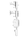
図1は本参考例の積層方法の工程図であり、図中上段側は平面工程図、下段側はそれに対応する側面工程図である。
本発明による参考例1に係る積層方法は、単結晶又は一方向凝固結晶の母材11に加熱源によって加熱されてなる溶融積層部12を積層形成する溶接方法において、所定間隙13を有して複数(本参考例では2本)の第1積層部12−1,第2積層部12−2を形成し、前記間隙13に第3積層部12−3を形成するようにしたものである。
第1積層部12−1と第2積層部12−2との間隙13に第3積層部12−3を積層させているので、単結晶を健全に形成することができる。
[Reference Example 1]
FIG. 1 is a process diagram of the laminating method of this reference example, in which the upper side is a plane process diagram and the lower side is a corresponding side process diagram.
The laminating method according to Reference Example 1 according to the present invention is a welding method for laminating and forming a molten laminated
Since the third stacked unit 12-3 is stacked in the
すなわち、第1積層部12−1に対して間隙13をもって第2積層部12−2を形成するので、第1積層部12−1の熱影響を受けることなく、第2積層部12−2を形成することができる。そして、この間隙13を形成する第1積層部12−1と第2積層部12−2とが左右対称な温度条件を確保するので、間隙13に形成される第3積層部12−3の結晶成長に異結晶が積層することがなくなる。
That is, since the second stacked portion 12-2 is formed with a
加熱源としては、例えばレーザビーム、電子ビーム、プラズマ加熱等で局所的に加熱できるような公知の加熱源を用いればいずれであってもよい。図1の実施例ではレーザビーム14を用いて溶接部を形成している。
また、溶化材については、金属、高分子材料、セラミックス等であり、その供給方法としては、特に限定されるものではなく、例えばワイヤ供給、パウダ供給、パウダ敷設等いずれのものでもよい。
As the heating source, any known heating source that can be locally heated by, for example, a laser beam, an electron beam, plasma heating or the like may be used. In the embodiment of FIG. 1, a
Further, the solubilizing material is a metal, a polymer material, ceramics, and the like, and the supply method is not particularly limited. For example, any of wire supply, powder supply, powder laying, and the like may be used.
図1の参考例では溶化材の供給を粉末状の溶化材15Aで供給する方法を示しており、図2の参考例では置き粉末(または置きワイヤ)の溶化材15Bについて示している。
The reference example of FIG. 1 shows a method of supplying the solubilizing material with the powdered solubilizing
本参考例では、例えば2mmの円形のYAGレーザビーム(走査速度:5mm/秒)14とし、このレーザビーム14により初期温度20℃の条件で、単位面積当りの入熱量500W/mm2 で加熱し、溶化材(粒径:50μm)15を2g/分で供給しつつ積層体(幅2mm)を母材11の表面に形成した。
In this reference example, for example, a 2 mm circular YAG laser beam (scanning speed: 5 mm / second) 14 is used, and the
また、図3に示すように、第1積層部12−1と第2積層部12−2との距離Lは、間隙13に形成する第3積層部12−3の断面積が第1積層部12−1の断面積と同じとなるようにすればよい。
これにより、第1乃至第3積層部で形成する積層体16の表面が略平坦面となるので、好ましい。なお、この積層体16には後述するように、さらに積層体を何層も積層させて柱状積層部を形成することもできる。
Further, as shown in FIG. 3, the distance L between the first stacked unit 12-1 and the second stacked unit 12-2 is that the cross-sectional area of the third stacked unit 12-3 formed in the
Thereby, the surface of the
図4は本実施例の積層方法にかかる側面図である。なお、参考例1の構成部材と同一の部材については同一の符号を付してその説明は省略する。
本発明による実施例1に係る積層方法は、単結晶又は一方向凝固結晶の母材11に加熱源によって加熱されてなる溶融積層部12を積層形成する溶接方法において、所定間隙13を有して複数(本実施例では5本)の第1積層部12−1、第2積層部12−2、第3積層部12−3、第4積層部12−4、第5積層部12−5を形成し、これらの間隙13−1,13−2,13−3,13−4に第6積層部12−6乃至第9積層部12−9を形成するようにしたものである。これにより、第1積層体16−1を形成している。次いで、第1積層体16−1の上に、第10積層部12−10、第11積層部12−11、第12積層部12−12、第13積層部12−13、第14積層部12−14を形成し、これらの間隙13−5乃至13−8に第15積層部12−15乃至第18積層部12−18を形成するようにしたものである。これにより、第2積層体16−2を形成している。これにより、この間隙を形成する間隙両側の積層部が左右対称な温度条件を確保するので、間隙に形成される積層部の結晶成長に異結晶が積層することなく、良好な第1積層体16−1を形成することができ、該第1積層体16−1の上に同様にして積層部を形成することで、良好な第2積層体16−2を形成することができる。
図20にこの積層体の一部分の顕微鏡写真を示す。図20では、第6積層体12−6、第2積層体及び第7積層体12−7の上に第11積層体12−11が形成されている様子を示す。この図面に示すように、本実施例によれば、異結晶のない良好な積層体を形成できることが実証された。
FIG. 4 is a side view according to the lamination method of the present embodiment. In addition, about the member same as the structural member of the reference example 1, the same code | symbol is attached | subjected and the description is abbreviate | omitted.
The laminating method according to the first embodiment of the present invention is a welding method for laminating and forming a molten laminated
FIG. 20 shows a micrograph of a part of this laminate. FIG. 20 illustrates a state in which an eleventh stacked body 12-11 is formed on the sixth stacked body 12-6, the second stacked body, and the seventh stacked body 12-7. As shown in this drawing, according to this example, it was demonstrated that a good laminate without different crystals can be formed.
図5は実施例1における変形例を示す。
図5に示すように、第2積層体16−1を形成する際に、第11積層部12−11と第12積層部12−12との間に、第16積層部12−16を形成するのではなく、第16積層部12−16を第12積層部12−12と第13積層部12−13の間に積層させるようにしている。この結果、第15積層部12−15を形成する際に熱影響を受けた第11積層部の隣り側に位置する第12積層部12−12と第13積層部12−13の間隙13−6に第16積層部12−16を形成することとなり、熱影響がなく組織制御することができ、異結晶の発生がない良好な肉盛りが可能となる。
FIG. 5 shows a modification of the first embodiment.
As shown in FIG. 5, when the second stacked body 16-1 is formed, the sixteenth stacked section 12-16 is formed between the eleventh stacked section 12-11 and the twelfth stacked section 12-12. Instead, the sixteenth laminated portion 12-16 is laminated between the twelfth laminated portion 12-12 and the thirteenth laminated portion 12-13. As a result, the gap 13-6 between the twelfth stacked portion 12-12 and the thirteenth stacked portion 12-13 located on the side adjacent to the eleventh stacked portion affected by heat when forming the fifteenth stacked portion 12-15. Thus, the sixteenth laminated portion 12-16 is formed, the structure can be controlled without being affected by heat, and a good build-up without the occurrence of different crystals can be achieved.
図6は本実施例の積層方法にかかる側面図である。なお、参考例1の構成部材と同一の部材については同一の符号を付してその説明は省略する。
本発明による実施例2に係る積層方法は、母材11に欠陥部21が発生している場合に、該欠陥部21を除去し、さらに該除去部に積層部を形成して欠陥を補修するようにしたものである。
FIG. 6 is a side view according to the lamination method of the present embodiment. In addition, about the member same as the structural member of the reference example 1, the same code | symbol is attached | subjected and the description is abbreviate | omitted.
In the laminating method according to the second embodiment of the present invention, when a
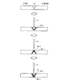
図6に示すように、先ず、母材11の欠陥部21を含む部分を除去し、凹部22を形成する。この際、該凹部22の開先加工部の対向面をテーパ状とし第1テーパ部23−1、第2テーパ部23−2としている。
次いで、参考例1と同様な方法により、所定間隙13を有して複数(本実施例では3本)の第1積層部12−1、第2積層部12−2、第3積層部12−3を形成し、これらの間隙13−1,13−2及び第1積層部12−1と第1テーパ部23−1との第3間隙113−3、第3積層部12−3と第2テーパ部23−2との第3間隙13−4に第4積層部12−4乃至第7積層部12−7を形成するようにしたものである。これにより、欠陥部21を含む部分を削除して形成した凹部22内に積層体16を形成し、補修を完了している。
このテーパ部の角度は特に限定されるものではないが、例えば60°±20°とすればよい。このテーパ部により形成される間隙13−3、13−4が第1積層部の斜面と同様な角度となるので、熱影響が緩和され、異結晶の発生がない補修をすることが可能となる。
As shown in FIG. 6, first, the portion including the
Next, in the same manner as in Reference Example 1, a plurality of (three in the present example) first laminated portion 12-1, second laminated portion 12-2, and third laminated portion 12- having a
The angle of the taper portion is not particularly limited, but may be 60 ° ± 20 °, for example. Since the gaps 13-3 and 13-4 formed by the taper portion have the same angle as the inclined surface of the first laminated portion, the thermal effect is mitigated, and it is possible to perform repair without generation of different crystals. .
これにより、熱影響がなく組織制御することができ、異結晶の発生がない良好な欠陥部21の削除に伴う補修が可能となる。
As a result, the structure can be controlled without being affected by heat, and the repair accompanying the deletion of the
なお、上述した凹部22の形成及びテーパ部23−1,23−2の形成に際しては、積層部が左右対称になるよう積層されるに設定する。よって、常に奇数の積層部が形成されることが好ましい。これは、複数の積層部となると左右の熱バランスが崩れることとなるからである。 In forming the concave portion 22 and the tapered portions 23-1 and 23-2 described above, the laminated portions are set so as to be symmetrical. Therefore, it is preferable that an odd number of stacked portions are always formed. This is because the thermal balance between the left and right sides is lost when a plurality of stacked portions are formed.
図7は本実施例の積層方法にかかる側面図である。なお、参考例1の構成部材と同一の部材については同一の符号を付してその説明は省略する。
本発明による実施例3に係る積層方法は、母材11に他の接合材31を接合するようにしたものである。
FIG. 7 is a side view according to the lamination method of the present embodiment. In addition, about the member same as the structural member of the reference example 1, the same code | symbol is attached | subjected and the description is abbreviate | omitted.
In the lamination method according to the third embodiment of the present invention, another
図7に示すように、先ず、母材11と接合する接合材31に開先加工を施し、凹部32を形成する。この際、該凹部32の開先加工部の対向面をテーパ状とし第1テーパ部33−1、第2テーパ部33−2としている。
次に、凹部底面部分を加熱して溶融接合35を行う。この溶融接合については、後述する。
As shown in FIG. 7, first, groove processing is performed on the
Next, the bottom surface of the recess is heated to perform
次いで、第1テーパ部33−1と第2テーパ部33との間に、第1積層部12−1を形成し、第1間隙13−1及び第2間隙13−2を形成する。次いで、第1間隙13−1に第2積層部12−2及び第2間隙13−2に第3積層部12−3を形成し、第1積層部12−1乃至第3積層部12−3から第1積層体16−1を形成するようにしたものである。これにより、接合部の凹部を底面から埋めていき、凹部32内に第4積層体16−1を順次形成して接合材31との接合を完了するようにしている。
Next, the first stacked portion 12-1 is formed between the first tapered portion 33-1 and the second tapered portion 33, and the first gap 13-1 and the second gap 13-2 are formed. Next, the second stacked portion 12-2 is formed in the first gap 13-1, and the third stacked portion 12-3 is formed in the second gap 13-2, and the first stacked portion 12-1 to the third stacked portion 12-3 are formed. The first laminated body 16-1 is formed. Thereby, the concave portion of the joint portion is filled from the bottom surface, and the fourth laminated body 16-1 is sequentially formed in the
これにより、熱影響がなく組織制御することができ、異結晶の発生がない良好な接合が可能となる。 As a result, the structure can be controlled without being affected by heat, and good bonding without occurrence of different crystals can be achieved.
図8の接合は実施例3の変形例を示すものであり、母材の厚みが薄い場合、母材と同じ組織及び結晶方位を有するあて金36をあてて接合する場合である。
8 shows a modification of the third embodiment. In the case where the thickness of the base material is small, the joining is performed by applying an
先ず、母材11と接合材31とをつき合わせ、開先加工を施し、第1テーパ部31−1及び第2テーパ部31−2を形成する。
次に、あて金36を裏面側にあてて、凹部32を形成する。
First, the
Next, the
その後、上述したのと同様に凹部32内に積層部を形成し、複数の積層体を形成し、凹部32を埋め、両者の接合を完了するようにしている。
After that, as described above, a stacked portion is formed in the
図9は本実施例の積層方法にかかる三面図である。なお、参考例1の構成部材と同一の部材については同一の符号を付してその説明は省略する。
本発明による実施例4に係る積層方法は、母材11を複数の結晶方位の異なるものから構成されてなる母材に溶接を施す場合に割れが発生しないように接合材31を接合するようにしたものである。例えば母材に強度特性に応じて高温での高強度化を図るために、母材の結晶方向が異ならせるようにさせる場合がある。
FIG. 9 is a three-side view according to the lamination method of the present embodiment. In addition, about the member same as the structural member of the reference example 1, the same code | symbol is attached | subjected and the description is abbreviate | omitted.
In the laminating method according to the fourth embodiment of the present invention, when the
本実施例では、図9に示すように、母材として五種類の結晶方位の異なる母材11−1〜11−5とした場合、該母材の結晶成長方向に直交する方向に間隙13をもって第1積層部12−1及び第2積層部12−2を形成する。
次いで、間隙に第3積層部12−3を積層させ、積層体16を形成させている。
この際、母材表面に形成された積層部の結晶方位が、下側の母材の結晶成長方向の方位同じように結晶成長がなされる。この結果、母材同士の結晶粒界に沿って積層体を形成したような場合に生ずる割れが発生することがなくなる。なお、図9においては、母材とその上に積層される積層部12−2の結晶方位が同じことを同じ模様を付すことでその概念を示している。
In this example, as shown in FIG. 9, when five base materials 11-1 to 11-5 having different crystal orientations are used as the base material, there is a
Next, the third stacked portion 12-3 is stacked in the gap to form the stacked
At this time, the crystal growth is performed in the same manner as the crystal orientation of the stacked portion formed on the surface of the base material in the crystal growth direction of the lower base material. As a result, there is no occurrence of cracking that occurs when a laminate is formed along the crystal grain boundaries between the base materials. In addition, in FIG. 9, the concept is shown by attaching | subjecting the same pattern that the crystal orientation of the base material and the laminated part 12-2 laminated | stacked on it is the same.
図10は本実施例にかかる工程概略図である。
本実施例では、溶接施工前において、母材の融点以下の条件で母材を熱処理することにより、単結晶又は一方向性凝固結晶の組織を保持したまま析出物或いはミクロ偏析を解消又は緩和させるようにしたものである。
FIG. 10 is a process schematic diagram according to this example.
In this example, before welding, the base material is heat-treated under conditions below the melting point of the base material, thereby eliminating or mitigating precipitates or microsegregation while maintaining the structure of the single crystal or unidirectionally solidified crystal. It is what I did.
ここで、通常の溶接における溶体化処理とは、例えば金属の固体と液体の共存領域に移行する温度である固相線温度よりも数10℃低い温度(特には30〜50℃程度低い温度とするのが好ましい。)で数時間の熱処理を施し、一般に強度向上を図ることを目的とした熱処理のことをいう。 Here, the solution treatment in ordinary welding is, for example, a temperature that is several tens of degrees Centigrade lower than the solidus temperature that is a temperature at which the solid and liquid coexist with the liquid (for example, a temperature that is lower by about 30 to 50 ° C.). It is preferable that the heat treatment is performed for several hours and is generally intended to improve the strength.
一方、本発明における熱処理はこの溶体化処理の温度領域とは異なる高い温度領域で熱処理することをいう。具体的には、1)固相線温度と同程度の熱処理を行う場合、2)固相線温度と同等以上の温度で熱処理を行う場合、3)完全液体に移行する液相線温度以上で熱処理を行う場合をいう。 On the other hand, heat treatment in the present invention refers to heat treatment in a high temperature region different from the temperature region of the solution treatment. Specifically, 1) When a heat treatment similar to the solidus temperature is performed, 2) When a heat treatment is performed at a temperature equal to or higher than the solidus temperature, and 3) Above the liquidus temperature at which the liquid transitions to a complete liquid This refers to the case where heat treatment is performed.
よって、本発明では、母材に肉盛り溶接等の溶接を行うに際し、母材に対して2段階の熱処理を施すようにしている。すなわち、一般の溶体化処理による熱処理と、該溶体化処理よりも高温側で行う高温熱処理により溶接前の熱処理を施すようにしている。 Therefore, in the present invention, when performing welding such as build-up welding on the base material, the base material is subjected to two stages of heat treatment. That is, the heat treatment before welding is performed by a heat treatment by a general solution treatment and a high-temperature heat treatment performed on a higher temperature side than the solution treatment.
具体的には、図10に示すように、母材11に対し、先ず、第1加熱炉61において第1の熱処理工程62として、通常の溶体化処理を施し、次に、第2加熱炉63において第2の熱処理工程64として、上述した1)〜3)のいずれかの高温熱処理を施すようにしている。
その後、溶接工程65において例えばレーザビーム14により肉盛り溶接を行い、母材11の表面に溶接部12を形成する。なお、図10中、18は粉末状の溶化材15Aを供給する供給管を図示する。
Specifically, as shown in FIG. 10, the
Thereafter, in the welding process 65, for example, build-up welding is performed by the
この熱処理により、析出物或いはミクロ偏析を解消又は緩和させ、その後の溶接におけるミクロ偏析に起因するような別の結晶の成長をなくすことができる。 By this heat treatment, precipitates or microsegregation can be eliminated or alleviated, and the growth of other crystals caused by microsegregation in the subsequent welding can be eliminated.
本実施例では、例えばニッケル合金(CM247LC(商品名:キャノンマスケゴン社製)、固相線温度:1280℃、液相線温度:1370℃)を用いて一方向凝固母材を鋳造し、その後、第1熱処理工程62において、1260℃で3時間の溶体化処理を施した。その後、第2熱処理工程64において、表面単位面積あたりの入熱量を1.5×10⁶J/m2におさえて析出物及びミクロ偏析をなくした。 In this example, a unidirectional solidified base material is cast using, for example, a nickel alloy (CM247LC (trade name: manufactured by Canon Maskegon), solidus temperature: 1280 ° C., liquidus temperature: 1370 ° C.), and then In the first heat treatment step 62, solution treatment was performed at 1260 ° C. for 3 hours. Thereafter, in the second heat treatment step 64, the amount of heat input per unit surface area was suppressed to 1.5 × 10 6 J / m 2 to eliminate precipitates and microsegregation.
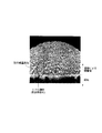
図22は母材11に対し、第1熱処理及び第2熱処理を施し、その後、積層部12を複数層形成させて肉盛り部を形成した場合の顕微鏡図である。図22に示すように、第1熱処理である溶体化理と高温の第2熱処理を施すことにより、溶接における別の結晶の発生がなくなる。
FIG. 22 is a microscopic view in the case where the
これに対し、図23に示すように、第1熱処理しかしない場合には、母材11中にミクロ偏析が生じ、別の結晶の発生が見られた。
On the other hand, as shown in FIG. 23, when only the first heat treatment was performed, microsegregation occurred in the
本実施例では、溶接部12を1本の線状体としたが、上述した実施例1乃至5における複数本の溶接においても、この前処理を適用することで、ミクロ偏析を解消し、別の結晶の発生を防止することができる。
In the present embodiment, the welded
また、図11に示すように、置きワイヤ状の溶化材15Bを用いるようにしてもよい。
Moreover, as shown in FIG. 11, you may make it use the standing wire-shaped
また、図12に示すように、積層部を線状体とすることなく、スポット形状の積層部12aとするようにしてもよい。
また、穴埋め作業も同様に行うことができる。
Further, as shown in FIG. 12, the laminated portion may be a spot-shaped
Further, the hole filling operation can be performed in the same manner.
また、本前処理は、等軸晶材に適用することもできる。 This pretreatment can also be applied to equiaxed crystals.
図13は本実施例にかかる工程概略図である。なお、実施例5の構成部材と同一の部材については同一の符号を付してその説明は省略する。
図10乃至図12の実施例においては、加熱炉により母材の全体を第2熱処理により行っているが、本発明はこれに限定されるものではない。例えば加熱炉61による第1熱処理工程61を行った後、第2熱処理工程64をレーザビーム14により行い、局所的に熱処理するようにして、析出物或いは偏析除去(緩和)領域66を形成するようにしてもよい。
FIG. 13 is a process schematic diagram according to this example. In addition, about the member same as the structural member of Example 5, the same code | symbol is attached | subjected and the description is abbreviate | omitted.
10 to 12, the entire base material is subjected to the second heat treatment by the heating furnace, but the present invention is not limited to this. For example, after the first
また、図14に示すように、置きワイヤ状の溶化材15Bを用いるようにしてもよい。
Moreover, as shown in FIG. 14, you may make it use the standing wire-
また、図15に示すように、積層部を線状体とすることなく、スポット形状の積層部12aとするようにしてもよい。この際にはレーザビームでの第2熱処理工程64もスポット処理で足りることとなる。
Moreover, as shown in FIG. 15, you may make it make it the spot-shaped
図16は本実施例にかかる工程概略図である。なお、実施例5の構成部材と同一の部材については同一の符号を付してその説明は省略する。
本実施例では、母材に欠陥部がある場合、この欠陥部71を除去してその除去部に補修を施す場合において、補修を行う前に熱処理を施すものである。
図16に示すように、母材11の欠陥部71を除去し、凹部72を形成する。その後、加熱炉73により熱処理工程74を施して、ミクロ偏析を解消させている。
その後、通常の溶接処理により、積層部12を形成し、補修工程75を行っている。
図17は、欠陥部の補修に際し、熱処理工程を実施例6と同様にレーザビーム14を用いた場合である。
FIG. 16 is a process schematic diagram according to this example. In addition, about the member same as the structural member of Example 5, the same code | symbol is attached | subjected and the description is abbreviate | omitted.
In this embodiment, when there is a defective portion in the base material, when the
As shown in FIG. 16, the
Thereafter, the
FIG. 17 shows a case where a
図18は本実施例の工程図である。なお、実施例5の構成部材と同一の部材については同一の符号を付してその説明は省略する。
本発明による実施例8に係る前処理方法は、母材11に他の接合材31を接合する場合に適用するものである。
FIG. 18 is a process diagram of this example. In addition, about the member same as the structural member of Example 5, the same code | symbol is attached | subjected and the description is abbreviate | omitted.
The pretreatment method according to the eighth embodiment of the present invention is applied when another
図18に示すように、先ず、母材11に接合する接合材31に開先加工を施し、テーパ状の凹部81を形成する。この際、該凹部81の所定厚さ、第2熱処理を施し、第1析出物或いは偏析除去領域66−1を形成する。その後、裏返しにし、裏面側から母材11と接合材31との接合付近に対して第2熱処理を施し、第2析出物或いは偏析除去領域66−2を形成する。
その後、再度裏返し、凹部81に積層部82を施した。
As shown in FIG. 18, first, groove processing is performed on the
Then, it turned over again and the
これにより、母材と接合材とを溶接するに際し、ミクロ偏析を解消し、異なる結晶の発生を防止した補修が可能となる。 As a result, when the base material and the bonding material are welded, the microsegregation is eliminated, and repair that prevents the generation of different crystals is possible.
図19の接合は、実施例8の変形例を示すものであり、母材の厚みが薄い場合、母材と同じ組織及び結晶方位を有するあて金36をあてて接合する場合である。
The joining shown in FIG. 19 shows a modification of the eighth embodiment. In this case, when the thickness of the base material is small, the joining is performed by applying an
先ず、母材11と接合材31とをつき合わせ、開先加工を施し、凹部81を形成する。
次に、あて金36を裏面側にあてる。
次に、該凹部81及びあて金36に、第2熱処理を施し、析出物或いは偏析除去領域66を形成する。その後、凹部81に積層部82を施し、その後、あて金36を除去した。
First, the
Next, the
Next, a second heat treatment is performed on the
これにより、母材と接合材とを溶接するに際し、ミクロ偏析を解消し、異なる結晶の発生を防止した補修が可能となる。 As a result, when the base material and the bonding material are welded, the microsegregation is eliminated, and repair that prevents the generation of different crystals is possible.
その後、上述したのと同様に凹部32内に積層部を形成し、複数の積層体を形成し、凹部32を埋め、両者の接合を完了するようにしている。
After that, as described above, a stacked portion is formed in the
以上のように、本発明にかかる溶接方法は、単結晶及び一方向凝固の母材に積層部を形成するに際し、積層方法を規定することで健全な積層が可能となり、タービンの動翼、静翼等の肉盛り溶接、補修、接合等に用いて適している。 As described above, the welding method according to the present invention enables sound lamination by defining a lamination method when forming a laminated portion on a single crystal and a unidirectionally solidified base material. Suitable for overlay welding of wings, repair, joining, etc.
11 母材
12−1〜12−16 積層部
13−1〜13−8 間隙
14 レーザビーム
15A、15B 溶化材
16 積層体
DESCRIPTION OF
Claims (11)
所定間隙を有して積層部を複数形成し、
前記間隙に積層部を形成して第1層積層体を形成し、
該第1層積層体に対して積層部が複数形成され、複数の積層部どうしが所定間隙を有し、
前記間隙に積層部を形成して第2層積層体を形成することを特徴とする溶接方法。 In a welding method for forming a melt-laminated portion in a base material of a single crystal or unidirectionally solidified crystal,
Forming a plurality of laminated portions with a predetermined gap;
Forming a laminated portion in the gap to form a first layer laminate;
Product layer portion with respect to said first layer laminate is formed with a plurality, the plurality of laminated portions each other is have a predetermined gap,
A welding method, wherein a second layer laminate is formed by forming a laminate in the gap.
第3層積層体以降を第2層積層体と同様に繰り返し、複数層の積層体を形成することを特徴とする溶接方法。 In claim 1,
A welding method characterized in that the third layer and subsequent layers are repeated in the same manner as the second layer stacked body to form a multi-layered stacked body.
前記間隙に積層部を形成するに際し、
積層部を形成した間隙の両隣の間隙以外の間隙に積層部を形成することを特徴とする溶接方法。 In claim 1 or 2,
When forming the laminated portion in the gap,
A welding method comprising forming a laminated portion in a gap other than a gap adjacent to both sides of the gap in which the laminated portion is formed.
加熱源により、ワイヤ供給、パウダ供給、パウダ敷設のいずれかの方法により溶化材を溶かして、前記積層部を形成することを特徴とする溶接方法。 In any one of Claims 1 thru | or 3,
A welding method characterized in that the laminated portion is formed by melting a melted material by any one of wire supply, powder supply, and powder laying with a heating source.
前記母材が一方向凝固結晶構造である場合に、
前記母材の結晶成長方向と直交する方向に、加熱源により、ワイヤ供給、パウダ供給、パウダ敷設のいずれかの方法により溶化材を溶かして、前記積層部を形成することを特徴とする溶接方法。 In any one of Claims 1 thru | or 4,
When the base material has a unidirectionally solidified crystal structure,
A welding method characterized in that the layered portion is formed by melting the melted material in a direction orthogonal to the crystal growth direction of the base material by any one of wire supply, powder supply, and powder laying by a heating source. .
前記母材が鋳造物であり、
該鋳造物の欠陥部分を削除して凹部を形成し、
該凹部に積層体を形成することを特徴とする鋳造品の補修方法。 Using the welding method according to any one of claims 1 to 5,
The base material is a casting,
Delete the defective part of the casting to form a recess,
A method for repairing a cast product, comprising forming a laminate in the recess.
前記凹部の対向面がテーパ状であることを特徴とする鋳造品の補修方法。 In claim 6,
A method for repairing a cast product, wherein the opposing surface of the recess is tapered.
前記母材に接合材を接合するに際し、
前記母材と接合材とに開先加工を施し、
該開先部に積層体を形成することを特徴とする接合材の接合方法。 Using the welding method according to any one of claims 1 to 5,
When joining a bonding material to the base material,
Applying groove processing to the base material and the bonding material,
A method for joining a joining material, comprising forming a laminate on the groove portion.
該開先加工部の対向面がテーパ状であることを特徴とする接合材の接合方法。 In claim 8,
The bonding method of the bonding material, wherein the facing surface of the groove processing portion is tapered.
前記溶接の前処理工程が、
前記母材の固相線温度よりも30〜50℃低い温度で溶体化処理を行う第1の熱処理工程と、
前記第1の熱処理温度よりも高い温度で熱処理を行い、析出物或いはミクロ偏析を解消させる第2の熱処理工程とを有することを特徴とする溶接方法。 In any one of Claims 1 thru | or 5,
The welding pretreatment step
A first heat treatment step for performing a solution treatment at a temperature lower by 30 to 50 ° C. than a solidus temperature of the base material;
And a second heat treatment step of performing heat treatment at a temperature higher than the first heat treatment temperature to eliminate precipitates or microsegregation.
前記第2の熱処理工程が固相線温度と同等の温度、固相線温度よりも高い温度又は液相線温度のいずれかであることを特徴とする溶接方法。 In claim 10,
The welding method, wherein the second heat treatment step is a temperature equal to the solidus temperature, a temperature higher than the solidus temperature, or a liquidus temperature.
Priority Applications (6)
| Application Number | Priority Date | Filing Date | Title |
|---|---|---|---|
| JP2003392694A JP4551082B2 (en) | 2003-11-21 | 2003-11-21 | Welding method |
| US10/935,074 US7568609B2 (en) | 2003-11-21 | 2004-09-08 | Welding method |
| CNB2004100882164A CN1326654C (en) | 2003-11-21 | 2004-10-21 | Welding method |
| EP09170131A EP2123803B1 (en) | 2003-11-21 | 2004-10-26 | Welding method |
| EP04025439A EP1541723B1 (en) | 2003-11-21 | 2004-10-26 | Welding method |
| RU2004133863/02A RU2284251C2 (en) | 2003-11-21 | 2004-11-19 | Welding method |
Applications Claiming Priority (1)
| Application Number | Priority Date | Filing Date | Title |
|---|---|---|---|
| JP2003392694A JP4551082B2 (en) | 2003-11-21 | 2003-11-21 | Welding method |
Publications (2)
| Publication Number | Publication Date |
|---|---|
| JP2005152918A JP2005152918A (en) | 2005-06-16 |
| JP4551082B2 true JP4551082B2 (en) | 2010-09-22 |
Family
ID=34510431
Family Applications (1)
| Application Number | Title | Priority Date | Filing Date |
|---|---|---|---|
| JP2003392694A Expired - Lifetime JP4551082B2 (en) | 2003-11-21 | 2003-11-21 | Welding method |
Country Status (5)
| Country | Link |
|---|---|
| US (1) | US7568609B2 (en) |
| EP (2) | EP1541723B1 (en) |
| JP (1) | JP4551082B2 (en) |
| CN (1) | CN1326654C (en) |
| RU (1) | RU2284251C2 (en) |
Cited By (1)
| Publication number | Priority date | Publication date | Assignee | Title |
|---|---|---|---|---|
| WO2020079816A1 (en) | 2018-10-18 | 2020-04-23 | 三菱電機株式会社 | Method for additive fabrication, and method for generating processing route |
Families Citing this family (44)
| Publication number | Priority date | Publication date | Assignee | Title |
|---|---|---|---|---|
| EP1561839A1 (en) * | 2004-01-27 | 2005-08-10 | Siemens Aktiengesellschaft | Process of manufacturing a layered structure comprising a columnar ceramic layer |
| GB0420578D0 (en) * | 2004-09-16 | 2004-10-20 | Rolls Royce Plc | Forming structures by laser deposition |
| EP1772228A1 (en) * | 2005-10-07 | 2007-04-11 | Siemens Aktiengesellschaft | Process for repairing a workpiece with an oriented microstructure |
| JP4928916B2 (en) * | 2006-11-22 | 2012-05-09 | 株式会社東芝 | Gas turbine high temperature part repair method and gas turbine high temperature part |
| CN101357429B (en) * | 2007-08-03 | 2010-05-19 | 上海船厂船舶有限公司 | Welding repair method of iron casting |
| JP4818297B2 (en) * | 2008-03-19 | 2011-11-16 | 株式会社東芝 | Gas turbine component repair method and gas turbine component |
| DE102008016170A1 (en) * | 2008-03-28 | 2009-10-01 | Fraunhofer-Gesellschaft zur Förderung der angewandten Forschung e.V. | Component with overlapping welds and a method of manufacture |
| WO2009143909A1 (en) * | 2008-05-29 | 2009-12-03 | Siemens Aktiengesellschaft | Method and device for welding workpieces made of high-temperature resistant super alloys |
| FR2931714B1 (en) * | 2008-05-30 | 2010-06-25 | Snecma | CONSTRUCTION OF A PART OF A METAL PIECE BY THE MIG PROCESS WITH CURRENT AND PULSED WIRE |
| DE102009010025B4 (en) * | 2009-02-21 | 2011-06-22 | MTU Aero Engines GmbH, 80995 | A method of manufacturing an integrally bladed rotor |
| DE102009016260A1 (en) | 2009-04-03 | 2010-10-07 | Fraunhofer-Gesellschaft zur Förderung der angewandten Forschung e.V. | Method of welding and component |
| US8573949B2 (en) * | 2009-09-30 | 2013-11-05 | General Electric Company | Method and system for focused energy brazing |
| EP2322313A1 (en) * | 2009-11-13 | 2011-05-18 | Siemens Aktiengesellschaft | Method for welding workpieces from extremely heat-proof superalloys with particular feeding rate of the welding filler material |
| US8616852B2 (en) * | 2009-11-25 | 2013-12-31 | United Technologies Corporation | Welding repair method of an integrally bladed rotor |
| JP2011212730A (en) * | 2010-04-01 | 2011-10-27 | Hitachi Ltd | Metal deposition method, and laser metal deposition apparatus |
| US9168613B2 (en) | 2010-10-22 | 2015-10-27 | Paul T. Colby | Vertical laser cladding system |
| CH705327A1 (en) * | 2011-07-19 | 2013-01-31 | Alstom Technology Ltd | Lot for high-temperature soldering and method of repairing or manufacturing components using this solder. |
| CH705321A1 (en) | 2011-07-19 | 2013-01-31 | Alstom Technology Ltd | Solder foil for high-temperature soldering and method of repairing or manufacturing components using this solder film. |
| US9126287B2 (en) * | 2012-03-12 | 2015-09-08 | Siemens Energy, Inc. | Advanced pass progression for build-up welding |
| US9186757B2 (en) * | 2012-05-09 | 2015-11-17 | Siemens Energy, Inc. | Method of providing a turbine blade tip repair |
| US10415390B2 (en) | 2012-05-11 | 2019-09-17 | Siemens Energy, Inc. | Repair of directionally solidified alloys |
| JP5984578B2 (en) * | 2012-08-22 | 2016-09-06 | 三菱日立パワーシステムズ株式会社 | Bearing lining method |
| JP6071760B2 (en) * | 2013-05-31 | 2017-02-01 | 三菱重工業株式会社 | Turbine blade and method for manufacturing the same |
| ITMI20131271A1 (en) * | 2013-07-29 | 2015-01-30 | D G Weld S R L | METHOD FOR COATING IN METALLIC MATERIAL OF SPHEREIDAL CAST IRON BODIES AND MOLD FLOORS FOR DIE-CASTING MACHINES MADE OF THIS METHOD |
| EP3062953B1 (en) * | 2013-10-30 | 2023-05-17 | Raytheon Technologies Corporation | Laser powder deposition weld rework for gas turbine engine non-fusion weldable nickel castings |
| JP6235708B2 (en) * | 2013-10-30 | 2017-11-22 | ユナイテッド テクノロジーズ コーポレイションUnited Technologies Corporation | Welding repair by laser powder welding for gas turbine engine non-fusible nickel castings |
| JP6114718B2 (en) | 2014-06-17 | 2017-04-12 | 川崎重工業株式会社 | Axisymmetric body and method of manufacturing axisymmetric product |
| AR102454A1 (en) * | 2014-10-29 | 2017-03-01 | Ulterra Drilling Tech Lp | METHOD OF REPAIR OF SUBSTRATES OF CUTTING PIECES OF POLYCRYSTAL DIAMOND, CUTTING PIECE AND DRILL FOR UNDERGROUND DRILLING |
| US10247002B2 (en) | 2016-02-03 | 2019-04-02 | General Electric Company | In situ gas turbine prevention of crack growth progression |
| JP6887755B2 (en) * | 2016-02-16 | 2021-06-16 | 株式会社神戸製鋼所 | Stacking control device, stacking control method and program |
| SG10201700339YA (en) * | 2016-02-29 | 2017-09-28 | Rolls Royce Corp | Directed energy deposition for processing gas turbine engine components |
| JP6845686B2 (en) | 2016-12-27 | 2021-03-24 | 川崎重工業株式会社 | Protrusion formation method |
| US10807179B2 (en) * | 2017-02-17 | 2020-10-20 | General Electric Company | Method of build-up welding |
| US20180372428A1 (en) * | 2017-06-23 | 2018-12-27 | General Electric Company | Component including surface-modified article and method of modifying an article |
| JP2019084571A (en) * | 2017-11-08 | 2019-06-06 | 三菱重工業株式会社 | Built-up welding device |
| JP6892371B2 (en) * | 2017-11-14 | 2021-06-23 | 株式会社神戸製鋼所 | Manufacturing method and manufacturing equipment for laminated models |
| JP7067134B2 (en) * | 2018-03-07 | 2022-05-16 | 株式会社ジェイテクト | Modeling method of laminated modeling device and laminated modeling device |
| JP7082541B2 (en) * | 2018-07-20 | 2022-06-08 | 三菱重工業株式会社 | Repair welding method |
| US20210323092A1 (en) * | 2018-10-19 | 2021-10-21 | Mitsubishi Electric Corporation | Additive manufacturing apparatus and additive manufacturing method |
| JP7270428B2 (en) * | 2019-03-19 | 2023-05-10 | 三菱重工業株式会社 | Directionally solidified material, turbine rotor blade and method for repairing unidirectionally solidified material |
| DE102019210295A1 (en) * | 2019-07-11 | 2021-01-14 | Fraunhofer-Gesellschaft zur Förderung der angewandten Forschung e.V. | Process for coating a surface of a substrate by laser deposition welding |
| DE102019210430A1 (en) * | 2019-07-15 | 2021-01-21 | Siemens Aktiengesellschaft | Electron beam welding of nickel base superalloys and fixture |
| JP7181163B2 (en) * | 2019-07-19 | 2022-11-30 | 株式会社神戸製鋼所 | Laminated structure manufacturing method |
| US20230131125A1 (en) * | 2020-04-23 | 2023-04-27 | Mitsubishi Electric Corporation | Additive manufacturing apparatus, additive manufacturing method, and machine learning device |
Citations (7)
| Publication number | Priority date | Publication date | Assignee | Title |
|---|---|---|---|---|
| JPH0775893A (en) * | 1993-09-03 | 1995-03-20 | Hitachi Ltd | Method for repairing structure and preventive maintenance method |
| JPH11335802A (en) * | 1998-05-26 | 1999-12-07 | Toshiba Corp | Treatment for recovering deterioration and damage in material of gas turbine parts, and gas turbine parts subjected to the treatment |
| JP2000210789A (en) * | 1999-01-27 | 2000-08-02 | Hitachi Ltd | Welding wire and repair method |
| JP2001269784A (en) * | 2000-03-28 | 2001-10-02 | Toshiba Corp | REPAIRING METHOD FOR GAS TURBINE BLADE MADE OF Ni-BASED SINGLE CRYSTAL SUPERALLOY AND DEVICE THEREFOR |
| JP2003048065A (en) * | 2001-05-15 | 2003-02-18 | United Technol Corp <Utc> | Repair of single crystal nickel based superalloy article |
| JP2003048053A (en) * | 2001-08-02 | 2003-02-18 | Mitsubishi Heavy Ind Ltd | Repairing method of oriented solidified crystal blade |
| JP2003524526A (en) * | 1999-12-10 | 2003-08-19 | ゼネラル・エレクトリック・カンパニイ | Welding repair of directional solidification products |
Family Cites Families (26)
| Publication number | Priority date | Publication date | Assignee | Title |
|---|---|---|---|---|
| US3610876A (en) * | 1969-12-22 | 1971-10-05 | Gopal Krishna Bhat | Variable parameter tungsten-inert gas welding |
| US3653432A (en) * | 1970-09-01 | 1972-04-04 | Us Army | Apparatus and method for unidirectionally solidifying high temperature material |
| US4605452A (en) * | 1981-12-14 | 1986-08-12 | United Technologies Corporation | Single crystal articles having controlled secondary crystallographic orientation |
| JPS62282796A (en) * | 1986-05-29 | 1987-12-08 | Mitsubishi Heavy Ind Ltd | Welding repair method for blade root part |
| JP2570710B2 (en) * | 1986-11-07 | 1997-01-16 | 石川島播磨重工業株式会社 | Method for improving residual stress in welds |
| US4940390A (en) | 1988-05-05 | 1990-07-10 | Westinghouse Electric Corp. | Turbine system having more failure resistant rotors and repair welding of low alloy ferrous turbine components by controlled weld build-up |
| US4903888A (en) * | 1988-05-05 | 1990-02-27 | Westinghouse Electric Corp. | Turbine system having more failure resistant rotors and repair welding of low alloy ferrous turbine components by controlled weld build-up |
| US5151249A (en) * | 1989-12-29 | 1992-09-29 | General Electric Company | Nickel-based single crystal superalloy and method of making |
| US5140123A (en) * | 1990-05-25 | 1992-08-18 | Kusakabe Electric & Machinery Co., Ltd. | Continuous manufacturing method for a metal welded tube and a manufacturing apparatus therefor |
| US5106010A (en) * | 1990-09-28 | 1992-04-21 | Chromalloy Gas Turbine Corporation | Welding high-strength nickel base superalloys |
| US5071059A (en) | 1991-03-11 | 1991-12-10 | General Motors Corporation | Method for joining single crystal turbine blade halves |
| US5554837A (en) * | 1993-09-03 | 1996-09-10 | Chromalloy Gas Turbine Corporation | Interactive laser welding at elevated temperatures of superalloy articles |
| US5914059A (en) * | 1995-05-01 | 1999-06-22 | United Technologies Corporation | Method of repairing metallic articles by energy beam deposition with reduced power density |
| DE69529178T2 (en) * | 1995-09-13 | 2003-10-02 | Boehler Schmiedetechnik Ges.M.B.H. & Co. Kg, Kapfenberg | METHOD FOR PRODUCING A TITANIUM ALLOY TURBINE BLADE AND TITANIUM ALLOY TURBINE BLADE |
| US5735044A (en) * | 1995-12-12 | 1998-04-07 | General Electric Company | Laser shock peening for gas turbine engine weld repair |
| US6446701B1 (en) * | 1997-04-11 | 2002-09-10 | Niranjan Das | Apparatus for unidirectional solidification of compounds |
| JP3763089B2 (en) | 1998-09-30 | 2006-04-05 | バブコック日立株式会社 | Overlay welding method |
| US6191379B1 (en) | 1999-04-05 | 2001-02-20 | General Electric Company | Heat treatment for weld beads |
| US6308767B1 (en) * | 1999-12-21 | 2001-10-30 | General Electric Company | Liquid metal bath furnace and casting method |
| JP2001288554A (en) | 2000-03-31 | 2001-10-19 | Toshiba Corp | Repairing material, method for repairing heat resisting alloy member, and hot zone parts repaired by the method |
| US6730876B2 (en) * | 2001-05-29 | 2004-05-04 | U.S. Pipe And Foundry Company | Highly ductile reduced imperfection weld for ductile iron and method for producing same |
| DE10137776C1 (en) * | 2001-08-02 | 2003-04-17 | Fraunhofer Ges Forschung | Process for the production of wear-resistant surface layers |
| JP4490608B2 (en) | 2001-08-09 | 2010-06-30 | 株式会社東芝 | Repair method of structure |
| RU2196672C1 (en) | 2001-12-17 | 2003-01-20 | Федеральное государственное унитарное предприятие "Всероссийский научно-исследовательский институт авиационных материалов" | Method for making rotor of gas turbine engine |
| DE10235892A1 (en) * | 2002-08-06 | 2003-09-11 | Bosch Gmbh Robert | Method for welding boundary between two thermoplastic workpieces using laser beam, comprises heating one or both workpieces in area of weld to temperature below its melting point using supplementary heaters |
| JP4036091B2 (en) * | 2002-12-17 | 2008-01-23 | 株式会社日立製作所 | Nickel-base heat-resistant alloy and gas turbine blade |
-
2003
- 2003-11-21 JP JP2003392694A patent/JP4551082B2/en not_active Expired - Lifetime
-
2004
- 2004-09-08 US US10/935,074 patent/US7568609B2/en active Active
- 2004-10-21 CN CNB2004100882164A patent/CN1326654C/en active Active
- 2004-10-26 EP EP04025439A patent/EP1541723B1/en active Active
- 2004-10-26 EP EP09170131A patent/EP2123803B1/en active Active
- 2004-11-19 RU RU2004133863/02A patent/RU2284251C2/en active
Patent Citations (7)
| Publication number | Priority date | Publication date | Assignee | Title |
|---|---|---|---|---|
| JPH0775893A (en) * | 1993-09-03 | 1995-03-20 | Hitachi Ltd | Method for repairing structure and preventive maintenance method |
| JPH11335802A (en) * | 1998-05-26 | 1999-12-07 | Toshiba Corp | Treatment for recovering deterioration and damage in material of gas turbine parts, and gas turbine parts subjected to the treatment |
| JP2000210789A (en) * | 1999-01-27 | 2000-08-02 | Hitachi Ltd | Welding wire and repair method |
| JP2003524526A (en) * | 1999-12-10 | 2003-08-19 | ゼネラル・エレクトリック・カンパニイ | Welding repair of directional solidification products |
| JP2001269784A (en) * | 2000-03-28 | 2001-10-02 | Toshiba Corp | REPAIRING METHOD FOR GAS TURBINE BLADE MADE OF Ni-BASED SINGLE CRYSTAL SUPERALLOY AND DEVICE THEREFOR |
| JP2003048065A (en) * | 2001-05-15 | 2003-02-18 | United Technol Corp <Utc> | Repair of single crystal nickel based superalloy article |
| JP2003048053A (en) * | 2001-08-02 | 2003-02-18 | Mitsubishi Heavy Ind Ltd | Repairing method of oriented solidified crystal blade |
Cited By (3)
| Publication number | Priority date | Publication date | Assignee | Title |
|---|---|---|---|---|
| WO2020079816A1 (en) | 2018-10-18 | 2020-04-23 | 三菱電機株式会社 | Method for additive fabrication, and method for generating processing route |
| EP3666448A4 (en) * | 2018-10-18 | 2020-06-17 | Mitsubishi Electric Corporation | Method for additive fabrication, and method for generating processing route |
| US11325190B2 (en) | 2018-10-18 | 2022-05-10 | Mitsubishi Electric Corporation | Additive manufacturing method and machining-path generation method |
Also Published As
| Publication number | Publication date |
|---|---|
| JP2005152918A (en) | 2005-06-16 |
| RU2004133863A (en) | 2006-05-10 |
| CN1326654C (en) | 2007-07-18 |
| CN1618560A (en) | 2005-05-25 |
| US20050109818A1 (en) | 2005-05-26 |
| RU2284251C2 (en) | 2006-09-27 |
| EP1541723B1 (en) | 2012-04-25 |
| EP1541723A3 (en) | 2009-11-18 |
| US7568609B2 (en) | 2009-08-04 |
| EP2123803A2 (en) | 2009-11-25 |
| EP2123803A3 (en) | 2010-11-03 |
| EP2123803B1 (en) | 2012-04-25 |
| EP1541723A2 (en) | 2005-06-15 |
Similar Documents
| Publication | Publication Date | Title |
|---|---|---|
| JP4551082B2 (en) | Welding method | |
| JP4928916B2 (en) | Gas turbine high temperature part repair method and gas turbine high temperature part | |
| JP6086992B2 (en) | Superalloy cladding and fusion welding process | |
| EP2986406B1 (en) | Build platform, apparatus and method for additive manufacturing | |
| US7780059B2 (en) | Method of forming a component on a substrate | |
| US9186740B2 (en) | Projection resistance brazing of superalloys | |
| US9273562B2 (en) | Projection resistance welding of superalloys | |
| KR20170031238A (en) | Optimization of melt pool shape in a joining process | |
| US9186724B2 (en) | Electroslag and electrogas repair of superalloy components | |
| JP2011161459A (en) | Method of welding material with high-corrosion resistance | |
| KR20150054696A (en) | Method for utilizing a braze material with carbon structures | |
| KR20150041049A (en) | Stud welding repair of superalloy components | |
| CN105722635A (en) | Welding process and reduced restraint weld joint | |
| JP6727095B2 (en) | Dissimilar metal joining method | |
| US10478920B2 (en) | Dual wall components for gas turbine engines | |
| JP2008264841A (en) | Welding method | |
| KR20150088181A (en) | Method of cladding and fusion welding of superalloys using composite filler powder | |
| JP2017094382A (en) | Laser welding joint | |
| EP3668680B1 (en) | Laser metal deposition with cored filler wire |
Legal Events
| Date | Code | Title | Description |
|---|---|---|---|
| A621 | Written request for application examination |
Free format text: JAPANESE INTERMEDIATE CODE: A621 Effective date: 20060227 |
|
| A977 | Report on retrieval |
Free format text: JAPANESE INTERMEDIATE CODE: A971007 Effective date: 20080417 |
|
| A131 | Notification of reasons for refusal |
Free format text: JAPANESE INTERMEDIATE CODE: A131 Effective date: 20080422 |
|
| A521 | Request for written amendment filed |
Free format text: JAPANESE INTERMEDIATE CODE: A523 Effective date: 20080619 |
|
| A131 | Notification of reasons for refusal |
Free format text: JAPANESE INTERMEDIATE CODE: A131 Effective date: 20090804 |
|
| A521 | Request for written amendment filed |
Free format text: JAPANESE INTERMEDIATE CODE: A523 Effective date: 20091005 |
|
| A131 | Notification of reasons for refusal |
Free format text: JAPANESE INTERMEDIATE CODE: A131 Effective date: 20091104 |
|
| A521 | Request for written amendment filed |
Free format text: JAPANESE INTERMEDIATE CODE: A523 Effective date: 20091216 |
|
| TRDD | Decision of grant or rejection written | ||
| A01 | Written decision to grant a patent or to grant a registration (utility model) |
Free format text: JAPANESE INTERMEDIATE CODE: A01 Effective date: 20100615 |
|
| A01 | Written decision to grant a patent or to grant a registration (utility model) |
Free format text: JAPANESE INTERMEDIATE CODE: A01 |
|
| A61 | First payment of annual fees (during grant procedure) |
Free format text: JAPANESE INTERMEDIATE CODE: A61 Effective date: 20100709 |
|
| R151 | Written notification of patent or utility model registration |
Ref document number: 4551082 Country of ref document: JP Free format text: JAPANESE INTERMEDIATE CODE: R151 |
|
| FPAY | Renewal fee payment (event date is renewal date of database) |
Free format text: PAYMENT UNTIL: 20130716 Year of fee payment: 3 |
|
| S111 | Request for change of ownership or part of ownership |
Free format text: JAPANESE INTERMEDIATE CODE: R313111 |
|
| R350 | Written notification of registration of transfer |
Free format text: JAPANESE INTERMEDIATE CODE: R350 |
|
| R250 | Receipt of annual fees |
Free format text: JAPANESE INTERMEDIATE CODE: R250 |
|
| R250 | Receipt of annual fees |
Free format text: JAPANESE INTERMEDIATE CODE: R250 |
|
| R250 | Receipt of annual fees |
Free format text: JAPANESE INTERMEDIATE CODE: R250 |
|
| R250 | Receipt of annual fees |
Free format text: JAPANESE INTERMEDIATE CODE: R250 |
|
| R250 | Receipt of annual fees |
Free format text: JAPANESE INTERMEDIATE CODE: R250 |
|
| R250 | Receipt of annual fees |
Free format text: JAPANESE INTERMEDIATE CODE: R250 |
|
| R250 | Receipt of annual fees |
Free format text: JAPANESE INTERMEDIATE CODE: R250 |
|
| EXPY | Cancellation because of completion of term |