JP6845686B2 - Protrusion formation method - Google Patents
Protrusion formation method Download PDFInfo
- Publication number
- JP6845686B2 JP6845686B2 JP2016252570A JP2016252570A JP6845686B2 JP 6845686 B2 JP6845686 B2 JP 6845686B2 JP 2016252570 A JP2016252570 A JP 2016252570A JP 2016252570 A JP2016252570 A JP 2016252570A JP 6845686 B2 JP6845686 B2 JP 6845686B2
- Authority
- JP
- Japan
- Prior art keywords
- embankment
- forming
- layer
- protrusion
- beads
- Prior art date
- Legal status (The legal status is an assumption and is not a legal conclusion. Google has not performed a legal analysis and makes no representation as to the accuracy of the status listed.)
- Active
Links
- 238000000034 method Methods 0.000 title claims description 33
- 230000015572 biosynthetic process Effects 0.000 title description 6
- 239000011324 bead Substances 0.000 claims description 154
- 230000002093 peripheral effect Effects 0.000 claims description 31
- 229910052751 metal Inorganic materials 0.000 claims description 28
- 239000002184 metal Substances 0.000 claims description 28
- 238000010030 laminating Methods 0.000 claims description 8
- 229910001069 Ti alloy Inorganic materials 0.000 claims description 6
- 238000003754 machining Methods 0.000 description 2
- 239000000203 mixture Substances 0.000 description 2
- 238000012986 modification Methods 0.000 description 2
- 230000004048 modification Effects 0.000 description 2
- 239000000843 powder Substances 0.000 description 2
- 238000003466 welding Methods 0.000 description 2
- 229910045601 alloy Inorganic materials 0.000 description 1
- 239000000956 alloy Substances 0.000 description 1
- 230000007547 defect Effects 0.000 description 1
- 238000010586 diagram Methods 0.000 description 1
- 239000000463 material Substances 0.000 description 1
- 230000003287 optical effect Effects 0.000 description 1
- 230000008961 swelling Effects 0.000 description 1
Images
Classifications
-
- B—PERFORMING OPERATIONS; TRANSPORTING
- B23—MACHINE TOOLS; METAL-WORKING NOT OTHERWISE PROVIDED FOR
- B23K—SOLDERING OR UNSOLDERING; WELDING; CLADDING OR PLATING BY SOLDERING OR WELDING; CUTTING BY APPLYING HEAT LOCALLY, e.g. FLAME CUTTING; WORKING BY LASER BEAM
- B23K26/00—Working by laser beam, e.g. welding, cutting or boring
- B23K26/14—Working by laser beam, e.g. welding, cutting or boring using a fluid stream, e.g. a jet of gas, in conjunction with the laser beam; Nozzles therefor
- B23K26/144—Working by laser beam, e.g. welding, cutting or boring using a fluid stream, e.g. a jet of gas, in conjunction with the laser beam; Nozzles therefor the fluid stream containing particles, e.g. powder
-
- B—PERFORMING OPERATIONS; TRANSPORTING
- B23—MACHINE TOOLS; METAL-WORKING NOT OTHERWISE PROVIDED FOR
- B23K—SOLDERING OR UNSOLDERING; WELDING; CLADDING OR PLATING BY SOLDERING OR WELDING; CUTTING BY APPLYING HEAT LOCALLY, e.g. FLAME CUTTING; WORKING BY LASER BEAM
- B23K26/00—Working by laser beam, e.g. welding, cutting or boring
- B23K26/34—Laser welding for purposes other than joining
- B23K26/342—Build-up welding
-
- B—PERFORMING OPERATIONS; TRANSPORTING
- B23—MACHINE TOOLS; METAL-WORKING NOT OTHERWISE PROVIDED FOR
- B23K—SOLDERING OR UNSOLDERING; WELDING; CLADDING OR PLATING BY SOLDERING OR WELDING; CUTTING BY APPLYING HEAT LOCALLY, e.g. FLAME CUTTING; WORKING BY LASER BEAM
- B23K26/00—Working by laser beam, e.g. welding, cutting or boring
- B23K26/14—Working by laser beam, e.g. welding, cutting or boring using a fluid stream, e.g. a jet of gas, in conjunction with the laser beam; Nozzles therefor
- B23K26/1462—Nozzles; Features related to nozzles
- B23K26/1464—Supply to, or discharge from, nozzles of media, e.g. gas, powder, wire
- B23K26/1476—Features inside the nozzle for feeding the fluid stream through the nozzle
-
- B—PERFORMING OPERATIONS; TRANSPORTING
- B23—MACHINE TOOLS; METAL-WORKING NOT OTHERWISE PROVIDED FOR
- B23K—SOLDERING OR UNSOLDERING; WELDING; CLADDING OR PLATING BY SOLDERING OR WELDING; CUTTING BY APPLYING HEAT LOCALLY, e.g. FLAME CUTTING; WORKING BY LASER BEAM
- B23K26/00—Working by laser beam, e.g. welding, cutting or boring
- B23K26/20—Bonding
- B23K26/21—Bonding by welding
-
- B—PERFORMING OPERATIONS; TRANSPORTING
- B33—ADDITIVE MANUFACTURING TECHNOLOGY
- B33Y—ADDITIVE MANUFACTURING, i.e. MANUFACTURING OF THREE-DIMENSIONAL [3-D] OBJECTS BY ADDITIVE DEPOSITION, ADDITIVE AGGLOMERATION OR ADDITIVE LAYERING, e.g. BY 3-D PRINTING, STEREOLITHOGRAPHY OR SELECTIVE LASER SINTERING
- B33Y10/00—Processes of additive manufacturing
-
- B—PERFORMING OPERATIONS; TRANSPORTING
- B33—ADDITIVE MANUFACTURING TECHNOLOGY
- B33Y—ADDITIVE MANUFACTURING, i.e. MANUFACTURING OF THREE-DIMENSIONAL [3-D] OBJECTS BY ADDITIVE DEPOSITION, ADDITIVE AGGLOMERATION OR ADDITIVE LAYERING, e.g. BY 3-D PRINTING, STEREOLITHOGRAPHY OR SELECTIVE LASER SINTERING
- B33Y30/00—Apparatus for additive manufacturing; Details thereof or accessories therefor
-
- B—PERFORMING OPERATIONS; TRANSPORTING
- B23—MACHINE TOOLS; METAL-WORKING NOT OTHERWISE PROVIDED FOR
- B23K—SOLDERING OR UNSOLDERING; WELDING; CLADDING OR PLATING BY SOLDERING OR WELDING; CUTTING BY APPLYING HEAT LOCALLY, e.g. FLAME CUTTING; WORKING BY LASER BEAM
- B23K2103/00—Materials to be soldered, welded or cut
- B23K2103/08—Non-ferrous metals or alloys
- B23K2103/14—Titanium or alloys thereof
Landscapes
- Engineering & Computer Science (AREA)
- Physics & Mathematics (AREA)
- Optics & Photonics (AREA)
- Plasma & Fusion (AREA)
- Mechanical Engineering (AREA)
- Chemical & Material Sciences (AREA)
- Manufacturing & Machinery (AREA)
- Materials Engineering (AREA)
- Powder Metallurgy (AREA)
- Laser Beam Processing (AREA)
- Revetment (AREA)
Description
本発明は、レーザ金属肉盛(以下、「LMD」という。)を用いた突起形成方法に関する。また、本発明は、その突起形成方法により得られた製品が部品として組み込まれた機械に関する。 The present invention relates to a protrusion forming method using a laser metal overlay (hereinafter referred to as “LMD”). The present invention also relates to a machine in which a product obtained by the projection forming method is incorporated as a component.
従来から、LMDを用いて突起を形成することが行われている。このようにLMDを用いて突起を形成すれば、TIG溶接などの溶接により突起を形成する場合に比べて、熱影響部(HAZ)を小さく抑えることができる。例えば、特許文献1には、図13(a)〜(d)に示すようにして突起を形成する方法が開示されている。
Conventionally, protrusions have been formed using LMD. When the protrusions are formed by using LMD in this way, the heat-affected zone (HAZ) can be suppressed to be smaller than in the case where the protrusions are formed by welding such as TIG welding. For example,
具体的に、特許文献1に開示された突起形成方法では、まず、図13(a)に示すように、LMDにより、ワーク110の表面上に、互いに離間するように複数の第1ビード121を形成する。ついで、図13(b)に示すように、LMDにより、第1ビード121の間に複数の第2ビード122を形成する。これにより、初層が形成される。その後、図13(c)および(d)に示すように、第1ビード121および第2ビード122の形成と同様に、第3ビード123および第4ビード124が形成され、嵩上げ層が形成される。
Specifically, in the protrusion forming method disclosed in
しかしながら、特許文献1に開示された突起形成方法では、実際には、嵩上げ層を形成する際のエッジでの溶融部の流下を防止するために、図13(d)に示すように両端に位置する第3ビード123を第1ビード121の真上に形成することができず、両端に位置する第3ビード123を、図14に示すように、第1ビード121の真上から少し内側に寄った位置に形成しなければならない。これは、第3ビード123上に第5ビード125を形成する場合も同様である。その結果、断面形状が略台形または略三角形の突起しか形成することができない。従って、その突起を機械加工して柱状体などを削り出す場合には、比較的に大きな突起を形成する必要があり、無駄が多い。
However, in the protrusion forming method disclosed in
そこで、本発明は、LMDを用いてほぼ一定の幅で立ち上がる突起を形成することができる突起形成方法、およびその突起形成方法により得られた製品が部品として組み込まれた機械を提供することを目的とする。 Therefore, an object of the present invention is to provide a protrusion forming method capable of forming a protrusion that rises with a substantially constant width using LMD, and a machine in which a product obtained by the protrusion forming method is incorporated as a component. And.
前記課題を解決するために、本発明の突起形成方法は、ワークの表面に突起を形成する方法であって、LMDにより、前記ワークの表面上の突起形成領域を囲うように第1堤防を形成する工程と、LMDにより、前記突起形成領域上に、前記第1堤防を覆うように初層を形成する工程と、LMDにより、前記初層上に少なくとも1つの第1嵩上げ層を積層する工程と、LMDにより、前記少なくとも1つの第1嵩上げ層の周縁に沿って第2堤防を形成する工程と、LMDにより、前記少なくとも1つの第1嵩上げ層上に、前記第2堤防を覆うように中間ベース層を形成する工程と、LMDにより、前記中間ベース層上に少なくとも1つの第2嵩上げ層を積層する工程と、を含む、ことを特徴とする。 In order to solve the above problems, the protrusion forming method of the present invention is a method of forming protrusions on the surface of the work, and the first embankment is formed by LMD so as to surround the protrusion forming region on the surface of the work. A step of forming an initial layer on the protrusion forming region by LMD so as to cover the first embankment, and a step of laminating at least one first raised layer on the initial layer by LMD. , LMD to form a second embankment along the periphery of the at least one first raised layer, and LMD to cover the second embankment on the at least one first raised layer. It is characterized by including a step of forming a layer and a step of laminating at least one second raised layer on the intermediate base layer by LMD.
上記の構成によれば、第1堤防を覆うように形成された初層上に第1嵩上げ層が積層されるので、第1嵩上げ層を形成する際のエッジでの溶融部の流下が初層を介して第1堤防により抑制される。従って、第1嵩上げ層の周縁を初層の周縁に一致させることができる。さらに、第1嵩上げ層の周縁に沿って第2堤防が形成され、その第2堤防を覆うように形成された中間ベース層上に第2嵩上げ層が積層されるので、第2嵩上げ層を形成する際のエッジでの溶融部の流下が中間ベース層を介して第2堤防により抑制される。従って、第2嵩上げ層の周縁を中間ベース層の周縁に一致させることができる。これにより、ほぼ一定の幅で立ち上がる突起を形成することができる。 According to the above configuration, since the first raised layer is laminated on the first layer formed so as to cover the first embankment, the flow of the molten portion at the edge when forming the first raised layer is the first layer. It is suppressed by the first embankment via. Therefore, the peripheral edge of the first raised layer can be aligned with the peripheral edge of the first layer. Further, a second embankment is formed along the peripheral edge of the first raised layer, and the second raised layer is laminated on the intermediate base layer formed so as to cover the second embankment, so that the second raised layer is formed. The flow of the melted portion at the edge is suppressed by the second embankment via the intermediate base layer. Therefore, the peripheral edge of the second raised layer can be aligned with the peripheral edge of the intermediate base layer. As a result, it is possible to form a protrusion that rises with a substantially constant width.
前記第1堤防および前記第2堤防のそれぞれは、環状であってもよい。この構成によれば、柱状の突起を形成することができる。 Each of the first embankment and the second embankment may be annular. According to this configuration, columnar protrusions can be formed.
前記ワークは筒状であり、前記ワークの表面は前記ワークの内周面または外周面であり、前記突起形成領域は周方向に連続するリング状であり、前記第1堤防および前記第2堤防のそれぞれは、前記ワークの軸方向で互いに対向する一対のビードを含んでもよい。この構成によれば、フランジ状の突起を形成することができる。 The work has a tubular shape, the surface of the work is an inner peripheral surface or an outer peripheral surface of the work, and the protrusion forming region has a ring shape continuous in the circumferential direction. Each may include a pair of beads facing each other in the axial direction of the work. According to this configuration, a flange-shaped protrusion can be formed.
前記ワークの表面は円錐状であり、前記第1堤防の前記一対のビードのうち大径側のビードの高さは小径側のビードの高さよりも高くてもよい。この構成によれば、円錐面に対して良好に突起を形成することができる。 The surface of the work is conical, and the height of the bead on the large diameter side of the pair of beads on the first embankment may be higher than the height of the bead on the small diameter side. According to this configuration, protrusions can be satisfactorily formed on the conical surface.
前記初層を形成する際は、前記第1堤防の内側に少なくとも2列のビードを形成してもよい。この構成によれば、比較的に幅が広い突起を形成することができる。 When forming the initial layer, at least two rows of beads may be formed inside the first embankment. According to this configuration, a relatively wide protrusion can be formed.
例えば、前記第1堤防の高さは、前記少なくとも2列のビードの高さの20%以上であってもよい。 For example, the height of the first embankment may be 20% or more of the height of the beads in at least two rows.
例えば、前記初層を構成するビードであって前記第1堤防を構成するビードの真上に位置するビードは、前記第1堤防を構成するビードの少なくとも頂点を覆うように形成されてもよい。 For example, the bead that constitutes the first layer and is located directly above the bead that constitutes the first embankment may be formed so as to cover at least the apex of the bead that constitutes the first embankment.
例えば、前記ワークは、チタン合金からなってもよい。 For example, the work may be made of a titanium alloy.
突起の完成後に、前記第1堤防および前記第2堤防を取り除くように、前記突起を機械加工してもよい。この構成によれば、突起を機械加工することによって削り出される最終凸部に高い強度を確保することができる。 After the protrusion is completed, the protrusion may be machined so as to remove the first embankment and the second embankment. According to this configuration, high strength can be ensured in the final convex portion carved out by machining the protrusion.
また、本発明の機械は、上記の突起形成方法により得られた製品が部品として組み込まれたことを特徴とする。 Further, the machine of the present invention is characterized in that the product obtained by the above-mentioned projection forming method is incorporated as a part.
本発明によれば、LMDを用いてほぼ一定の幅で立ち上がる突起を形成することができる。 According to the present invention, the LMD can be used to form a protrusion that rises with a substantially constant width.
(第1実施形態)
本発明の第1実施形態に係る突起形成方法は、図1(a)および(b)に示すように、ワーク(加工対象品)1の表面11に柱状の突起8Aを形成する方法である。
(First Embodiment)
The protrusion forming method according to the first embodiment of the present invention is a method of forming
本実施形態では、突起8Aが平面視で矩形状である。図例では、突起8Aが平面視で長方形状であるが、突起8Aは平面視で正方形状であってもよい。あるいは、突起8Aは、平面視で円形状、楕円形状などの矩形状以外の形状であってもよい。
In this embodiment, the
本実施形態の突起形成方法は、第1堤防形成工程、初層形成工程、第1嵩上げ層形成工程、第2堤防形成工程、中間ベース層形成工程および第2嵩上げ層形成工程を含む。これらの形成工程により、本実施形態の突起形成方法で形成される突起8Aは、少なくとも4層の積層構造を有する。以下、これらの工程を詳細に説明する。
The protrusion forming method of the present embodiment includes a first embankment forming step, an initial layer forming step, a first raised layer forming step, a second embankment forming step, an intermediate base layer forming step, and a second raised layer forming step. The
(1)第1堤防形成工程
本工程では、図2(a)および(b)に示すように、LMDにより、ワーク1の表面11上の突起形成領域12(図1(a)参照)を囲うように第1堤防2を形成する。本実施形態では、第1堤防2が、突起形成領域12の輪郭を内側からなぞるように形成される。ただし、第1堤防2は、突起形成領域12の輪郭を外側からなぞるように形成されてもよい。あるいは、第1堤防2は、突起形成領域12の輪郭を跨ぎながらなぞるように形成されてもよい。例えば、第1堤防2の中心線が突起形成領域12の輪郭と一致してもよい。突起8Aは平面視で矩形状の柱状であるため、突起形成領域12は矩形状であり、第1堤防2は環状である。
(1) First Embankment Forming Step In this step, as shown in FIGS. 2A and 2B, the protrusion forming region 12 (see FIG. 1A) on the
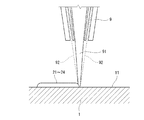
本実施形態では、LMDを行うために、図3に示すようなLMD装置が用いられる(他工程でも同様)。LMD装置は、ワーク1の表面11にノズル9からレーザ光91を放出して表面11を溶融しながら金属粉体92を噴射する。レーザ光91の光軸方向は、鉛直方向である。このようにして、第1堤防2を構成する4本のビード(長辺ビード21,22および短辺ビード23,24)を形成する。ただし、LMD用の供給金属は必ずしも金属粉体92である必要はなく、例えばワイヤであってもよい。
In this embodiment, an LMD apparatus as shown in FIG. 3 is used to perform LMD (the same applies to other steps). The LMD apparatus emits a
ワーク1を構成する材料は特に限定されるものではないが、例えば、ワーク1はチタン合金からなる。供給金属は、ワーク1と同一の組成を有してもよいし、異なる組成を有してもよい。例えば、ワーク1がチタン合金からなる場合は、供給金属はワーク1と同一または異なるチタン合金であってもよいし、チタン合金以外の合金であってもよい。
The material constituting the
第1堤防2を構成するビード21〜24は、比較的に小さいものである。例えば、第1堤防2を構成するビード21〜24は、後述する初層3を構成するビード31〜36よりも小さいことが望ましい。このような小さいビード21〜24は、例えば、レーザの出力を小さくするか、供給金属の供給量を少なくすることで形成することができる。
The
(2)初層形成工程
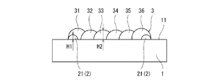
本工程では、図4に示すように、LMDにより、突起形成領域12(図1(a)参照)上に、第1堤防2を覆うように初層3を形成する。初層3は、平面状に並ぶ複数のビードで構成される。初層3を形成する際は、第1堤防2の内側に少なくとも2列のビードを形成することが望ましい。比較的に幅が広い突起8Aを形成することができるからである。本実施形態では、第1堤防2の長辺ビード21,22と平行な6つのビード31〜36を形成することで初層3を形成する。すなわち、両端に位置するビード31,36は第1堤防2の長辺ビード21,22の真上に位置する。その他の4つのビード32〜35は第1堤防2の内側に位置する。ただし、ビード31〜36は、第1堤防2の短辺ビード23,24と平行であってもよい。また、初層3を構成するビードの数は適宜変更可能である。
(2) Initial layer forming step In this step, as shown in FIG. 4, the
本実施形態では、ビードの個数と列数が一致しているが、必ずしもこれらは一致する必要はない。例えば、複数列のビードを1つのビードで形成してもよい(ジグザグ状のビードなど、個数としては1つだが、列数としては複数となるものを想定)。 In the present embodiment, the number of beads and the number of columns match, but they do not necessarily have to match. For example, a plurality of rows of beads may be formed by one bead (assuming that the number of beads is one, such as a zigzag-shaped bead, but the number of rows is multiple).
初層3を構成するビードであって第1堤防2を構成するビードの真上に位置するビードは、第1堤防2を構成するビードの少なくとも頂点を覆うように形成されることが望ましい。本実施形態では、初層3の両端に位置するビード31,36が、第1堤防2の長辺ビード21,22の少なくとも頂点を覆うように形成される。また、本実施形態では、品質の面から、全てのビード31〜36がほぼ同じLMD条件で形成される。このため、両端に位置するビード31,36の頂点は、第1堤防2の内側に位置するビード32〜35の頂点よりも高い。すなわち、初層3の表面は、周縁に向かって盛り上がっている。
It is desirable that the beads forming the
初層3を構成するビードであって第1堤防2を構成するビードの真上に位置するビード(本実施形態では、ビード31,36のそれぞれ)は、当該ビードの中心が第1堤防2を構成するビード(本実施形態では、長辺ビード(21または22))の中心と一致する位置から内側に位置するように形成されることが望ましい。これにより、初層3の表面を、周縁に向かって効率的に盛り上げることができる。例えば、初層3を構成するビードのうち第1堤防2を構成するビードの真上に位置するビードは、当該ビードの外側エッジが第1堤防2を構成するビードの外側エッジと一致するように形成されてもよい。
The bead that constitutes the
図4では、ビード31〜36が左側から右側に向かう順に形成される場合を示すが、ビード31〜36の形成順はこれに限られない。例えば、両端に位置するビード31,36が先に形成され、その後にビード32,35が形成され、最後にビード33,34が形成されてもよい。なお、ビードの形成順が図4に示す例に限定されない点は、後述する第1嵩上げ層4、中間ベース層6および第2嵩上げ層7でも同様である。
FIG. 4 shows a case where the
第1堤防2の高さH1は、第1堤防2の内側に位置するビード32〜35の高さH2の20%以上であることが望ましい。H1<0.2×H2であれば、初層3の表面における周縁に向かった盛り上がりが不十分となるおそれがあるからである。なお、第1堤防2は、例えば、0.1×H2の高さのビードを2つ積み上げて0.2×H2の高さとしてもよい。より望ましくは、第1堤防2の高さH1は、ビード32〜35の高さH2の40%以上である。また、第1堤防2の高さH1は、第1堤防2の内側に位置するビード32〜35の高さH2よりも低いことが望ましい(H1<H2)。
It is desirable that the height H1 of the
(3)第1嵩上げ層形成工程
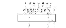
本工程では、図5に示すように、LMDにより、初層3上に少なくとも1つの第1嵩上げ層4を積層する。各第1嵩上げ層4は、平面状に並ぶ複数のビードで構成される。本実施形態では、初層3と同様に、第1堤防2の長辺ビード21,22と平行な6つのビード41〜46を形成することで各第1嵩上げ層4を形成する。つまり、ビード41〜46は、それぞれ初層3を構成するビード31〜36の真上に位置する。本実施形態では、第1嵩上げ層4の数は1つであるが、第1嵩上げ層4の数は複数であってもよい。
(3) First Raised Layer Forming Step In this step, as shown in FIG. 5, at least one first raised
第1嵩上げ層4は、当該第1嵩上げ層4の周縁が初層3の周縁に一致するように形成される。つまり、第1嵩上げ層4と初層3とは、ほぼ同じ大きさで重なり合っている。
The first raised
(4)第2堤防形成工程
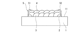
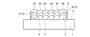
本工程では、図6に示すように、LMDにより、第1嵩上げ層4の周縁に沿って第2堤防5を形成する。換言すれば、第2堤防5は、第1嵩上げ層4の輪郭を内側からなぞるように形成される。上述したように突起形成領域12が矩形状であるため、第2堤防5は第1堤防2と同様に環状である。
(4) Second Embankment Forming Step In this step, as shown in FIG. 6, the
第2堤防5を構成するビードは、比較的に小さいものである。例えば、第2堤防5を構成するビードは、第1嵩上げ層4を構成するビード41〜46および後述する中間ベース層6を構成するビード61〜66よりも小さいことが望ましい。このため、第2堤防5の長辺ビード51,52は、第1嵩上げ層4の両端に位置するビード41,46の外側部分のみを覆い、ビード41,46の内側部分が露出している。このような小さいビードは、例えば、レーザの出力を小さくするか、供給金属の供給量を少なくすることで形成することができる。
The beads constituting the
第2堤防5を構成するビードのうち少なくとも長辺ビード51,52の頂点は、第1嵩上げ層4を構成するビード41〜46のどのビードの頂点よりも高い位置にある。
Of the beads constituting the
(5)中間ベース層形成工程
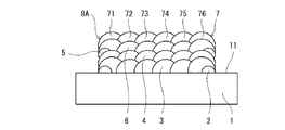
本工程では、図7に示すように、LMDにより、第1嵩上げ層4上に、第2堤防5を覆うように中間ベース層6を形成する。中間ベース層6は、平面状に並ぶ複数のビードで構成される。より詳しくは、初層3と同様に、第1堤防2の長辺ビード21,22と平行な6つのビード61〜66を形成することで中間ベース層6を形成する。
(5) Intermediate Base Layer Forming Step In this step, as shown in FIG. 7, an
つまり、両端に位置するビード61,66が第2堤防5の長辺ビード51,52の真上に位置し、その他の4つのビード62〜65が第2堤防5の内側に位置する。中間ベース層6を構成するビードのうち第2堤防5を構成するビードの真上に位置するビードは、第2堤防5を構成するビードの少なくとも頂点を覆うように形成されることが望ましい。本実施形態では、中間ベース層6の両端に位置するビード61,66が、第2堤防5の長辺ビード51,52の少なくとも頂点を覆うように形成される。また、本実施形態では、品質の面から、全てのビード61〜66がほぼ同じLMD条件で形成される。このため、両端に位置するビード61,66の頂点は、第2堤防5の内側に位置するビード62〜65の頂点よりも高い。すなわち、中間ベース層6の表面は、周縁に向かって盛り上がっている。
That is, the
中間ベース層6を構成するビードのうち第2堤防5を構成するビードの真上に位置するビード(本実施形態では、ビード61,66のそれぞれ)は、当該ビードの中心が第2堤防5を構成するビード(本実施形態では、長辺ビード(51または52))の中心と一致する位置から内側に位置するように形成されることが望ましい。これにより、中間ベース層6の表面を、周縁に向かって効率的に盛り上げることができる。例えば、中間ベース層6を構成するビードのうち第2堤防5を構成するビードの真上に位置するビードは、当該ビードの外側エッジが第2堤防5を構成するビードの外側エッジと一致するように形成されてもよい。
Of the beads constituting the
(6)第2嵩上げ層形成工程
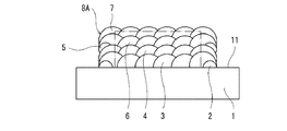
本工程では、図8に示すように、LMDにより、中間ベース層6上に少なくとも1つの第2嵩上げ層7を積層する。各第2嵩上げ層7は、平面状に並ぶ複数のビードで構成される。本実施形態では、初層3と同様に、第1堤防2の長辺ビード21,22と平行な6つのビード71〜76を形成することで各第2嵩上げ層7を形成する。つまり、ビード71〜76は、それぞれ中間ベース層6を構成するビード61〜66の真上に位置する。本実施形態では、第2嵩上げ層7の数は1つであるが、第2嵩上げ層7の数は複数であってもよい。
(6) Second Raised Layer Forming Step In this step, as shown in FIG. 8, at least one second raised
第2嵩上げ層7は、当該第2嵩上げ層7の周縁が中間ベース層6の周縁に一致するように形成される。つまり、第2嵩上げ層7と中間ベース層6とは、ほぼ同じ大きさで重なり合っている。
The second raised
以上の工程により、突起8Aを形成することができる。また、第2堤防形成工程、中間ベース層形成工程および第2嵩上げ層形成工程を繰り返せば、高さの高い突起8Aを形成することができる。
By the above steps, the
突起8Aが付加されたワーク1はそのまま製品として使用されてもよいが、図9中に二点鎖線で示すように、突起8Aの完成後に、第1堤防2および第2堤防5を取り除くように、突起8Aを機械加工してもよい。この構成によれば、突起8Aを機械加工することによって削り出される最終凸部に高い強度を確保することができる。突起8Aまたは最終凸部を有する製品は、部品として機械に組み込まれてもよい。
The
以上説明したように、本実施形態の突起形成方法では、第1堤防2を覆うように形成された初層3上に第1嵩上げ層4が積層されるので、第1嵩上げ層4を形成する際のエッジでの溶融部の流下が初層3を介して第1堤防2で抑制される。従って、第1嵩上げ層4の周縁を初層3の周縁に一致させることができる。さらに、第1嵩上げ層4の周縁に沿って第2堤防5が形成され、その第2堤防5を覆うように形成された中間ベース層6上に第2嵩上げ層7が積層されるので、第2嵩上げ層7を形成する際のエッジでの溶融部の流下が中間ベース層6を介して第2堤防5で抑制される。従って、第2嵩上げ層7の周縁を中間ベース層6の周縁に一致させることができる。これにより、ほぼ一定の幅で立ち上がる突起8Aを形成することができる。
As described above, in the protrusion forming method of the present embodiment, the first raised
しかも、本実施形態では、各層(特に、第1嵩上げ層4および第2嵩上げ層7)の表面をほぼフラットに保つことができるため、レーザの焦点を各層の表面に維持することができる。これにより、各層表面への入熱が安定し、供給金属の溶け残りや未溶融領域が発生しない。従って、供給金属の溶け残りに起因するポロシティ等の欠陥も発生せずに、内部品質が安定する。
Moreover, in the present embodiment, the surface of each layer (particularly, the first raised
図10に、第2堤防形成工程、中間ベース層形成工程および第2嵩上げ層形成工程を繰り返すことによって形成した突起8Aを示す。図10に示す例では、トータルで40層とすることで、高さ約50mmの、直方体形の突起8Aを形成することができた。
FIG. 10 shows a
<変形例>
前記実施形態では、互いに平行な直線状のビードによって各層が構成されていたが、各層を構成するビードは直線状に限られない。例えば、突起8Aが平面視で円形状である場合、各層は、同心円状の複数のビードで構成されてもよいし、連続する螺旋状のビードで構成されてもよい。例えば、初層3が連続する螺旋状のビードで構成される場合、第1堤防2の内側でビードが1周以上周回していれば、ビードは1つであるものの、第1堤防2の内側に2列以上のビードが形成されることになる。
<Modification example>
In the above embodiment, each layer is composed of linear beads parallel to each other, but the beads constituting each layer are not limited to the linear shape. For example, when the
(第2実施形態)
本発明の第2実施形態に係る突起形成方法は、図11に示すようにワーク1の表面11にフランジ状の突起8Bを形成する方法である。すなわち、本実施形態では、ワーク1が筒状であり、ワーク1の表面11がワーク1の内周面である。ただし、ワーク1の表面11は、ワーク1の外周面であってもよい。
(Second Embodiment)
The protrusion forming method according to the second embodiment of the present invention is a method of forming a flange-shaped
本実施形態では、第1実施形態と同様にして、図12に示すように、第1堤防2、初層3、第1嵩上げ層4、第2堤防5、中間ベース層6および第2嵩上げ層7を形成する。
ただし、突起8Bがフランジ状であるため、突起形成領域12は周方向に連続するリング状である。このため、第1堤防2は、ワーク1の軸方向で互いに対向する一対のビード25,26を含む。同様に、第2堤防5も、ワーク1の軸方向で互いに対向する一対のビード55,56を含む。
In the present embodiment, as in the first embodiment, as shown in FIG. 12, the
However, since the
さらに、本実施形態では、ワーク1の表面11が円錐状である。そして、第1堤防2の大径側のビード26の高さは、小径側のビード25の高さよりも高く設定されている。この構成によれば、円錐面に対して良好に突起を形成することができる。
Further, in the present embodiment, the
本実施形態でも、第1実施形態と同様に、ほぼ一定の幅で立ち上がる突起8Bを形成することができる。
Also in the present embodiment, as in the first embodiment, the
(その他の実施形態)
本発明は上述した実施形態に限定されるものではなく、本発明の要旨を逸脱しない範囲で種々の変形が可能である。
(Other embodiments)
The present invention is not limited to the above-described embodiment, and various modifications can be made without departing from the gist of the present invention.
例えば、第1堤防2を構成するビードおよび第2堤防5を構成するビードのそれぞれは、必ずしも連続している必要はなく、断続的であってもよい。
For example, the beads constituting the
また、第1実施形態のように柱状の突起8Aを形成する場合であって、ワーク1の表面が水平面に対して傾斜している場合には、第1堤防2を形成する際に、第2実施形態と同様に、下方に位置するビードを上方に位置するビードよりも大きくすれば、傾斜面に対して良好に突起を形成することができる。
Further, when the
1 ワーク
11 表面
12 突起形成領域
2 第1堤防
21〜26 ビード
3 初層
31〜36 ビード
4 第1嵩上げ層
5 第2堤防
55,56 ビード
6 中間ベース層
7 第2嵩上げ層
8A,8B 突起
1
Claims (8)
レーザ金属肉盛により、前記ワークの表面上の突起形成領域を囲うように第1堤防を形成する工程と、
レーザ金属肉盛により、前記突起形成領域上に、前記第1堤防を覆うように初層を形成する工程と、
レーザ金属肉盛により、前記初層上に少なくとも1つの第1嵩上げ層を積層する工程と、
レーザ金属肉盛により、前記少なくとも1つの第1嵩上げ層の周縁に沿って第2堤防を形成する工程と、
レーザ金属肉盛により、前記少なくとも1つの第1嵩上げ層上に、前記第2堤防を覆うように中間ベース層を形成する工程と、
レーザ金属肉盛により、前記中間ベース層上に少なくとも1つの第2嵩上げ層を積層する工程と、を含み、
前記初層を構成するビードであって前記第1堤防を構成するビードの真上に位置するビードは、前記第1堤防を構成するビードの少なくとも頂点を覆うように形成される、突起形成方法。 It is a method of forming protrusions on the surface of the work.
A step of forming a first embankment so as to surround a protrusion forming region on the surface of the work by laser metal overlay, and
A step of forming an initial layer on the protrusion forming region by laser metal overlay so as to cover the first embankment.
A step of laminating at least one first raised layer on the first layer by laser metal overlay, and
A step of forming a second embankment along the peripheral edge of at least one of the first raised layers by laser metal overlay.
A step of forming an intermediate base layer on the at least one first raised layer by laser metal overlay so as to cover the second embankment.
Including a step of laminating at least one second raised layer on the intermediate base layer by laser metal overlay.
A method for forming a protrusion, wherein the bead constituting the first layer and located directly above the bead constituting the first embankment is formed so as to cover at least the apex of the bead constituting the first embankment.
前記第1堤防および前記第2堤防のそれぞれは、前記ワークの軸方向で互いに対向する一対のビードを含む、請求項1に記載の突起形成方法。 The work has a tubular shape, the surface of the work is an inner peripheral surface or an outer peripheral surface of the work, and the protrusion forming region has a ring shape continuous in the circumferential direction.
The method for forming a protrusion according to claim 1, wherein each of the first embankment and the second embankment includes a pair of beads facing each other in the axial direction of the work.
レーザ金属肉盛により、前記ワークの表面上の周方向に連続するリング状の突起形成領域を囲うように、前記ワークの軸方向で互いに対向する一対のビードを含む第1堤防を形成する工程と、
レーザ金属肉盛により、前記突起形成領域上に、前記第1堤防を覆うように初層を形成する工程と、
レーザ金属肉盛により、前記初層上に少なくとも1つの第1嵩上げ層を積層する工程と、
レーザ金属肉盛により、前記少なくとも1つの第1嵩上げ層の周縁に沿って、前記ワークの軸方向で互いに対向する一対のビードを含む第2堤防を形成する工程と、
レーザ金属肉盛により、前記少なくとも1つの第1嵩上げ層上に、前記第2堤防を覆うように中間ベース層を形成する工程と、
レーザ金属肉盛により、前記中間ベース層上に少なくとも1つの第2嵩上げ層を積層する工程と、を含み、
前記ワークの表面は円錐状であり、
前記第1堤防の前記一対のビードのうち大径側のビードの高さは小径側のビードの高さよりも高い、突起形成方法。 A method of forming protrusions on the inner peripheral surface or outer peripheral surface of a tubular work.
A step of forming a first embankment containing a pair of beads facing each other in the axial direction of the work so as to surround a ring-shaped protrusion forming region continuous in the circumferential direction on the surface of the work by laser metal overlay. ,
A step of forming an initial layer on the protrusion forming region by laser metal overlay so as to cover the first embankment.
A step of laminating at least one first raised layer on the first layer by laser metal overlay, and
A step of forming a second embankment containing a pair of beads facing each other in the axial direction of the work along the peripheral edge of the at least one first raised layer by laser metal overlay.
A step of forming an intermediate base layer on the at least one first raised layer by laser metal overlay so as to cover the second embankment.
Including a step of laminating at least one second raised layer on the intermediate base layer by laser metal overlay.
The surface of the work is conical and has a conical shape.
A method for forming a protrusion, wherein the height of the bead on the large diameter side of the pair of beads on the first embankment is higher than the height of the bead on the small diameter side.
レーザ金属肉盛により、前記ワークの表面上の突起形成領域を囲うように第1堤防を形成する工程と、
レーザ金属肉盛により、前記突起形成領域上に、前記第1堤防を覆うように初層を形成する工程と、
レーザ金属肉盛により、前記初層上に少なくとも1つの第1嵩上げ層を積層する工程と、
レーザ金属肉盛により、前記少なくとも1つの第1嵩上げ層の周縁に沿って第2堤防を形成する工程と、
レーザ金属肉盛により、前記少なくとも1つの第1嵩上げ層上に、前記第2堤防を覆うように中間ベース層を形成する工程と、
レーザ金属肉盛により、前記中間ベース層上に少なくとも1つの第2嵩上げ層を積層する工程と、を含み、
前記初層を形成する際は、前記第1堤防の内側に少なくとも2列のビードを形成し、
前記第1堤防の高さは、前記少なくとも2列のビードの高さの20%以上である、突起形成方法。 It is a method of forming protrusions on the surface of the work.
A step of forming a first embankment so as to surround a protrusion forming region on the surface of the work by laser metal overlay, and a step of forming the first embankment.
A step of forming an initial layer on the protrusion forming region by laser metal overlay so as to cover the first embankment.
A step of laminating at least one first raised layer on the first layer by laser metal overlay, and
A step of forming a second embankment along the peripheral edge of at least one of the first raised layers by laser metal overlay.
A step of forming an intermediate base layer on the at least one first raised layer by laser metal overlay so as to cover the second embankment.
Including a step of laminating at least one second raised layer on the intermediate base layer by laser metal overlay.
When forming the first layer, at least two rows of beads are formed inside the first embankment.
The protrusion forming method, wherein the height of the first embankment is 20% or more of the height of the beads in at least two rows.
Priority Applications (4)
| Application Number | Priority Date | Filing Date | Title |
|---|---|---|---|
| JP2016252570A JP6845686B2 (en) | 2016-12-27 | 2016-12-27 | Protrusion formation method |
| PCT/JP2017/045992 WO2018123820A1 (en) | 2016-12-27 | 2017-12-21 | Method for forming protrusion and machine |
| EP17888881.4A EP3563966B1 (en) | 2016-12-27 | 2017-12-21 | Projection forming method |
| US16/474,373 US11420291B2 (en) | 2016-12-27 | 2017-12-21 | Projection forming method and machine |
Applications Claiming Priority (1)
| Application Number | Priority Date | Filing Date | Title |
|---|---|---|---|
| JP2016252570A JP6845686B2 (en) | 2016-12-27 | 2016-12-27 | Protrusion formation method |
Publications (3)
| Publication Number | Publication Date |
|---|---|
| JP2018103225A JP2018103225A (en) | 2018-07-05 |
| JP2018103225A5 JP2018103225A5 (en) | 2020-01-30 |
| JP6845686B2 true JP6845686B2 (en) | 2021-03-24 |
Family
ID=62708140
Family Applications (1)
| Application Number | Title | Priority Date | Filing Date |
|---|---|---|---|
| JP2016252570A Active JP6845686B2 (en) | 2016-12-27 | 2016-12-27 | Protrusion formation method |
Country Status (4)
| Country | Link |
|---|---|
| US (1) | US11420291B2 (en) |
| EP (1) | EP3563966B1 (en) |
| JP (1) | JP6845686B2 (en) |
| WO (1) | WO2018123820A1 (en) |
Families Citing this family (2)
| Publication number | Priority date | Publication date | Assignee | Title |
|---|---|---|---|---|
| JP7411366B2 (en) * | 2019-09-27 | 2024-01-11 | 三菱重工コンプレッサ株式会社 | Metal additive manufacturing method |
| CN114016018B (en) * | 2021-11-05 | 2023-07-04 | 江苏徐工工程机械研究院有限公司 | Workpiece with composite coating and method of manufacturing the same |
Family Cites Families (9)
| Publication number | Priority date | Publication date | Assignee | Title |
|---|---|---|---|---|
| US4903888A (en) * | 1988-05-05 | 1990-02-27 | Westinghouse Electric Corp. | Turbine system having more failure resistant rotors and repair welding of low alloy ferrous turbine components by controlled weld build-up |
| EP0496181B1 (en) * | 1991-01-21 | 1998-08-19 | Sulzer Hydro AG | Method of fabricating metallic workpieces with a welding apparatus, and apparatus for carrying out the method |
| US6144008A (en) * | 1996-11-22 | 2000-11-07 | Rabinovich; Joshua E. | Rapid manufacturing system for metal, metal matrix composite materials and ceramics |
| JP4551082B2 (en) | 2003-11-21 | 2010-09-22 | 三菱重工業株式会社 | Welding method |
| US9292016B2 (en) * | 2007-10-26 | 2016-03-22 | Ariel Andre Waitzman | Automated welding of moulds and stamping tools |
| US8618434B2 (en) * | 2010-03-22 | 2013-12-31 | Siemens Energy, Inc. | Superalloy repair welding using multiple alloy powders |
| US9289845B2 (en) * | 2012-11-07 | 2016-03-22 | David S. Henn | Metal deposition of exterior members in oil field tubulars |
| JP6114718B2 (en) * | 2014-06-17 | 2017-04-12 | 川崎重工業株式会社 | Axisymmetric body and method of manufacturing axisymmetric product |
| JP6887755B2 (en) * | 2016-02-16 | 2021-06-16 | 株式会社神戸製鋼所 | Stacking control device, stacking control method and program |
-
2016
- 2016-12-27 JP JP2016252570A patent/JP6845686B2/en active Active
-
2017
- 2017-12-21 US US16/474,373 patent/US11420291B2/en active Active
- 2017-12-21 EP EP17888881.4A patent/EP3563966B1/en active Active
- 2017-12-21 WO PCT/JP2017/045992 patent/WO2018123820A1/en unknown
Also Published As
| Publication number | Publication date |
|---|---|
| JP2018103225A (en) | 2018-07-05 |
| US11420291B2 (en) | 2022-08-23 |
| WO2018123820A1 (en) | 2018-07-05 |
| EP3563966B1 (en) | 2022-02-16 |
| EP3563966A4 (en) | 2020-10-07 |
| US20190344388A1 (en) | 2019-11-14 |
| EP3563966A1 (en) | 2019-11-06 |
Similar Documents
| Publication | Publication Date | Title |
|---|---|---|
| KR101715475B1 (en) | Laser welding method | |
| JP6846619B2 (en) | Laser welding method | |
| JP6845686B2 (en) | Protrusion formation method | |
| CN112743834B (en) | Multi-laser cooperative load laser selective melting additive manufacturing method | |
| US20130136868A1 (en) | Selective laser melting / sintering using powdered flux | |
| CN105246644A (en) | Localized repair of superalloy component | |
| US20150033559A1 (en) | Repair of a substrate with component supported filler | |
| CN106660175A (en) | Axially symmetric body, and axially symmetric body manufacturing method | |
| US10722989B2 (en) | Turbine rotor disc repairing method | |
| KR20150122083A (en) | Welding method and welding structure | |
| WO2011142324A1 (en) | Method of producing superconducting accelerator cavity | |
| JP7020321B2 (en) | Joining structure between plates | |
| JP2016030283A (en) | Metallic member and method of manufacturing the same | |
| JP2017214229A (en) | crucible | |
| CN110814344B (en) | Profile processing method based on selective laser melting | |
| CN101862900A (en) | Welding method and welding device | |
| JP2012223799A (en) | Method of manufacturing welded joint | |
| WO2020085194A1 (en) | Inclined structure and manufacturing method therefor | |
| JP6400916B2 (en) | Manufacturing method of joined body | |
| EP3572180B1 (en) | Method of laser welding of metal plates | |
| JP6759749B2 (en) | Welding method and manufacturing method of welded products | |
| JP6059107B2 (en) | Method for manufacturing control rod for nuclear reactor | |
| US20180281114A1 (en) | Method for build-up welding with oscillating solidification front by defining parameters of the build-up welding | |
| JP2010167428A (en) | Laser beam welding method | |
| JP7185436B2 (en) | Laser processing method |
Legal Events
| Date | Code | Title | Description |
|---|---|---|---|
| A521 | Request for written amendment filed |
Free format text: JAPANESE INTERMEDIATE CODE: A523 Effective date: 20191210 |
|
| A621 | Written request for application examination |
Free format text: JAPANESE INTERMEDIATE CODE: A621 Effective date: 20191210 |
|
| A131 | Notification of reasons for refusal |
Free format text: JAPANESE INTERMEDIATE CODE: A131 Effective date: 20200901 |
|
| A521 | Request for written amendment filed |
Free format text: JAPANESE INTERMEDIATE CODE: A523 Effective date: 20201029 |
|
| A131 | Notification of reasons for refusal |
Free format text: JAPANESE INTERMEDIATE CODE: A131 Effective date: 20201124 |
|
| A521 | Request for written amendment filed |
Free format text: JAPANESE INTERMEDIATE CODE: A523 Effective date: 20210120 |
|
| TRDD | Decision of grant or rejection written | ||
| A01 | Written decision to grant a patent or to grant a registration (utility model) |
Free format text: JAPANESE INTERMEDIATE CODE: A01 Effective date: 20210202 |
|
| A61 | First payment of annual fees (during grant procedure) |
Free format text: JAPANESE INTERMEDIATE CODE: A61 Effective date: 20210226 |
|
| R150 | Certificate of patent or registration of utility model |
Ref document number: 6845686 Country of ref document: JP Free format text: JAPANESE INTERMEDIATE CODE: R150 |
|
| R250 | Receipt of annual fees |
Free format text: JAPANESE INTERMEDIATE CODE: R250 |


