JP4537266B2 - Recording apparatus and reproducing apparatus - Google Patents
Recording apparatus and reproducing apparatus Download PDFInfo
- Publication number
- JP4537266B2 JP4537266B2 JP2005176872A JP2005176872A JP4537266B2 JP 4537266 B2 JP4537266 B2 JP 4537266B2 JP 2005176872 A JP2005176872 A JP 2005176872A JP 2005176872 A JP2005176872 A JP 2005176872A JP 4537266 B2 JP4537266 B2 JP 4537266B2
- Authority
- JP
- Japan
- Prior art keywords
- stream
- moving image
- chunk
- recording
- data
- Prior art date
- Legal status (The legal status is an assumption and is not a legal conclusion. Google has not performed a legal analysis and makes no representation as to the accuracy of the status listed.)
- Active
Links
Images


Classifications
-
- H—ELECTRICITY
- H04—ELECTRIC COMMUNICATION TECHNIQUE
- H04N—PICTORIAL COMMUNICATION, e.g. TELEVISION
- H04N5/00—Details of television systems
- H04N5/76—Television signal recording
- H04N5/78—Television signal recording using magnetic recording
- H04N5/782—Television signal recording using magnetic recording on tape
- H04N5/783—Adaptations for reproducing at a rate different from the recording rate
-
- H—ELECTRICITY
- H04—ELECTRIC COMMUNICATION TECHNIQUE
- H04N—PICTORIAL COMMUNICATION, e.g. TELEVISION
- H04N5/00—Details of television systems
- H04N5/76—Television signal recording
- H04N5/765—Interface circuits between an apparatus for recording and another apparatus
- H04N5/77—Interface circuits between an apparatus for recording and another apparatus between a recording apparatus and a television camera
- H04N5/772—Interface circuits between an apparatus for recording and another apparatus between a recording apparatus and a television camera the recording apparatus and the television camera being placed in the same enclosure
-
- H—ELECTRICITY
- H04—ELECTRIC COMMUNICATION TECHNIQUE
- H04N—PICTORIAL COMMUNICATION, e.g. TELEVISION
- H04N9/00—Details of colour television systems
- H04N9/79—Processing of colour television signals in connection with recording
- H04N9/80—Transformation of the television signal for recording, e.g. modulation, frequency changing; Inverse transformation for playback
- H04N9/804—Transformation of the television signal for recording, e.g. modulation, frequency changing; Inverse transformation for playback involving pulse code modulation of the colour picture signal components
- H04N9/8042—Transformation of the television signal for recording, e.g. modulation, frequency changing; Inverse transformation for playback involving pulse code modulation of the colour picture signal components involving data reduction
-
- H—ELECTRICITY
- H04—ELECTRIC COMMUNICATION TECHNIQUE
- H04N—PICTORIAL COMMUNICATION, e.g. TELEVISION
- H04N9/00—Details of colour television systems
- H04N9/79—Processing of colour television signals in connection with recording
- H04N9/80—Transformation of the television signal for recording, e.g. modulation, frequency changing; Inverse transformation for playback
- H04N9/82—Transformation of the television signal for recording, e.g. modulation, frequency changing; Inverse transformation for playback the individual colour picture signal components being recorded simultaneously only
- H04N9/8205—Transformation of the television signal for recording, e.g. modulation, frequency changing; Inverse transformation for playback the individual colour picture signal components being recorded simultaneously only involving the multiplexing of an additional signal and the colour video signal
- H04N9/8211—Transformation of the television signal for recording, e.g. modulation, frequency changing; Inverse transformation for playback the individual colour picture signal components being recorded simultaneously only involving the multiplexing of an additional signal and the colour video signal the additional signal being a sound signal
Description
本発明は、記録装置及び再生装置に関し、より具体的には、記録途中に映像フレームレートを切り替え可能な記録装置と、映像フレームレートを切り替えて記録された映像を再生する再生装置に関する。 The present invention relates to a recording device and a playback device, and more specifically to a recording device that can switch a video frame rate during recording and a playback device that plays back a recorded video by switching the video frame rate.
デジタルカメラの撮像素子には、CCDセンサ又はCMOSセンサが使用される。CMOSセンサはCCDセンサに比べて、消費電流が少ないこと、データの読み出しが高速であることなどの利点がある。この利点を利用して、CMOSセンサを高速に駆動し、高速なフレームレートで動画をキャプチャすることが可能となってきた。 A CCD sensor or a CMOS sensor is used as an image sensor of the digital camera. Compared with a CCD sensor, a CMOS sensor has advantages such as low current consumption and high-speed data reading. Taking advantage of this advantage, it has become possible to drive a CMOS sensor at high speed and capture a moving image at a high frame rate.
特許文献1には、撮像素子、A/D変換手段、信号処理手段及び画像信号圧縮手段からなる撮像系においてフレームレートを可変にする動画撮像システムが記載されている。
一方、デジタルカメラでの動画撮影は、撮影した動画ストリームデータをAVI(Audio Video Interleaved)ファイル形式などに加工して記録メディアに書き込む。撮影された動画データのレートは、通常、記録メディアへの書込みデータレートよりも高速である。その差を補償するために、種々の画像圧縮技術が採用され、且つ、記録メディアの前段に大容量のバッファが配置される。
近年の動画撮影では、長時間撮影を行いたいという要求と、高速フレームレートで撮影を行いたいという要求がある。バッファへのデータ書込み速度がバッファから記録メディアへのデータ読み出し速度を上回るような高速フレームレートの撮影では、バッファにデータを書き込みしきれないことがあるので、1回の撮影継続時間は、バッファの容量により制限され、一般に極めて短くなる。他方、バッファが溢れない程の低速フレームレートの撮影では、1回の撮影継続時間は、記録メディアの容量で制限される。従って、長時間撮影と高速フレームレート撮影を両立することは、困難である。 In recent moving image shooting, there is a request for shooting for a long time and a request for shooting at a high frame rate. When shooting at a high frame rate such that the data writing speed to the buffer exceeds the data reading speed from the buffer to the recording medium, it may not be possible to write the data into the buffer. Limited by capacity and generally very short. On the other hand, in shooting at a low frame rate that does not overflow the buffer, the duration of one shooting is limited by the capacity of the recording medium. Therefore, it is difficult to achieve both long-time shooting and high-speed frame rate shooting.
撮影中の特定のシーンにおいて高速フレームレートの撮影を希望することがある。しかし、動画データの既存のファイルフォーマットは、記録途中でのフレームレートの変更をサポートしていない。仮に、記録途中でフレームレートを変更して記録したとしても、再生時には、何れか1つのフレームレートで再生されてしまう。例えば、低速のフレームレートで記録されている区間は通常のスピードで再生され、高速のフレームレートで記録されている区間はスローモーションで再生されることになる There is a case where it is desired to shoot at a high frame rate in a specific scene being shot. However, the existing file format of moving image data does not support changing the frame rate during recording. Even if the recording is performed while changing the frame rate in the middle of recording, at the time of reproduction, reproduction is performed at any one frame rate. For example, a section recorded at a low frame rate is played back at normal speed, and a section recorded at a high frame rate is played back in slow motion.
従って、従来、記録途中にフレームレートを変更することは、希望通りに再生できないという意味で、実質的に不可能であった。 Therefore, conventionally, changing the frame rate during recording has been virtually impossible in the sense that it cannot be reproduced as desired.
そこで、本発明は、記録途中のフレームレートの変更を実質的に可能にする記録装置及び再生装置を提示することを目的とする。 Therefore, an object of the present invention is to provide a recording apparatus and a reproducing apparatus that can substantially change the frame rate during recording.
上記の目的を達成するために、本発明に係る記録装置は、画像信号を入力する画像入力手段と、マイクにより得られた音声信号を入力する音声入力手段と、前記画像入力手段により入力された画像信号を用いて、第1のフレームレートの第1の動画像信号または、前記第1のフレームレートよりも高い第2のフレームレートの第2の動画像信号を生成するとともに、生成した前記第1の動画像信号または前記第2の動画像信号と、音声信号とからなるストリームを生成するストリーム生成手段と、前記ストリーム生成手段により生成されたストリームを記録媒体に記録する記録手段と、前記第2の動画像信号の生成を指示する指示手段とを備え、前記ストリーム生成手段は、前記第1の動画像信号と前記音声入力手段により入力された前記音声信号とからなる第1のストリームを生成しているときに、前記指示手段により指示がされたことに応じて、前記第1のストリームに代えて、前記第2の動画像信号と無音を示す音声信号とからなる第2のストリームを生成することを特徴とする。 To achieve the above object, a recording apparatus according to the present invention is input and the image input means for inputting the images signals, an audio input means for inputting the audio signal obtained by the microphone, by the image input means by using the images signal, the first moving image signal in a first frame rate or, to generate a second moving image signal of the first frame higher second frame rate than was generated It is recorded on the first moving image signal or the second moving image signal, and the stream generation unit that forms the raw Luz stream-such from an audio signal, the recording medium stream generated by said stream generating means a recording unit, and an instruction means for instructing the generation of the second moving image signal, the stream generating means, the sound inputted by the first moving image signal and said audio input means When generating a first stream consisting of a signal, in response to the instruction has been by the instruction means, instead of the first stream, sound indicating the second moving image signal and the silence Generating a second stream of signals .
本発明に係る再生装置は,上述の記録装置で記録した動画ファイルを再生する再生装置であって、前記第1のインデックス情報と前記第2のインデックス情報とに基づいて、前記動画ファイルにおける前記第1の動画像信号の期間と前記第2の動画信号の期間を区別して表示装置に表示することを特徴とする。 A playback device according to the present invention is a playback device for playing back a moving image file recorded by the recording device described above, and based on the first index information and the second index information, the first moving image file in the moving image file. A period of one moving image signal and a period of the second moving image signal are distinguished from each other and displayed on a display device .
本発明によれば、長時間の動画撮影中に高速なフレームレートで撮影することができ、高速フレームレート区間を容易に検索することができる。すなわち、簡便な方法でフレームレートの切り替え期間を指定することができる。 According to the present invention, it is possible to shoot at a high frame rate during long-time moving image shooting, and it is possible to easily search for a high-speed frame rate interval. That is, the frame rate switching period can be designated by a simple method.
さらに、フレームレートを切り替えて動画記録した場合は、再生時のビデオデータと音声データの同期がずれないように管理することができる。 Furthermore, when moving images are recorded with the frame rate switched, it is possible to manage so that the synchronization of video data and audio data during reproduction does not shift.
以下、図面を参照して、本発明の好ましい実施例を詳細に説明する。 Hereinafter, preferred embodiments of the present invention will be described in detail with reference to the drawings.
図1は、本発明の第1実施例に係るデジタルカメラの概略構成ブロック図である。図1において、デジタルカメラ10は、レンズユニット12、絞り・シャッタ機構14、CCD撮像素子16、A/Dコンバータ18、SSGユニット20、信号処理ユニット22、DMAコントローラ24、DRAM26、フラッシュROM28、マイクロフォン30、A/Dコンバータ32、絞り制御装置34、レンズ制御装置36、CPU38、表示制御装置40、通信制御装置42、記録媒体制御装置44、電源となる電池46、電源制御装置48、DC/DCコンバータ50、入力装置52、表示装置54、通信コネクタ56、記録媒体58及びシステムバス60等を具備する。
FIG. 1 is a schematic block diagram of a digital camera according to a first embodiment of the present invention. In FIG. 1, a
CCD撮像素子16は、レンズユニット12及び絞り・シャッタ機構14による光学像を電気信号に変換する。A/Dコンバータ18は、CCD撮像素子16から出力されるアナログ電気信号をデジタル信号に変換する。SSGユニット20は、CCD撮像素子16とA/Dコンバータ18に同期信号を供給する。信号処理ユニット22は、圧縮及び伸長などの画像処理をする。DMAコントローラ24は、システムバス60を介した所定ブロック間の高速なデータ転送を実現する。DRAM26は、デジタルカメラ10の主記憶であり、撮影時にバッファメモリとしても使用される。フラッシュROM28は、ファームウエアプログラムを格納する。
The
マイクロフォン30は、デジタルカメラ10の外部音声を電気信号に変換する。A/Dコンバータ32は、マイクロフォン30のアナログ音声信号をデジタル信号に変換する。絞り制御装置34は、絞り・シャッタ機構14を制御する。レンズ制御装置36は、レンズユニット12に対してAF(オートフォーカス)とズーム等のレンズ駆動を行う。CPU38は、フラッシュROM28からロードしたファームウエアプログラムに従い、デジタルカメラ10の全体を制御する。
The
表示制御装置40は、TFT液晶等で構成される表示装置54を制御する。通信制御装置42は、USBプロトコルを用いた通信を制御する。通信コネクタ56は、USBケーブルを介して、外部のPCまたはプリンタ等と接続する。記録媒体制御装置44は、固体メモリカード、ハードディスク又は光ディスク等からなる記録媒体58に対して、データを読み出し、書き込む。
The
電源制御装置48は、DC/DCコンバータ50を制御し、電池46の残量を検出する。DC/DCコンバータ50は、電池46からの電力をデジタルカメラ10の各部に、適切な電圧に変換して供給する。
The power
入力装置52は、表示装置54上に表示されるメニュー画面に従い、ユーザが種々の指示又は選択を入力するのに使用される。入力装置52は、キーパッド、ズームレバー、電源スイッチ及びレリーズスイッチ等で構成されている。システムバス60は、各回路ブロック間の高速なデータ転送を実現する。
<AVI、RIFFの説明>
The
<Description of AVI and RIFF>
ここで、本実施例で使用するファイルフォーマットを説明する。 Here, the file format used in the present embodiment will be described.
AVIファイルは、RIFF(Resource Interchange File Format)と呼ばれるファイル形式で構成されている。RIFF形式とは、様々なリソースを一つのファイルにまとめて扱うためのファイル形式である。すなわち、RIFF形式は、新しいフォーマットが追加されても、基本的な構造を変えることなく、様々なタイプのファイルを扱うことができるという特徴を持つ。 The AVI file has a file format called RIFF (Resource Interchange File Format). The RIFF format is a file format for handling various resources in one file. That is, the RIFF format has a feature that even if a new format is added, various types of files can be handled without changing the basic structure.
RIFF形式のファイルフォーマットは、チャンク(chunk)と呼ばれるブロックを1つの単位として構成されている。チャンクは、4バイトの識別子、4バイトのサイズ情報及び任意長のデータ部からなる。識別子は、3文字以下の場合には、右詰めで余りにスペースが補充される。データ部の構造は、チャンクのタイプにより異なる。 The file format of the RIFF format is composed of blocks called chunks as one unit. The chunk includes a 4-byte identifier, 4-byte size information, and a data portion having an arbitrary length. If the identifier is 3 characters or less, it is right-justified and filled with spaces. The structure of the data part differs depending on the type of chunk.
特定のチャンクは、チャンクを含むことができる。この場合、チャンクはいわば親子の関係になり、チャンクを含むチャンクを親チャンクと呼び、含まれるチャンクをサブチャンクと呼ぶ。一つのチャンクに複数のサブチャンクを含ませることも可能である。 A particular chunk can include a chunk. In this case, the chunks are in a so-called parent-child relationship, and the chunk including the chunk is called a parent chunk, and the included chunk is called a sub chunk. It is possible to include a plurality of sub chunks in one chunk.
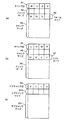
識別子RIFFで示されるRIFFチャンクは、RIFFファイルの先頭に配置される特別のチャンクである。識別子LISTで示されるLISTチャンクは、サブチャンクをリスト化したものである。図2(a)は、RIFFチャンクの構成を示し、図2(b)は、LISTチャンクの構成を示し、図2(c)は、一般のチャンクの一例としてstrhチャンクの構成を示す。 The RIFF chunk indicated by the identifier RIFF is a special chunk placed at the beginning of the RIFF file. The LIST chunk indicated by the identifier LIST is a list of sub chunks. FIG. 2A shows the configuration of the RIFF chunk, FIG. 2B shows the configuration of the LIST chunk, and FIG. 2C shows the configuration of the strh chunk as an example of a general chunk.
RIFFチャンクでは、図2(a)に示すように、最初の4バイト(A1)にチャンクID(識別子)として文字列”RIFF”が格納される。次の4バイト(A2)に、後続のデータ部(A4)のバイト長を示すチャンクサイズが格納される。データ部(A4)の先頭の4バイト(A3)には、このRIFFファイルに格納されるデータのファイル形式を示すフォームタイプが格納される。例えば、AVIデータの場合、フォームタイプA3に文字列”AVI ”が格納される。 In the RIFF chunk, as shown in FIG. 2A, a character string “RIFF” is stored as a chunk ID (identifier) in the first 4 bytes (A1). The chunk size indicating the byte length of the subsequent data portion (A4) is stored in the next 4 bytes (A2). In the first 4 bytes (A3) of the data part (A4), a form type indicating the file format of the data stored in the RIFF file is stored. For example, in the case of AVI data, the character string “AVI” is stored in the form type A3.
LISTチャンクでは、図2(b)に示すように、最初の4バイト(A5)にチャンクIDとして文字列”LIST”が格納される。次の4バイト(A6)に、後続のデータ部(A8)のバイト長を示すチャンクサイズが格納される。データ部(A8)の先頭の4バイト(A7)には、このLISTチャンクの意味又はタイプを示すリストタイプが格納される。図2(b)に示す例では、リストタイプとして、文字列”movi”が格納されている。LISTチャンクのリストタイプが、例えば”INFO”である場合、リストチャンクは、データ部A8に、著作権を示すICOPチャンクと、作成日を示すICRDチャンクを含むことができる。 In the LIST chunk, as shown in FIG. 2B, the character string “LIST” is stored as the chunk ID in the first 4 bytes (A5). In the next 4 bytes (A6), a chunk size indicating the byte length of the subsequent data portion (A8) is stored. A list type indicating the meaning or type of the LIST chunk is stored in the first 4 bytes (A7) of the data portion (A8). In the example shown in FIG. 2B, the character string “movi” is stored as the list type. When the list type of the LIST chunk is “INFO”, for example, the list chunk can include an ICOP chunk indicating copyright and an ICRD chunk indicating the creation date in the data part A8.
一般のチャンクは、図2(c)に示すように、最初の4バイト(A9)にチャンクID(図示例では、文字列”strh”)が格納される。次の4バイト(A10)に、後続のデータ部(A11)のバイト長を示すチャンクサイズが格納される。
<RIFF形式のAVIファイル>
As shown in FIG. 2C, a general chunk stores a chunk ID (a character string “strh” in the illustrated example) in the first 4 bytes (A9). The chunk size indicating the byte length of the subsequent data portion (A11) is stored in the next 4 bytes (A10).
<AVI file in RIFF format>
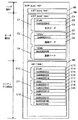
図3は、RIFF形式のAVIファイルの構造図を示す。ヘッダ部B1には、AVIファイルの属性情報に関わるデータが格納される。データ部B2には、AVIファイルの実際の音声データと画像データが格納される。インデックス部B3には、データ部B2に記録されている音声データと画像データの各ファイル上でのオフセット位置及びサイズが格納される。 FIG. 3 shows a structure diagram of an AVI file in the RIFF format. The header part B1 stores data related to the attribute information of the AVI file. The data portion B2 stores actual audio data and image data of the AVI file. The index part B3 stores the offset position and size of each of the audio data and image data recorded in the data part B2.
RIFFチャンクB4のフォームタイプは”AVI ”である。RIFFチャンクB4のチャンクデータ領域は、LISTチャンクB5、LISTチャンクB6、サブチャンクB7、LISTチャンクB8、及びサブチャンクB9から構成されている。LISTチャンクB5のリストタイプは”hdrl”であり、LISTチャンクB6のリストタイプは”INFO”である。サブチャンクB7のチャンクIDは”JUNK”であり、チャンクデータ領域にダミーデータを持つ。LISTチャンクB8のリストタイプは”movi”であり、サブチャンクB9のチャンクIDは”idx1”である。 The form type of the RIFF chunk B4 is “AVI”. The chunk data area of the RIFF chunk B4 includes a LIST chunk B5, a LIST chunk B6, a sub chunk B7, a LIST chunk B8, and a sub chunk B9. The list type of the LIST chunk B5 is “hdrl”, and the list type of the LIST chunk B6 is “INFO”. The chunk ID of the sub chunk B7 is “JUNK” and has dummy data in the chunk data area. The list type of the LIST chunk B8 is “movi”, and the chunk ID of the sub chunk B9 is “idx1”.
サブチャンクB7は、チャンクデータ領域にダミーデータを詰めることにより、ヘッダ領域B1のサイズを調整することができる。換言すると、適当な量のダミーデータを収容するJUNKチャンクを使用することで、ヘッダ部B1の長さ又はサイズを調整できる。 The sub chunk B7 can adjust the size of the header area B1 by filling the chunk data area with dummy data. In other words, the length or size of the header part B1 can be adjusted by using a JUNK chunk that accommodates an appropriate amount of dummy data.
LISTチャンクB5のチャンクデータ領域は、サブチャンクB10、LISTチャンクB11、LISTチャンクB12、及びサブチャンクB13から構成されている。サブチャンクB10のチャンクIDは”avih”であり、LISTチャンクB11のリストタイプは”strl”である。LISTチャンクB12のリストタイプも”strl”であり、サブチャンクB13のチャンクIDは”IDIT”である。サブチャンクB13は、チャンクデータ領域に作成日時情報を収容する。 The chunk data area of the LIST chunk B5 includes a sub chunk B10, a LIST chunk B11, a LIST chunk B12, and a sub chunk B13. The chunk ID of the sub chunk B10 is “avih”, and the list type of the LIST chunk B11 is “strl”. The list type of the LIST chunk B12 is also “strl”, and the chunk ID of the sub chunk B13 is “IDIT”. The sub chunk B13 stores the creation date information in the chunk data area.
LISTチャンクB6のチャンクデータ領域は、チャンクIDが”ISFT”であり、ソフトウエア情報を持つサブチャンクB14から構成されている。LISTチャンクB8のチャンクデータ領域は、サブチャンクB15及びサブチャンクB16等から構成されている。サブチャンクB15のチャンクIDは”01wb”であり、チャンクデータ領域に音声データを持つ。サブチャンクB16のチャンクIDは”00db’であり、チャンクデータ領域に画像データを持つ。サブチャンクB15及びサブチャンクB16は、録画されたフレーム数に応じて繰り返し存在する。 The chunk data area of the LIST chunk B6 is composed of a sub chunk B14 having a chunk ID “ISFT” and having software information. The chunk data area of the LIST chunk B8 is composed of a sub chunk B15, a sub chunk B16, and the like. The chunk ID of the sub chunk B15 is “01wb”, and has audio data in the chunk data area. The chunk ID of the sub chunk B16 is “00db ′” and has image data in the chunk data area. The sub chunk B15 and the sub chunk B16 exist repeatedly according to the number of recorded frames.
LISTチャンクB11のチャンクデータ領域は、サブチャンクB17及びサブチャンクB18から構成されている。サブチャンクB17のチャンクIDは”strh”であり、チャンクデータ領域にAviStreamHeader構造体を持つ。サブチャンクB18のチャンクIDは”strf”であり、チャンクデータ領域にBITMAPINFO構造体を持つ。 The chunk data area of the LIST chunk B11 is composed of a sub chunk B17 and a sub chunk B18. The chunk ID of the sub chunk B17 is “strh” and has an AviStreamHeader structure in the chunk data area. The chunk ID of the sub chunk B18 is “strf” and has a BITMAPINFO structure in the chunk data area.
LISTチャンクB12のチャンクデータ領域は、サブチャンクB19及びサブチャンク20から構成されている。サブチャンクB19のチャンクIDは”strh”であり、チャンクデータ領域にAviStreamHeader構造体を持つ。サブチャンクB20のチャンクIDは”strf”であり、チャンクデータ領域にWAVEFORMAT構造体を持つ。
The chunk data area of the LIST chunk B12 includes a sub chunk B19 and a
LISTチャンクB8のチャンクデータ領域に含まれるサブチャンクB15,B16・・・の音声データ及び画像データを順番に読み込みことにより、動画を再生できる。すなわち、AVIファイルの再生開始により、音声データを含むサブチャンクB15と画像データを含むサブチャンクB16が先ず読み込まれる。
<データ部とインデックス部>
The moving image can be reproduced by sequentially reading the audio data and the image data of the sub chunks B15, B16,... Included in the chunk data area of the LIST chunk B8. That is, when the reproduction of the AVI file is started, the sub chunk B15 including the audio data and the sub chunk B16 including the image data are first read.
<Data part and index part>
図4は、図3のデータ部B2とインデックス部B3をより詳細に示す。すなわち、図4は、LISTチャンクB8及びサブチャンクB9のより詳細な構成図を示す。 FIG. 4 shows the data part B2 and index part B3 of FIG. 3 in more detail. That is, FIG. 4 shows a more detailed configuration diagram of the LIST chunk B8 and the sub chunk B9.
サブチャンクC1は、音声データを格納する。サブチャンクC2は、画像データを格納する。サブチャンクC3は、サブチャンクC2に続く画像データを格納する。サブチャンクC1のチャンクID(C4)は、”01wb”であり、続く4バイト(C5)に、サブチャンクC1のチャンクデータ部(C6)のバイト長が格納される。チャンクデータ部(C6)には、音声データが格納される。サブチャンクC2のチャンクID(C7)は”00db”であり、続く4バイト(C8)に、サブチャンクC2のチャンクデータ部(C9)のバイト長が格納される。チャンクデータ部(C9)には、画像データが格納される。 The sub chunk C1 stores audio data. The sub chunk C2 stores image data. The sub chunk C3 stores image data following the sub chunk C2. The chunk ID (C4) of the sub chunk C1 is “01wb”, and the byte length of the chunk data portion (C6) of the sub chunk C1 is stored in the subsequent 4 bytes (C5). Audio data is stored in the chunk data portion (C6). The chunk ID (C7) of the sub chunk C2 is “00db”, and the byte length of the chunk data portion (C9) of the sub chunk C2 is stored in the subsequent 4 bytes (C8). Image data is stored in the chunk data portion (C9).
idx1サブチャンクB9のチャンクデータ領域には、AVIINDEXENTRY構造体の配列データが格納されている。C10は1番目のエントリを示し、C11は2番目のエントリを示し、C12は3番目のエントリを示す。LISTチャンクB8のサブチャンクC1,C2,C3は、それぞれ、エントリC10,C11,C12と1対1で対応する。 Array data of the AVIINDEXENTRY structure is stored in the chunk data area of the idx1 sub chunk B9. C10 indicates the first entry, C11 indicates the second entry, and C12 indicates the third entry. The sub chunks C1, C2, and C3 of the LIST chunk B8 have a one-to-one correspondence with the entries C10, C11, and C12, respectively.
AVIINDEXENTRY構造体の各エントリは、ID、フラグ、LISTチャンクのチャンクデータの先頭からのオフセット及びサブチャンクデータのサイズから構成されている。エントリC10,C11,C12は、それぞれ、サブチャンクC1、サブチャンクC2及びサブチャンクC3の各種情報を保持しており、AVIファイルの再生時に利用される。 Each entry of the AVIINDEXENTRY structure includes an ID, a flag, an offset from the top of the chunk data of the LIST chunk, and a size of the sub chunk data. The entries C10, C11, and C12 hold various information of the sub chunk C1, the sub chunk C2, and the sub chunk C3, respectively, and are used when the AVI file is played back.
サブチャンクC1に対応するエントリC10は、領域C13にサブチャンクC1のチャンクID(C4)と同じ文字列”01wb”をIDとして保持し、領域C14には、音声データであることを示す”0x00000000”をフラグとして保持している。領域C15には、サブチャンクC1のチャンクデータの先頭からのオフセットを保持し、領域C16には、サブチャンクC1のバイト長を保持している。 The entry C10 corresponding to the sub-chunk C1 holds the same character string “01wb” as the ID of the chunk ID (C4) of the sub-chunk C1 in the area C13, and “0x00000000” indicating the voice data in the area C14. Is held as a flag. The area C15 holds an offset from the beginning of the chunk data of the sub chunk C1, and the area C16 holds the byte length of the sub chunk C1.
同様に、サブチャンクC2に対応するエントリC11は、領域C17にサブチャンクC2のチャンクID(C7)と同じ文字列”00dc”をIDとして保持し、領域C18には、画像データであることを示す”0x00000010”をフラグとして保持している。領域C19には、サブチャンクC2のLISTのチャンクデータの先頭からのオフセットを保持し、領域C20には、サブチャンクC2のバイト長を保持している。 Similarly, the entry C11 corresponding to the sub chunk C2 holds the same character string “00dc” as the ID of the chunk ID (C7) of the sub chunk C2 in the area C17, and indicates that the area C18 is image data. “0x00000010” is held as a flag. The area C19 holds an offset from the head of the LIST chunk data of the sub chunk C2, and the area C20 holds the byte length of the sub chunk C2.
AVIファイルの再生にエントリC10〜C12等のAVIIDEXENTRY構造体を利用することにより、LISTチャンクB8領域の音声データと画像データへのスムーズなアクセスを提供でき、効率的に再生できる。
<ファイル構造例>
By using an AVIDENTENTY structure such as entries C10 to C12 for playback of the AVI file, smooth access to the audio data and image data in the LIST chunk B8 area can be provided and playback can be performed efficiently.
<Example of file structure>
図5は、本実施例により、記録途中でフレームレートを変更した場合のRIFF形式のAVIファイルの構造例を示す。図3に示す構成とは異なる部分を、重点的に説明する。 FIG. 5 shows a structure example of an AVI file in the RIFF format when the frame rate is changed during recording according to the present embodiment. Parts different from the configuration shown in FIG. 3 will be described mainly.
通常フレームレートで撮影した画像と音声を記録する区間D1の後に、高速フレームレートで撮影した画像と音声を記録する区間D2,D3が続いている。 A section D1 for recording an image and sound captured at a high frame rate is followed by a section D2 and D3 for recording an image and sound captured at a high frame rate.
区間D2,D3内のサブチャンクD4,D5は、高速フレームレートで撮影した画像データを保持する。通常フレームレートの画像データと区別するために、サブチャンクD4のチャンクIDは”02db”という特別の値をとり、通常のAVIファイルとして再生する場合は無視される。サブチャンクD5は、この例では、通常のAVIファイルとして再生する場合にも使用されるチャンクであり、そのチャンクIDには、通常フレームレートの画像データと同じID(=”00db”)が付与される。サブチャンクD5は、通常フレームレートの再生時にも再生される。 The sub chunks D4 and D5 in the sections D2 and D3 hold image data captured at a high frame rate. In order to distinguish it from normal frame rate image data, the chunk ID of the sub-chunk D4 takes a special value of “02db” and is ignored when reproduced as a normal AVI file. In this example, the sub-chunk D5 is a chunk that is also used when played back as a normal AVI file, and the same ID (= “00db”) as the image data of the normal frame rate is assigned to the chunk ID. The The sub chunk D5 is also played back at the normal frame rate.
図5に示すように、本実施例では、1ファイル中に、高速フレームレートで撮影した画像データを収容する区間D2,D3を複数、保持できる。 As shown in FIG. 5, in this embodiment, a plurality of sections D2 and D3 for storing image data captured at a high frame rate can be held in one file.
idxHサブチャンクD6は、高速フレームレートで撮影した区間D2のフレームデータのインデックス情報を格納する。同様に、idxHサブチャンクD7は、高速フレームレートで撮影した区間D3のフレームデータのインデックス情報を格納する。idxHサブチャンクD7のチャンクデータ領域は、通常のAVIファイルで使用されるidx1インデックスチャンクのインデックスエントリと同様に、AVIINDEXENTRY構造体の配列データで構成されている。 The idxH sub chunk D6 stores the index information of the frame data of the section D2 captured at the high frame rate. Similarly, idxH sub chunk D7 stores index information of frame data of section D3 captured at a high frame rate. The chunk data area of the idxH sub-chunk D7 is composed of array data of an AVIINDEXENTRY structure, similar to the index entry of the idx1 index chunk used in a normal AVI file.
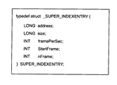
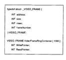
idxSサブチャンクD8は、idxHサブチャンクの属性情報を管理する。idxSサブチャンクD9は、SuperH_INDEXENTRY構造体の配列データを保持する。SuperH_INDEXENTRY構造体の例を図6に示す。変数addressは、本エントリが指すidxHインデックスのファイル上の開始アドレスを示す。変数sizeは、本エントリが指すidxHインデックスのサイズを示す。変数framePerSecは、本エントリが指すidxHインデックスの示す区間のフレームレートを示す。変数StartFrameは、本エントリが指すidxHインデックスの示す区間の先頭フレームのフレーム番号を示す。変数nFrameは、本エントリが指すidxHインデックスの示す区間のフレーム数を示す。例えば、図5に示す例は、idxHサブチャンクを2つ保持するので、idxSサブチャンクのデータ部は、図7に示すように、idxHサブチャンクD6,D7の属性情報をそれぞれ保持する2つのSUPER_INDEXENTRY構造体を保持する。
<動画シーケンス>
The idxS sub chunk D8 manages the attribute information of the idxH sub chunk. The idxS sub chunk D9 holds the array data of the SuperH_INDEXENTRY structure. An example of the SuperH_INDEXENTRY structure is shown in FIG. The variable address indicates the start address on the file of the idxH index pointed to by this entry. The variable size indicates the size of the idxH index pointed to by this entry. The variable framePerSec indicates the frame rate of the section indicated by the idxH index pointed to by this entry. The variable StartFrame indicates the frame number of the first frame in the section indicated by the idxH index pointed to by this entry. The variable nFrame indicates the number of frames in the section indicated by the idxH index pointed to by this entry. For example, since the example shown in FIG. 5 holds two idxH sub-chunks, the data part of the idxS sub-chunk, as shown in FIG. Hold the structure.
<Video sequence>
次に、図8乃至図10を参照して、本実施例の記録動作の説明をする。本実施例では、所定フレームレートで動画記録中に特定のキー操作、例えば、ターボボタンの押下により、その時点から一定期間までを当該所定フレームレートよりも高速なフレームレートで記録する。図8は、ターボボタンが押下された場合に起こる動画記録のフレームレートの時間変化を示す模式図である。 Next, the recording operation of the present embodiment will be described with reference to FIGS. In the present embodiment, a specific key operation, for example, pressing of a turbo button during recording of a moving image at a predetermined frame rate, records from that point to a certain period at a frame rate faster than the predetermined frame rate. FIG. 8 is a schematic diagram showing a temporal change in the frame rate of moving image recording that occurs when the turbo button is pressed.
ターボボタンが押下された時点(E1)から後の、FastPeriodにより秒数で指定される期間(E2)が、高速フレームレートで記録される期間であることを示している。本実施例における一連の動画撮影処理は、CPU38上で動作するリアルタイムOS上で動作する複数のタスクの協調動作によって実現される。
<タスク構成図>
The period (E2) specified by the number of seconds by FastPeriod after the time (E1) when the turbo button is pressed indicates that the period is recorded at the high frame rate. A series of moving image shooting processes in the present embodiment is realized by a cooperative operation of a plurality of tasks operating on a real-time OS operating on the
<Task configuration diagram>
図9は、本実施例における一連の動画撮影処理を行うソフトウエアのモジュール概略構成図である。 FIG. 9 is a schematic module configuration diagram of software for performing a series of moving image shooting processing in the present embodiment.
キードライバ100は、入力装置52上の不図示のスイッチ、ボタン等の操作部材を操作すると、キーイベントを発生する。動画撮影シーケンスタスク102は、キードライバ100からのキーイベントに応じて、動画撮影の開始、停止及び高速フレームレート記録期間の設定等を実行する。
When the
キャプチャコントローラ104は、動画撮影のために、CCD撮像素子16、A/Dコンバータ18、SSGユニット20、信号処理ユニット22、DMAコントローラ24、マイクロフォン30及びA/Dコンバータ32等の回路ブロックを制御する。この制御により、キャプチャコントローラ104は、フレーム単位のビデオデータ及び単位時間毎のオーディオデータからなる動画ストリームデータを生成する。
The
バッファ106はキャプチャコントローラ104が生成した動画ストリームデータとその管理情報を一時記憶する。具体的には、バッファ106は、フレーム単位のビデオデータを一時記憶するビデオバッファ、単位時間毎のオーディオデータを一時記憶するオーディオバッファ、オーディオチャンクにオーディオデータを書き込むために使用されるオーディオチャンクバッファ、並びに、インデックス情報を格納するidx1インデックスバッファ、idxHインデックスバッファ及びidxSインデックスバッファを具備する。DRAM26の一部がバッファ106として用いられる。また、キャプチャコントローラ104からバッファ106へのデータ転送には、DMAコントローラ24による信号処理装置22からシステムバス60を介したDRAM26へのDMA転送が使用される。
The
ストリーム生成タスク108は、キャプチャコントローラ104の動画ストリームデータ生成イベント及び動画ストリーム停止イベントを監視する。ストリーム書き込みタスク110は、記録媒体58上のファイルシステム112に対し、AVIファイルのオープン、クローズ、ファイルへのAVIヘッダの書き込み、ストリームデータの書き込み、及びインデックスの書き込みを実行する。
<動画撮影シーケンスタスク>
The
<Video sequence task>
次に、動画撮影シーケンスタスクの動作を説明する。図10は、動画撮影シーケンスタスクのフローチャートを示す。 Next, the operation of the moving image shooting sequence task will be described. FIG. 10 shows a flowchart of the moving image shooting sequence task.
動画撮影シーケンスタスク102は、アイドル状態(A)、動画撮影開始待ち状態(B)、動画撮影中状態(C)、ストリーム生成終了待ち状態(D)の4つの状態を持つ。 The moving image shooting sequence task 102 has four states: an idle state (A), a moving image shooting start waiting state (B), a moving image shooting in progress state (C), and a stream generation end waiting state (D).
アイドル状態(A)では、キードライバ100からSW1オンイベントを受け付けると(S10)、動画ファイルの生成場所である記録媒体58のストレージ空き容量を検査する(S11)。ストレージの空き容量が十分確保できたら、AF(オートフォーカス)処理を行う(S12)。AF処理が行われたら、動画撮影開始待ち状態(B)に遷移する。ここで、動画撮影開始待ち状態(B)は、SW2オンイベント(S13)とSW1オフイベント(S18)を受け付ける。
In the idle state (A), when the SW1 ON event is received from the key driver 100 (S10), the free storage capacity of the
動画撮影開始待ち状態(B)では、キードライバ100からSW2オンイベントを受け付けると(S13)、バッファ106を初期化し(S14)、ストリーム書込みタスク110に初期化要求イベントを送信する(S15)。ストリーム生成タスク108に初期化要求イベントを送信する(S16)。また、キャプチャコントローラ104に対して動画キャプチャ開始を指示し(S17)、動画撮影中状態(C)に遷移する。他方、動画撮影開始待ち状態(B)でSW1オフイベントを受け付けると(S18)、動画撮影を開始することなくアイドル状態(A)に遷移する。
In the moving image shooting start waiting state (B), when an SW2 on event is received from the key driver 100 (S13), the
動画撮影中状態(C)は、SW2オンイベント(S19)とターボボタン押下イベント(S24)を受け付ける。動画撮影中状態(C)で、キードライバ100からSW2オンイベントを受け付けると(S19)、キャプチャコントローラ104に動画キャプチャ停止を指示する(S20)。動画キャプチャ停止が完了したら、ストリーム生成終了待ち状態(D)に遷移する。
In the moving image shooting state (C), an SW2 on event (S19) and a turbo button press event (S24) are accepted. When the SW2 ON event is received from the
ストリーム生成終了待ち状態(D)は、ストリーム生成終了イベント(S21)のみを受け付ける。ストリーム生成終了待ち状態(D)で、ストリーム生成タスク108からストリーム生成終了イベントを受け付けると(S21)、ストリーム書込みタスク110にバッファフラッシュ指示イベントを送信し(S22)、ストリーム書込みタスク110にストリーム書込みタスク終了イベントを送信する(S23)。動画撮影シーケンスタスクはアイドル状態(A)に遷移し、一連の動画撮影シーケンスを終了する。
In the stream generation end waiting state (D), only the stream generation end event (S21) is accepted. When a stream generation end event is received from the
他方、動画撮影中状態(C)でターボボタン押下イベントを受け付けると(S24)、現在のフレーム番号を取得し、変数Cur_Frameにセットする(S25)。変数Fast_fps_beginに変数Cur_Frameの値をセットする(S26)。変数Fast_fps_endに、変数Cur_Frameと変数nFrameFastPeriodの和をセットする(S27)。以上の処理が終わったら、動画撮影中状態(C)に遷移する。 On the other hand, when a turbo button press event is received in the moving image shooting state (C) (S24), the current frame number is acquired and set in the variable Cur_Frame (S25). The value of the variable Cur_Frame is set in the variable Fast_fps_begin (S26). The variable Fast_fps_end is set to the sum of the variable Cur_Frame and the variable nFrameFastPeriod (S27). When the above processing is completed, the state transitions to the moving image shooting state (C).
ただし、変数nFrameFastPeriodの値は、変数CaptureFPSと変数FastPeriodの積である。変数CaptureFPSはキャプチャ時の1秒当たりのフレーム数であり、変数FastPeriodは高速フレームレートによる記録時間(秒)である。例えば、毎秒90フレームでキャプチャする場合で、2秒間の高速記録を行うときには、nFrameFastPeriod=90×2=180となる。
<ストリーム生成タスク>
However, the value of the variable nFrameFastPeriod is the product of the variable CaptureFPS and the variable FastPeriod. The variable CaptureFPS is the number of frames per second at the time of capture, and the variable FastPeriod is the recording time (seconds) at a high frame rate. For example, when capturing at 90 frames per second and performing high-speed recording for 2 seconds, nFrameFastPeriod = 90 × 2 = 180.
<Stream generation task>
図11は、ストリーム生成タスクのフローチャートである。ストリーム生成タスク108は、アイドル状態(A)とストリーム生成待ち状態(B)の2つの状態を持つ。
FIG. 11 is a flowchart of the stream generation task. The
アイドル状態(A)では、動画撮影シーケンスタスク102からのストリーム生成タスク初期化イベントを受け付ける(S30)。ストリーム生成タスク初期化イベントを受け付けると(S30)、ストリーム生成待ち状態(D)に遷移する。 In the idle state (A), a stream generation task initialization event is received from the moving image shooting sequence task 102 (S30). When a stream generation task initialization event is received (S30), the state transits to a stream generation wait state (D).
ストリーム生成待ち状態(D)は、ビデオフレームデータ生成完了イベント(S31)、オーディオデータ生成完了イベント(S32)及びストリーム停止イベント(S33)を受け付ける。ビデオフレームデータ生成完了イベント(S31)は、キャプチャコントローラ104により、ビデオフレームデータが1フレーム生成されるたびに発行される。オーディオデータ生成完了イベントは、キャプチャコントローラ104により、オーディオWAVEデータが所定単位時間分生成されるたびに発行される。
The stream generation wait state (D) receives a video frame data generation completion event (S31), an audio data generation completion event (S32), and a stream stop event (S33). The video frame data generation completion event (S31) is issued every time one frame of video frame data is generated by the
ストリーム生成待ち状態(D)でビデオフレームデータ生成完了イベントを受け付けると(S31)、ビデオバッファへの書込み処理を実行する(S32)。ストリーム書込みタスク110にストリーム生成イベントを送信し(S33)、ストリーム生成待ち状態(D)に遷移する。 When a video frame data generation completion event is received in the stream generation wait state (D) (S31), a write process to the video buffer is executed (S32). A stream generation event is transmitted to the stream writing task 110 (S33), and a transition to a stream generation waiting state (D) is made.
ストリーム生成待ち状態(D)でオーディオデータ生成完了イベントを受け付けると(S34)、オーディオバッファへの書込み処理を実行する(S35)。ストリーム書込みタスク110にストリーム生成イベントを送信し(S33)、ストリーム生成待ち状態(D)に遷移する。 When an audio data generation completion event is received in the stream generation wait state (D) (S34), a write process to the audio buffer is executed (S35). A stream generation event is transmitted to the stream writing task 110 (S33), and a transition to a stream generation waiting state (D) is made.
ストリーム生成待ち状態(D)でストリーム停止イベントを受け付けると(S36)、オーディオバッファへの書込み処理(S37)と、ビデオバッファへの書込み処理(S38)を実行する。そのあと、ストリーム書込みタスク110にストリーム生成終了イベントを送信し(S39)、アイドル状態(A)に遷移する。 When a stream stop event is received in the stream generation wait state (D) (S36), an audio buffer writing process (S37) and a video buffer writing process (S38) are executed. Thereafter, a stream generation end event is transmitted to the stream writing task 110 (S39), and the state transits to the idle state (A).
ビデオバッファ及びオーディオバッファのデータ転送は、キャプチャコントローラ104からのDMA転送により実現される。また、ビデオバッファへの書込み処理(S32、S38)及びオーディオバッファへの書込み処理(S34、S37)では、DMA転送された実データの属性情報を管理する処理も実行される。図12は、ビデオバッファに格納される各フレームの属性情報の一例を示す。
<ストリーム書込みタスク>
Data transfer of the video buffer and the audio buffer is realized by DMA transfer from the
<Stream write task>
図13は、ストリーム書き込みタスクのフローチャートを示す。ストリーム書込みタスク110は、アイドル状態(A)と書込み待ち状態(E)の2つの状態を持つ。
FIG. 13 shows a flowchart of the stream write task. The
アイドル状態(A)では、動画撮影シーケンスタスク102からのストリーム書込みタスク初期化イベントを受け付ける(S40)。ストリーム書込みタスク初期化イベントを受け付けると(S40)、ファイルシステム112に対して、新たに作成するAVIファイルを新規オープンする(S41)。新規ファイルがオープンされたら、AVIファイルのヘッダを生成し、当該ファイルに書き込む(S42)。チャンクヘッダの書き込み後、動画データ部に相当するmoviチャンクをオープンする(S43)。moviチャンクがオープンされたら、書込み待ち状態(E)に遷移する。 In the idle state (A), a stream writing task initialization event is received from the moving image shooting sequence task 102 (S40). When a stream write task initialization event is received (S40), a newly created AVI file is newly opened to the file system 112 (S41). When the new file is opened, an AVI file header is generated and written to the file (S42). After writing the chunk header, the movie chunk corresponding to the moving image data part is opened (S43). When the mobi chunk is opened, the state transits to the write wait state (E).
書込み待ち状態(E)では、ストリーム生成タスク108からのストリーム生成イベント(S44)、並びに、動画撮影シーケンスタスク102からのバッファフラッシュ指示イベント(S47)及びストリーム書込みタスク終了イベント(S49)の各処理を受け付ける。
In the write wait state (E), the stream generation event (S44) from the
書込み待ち状態(E)でストリーム生成イベントを受け付けると(S44)、ビデオバッファ上に溜まっているビデオフレーム数を取得し、書込み最小単位(フレーム数)と遡りバッファリング数の和と比較する(S45)。書込み最小単位とは、ファイルシステム112に一度に書き込む最小フレーム数であり、ファイルシステム112にストリーミングデータを効率的に書き込むために予め規定される。例えば、秒90フレームで書込みを1秒単位とする場合、書込み最小単位は、90(=1(秒)×90(フレーム))である。遡りバッファリング数とは、高速フレームレート期間を遅延して、数秒前までさかのぼって設定するためのバッファリングのフレーム数である。例えば、遡る期間を4秒と想定すると、高速フレームレートが秒90フレームの場合で、遡りバッファリング数は360(=4(秒)×90(フレーム))である。
When a stream generation event is received in the write wait state (E) (S44), the number of video frames accumulated in the video buffer is acquired and compared with the minimum write unit (number of frames) and the sum of the number of backward buffering (S45). ). The minimum writing unit is the minimum number of frames written to the
所定のフレームレートでの動画記録中にターボボタンが押された時点から一定期間を所定のフレームレートよりも高速なフレームレートで記録する場合には、遡りバッファリング数はゼロでよい。また、ターボボタンが押された場合で、その一定時間前から高速なフレームレートで記録するときには、遡りバッファリング数に遡る時間に相当する所定値を設定すればよい。 When recording at a frame rate faster than a predetermined frame rate for a certain period from when the turbo button is pressed during moving image recording at a predetermined frame rate, the retroactive buffering number may be zero. In addition, when the turbo button is pressed and recording is performed at a high frame rate from a certain time before, a predetermined value corresponding to the time going back to the number of retroactive buffering may be set.
ビデオバッファのフレーム数が書込最小単位と遡りバッファリング数の和以上の場合(S45)、バッファ106上のフレーム数から遡りバッファリング数を引いた値を書込み指定フレーム数としてセットし、バッファデータ書込み処理を実行する(S46)。バッファデータ書込み処理(S46)が完了したら、書込み待ち状態(E)に遷移する。バッファ106上のフレーム数が書込最小単位と遡りバッファリング数の和より小さい場合(S45)、書込みを実行せずに、書込み待ち状態(E)に遷移する。
When the number of frames in the video buffer is equal to or greater than the sum of the minimum writing unit and the number of retrogress buffering (S45), a value obtained by subtracting the retrogress buffering number from the number of frames on the
書込み待ち状態(E)で動画撮影シーケンスタスク102からのバッファフラッシュ指示イベントを受け付けると(S47)、バッファデータフラッシュ処理を実行する(S48)。バッファデータフラッシュ処理(S48)が完了すると、書込み待ち状態(E)に遷移する。 When a buffer flush instruction event is received from the moving image shooting sequence task 102 in the writing wait state (E) (S47), a buffer data flash process is executed (S48). When the buffer data flush process (S48) is completed, the state transits to the write wait state (E).
書込み待ち状態(E)で動画撮影シーケンスタスク102からのストリーム書込みタスク終了イベントを受け付けと(S49)、AVIファイルの動画データ部に相当するmoviチャンクのチャンクサイズを書き込み、チャンクをクローズする(S50)。インデックスidx1,idxSを書込むインデックス書き込み処理を実行する(S51)。S41でオープンしたAVIファイルのファイルハンドルをクローズする(S52)。以上の処理が完了したら、アイドル状態(A)に遷移して、動画ストリームファイルの一連の書込み処理を完了する。
<バッファデータ書込み処理>
In a state of waiting for writing (E), when a stream writing task end event is received from the moving image shooting sequence task 102 (S49), the chunk size of the movie chunk corresponding to the moving image data part of the AVI file is written, and the chunk is closed (S50). . An index writing process for writing the indexes idx1 and idxS is executed (S51). The file handle of the AVI file opened in S41 is closed (S52). When the above processing is completed, the state transits to the idle state (A), and a series of video stream file writing processing is completed.
<Buffer data write processing>
図14は、バッファデータ書き込み処理(S46)の詳細なフローチャートを示す。バッファデータ書込み処理は、呼び出されると、先ず、ループカウンタiをゼロにクリアする(S54)。フレーム書込み処理(S55)が実行され(S55)、ループカウンタiがインクリメントされる(S56)。フレーム書込み処理の詳細は後述する。書込み指定フレーム数がループカウンタiを越えたか否かが判定される(S57)。書込み指定フレーム数は、バッファデータ書込み処理が呼び出されるときに、引数として渡される。ループカウンタiが書込み指定フレーム数未満の間(S57)、フレーム書込み処理(S55)が繰り返され、ループカウンタiが書込み指定フレーム数以上になると(S57)、バッファデータ書込み処理を終了する。
<バッファデータフラッシュ処理>
FIG. 14 shows a detailed flowchart of the buffer data writing process (S46). When called, the buffer data writing process first clears the loop counter i to zero (S54). A frame writing process (S55) is executed (S55), and the loop counter i is incremented (S56). Details of the frame writing process will be described later. It is determined whether or not the number of write-designated frames exceeds the loop counter i (S57). The number of write-designated frames is passed as an argument when the buffer data write process is called. While the loop counter i is less than the number of write-designated frames (S57), the frame write process (S55) is repeated. When the loop counter i exceeds the number of write-designated frames (S57), the buffer data write process is terminated.
<Buffer data flush processing>
図15は、バッファデータフラッシュ処理(S48)の詳細なフローチャートを示す。バッファデータフラッシュ処理は、呼び出されると、バッファ106に残っているフレーム数をチェックする(S60)。残りフレーム数がゼロの場合(S60)、バッファデータフラッシュ処理を終了する。残りフレーム数がゼロで無い場合(S60)、1フレームのフレーム書込み処理を実行して(S61)、S60に戻る。このようにして、バッファ106に残る全フレームが、1フレームずつ掃き出される。
<フレーム書き込み処理>
FIG. 15 shows a detailed flowchart of the buffer data flush process (S48). When called, the buffer data flush process checks the number of frames remaining in the buffer 106 (S60). If the remaining number of frames is zero (S60), the buffer data flush process is terminated. When the number of remaining frames is not zero (S60), a frame writing process for one frame is executed (S61), and the process returns to S60. In this way, all frames remaining in the
<Frame writing process>
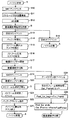
図16は、フレーム書き込み処理S55,S61の詳細なフローチャートを示す。 FIG. 16 shows a detailed flowchart of the frame writing processes S55 and S61.
バッファ106上に構成されるビデオバッファから1フレーム分のデータを取得する(S70)。取得したフレームのフレーム番号nFrameを、Fast_fps_begin及びFast_fps_endと比較し、nFrameが、Fast_fps_begin以上で且つFast_fps_end未満であるかどうかを判別する(S71)。ただし、Fast_fps_begin及びFast_fps_endは、ターボボタン押下イベント受信(S24)時にそのときのフレーム番号を基準にステップS26及びS27でそれぞれ設定される値である。すなわち、Fast_fps_begin及びFast_fps_endの値は、撮影者が通常のフレームレートよりも高速のフレームレートで記録したい特定期間を指定したことによって設定される。 One frame of data is acquired from the video buffer configured on the buffer 106 (S70). The frame number nFrame of the acquired frame is compared with Fast_fps_begin and Fast_fps_end, and it is determined whether nFrame is not less than Fast_fps_begin and less than Fast_fps_end (S71). However, Fast_fps_begin and Fast_fps_end are values set in steps S26 and S27, respectively, based on the frame number at the time of turbo button press event reception (S24). That is, the values of Fast_fps_begin and Fast_fps_end are set when the photographer specifies a specific period of time that is desired to be recorded at a frame rate higher than the normal frame rate.
nFrameの値がFast_fps_begin以上で、Fast_fps_end未満である場合(S71)、高速のフレームレートで記録したい特定期間であることを意味する。nFrameの値がFast_fps_begin未満、又は、Fast_fps_end以上の場合、高速のフレームレートで記録したい特定期間ではないことを意味し、低速(通常)のフレームレートで記録する期間であることを意味する。 When the value of nFrame is not less than Fast_fps_begin and less than Fast_fps_end (S71), it means that a specific period is desired to be recorded at a high frame rate. If the value of nFrame is less than Fast_fps_begin or greater than or equal to Fast_fps_end, it means that it is not a specific period for recording at a high frame rate, and it means a period for recording at a low (normal) frame rate.
低速で記録する期間の場合(S71)、取得したデータのフレーム番号nFrameをFPS_FAST/FPS_SLOWで割った余りを求め、その余りがゼロか否かを調べる(S72)。余りがゼロ以外の場合は、記録する必要の無いフレームであると判断して、このフレームに対する処理を終了する。余りがゼロの場合(S72)、記録する必要があるフレームと判断して、オーディオバッファから(1/FPS_SLOW)秒分のオーディオデータを取得する(S73)。 In the case of the recording period at low speed (S71), the remainder obtained by dividing the frame number nFrame of the acquired data by FPS_FAST / FPS_SLOW is obtained, and it is checked whether or not the remainder is zero (S72). If the remainder is not zero, it is determined that the frame does not need to be recorded, and the processing for this frame is terminated. If the remainder is zero (S72), it is determined that the frame needs to be recorded, and (1 / FPS_SLOW) seconds of audio data is acquired from the audio buffer (S73).
FPS_FASTは、単位時間(通常は1秒間)当たりの高速時のフレーム数を示し、FPS_SLOWとは、単位時間(通常は1秒間)当たりの低速(通常)時のフレーム数を示す。例えば、FPS_FAST=90で、FPS_SLOW=30である。 FPS_FAST indicates the number of frames at high speed per unit time (usually 1 second), and FPS_SLOW indicates the number of frames at low speed (normally) per unit time (usually 1 second). For example, FPS_FAST = 90 and FPS_SLOW = 30.
高速で記録する場合も(S71)、取得したデータのフレーム番号nFrameをFPS_FAST/FPS_SLOWで割った余りを求め、その余りがゼロか否かを調べる(S74)。余りが非ゼロの場合(S74)、高速時においてのみ記録するフレームであると判定して、(1/FPS_SLOW)秒分のダミーのオーディオデータ(例えば無音データ)を用意する(S76)。他方、余りがゼロの場合(S74)、高速時及び低速時のどちらでも記録する必要があるフレームと判断して、S75に遷移し、オーディオバッファから(1/FPS_SLOW)秒分のオーディオデータを取得する。但し、このオーディオデータは、オーディオチャンクバッファにセットされること無しに破棄される(S76)。これにより、高速時のフレームレートで記録された期間を再生するときにスローモーションで再生されると同時に、ビデオフレームとオーディオデータの同期がずれることを防ぐことを可能とする。 Also when recording at high speed (S71), the remainder obtained by dividing the frame number nFrame of the acquired data by FPS_FAST / FPS_SLOW is obtained, and it is checked whether or not the remainder is zero (S74). If the remainder is non-zero (S74), it is determined that the frame is a frame to be recorded only at high speed, and dummy audio data (for example, silence data) for (1 / FPS_SLOW) seconds is prepared (S76). On the other hand, if the remainder is zero (S74), it is determined that the frame needs to be recorded at both high speed and low speed, and the process proceeds to S75 to acquire audio data for (1 / FPS_SLOW) seconds from the audio buffer. To do. However, this audio data is discarded without being set in the audio chunk buffer (S76). This makes it possible to prevent the video frame and the audio data from being out of synchronization at the same time that the period recorded at the high frame rate is reproduced in slow motion.
ステップS76で用意されたダミーオーディオデータ、又は、ステップS73で取得されたオーディオデータをオーディオチャンクバッファにセットする(S77)。これにより、高速時のフレームレートで記録された期間を再生するときにスローモーションで再生されると同時にダミーオーディオ(無音)で音声が再生され、低速時のフレームレートで記録された期間を再生するときには通常スピードでビデオ及びオーディオが再生される動画ファイルを生成することが可能となる。 The dummy audio data prepared in step S76 or the audio data acquired in step S73 is set in the audio chunk buffer (S77). As a result, when the period recorded at the frame rate at the high speed is reproduced, the audio is reproduced at the same time as the dummy audio (silence) at the same time as the slow motion, and the period recorded at the frame rate at the low speed is reproduced. Sometimes it is possible to generate a video file in which video and audio are played at normal speed.
S78では、S70で取得したフレームデータを図4の画像データC9に相当する位置に書き込むことにより、ビデオチャンクをファイルに書き込む。図4のインデックスエントリC11に相当するビデオフレームデータ用のインデックスエントリのデータを生成して、インデックスバッファに書き込む(S79)。 In S78, the video chunk is written in the file by writing the frame data acquired in S70 in a position corresponding to the image data C9 in FIG. Video frame data index entry data corresponding to the index entry C11 of FIG. 4 is generated and written to the index buffer (S79).
オーディオデータが1秒分格納されたか否かを判別する(S80)オーディオデータが格納された場合(S80)、オーディオチャンクバッファに溜まった1秒分のオーディオデータを図4の音声データC4に相当する位置に書き込むことによってオーディオチャンクをファイルへ書き込む(S81)。図4のインデックスエントリC10に相当するオーディオデータ用のインデックスエントリのデータを生成して、インデックスバッファへ書き込む(S82)。 It is determined whether or not audio data has been stored for 1 second (S80). When audio data is stored (S80), the audio data for 1 second accumulated in the audio chunk buffer corresponds to the audio data C4 in FIG. The audio chunk is written to the file by writing to the position (S81). Audio entry index data corresponding to the index entry C10 of FIG. 4 is generated and written to the index buffer (S82).
以上の一連の処理により、フレーム書込み処理が完了する。 The frame writing process is completed by the series of processes described above.
図17は、以上の処理によるビデオバッファ及びオーディオバッファからAVIファイルへのデータ移動の模式図を示し、図18は、生成されるidx1インデックスの構成例を示す。 FIG. 17 shows a schematic diagram of data movement from the video buffer and audio buffer to the AVI file by the above processing, and FIG. 18 shows a configuration example of the generated idx1 index.
ビデオバッファには、高速フレームレートでキャプチャして生成したフレームデータが一旦格納される。図17に示す例では、フレームvideo10乃至video16が、高速フレームレートで記録されるべきフレームである。高速フレームレート期間以外の期間では、3フレームにつき2フレームが間引きされ、1フレームだけがAVIファイルに記録される。例えば、フレームvideo0,video3,video6,video9は、AVIファイルに格納されるが、それらのフレームの間に位置するフレームvideo1,video2,video4,video5,...は破棄される。これらの間引きの結果、残ったフレームのインデックスエントリが、図18に示すように、idx1インデックスバッファに保持される。高速フレームレート期間の各フレームvideo10乃至video18はすべて、AVIファイルに格納される。
The video buffer temporarily stores frame data generated by capturing at a high frame rate. In the example shown in FIG. 17, frames video10 to video16 are frames to be recorded at a high frame rate. In periods other than the high-speed frame rate period, two frames are thinned out for three frames, and only one frame is recorded in the AVI file. For example, the
オーディオバッファには、オーディオデータが随時格納される。オーディオバッファから随時、AVIファイルのオーディオチャンクのサイズ分のオーディオデータがオーディオチャンクバッファに読み出され、AVIファイルのオーディオチャンクに書き込まれる。ただし、高速フレームレート期間では、ダミーのオーディオデータdummy10乃至dummy16が、AVIファイルに格納される。
Audio data is stored in the audio buffer as needed. From time to time, audio data of the size of the audio chunk of the AVI file is read from the audio buffer to the audio chunk buffer and written to the audio chunk of the AVI file. However, during the high-speed frame rate period, dummy
図8では、所定操作(ターボボタンの押下)以後の一定期間を、高速フレームレートの記録期間とした。しかし、図19に示すように、所定操作(インパクトボタンの押下)に応じて、当該所定操作の時点を時間軸上の中心とする一定期間を高速フレームレートの記録期間としてもよい。例えば、インパクトボタンの押下前のFastPeriod/2秒間と、インパクトボタン押下後のFastPeriod/2秒間を併せた期間を、高速フレームレートの記録期間とする。 In FIG. 8, a certain period after a predetermined operation (pressing the turbo button) is defined as a high frame rate recording period. However, as shown in FIG. 19, in accordance with a predetermined operation (pressing the impact button), a certain period centered on the time axis of the predetermined operation may be set as the recording period of the high-speed frame rate. For example, a period in which FastPeriod / 2 seconds before the impact button is pressed and FastPeriod / 2 seconds after the impact button is pressed is defined as a high frame rate recording period.
この場合の撮影映像シーケンスタスクのフローチャートを図20に示す。図20は、主要部分で図10に示す撮影映像シーケンスタスクと同じであり、変更部分に符号aを付記してある。即ち、ターボボタンの代わりにインパクトボタンの押下イベントを受け付けるようにし(S24a)、ステップS26aでは、Fast_fps_beginにCur_Frame−nFrameFastPeriod/2をセットし、ステップS27aでは、Fast_fps_endに、Cur_Frame+nFrameFastPeriod/2をセットする。そして、図13に示すストリーム書込みタスクのステップS45では、遡りバッファリング数を、CaptureFPS×FastPeriod/2より大きな値に設定する必要がある。 A flowchart of the captured video sequence task in this case is shown in FIG. FIG. 20 is the same as the captured video sequence task shown in FIG. 10 in the main part, and the change part is denoted by reference symbol a. That is, an impact button pressing event is accepted instead of the turbo button (S24a), and in step S26a, Cur_Frame-nFrameFastPeriod / 2 is set in Fast_fps_begin, and in Step S27a, Fast_fps_end is set to Cur_Frame + nFrameFardPer. In step S45 of the stream writing task shown in FIG. 13, the retroactive buffering number needs to be set to a value larger than CaptureFPS × FastPeriod / 2.
更には、図21に示すように、所定操作(ロールバックボタンの押下)に応じて、当該所定操作から過去に遡る一定時間を高速フレームレートの記録期間としてもよい。 Furthermore, as shown in FIG. 21, according to a predetermined operation (pressing of the rollback button), a certain time that goes back to the past from the predetermined operation may be set as the recording period of the high-speed frame rate.
この場合の撮影映像シーケンスタスクのフローチャートを図22に示す。図20は、主要部分で図10に示す撮影映像シーケンスタスクと同じであり、変更部分に符号bを付記してある。即ち、ターボボタンの代わりにロールバックボタンの押下イベントを受け付けるようにし(S24b)、ステップS26bでは、Fast_fps_beginにCur_Frame−nFrameFastPeriodをセットし、ステップS27bでは、Fast_fps_endに、Cur_Frameをセットする。そして、図13に示すストリーム書込みタスクのステップS45では、遡りバッファリング数を、CaptureFPS×FastPeriodより大きな値に設定する必要がある。 A flowchart of the captured video sequence task in this case is shown in FIG. FIG. 20 is the same as the photographed video sequence task shown in FIG. 10 in the main part, and the changed part is denoted by reference symbol b. That is, a rollback button pressing event is accepted instead of the turbo button (S24b). In step S26b, Cur_Frame-nFrameFastPeriod is set in Fast_fps_begin, and in Step S27b, Cur_Frame is set in Fast_fps_end. In step S45 of the stream writing task shown in FIG. 13, the retroactive buffering number needs to be set to a value larger than CaptureFPS × FastPeriod.
動画の記録形式は、各画像を独立に圧縮符号化するMotion JPEG方式でもよいし、一連の画像を必要により相互に利用するMPEG方式でもよいし、その他の圧縮方式でもよい。 The recording format of the moving image may be a Motion JPEG method in which each image is independently compressed and encoded, an MPEG method in which a series of images are mutually used as necessary, or another compression method.
上記実施例では、記録媒体58として着脱自在なメモリカードを例示したが、デジタルカメラに内蔵される内部メモリを記録媒体58と想定しても良い。有線又は無線の通信プロトコルを用いて、通信制御42を介して接続可能な外部のストレージを記録媒体58とすることも可能である。
In the above embodiment, a removable memory card is illustrated as the
上記実施例では、高速フレームレートで撮影する期間を一定時間としたが、これに限るものではない。例えば、ビデオバッファの空き状況に応じて高速フレームレートで撮影する期間を増減させても良い。この場合、バッファの空きが所定量を下回った時点で高速フレームレートの期間を終了して、低速フレームレートの撮影に切り替えればよい。 In the above embodiment, the period for shooting at a high frame rate is set to a fixed time, but the present invention is not limited to this. For example, the period for shooting at a high frame rate may be increased or decreased according to the availability of the video buffer. In this case, the high-speed frame rate period may be terminated when the buffer free space falls below a predetermined amount, and switching to low-speed frame rate imaging may be performed.
上記実施例では、ダミーのオーディオデータに無音データを用いたが、実時間のオーディオデータを伸長して、スロー再生に同期するようなスローの音声に変換したものを、ダミーオーディオデータとして用いることも出来る。 In the above embodiment, silent data is used as dummy audio data, but real-time audio data is expanded and converted into slow sound that is synchronized with slow playback, and may be used as dummy audio data. I can do it.
図23は、フレーム書き込み処理S55,S61の別の詳細なフローチャートを示す。 FIG. 23 shows another detailed flowchart of the frame writing processes S55 and S61.
バッファ106上に構成されるビデオバッファから1フレーム分のデータを取得する(S170)。取得したフレームのフレーム番号nFrameを、Fast_fps_begin及びFast_fps_endと比較し、nFrameが、Fast_fps_begin以上で且つFast_fps_end以下であるかどうかを判別する(S171)。ただし、Fast_fps_begin及びFast_fps_endは、ターボボタン押下イベント受信(S24)時にそのときのフレーム番号を基準にステップS26及びS27でそれぞれ設定される値である。すなわち、Fast_fps_begin及びFast_fps_endの値は、撮影者が通常のフレームレートよりも高速のフレームレートで記録したい特定期間を指定したことによって設定される。 Data for one frame is acquired from the video buffer configured on the buffer 106 (S170). The frame number nFrame of the acquired frame is compared with Fast_fps_begin and Fast_fps_end, and it is determined whether nFrame is not less than Fast_fps_begin and not more than Fast_fps_end (S171). However, Fast_fps_begin and Fast_fps_end are values set in steps S26 and S27, respectively, based on the frame number at the time of turbo button press event reception (S24). That is, the values of Fast_fps_begin and Fast_fps_end are set when the photographer specifies a specific period of time that is desired to be recorded at a frame rate higher than the normal frame rate.
nFrameの値がFast_fps_begin以上で、Fast_fps_end以下である場合(S171)、高速のフレームレートで記録したい特定期間であることを意味する。nFrameの値がFast_fps_begin未満、又は、Fast_fps_endを越える場合、高速のフレームレートで記録したい特定期間ではないことを意味し、低速(通常)のフレームレートで記録する期間であることを意味する。 When the value of nFrame is greater than or equal to Fast_fps_begin and less than or equal to Fast_fps_end (S171), it means that a specific period is desired to be recorded at a high frame rate. If the value of nFrame is less than Fast_fps_begin or exceeds Fast_fps_end, it means that it is not a specific period for recording at a high frame rate, and it means a period for recording at a low (normal) frame rate.
低速で記録する期間の場合(S171)、取得したデータのフレーム番号nFrameをFPS_FAST/FPS_SLOWで割った余りを求め、その余りがゼロか否かを調べる(S172)。余りがゼロ以外の場合(S172)は、記録する必要の無いフレームであると判断して、このフレームに対する処理を終了する。余りがゼロの場合(S172)、記録する必要があるフレームと判断して、S175に遷移する。 In the case of the recording period at low speed (S171), the remainder obtained by dividing the frame number nFrame of the acquired data by FPS_FAST / FPS_SLOW is obtained, and it is checked whether or not the remainder is zero (S172). If the remainder is other than zero (S172), it is determined that the frame does not need to be recorded, and the processing for this frame is terminated. If the remainder is zero (S172), it is determined that the frame needs to be recorded, and the process proceeds to S175.
FPS_FASTは、単位時間(通常は1秒間)当たりの高速時のフレーム数を示し、FPS_SLOWとは、単位時間(通常は1秒間)当たりの低速(通常)時のフレーム数を示す。例えば、FPS_FAST=90で、FPS_SLOW=30である。 FPS_FAST indicates the number of frames at high speed per unit time (usually 1 second), and FPS_SLOW indicates the number of frames at low speed (normally) per unit time (usually 1 second). For example, FPS_FAST = 90 and FPS_SLOW = 30.
高速で記録する場合、即ち、nFrameの値がFast_fps_begin以上で、Fast_fps_end以下である場合(S171)、高速フレームレート区間のためのインデックスであるidxHインデックスバッファにインデックスエントリを生成する(S173)。取得したデータのフレーム番号nFrameをFPS_FAST/FPS_SLOWで割った余りを求め、その余りがゼロか否かを調べる(S174)。余りがゼロの場合(S74)、高速時及び低速時のどちらでも記録する必要があるフレームと判断して、S182に遷移する。余りがゼロ以外の場合(S174)、高速時においてのみ記録すべきフレームであると判断してS175に遷移する。 When recording at high speed, that is, when the value of nFrame is not less than Fast_fps_begin and not more than Fast_fps_end (S171), an index entry is generated in the idxH index buffer that is an index for the high-speed frame rate interval (S173). A remainder obtained by dividing the frame number nFrame of the acquired data by FPS_FAST / FPS_SLOW is obtained, and it is checked whether or not the remainder is zero (S174). If the remainder is zero (S74), it is determined that the frame needs to be recorded at both high speed and low speed, and the process proceeds to S182. If the remainder is other than zero (S174), it is determined that the frame should be recorded only at high speed, and the process proceeds to S175.
S175では、S170で取得したフレームデータを図4の画像データC9に相当する位置に書き込むことにより、ビデオチャンクをファイルに書き込む。図4のインデックスエントリC11に相当するビデオフレームデータ用のインデックスエントリのデータを生成して、idx1インデックスバッファに書き込む(S176)。オーディオバッファから(1/FPS_SLOW)秒分のオーディオデータ(例えば、1/30秒分)を取得する(S177)。取得したオーディオデータをオーディオチャンクバッファにセットする(S178)。 In S175, the video chunk is written in the file by writing the frame data acquired in S170 in a position corresponding to the image data C9 in FIG. The index entry data for video frame data corresponding to the index entry C11 of FIG. 4 is generated and written to the idx1 index buffer (S176). Audio data for (1 / FPS_SLOW) seconds (for example, 1/30 seconds) is acquired from the audio buffer (S177). The acquired audio data is set in the audio chunk buffer (S178).
オーディオデータが1秒分格納されたか否かを判別する(S179)。オーディオデータが1秒分以上、格納されている場合(S179)、オーディオチャンクバッファに溜まった1秒分のオーディオデータを図4の音声データC4に相当する位置に書き込むことによってオーディオチャンクをファイルに書き込む(S180)。図4のidx1インデックスのインデックスエントリC10に相当するオーディオデータ用のインデックスエントリのデータを生成して、idx1インデックスバッファへ書き込む(S181)。オーディオデータが1秒分以上、格納されていない場合(S179)、ステップS180,S181を迂回する。 It is determined whether or not audio data has been stored for one second (S179). When the audio data is stored for 1 second or more (S179), the audio chunk is written in the file by writing the audio data for 1 second accumulated in the audio chunk buffer in the position corresponding to the audio data C4 in FIG. (S180). Audio index entry data corresponding to the index entry C10 of the idx1 index in FIG. 4 is generated and written to the idx1 index buffer (S181). If the audio data has not been stored for 1 second or longer (S179), steps S180 and S181 are bypassed.
nFrameとFast_fps_endの値が等しいか否かを判別する(S183)。nFrameとFast_fps_endが等しければ(S183)、高速フレームレート撮影区間が終了したと判断し、idxHインデックスバッファの内容を図5のidxHインデックスにD5,D6相当するファイルの位置に書き込む(S184)。idxHのインデックスであるidxSのインデックスバッファにエントリを生成する(S85)。 It is determined whether nFrame and Fast_fps_end are equal to each other (S183). If nFrame and Fast_fps_end are equal (S183), it is determined that the high-speed frame rate imaging period has ended, and the contents of the idxH index buffer are written in the idxH index of FIG. An entry is generated in the index buffer of idxS that is the index of idxH (S85).
以上、説明した一連の処理によって、フレーム書き込み処理が完了する。 The frame writing process is completed by the series of processes described above.
図24は、以上の処理によるビデオバッファ及びオーディオバッファからAVIファイルへのデータ移動の模式図を示し、図25は、生成されるidx1インデックスの構成例を示す。 FIG. 24 shows a schematic diagram of data movement from the video buffer and the audio buffer to the AVI file by the above processing, and FIG. 25 shows a configuration example of the generated idx1 index.
ビデオバッファには、高速フレームレートでキャプチャして生成したフレームデータが一旦格納される。図24に示す例では、フレームvideo10乃至video18が、高速フレームレートで記録されるべきフレームである。高速フレームレート期間以外の期間では、3フレームにつき2フレームが間引きされ、1フレームだけがAVIファイルに記録される。例えば、フレームvideo0,video3,video6,video9は、AVIファイルに格納されるが、それらのフレームの間に位置するフレームvideo1,video2,video4,video5,...は破棄される。これらの間引きの結果、残ったフレームのインデックスエントリが、図25に示すように、idx1インデックスバッファに保持される。高速フレームレート期間の各フレームvideo10乃至video18はすべて、AVIファイルに格納される。
The video buffer temporarily stores frame data generated by capturing at a high frame rate. In the example shown in FIG. 24, frames video10 to video18 are frames to be recorded at a high frame rate. In periods other than the high-speed frame rate period, two frames are thinned out for three frames, and only one frame is recorded in the AVI file. For example, the
ひとつの高速フレームレート期間の各フレームvideo10乃至video18のインデックスエントリがidxHインデックスバッファに保持される。高速フレームレート区間の記録が終わったら、AVIファイル上の直後のファイル位置に、idxHインデックスバッファの内容がidxHインデックスとして記録される。idxHのエントリはidxSインデックスバッファに保持される。
<インデックス書き込み処理>
An index entry of each frame video10 to video18 in one high-speed frame rate period is held in the idxH index buffer. When the recording of the high-speed frame rate section is finished, the contents of the idxH index buffer are recorded as the idxH index at the file position immediately after the AVI file. The idxH entry is held in the idxS index buffer.
<Index writing process>
図26は、インデックス書込み処理のフローチャートを示す。idx1インデックスバッファのデータをファイルに書き込み(S90)、idxSインデックスバッファのデータをファイルに書き込む(S91)。idx1及びidxHのインデックスデータは、図5に示すファイルのD7、D8にそれぞれ対応する位置に書込まれる。
<再生時の表示>
FIG. 26 shows a flowchart of the index writing process. The data of the idx1 index buffer is written to the file (S90), and the data of the idxS index buffer is written to the file (S91). The index data of idx1 and idxH are written at positions corresponding to D7 and D8 of the file shown in FIG.
<Display during playback>
図27は、再生モードで起動した時の一覧表示である。図28は、再生画面例である。図27では、9つの画像オブジェクトG1〜G9のサムネイル画像が表示されている。その中で、オブジェクトG2〜G4のサムネイル画像の左側に表示されるパーフォレーションマークは、動画ファイルであることを示している。さらに、オブジェクトG2、G3サムネイル画像には、複数のフレームレートで記録されていることを示す“Dual Speed”アイコンが付与されている。 FIG. 27 is a list display when starting in the reproduction mode. FIG. 28 shows an example of a playback screen. In FIG. 27, thumbnail images of nine image objects G1 to G9 are displayed. Among them, the perforation mark displayed on the left side of the thumbnail images of the objects G2 to G4 indicates that it is a moving image file. Further, the “Dual Speed” icon indicating that the objects G2 and G3 thumbnail images are recorded at a plurality of frame rates is given.
図27に示す画面を表示した状態で、ユーザは十字キー(不図示)等を用いて、任意のオブジェクトを選択して再生を指示することができる。例えば、オブジェクトG2又はG4を選択し、エンターキー(不図示)を押下すると、図28に示すようなオブジェクトG2又はG4の再生画面が表示される。 In a state where the screen shown in FIG. 27 is displayed, the user can select an arbitrary object and instruct reproduction using an arrow key (not shown) or the like. For example, when the object G2 or G4 is selected and an enter key (not shown) is pressed, a reproduction screen of the object G2 or G4 as shown in FIG. 28 is displayed.
再生画面H1には、種々の操作ボタンH2〜H10と情報を表示するアイコンH11〜H15がGUI(Graphical User Interface)上に表示される。 Various operation buttons H2 to H10 and icons H11 to H15 for displaying information are displayed on a GUI (Graphical User Interface) on the reproduction screen H1.
操作ボタンH2〜H10は、十字キー等で選択される。停止状態で再生ボタンH2を押すことにより動画再生が開始される。ジャンプボタンH3、H4は、それぞれ先頭・末尾へのジャンプを指示する。高速再生ジャンプボタンH5、H6は、動画ファイル内に複数存在する高速フレームレート区間へのジャンプを指示する。コマ送りボタンH7、H8は、前後へのコマ送りを指示する。スロー再生ボタンH9は、動画のスロー再生を指示する。再生スピード選択ボタンH10は、スロー再生ボタンH9が押下されて、スロー再生状態になった場合に、スロー再生の再生スピードを選択するのに使用される。すなわち、再生スピード選択ボタンH10は、スロー再生中に十字キーを左右に選択することにより、スロー再生スピードの増減を指示する。 The operation buttons H2 to H10 are selected with a cross key or the like. The moving image reproduction is started by pressing the reproduction button H2 in the stop state. The jump buttons H3 and H4 respectively instruct to jump to the head and tail. The high-speed playback jump buttons H5 and H6 instruct to jump to a plurality of high-speed frame rate sections existing in the moving image file. The frame advance buttons H7 and H8 instruct forward and backward frame advance. The slow playback button H9 instructs the slow playback of a moving image. The playback speed selection button H10 is used to select a playback speed for slow playback when the slow playback button H9 is pressed to enter a slow playback state. That is, the playback speed selection button H10 instructs to increase or decrease the slow playback speed by selecting the cross key to the left or right during slow playback.
デュアルスピードアイコンH11は、現在再生中の動画ファイルが複数のフレームレート区間を含む動画ファイルであることを表す。プログレスバーH12は、現在の動画再生位置を表示する。プログレスバーH12の斜線部は、高速フレームレート区間H13、H14である。すなわち、現在再生中の動画ファイルにおける高速フレームレート区間の位置を示す。idxSに格納されているSUPER_INDEXENTRY(図6参照)の各エントリのStartFrameとnFrameの値を参照することで、高速フレームレート区間の開始フレーム及びフレーム数を取得できる。これらの情報から、ファイルにおける全動画フレームのなかでの高速フレームレート区間H13、H14の相対位置が求まる。 The dual speed icon H11 represents that the moving image file currently being reproduced is a moving image file including a plurality of frame rate sections. The progress bar H12 displays the current moving image playback position. The hatched portions of the progress bar H12 are high-speed frame rate sections H13 and H14. That is, it indicates the position of the high-speed frame rate section in the moving image file currently being reproduced. By referring to the values of StartFrame and nFrame of each entry of SUPER_INDEXENTRY (see FIG. 6) stored in idxS, the start frame and the number of frames in the high-speed frame rate interval can be acquired. From these pieces of information, the relative positions of the high-speed frame rate sections H13 and H14 in all moving image frames in the file are obtained.
高速フレームレート区間H13、H14の先頭位置は、idxSに格納されているSUPER_INDEXENTRYの各エントリのaddress値を参照して、高速フレームレート区間を示すidxHインデックスを参照し、当該idxHインデックスの先頭フレームのアドレスを取得することにより、決定できる。 The start positions of the high-speed frame rate intervals H13 and H14 are referred to the address value of each entry of SUPER_INDEXENTRY stored in idxS, refer to the idxH index indicating the high-speed frame rate interval, and the address of the start frame of the idxH index Can be determined by obtaining
このようにして、容易に高速フレームレート区間のみを選択して再生することができ、検索の手間を省くことができる。また、高速フレームレート区間H13、H14を備えたので、使用者にフレームレートの切り替え期間を表示することでき、使用者が高速なフレームレートで記録された期間を容易に選択することができる。 In this way, it is possible to easily select and reproduce only the high-speed frame rate interval, and to save the search effort. Also, since the high-speed frame rate sections H13 and H14 are provided, the frame rate switching period can be displayed to the user, and the user can easily select the period recorded at the high frame rate.
10 デジタルカメラ
12 レンズユニット
14 絞り・シャッタ機構
16 CCD撮像素子
18 A/Dコンバータ
20 SSGユニット
22 信号処理ユニット
24 DMAコントローラ
26 DRAM
28 フラッシュROM
30 マイクロフォン
32 A/Dコンバータ
34 絞り制御
36 レンズ制御
38 CPU
40 表示制御
42 通信制御
44 記録媒体制御
46 電池
48 電源制御
50 DC/DCコンバータ
52 入力装置
54 表示装置
56 通信コネクタ
58 記録媒体
60 システムバス
100 キードライバ
102 動画撮影シーケンスタスク
104 キャプチャコントローラ
106 バッファ
108 ストリーム生成タスク
110 ストリーム書込みタスク
112 ファイルシステム
DESCRIPTION OF
28 Flash ROM
30 Microphone 32 A /
40
Claims (8)
マイクにより得られた音声信号を入力する音声入力手段と、
前記画像入力手段により入力された画像信号を用いて、第1のフレームレートの第1の動画像信号または、前記第1のフレームレートよりも高い第2のフレームレートの第2の動画像信号を生成するとともに、生成した前記第1の動画像信号または前記第2の動画像信号と、音声信号とからなるストリームを生成するストリーム生成手段と、
前記ストリーム生成手段により生成されたストリームを記録媒体に記録する記録手段と、
前記第2の動画像信号の生成を指示する指示手段
とを備え、
前記ストリーム生成手段は、前記第1の動画像信号と前記音声入力手段により入力された前記音声信号とからなる第1のストリームを生成しているときに、前記指示手段により指示がされたことに応じて、前記第1のストリームに代えて、前記第2の動画像信号と無音を示す音声信号とからなる第2のストリームを生成することを特徴とする記録装置。 An image input means for inputting images signal,
An audio input means for inputting an audio signal obtained by a microphone ;
Using images signal inputted by said image input means, first moving image signal in a first frame rate or a second moving image signal of the second higher frame rate than the first frame rate to generate a, and generated the first moving image signal or the second moving image signal, and the stream generation unit that forms the raw Luz stream-such from an audio signal,
Recording means for recording the stream generated by the stream generation means on a recording medium;
Instruction means for instructing generation of the second moving image signal ,
The stream generating means, when generating a first stream consisting of the inputted speech signal by the first moving image signal and said audio input means, that instruction has been by the instruction means Accordingly, the recording apparatus is characterized in that, instead of the first stream, a second stream including the second moving image signal and an audio signal indicating silence is generated .
前記第1のインデックス情報と前記第2のインデックス情報とに基づいて、前記動画ファイルにおける前記第1の動画像信号の期間と前記第2の動画信号の期間を区別して表示装置に表示することを特徴とする再生装置。 A playback device for playing back a moving image file recorded by the recording device according to claim 7 ,
Based on the first index information and the second index information, a period of the first moving image signal and a period of the second moving image signal in the moving image file are distinguished and displayed on the display device. A playback device.
Priority Applications (3)
| Application Number | Priority Date | Filing Date | Title |
|---|---|---|---|
| JP2005176872A JP4537266B2 (en) | 2005-06-16 | 2005-06-16 | Recording apparatus and reproducing apparatus |
| US11/423,211 US7920775B2 (en) | 2005-06-16 | 2006-06-09 | Recording apparatus |
| US13/032,702 US8938150B2 (en) | 2005-06-16 | 2011-02-23 | Recording apparatus |
Applications Claiming Priority (1)
| Application Number | Priority Date | Filing Date | Title |
|---|---|---|---|
| JP2005176872A JP4537266B2 (en) | 2005-06-16 | 2005-06-16 | Recording apparatus and reproducing apparatus |
Publications (3)
| Publication Number | Publication Date |
|---|---|
| JP2006352581A JP2006352581A (en) | 2006-12-28 |
| JP2006352581A5 JP2006352581A5 (en) | 2008-07-24 |
| JP4537266B2 true JP4537266B2 (en) | 2010-09-01 |
Family
ID=37647928
Family Applications (1)
| Application Number | Title | Priority Date | Filing Date |
|---|---|---|---|
| JP2005176872A Active JP4537266B2 (en) | 2005-06-16 | 2005-06-16 | Recording apparatus and reproducing apparatus |
Country Status (2)
| Country | Link |
|---|---|
| US (2) | US7920775B2 (en) |
| JP (1) | JP4537266B2 (en) |
Families Citing this family (18)
| Publication number | Priority date | Publication date | Assignee | Title |
|---|---|---|---|---|
| JP4770581B2 (en) * | 2006-05-17 | 2011-09-14 | ソニー株式会社 | Moving image data processing device, stream generation device, imaging device, and moving image data processing method |
| US8511901B2 (en) * | 2007-02-06 | 2013-08-20 | Canon Kabushiki Kaisha | Image recording apparatus and method |
| JP4810485B2 (en) * | 2007-03-29 | 2011-11-09 | キヤノン株式会社 | Image processing apparatus, image processing method, and computer program |
| JP5018332B2 (en) | 2007-08-17 | 2012-09-05 | ソニー株式会社 | Image processing apparatus, imaging apparatus, image processing method, and program |
| US8077222B2 (en) * | 2007-11-06 | 2011-12-13 | Canon Kabushiki Kaisha | Image processing apparatus to transmit moving image data |
| EP2249557B1 (en) * | 2008-02-20 | 2016-10-12 | Ntt Docomo, Inc. | Imaging device, imaging method, and program |
| JP2010087778A (en) * | 2008-09-30 | 2010-04-15 | Casio Computer Co Ltd | Imaging apparatus, variable speed imaging method, and program |
| US20120044327A1 (en) * | 2009-05-07 | 2012-02-23 | Shinichi Horita | Device for acquiring stereo image |
| US8736702B2 (en) * | 2009-12-22 | 2014-05-27 | Samsung Electronics Co., Ltd. | Apparatus and method of calculating a shooting frequency based on the obtained sound information |
| JP2011139306A (en) * | 2009-12-28 | 2011-07-14 | Sanyo Electric Co Ltd | Imaging device, and reproduction device |
| JP2011193424A (en) * | 2010-02-16 | 2011-09-29 | Casio Computer Co Ltd | Imaging apparatus and method, and program |
| JP5902928B2 (en) * | 2011-11-25 | 2016-04-13 | キヤノン株式会社 | Playback device, control method thereof, and program |
| JP2014027560A (en) * | 2012-07-27 | 2014-02-06 | Xacti Corp | Image processor |
| JP6012384B2 (en) * | 2012-10-04 | 2016-10-25 | キヤノン株式会社 | Video playback device, display control method, program, and storage medium |
| JP2015122731A (en) * | 2013-11-19 | 2015-07-02 | パナソニックIpマネジメント株式会社 | Video replay device and video replay method |
| JP2015186235A (en) * | 2014-03-26 | 2015-10-22 | ソニー株式会社 | Image sensor and electronic apparatus |
| KR102449872B1 (en) | 2015-12-18 | 2022-09-30 | 삼성전자주식회사 | Photographing apparatus and method for controlling the same |
| US11095838B2 (en) * | 2017-01-25 | 2021-08-17 | Samsung Electronics Co., Ltd | Electronic device and method for capturing image in electronic device |
Citations (3)
| Publication number | Priority date | Publication date | Assignee | Title |
|---|---|---|---|---|
| JP2004129217A (en) * | 2002-08-01 | 2004-04-22 | Canon Inc | Device and method for image processing, computer program, and computer readable storage medium |
| JP2004221999A (en) * | 2003-01-15 | 2004-08-05 | Canon Inc | Image processing method |
| JP2005136754A (en) * | 2003-10-31 | 2005-05-26 | Matsushita Electric Ind Co Ltd | Imaging apparatus |
Family Cites Families (10)
| Publication number | Priority date | Publication date | Assignee | Title |
|---|---|---|---|---|
| JP3129599B2 (en) | 1994-04-26 | 2001-01-31 | キヤノン株式会社 | Video imaging system |
| US5640202A (en) * | 1994-04-26 | 1997-06-17 | Canon Kabushiki Kaisha | Imaging system which changes the frame rate of the image signal |
| US7110025B1 (en) * | 1997-05-28 | 2006-09-19 | Eastman Kodak Company | Digital camera for capturing a sequence of full and reduced resolution digital images and storing motion and still digital image data |
| US6192188B1 (en) * | 1997-10-20 | 2001-02-20 | Lsi Logic Corporation | Programmable audio/video encoding system capable of downloading compression software from DVD disk |
| JP3276596B2 (en) * | 1997-11-04 | 2002-04-22 | 松下電器産業株式会社 | Video editing device |
| CN1292409C (en) * | 1998-03-13 | 2006-12-27 | 松下电器产业株式会社 | Information recording method on optical disk and reproducing device and method |
| JP2003219412A (en) * | 2002-01-22 | 2003-07-31 | Fuji Photo Film Co Ltd | Image recorder for on-vehicle camera |
| JP4228271B2 (en) * | 2002-07-09 | 2009-02-25 | 日本電気株式会社 | Video data compression apparatus and video data compression method |
| JP2005027159A (en) * | 2003-07-04 | 2005-01-27 | Canon Inc | Recording apparatus and method therefor |
| JP2005086499A (en) * | 2003-09-09 | 2005-03-31 | Minolta Co Ltd | Imaging apparatus |
-
2005
- 2005-06-16 JP JP2005176872A patent/JP4537266B2/en active Active
-
2006
- 2006-06-09 US US11/423,211 patent/US7920775B2/en not_active Expired - Fee Related
-
2011
- 2011-02-23 US US13/032,702 patent/US8938150B2/en active Active
Patent Citations (3)
| Publication number | Priority date | Publication date | Assignee | Title |
|---|---|---|---|---|
| JP2004129217A (en) * | 2002-08-01 | 2004-04-22 | Canon Inc | Device and method for image processing, computer program, and computer readable storage medium |
| JP2004221999A (en) * | 2003-01-15 | 2004-08-05 | Canon Inc | Image processing method |
| JP2005136754A (en) * | 2003-10-31 | 2005-05-26 | Matsushita Electric Ind Co Ltd | Imaging apparatus |
Also Published As
| Publication number | Publication date |
|---|---|
| JP2006352581A (en) | 2006-12-28 |
| US8938150B2 (en) | 2015-01-20 |
| US20070013808A1 (en) | 2007-01-18 |
| US7920775B2 (en) | 2011-04-05 |
| US20110142412A1 (en) | 2011-06-16 |
Similar Documents
| Publication | Publication Date | Title |
|---|---|---|
| JP4537266B2 (en) | Recording apparatus and reproducing apparatus | |
| JPWO2006028172A1 (en) | Recording apparatus and method, reproducing apparatus and method, and program | |
| JP2007221681A (en) | Image reproducing apparatus, music processing program, and image reproducing program | |
| JP2012161048A (en) | Imaging apparatus | |
| JP2009225361A (en) | Recording device and recording method, and editing device and editing method | |
| JP4665793B2 (en) | Moving image file generation program and electronic camera | |
| JP5818599B2 (en) | Movie recording device | |
| JP2012156587A (en) | Video recording device | |
| JP5683301B2 (en) | Image recording device | |
| JP2005260749A (en) | Electronic camera and control program thereof | |
| JP5076457B2 (en) | Video signal processing apparatus and video signal processing method | |
| JP4761544B2 (en) | Reproducing apparatus and control method thereof | |
| JP5713701B2 (en) | Movie recording device | |
| JP4698961B2 (en) | Electronic camera and electronic camera control program | |
| JP2006080723A (en) | Recording device and recording method, reproduction device and reproduction method, and program | |
| US8379109B2 (en) | Image processing apparatus | |
| JP5773855B2 (en) | Image processing device | |
| JP2009055618A (en) | Electronic camera and control program of electronic camera | |
| JP2011146847A (en) | Image reproduction controller, image reproduction control method, and imaging device | |
| JP5645096B2 (en) | Movie processing apparatus, movie playback method, movie recording method, and program | |
| JP2010183370A (en) | Image reproducing apparatus | |
| JP6463967B2 (en) | Imaging apparatus and control method thereof | |
| JP4298583B2 (en) | Imaging device and mobile phone | |
| JP5889459B2 (en) | Recording device | |
| JP5383073B2 (en) | Editing apparatus and editing method |
Legal Events
| Date | Code | Title | Description |
|---|---|---|---|
| A521 | Request for written amendment filed |
Free format text: JAPANESE INTERMEDIATE CODE: A523 Effective date: 20080611 |
|
| A621 | Written request for application examination |
Free format text: JAPANESE INTERMEDIATE CODE: A621 Effective date: 20080611 |
|
| A977 | Report on retrieval |
Free format text: JAPANESE INTERMEDIATE CODE: A971007 Effective date: 20091228 |
|
| A131 | Notification of reasons for refusal |
Free format text: JAPANESE INTERMEDIATE CODE: A131 Effective date: 20100105 |
|
| A521 | Request for written amendment filed |
Free format text: JAPANESE INTERMEDIATE CODE: A523 Effective date: 20100122 |
|
| TRDD | Decision of grant or rejection written | ||
| A01 | Written decision to grant a patent or to grant a registration (utility model) |
Free format text: JAPANESE INTERMEDIATE CODE: A01 Effective date: 20100615 |
|
| A01 | Written decision to grant a patent or to grant a registration (utility model) |
Free format text: JAPANESE INTERMEDIATE CODE: A01 |
|
| A61 | First payment of annual fees (during grant procedure) |
Free format text: JAPANESE INTERMEDIATE CODE: A61 Effective date: 20100617 |
|
| FPAY | Renewal fee payment (event date is renewal date of database) |
Free format text: PAYMENT UNTIL: 20130625 Year of fee payment: 3 |
|
| R150 | Certificate of patent or registration of utility model |
Ref document number: 4537266 Country of ref document: JP Free format text: JAPANESE INTERMEDIATE CODE: R150 Free format text: JAPANESE INTERMEDIATE CODE: R150 |
|
| RD03 | Notification of appointment of power of attorney |
Free format text: JAPANESE INTERMEDIATE CODE: R3D03 |