JP4533229B2 - Rice transplanter with fertilizer application - Google Patents
Rice transplanter with fertilizer application Download PDFInfo
- Publication number
- JP4533229B2 JP4533229B2 JP2005129547A JP2005129547A JP4533229B2 JP 4533229 B2 JP4533229 B2 JP 4533229B2 JP 2005129547 A JP2005129547 A JP 2005129547A JP 2005129547 A JP2005129547 A JP 2005129547A JP 4533229 B2 JP4533229 B2 JP 4533229B2
- Authority
- JP
- Japan
- Prior art keywords
- clutch
- feeding
- fertilizer
- planting
- rice transplanter
- Prior art date
- Legal status (The legal status is an assumption and is not a legal conclusion. Google has not performed a legal analysis and makes no representation as to the accuracy of the status listed.)
- Active
Links
Images


Description
本発明は、施肥装置に全条の繰出し機構のうちの一部を休止させる複数の繰出しクラッチを装備してある施肥装置付き田植機に関する。 [Technical Field] The present invention relates to a rice transplanter with a fertilizer applicator equipped with a plurality of pay-out clutches that cause the fertilizer applicator to pause a part of the entire pay-out mechanism.
田植機においては、畦際に沿った最後の植付け行程を全条植えで行うために、その前の植付け行程において苗植付け装置に備えられた畦際クラッチの一部を切って、一部の植付けを休止して少数条の植付けを行うことができるように構成されており、施肥装置付き田植機においては、植付けが休止された条の施肥を休止するために施肥装置に全条の繰出し機構のうちの一部を休止させる複数の繰出しクラッチを装備してある。 In the rice transplanter, in order to carry out the final planting process along the shoreline by full-row planting, a part of the heel clutch provided in the seedling planting device was cut off in the previous planting process, and a part of planting was performed. In a rice transplanter with a fertilizer device, the fertilizer is equipped with a full-row feed mechanism in order to stop the fertilization of the strip for which planting has been suspended. Equipped with a plurality of pay-out clutches that pause some of them.
少数条植えを行うに際して、運転作業者が簡単な選択操作で所望の少数条植え状態を現出できるように、手元のスイッチ操作で電動モータなどのアクチュエータを作動させ、アクチュエータに連動連結した繰出しクラッチおよび畦際クラッチを入り切り操作するよう構成したものが提案されている(例えば、特許文献1参照)。
上記提案構造における繰出しクラッチの操作構造としては、左右に並列配備された繰出しクラッチ群の端部近くに、アクチュエータによって作動されるクラッチ操作ユニットを設け、このクラッチ操作ユニットから導出された複数の操作ワイヤが各繰出しクラッチの操作部に連動連結した構造が採用されており、クラッチ操作ユニットと各繰出しクラッチとのワイヤ連係構造に多くの部品を必要としてコスト高の一因となるものであった。また、操作ワイヤは余り小さい曲率では屈曲できないので余裕をもったワイヤ引き回しが必要であり、このために、繰出しクラッチ群の周辺にワイヤ配索スペースが必要になって、クラッチ操作構造を含めた施肥装置全体の設置スペースが大きくなりがちであった。 As the operation structure of the feeding clutch in the proposed structure, a clutch operation unit operated by an actuator is provided near the end of the feeding clutch group arranged in parallel on the left and right, and a plurality of operation wires derived from the clutch operation unit are provided. However, a structure in which the operation parts of the respective feeding clutches are interlocked and connected is employed, and the wire linkage structure between the clutch operation unit and each of the feeding clutches requires many parts, which contributes to high costs. In addition, since the operation wire cannot be bent with a very small curvature, it is necessary to route the wire with a margin.For this reason, a wire routing space is required around the feeding clutch group, and the fertilizer including the clutch operation structure is required. The installation space for the entire device tended to be large.
特に、クラッチ操作ユニットを繰出しクラッチ群の端部近くに設置した構造では、クラッチ操作ユニットと各繰出しクラッチの操作部を繋ぐ操作ワイヤの長さが大きく異なることになり、使用経過に伴って各操作ワイヤの伸びに差が生じて繰出しクラッチごとの操作特性に差異が発生しやすくなるものであった。 In particular, in the structure in which the clutch operation unit is installed near the end of the feeding clutch group, the lengths of the operation wires connecting the clutch operating unit and the operation parts of the respective feeding clutches are greatly different. A difference occurs in the elongation of the wire, and a difference is easily generated in the operation characteristics of each feeding clutch.
本発明は、このような点に着目してなされたものであって、繰出しクラッチの操作構造を嵩低く構成することができるとともに、使用経過にかかわらず各繰出しクラッチの操作特性に差異が発生しにくいものにすることを目的としている。 The present invention has been made paying attention to such points, and the operation structure of the feeding clutch can be made low in volume, and the operating characteristics of the respective feeding clutches differ regardless of the course of use. The purpose is to make it difficult.
第1の発明は、施肥装置に全条の繰出し機構のうちの一部を休止させる複数の繰出しクラッチを装備してある施肥装置付き田植機において、
左右に並列配備された複数の前記繰出しクラッチの近傍に、各繰出しクラッチに機械連係された横長のクラッチ操作部材をアクチュエータで左右向きの軸心周りに正逆に回転駆動可能に配備するとともに、前記クラッチ操作部材を、複数の前記繰出しクラッチに沿って横架した操作軸と、この操作軸に回転位相を異ならせて連結した複数のカム板とにより構成し、かつ、前記アクチュエータを作動させるクラッチ選択操作部を備え、このクラッチ選択操作部の操作によって前記アクチュエータを所定量作動させて前記クラッチ操作部材を左右向きの軸心周りに正逆に所定角度ずつ回転させることにより、それぞれの前記カム板で対応する前記繰出しクラッチのクラッチ片を直接にシフト操作して、選択した一部の前記繰出しクラッチあるいは全部の前記繰出しクラッチを切り操作可能に構成してあることを特徴とする。
1st invention is a rice transplanter with a fertilizer applicator equipped with a plurality of feed clutches which make a fertilizer stop a part of all the payout mechanisms in the fertilizer,
In the vicinity of a plurality of the feeding clutch in parallel deployed to the left and right, as well as rotatably driven deployed in forward and reverse about the axis of the laterally extending clutch operating member horizontally long that is mechanically linked to the feeding clutch actuator, said Clutch selection in which the clutch operating member is composed of an operating shaft horizontally mounted along the plurality of feeding clutches, and a plurality of cam plates connected to the operating shaft with different rotational phases, and the actuator is operated. Each of the cam plates is provided with an operation portion, and by operating the clutch selection operation portion by a predetermined amount to rotate the clutch operation member around the axial center in the right and left direction by a predetermined angle. directly to the shifting clutch piece of the corresponding feeding clutch, a part selected the feed clutch or Characterized in that part of the are operably configured off the feeding clutch.
上記構成によると、クラッチ選択操作部の操作に基づいてアクチュエータを所定量作動させることで、選択された繰出しクラッチを切り作動させることができ、所望の少数条の施肥、あるいは、全条の施肥停止を行うことができる。この場合、クラッチ操作部材は繰出しクラッチ群に配列方向に長い部材であるので、アクチュエータの設置位置に関係なく各繰出しクラッチの操作部とクラッチ操作部材との連係距離は同等で短いものとなって、各連係機構における部品の摩損や伸びなどに差異が生じ難くなり、各繰出しクラッチの操作部とクラッチ操作部材との連係機構に作動特性の差異が発生しにくいものとなる。 According to the above configuration, by operating the actuator by a predetermined amount based on the operation of the clutch selection operation unit, the selected feeding clutch can be operated to be cut off, and a desired small number of fertilizers can be applied or all fertilizers can be stopped. It can be performed. In this case, since the clutch operating member is a member that is long in the arrangement direction in the feeding clutch group, the linkage distance between the operating portion of each feeding clutch and the clutch operating member is equal and short regardless of the installation position of the actuator. Differences in the wear and elongation of parts in each linkage mechanism are unlikely to occur, and differences in operating characteristics are unlikely to occur in the linkage mechanism between the operation portion of each feed clutch and the clutch operation member.
また、並列配備された複数の繰出しクラッチに対して横長のクラッチ操作部材全体を変位作動させるので、アクチュエータから離れている繰出しクラッチでも配策にスペースを要する操作ワイヤを用いることなく操作することができる。 Further, since the entire laterally long clutch operating member is displaced with respect to a plurality of feeding clutches arranged in parallel, even a feeding clutch that is separated from the actuator can be operated without using an operation wire that requires space for routing. .
従って、第1の発明によると、繰出しクラッチの操作構造を嵩低く構成することができるとともに、使用経過にかかわらず各繰出しクラッチの操作特性に差異が発生しにくいものにすることができる。 Therefore, according to the first invention, the operation structure of the feeding clutch can be made low in volume, and the operation characteristics of the respective feeding clutches can hardly be changed regardless of the progress of use.
しかも、クラッチ操作部材の配置スペースが横長のものとなるので、繰出しクラッチの操作構造を繰出しクラッチ群の配列に沿ってコンパクトに配備することができる。 In addition, since the arrangement space of the clutch operating member is horizontally long, the operating structure of the feeding clutch can be compactly arranged along the arrangement of the feeding clutch group.
第2の発明は、上記第1の発明において、
走行機体に連結された苗植付け装置が所定位置まで上昇されたことの検知に基づいて前記クラッチ操作部材を全繰出しクラッチを入り状態にする中立位置に強制復帰させるクラッチ自動復帰制御手段を備えてあるものである。
According to a second invention, in the first invention,
A clutch automatic return control means is provided for forcibly returning the clutch operating member to a neutral position where all the clutches are engaged based on detection that the seedling planting device connected to the traveling machine has been raised to a predetermined position. Is.
上記構成によると、少数条植え行程を終えて機体の方向転換を行う際に、繰出しクラッチの入り操作を忘れても、機体方向転換時の苗植付け装置の上昇作動に基づいて繰出しクラッチの入り操作が行われて次の全条植え行程に移行することができ、取扱い操作性に優れたものとなる。 According to the above configuration, when the direction of the aircraft is changed after finishing the minority planting process, even if the operation of turning on the feeding clutch is forgotten, the operation of turning on the feeding clutch is performed based on the raising operation of the seedling planting device at the time of turning the aircraft. Can be carried out to the next full-row planting process, and the handling operability is excellent.
第3の発明は、上記第2の発明において、
前記クラッチ自動復帰制御手段の機能をオン・オフする選択手段を備えてあるものである。
According to a third invention, in the second invention,
Selection means for turning on / off the function of the automatic clutch return control means is provided.
上記構成によると、全部の繰出しクラッチを切って施肥を行わないで植付け作業を行う場合、クラッチ自動復帰制御手段の機能をオフ状態に切換えておくことで、畦際での機体方向転換時に勝手に繰出しクラッチが入れられてしまうことを阻止しておくことができ、施肥作業を所望の形態で行うことができる。 According to the above configuration, when planting work without all fertilizers cut off and fertilization, the function of the clutch automatic return control means is switched to the off state, so that the direction of the aircraft can be changed without permission. The feeding clutch can be prevented from being put in, and the fertilization work can be performed in a desired form.
第4の発明は、上記第1〜3のいずれか一つの発明において、
全部の繰出しクラッチが切り操作された状態を報知する報知手段を備えてあるものである。
A fourth invention is the invention according to any one of the first to third inventions,
An informing means for informing the state in which all the feeding clutches are operated to be disconnected is provided.
上記構成によると、施肥を停止しての作業において、一部の繰出しクラッチを切り忘れたままで作業を行うようなことを未然に回避することができる。 According to the above-described configuration, it is possible to avoid the operation in which a part of the feeding clutch is forgotten to be disconnected in the operation with the fertilization stopped.
第5の発明は、上記第4の発明において、
前記報知手段が、肥料切れ、または、肥料詰まりを報知する報知手段と兼用してあるものである。
A fifth invention is the fourth invention, wherein:
The informing means is also used as informing means for informing the fertilizer running out or the fertilizer clogging.
上記構成によると、報知手段の兼用によってコスト低減を図ることができる。 According to the said structure, cost reduction can be aimed at by combining an alerting | reporting means.
以下、本発明を明確にするための比較例を図1〜19に基づいて説明し、その後、本発明の実施形態を説明する。
〔比較例〕
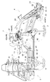
図1に、8条植え仕様に構成された施肥装置付き田植機の全体側面が、また、図2に、その全体平面がそれぞれ示されている。この施肥装置付き田植機は、操向可能な前輪1および操向不能な後輪2を備えて4輪駆動で走行する走行機体3の後部に、8条植え仕様の苗植付け装置4が、油圧シリンダ5によって駆動される平行四連リンク構造の昇降リンク機構6を介して昇降可能に連結されるとともに、機体後部に施肥装置7が備えられた基本構造を有している。
Hereinafter, comparative examples for clarifying the present invention will be described with reference to FIGS. 1 to 19, and then embodiments of the present invention will be described.
[Comparative Example]
The whole side surface of the rice transplanter with a fertilizer applied to the 8-row planting specification is shown in FIG. 1, and the whole plane is shown in FIG. In this rice transplanter with a fertilizer application, a
前記走行機体3の前部にはエンジン8が搭載され、その出力が前後進の切り換えが可能な主変速装置である静油圧式無段変速装置(HST)9に伝達され、その変速出力がミッションケース10に入力されて更に副変速装置(図示せず)でギヤ変速された後、前輪1と後輪2に伝達されるようになっており、静油圧式無段変速装置9を操作する主変速レバー11が、搭乗運転部のステアリングハンドル12の左脇に前後揺動可能に配備されるとともに、ミッションケース10内の副変速装置を操作する副変速レバー13が、搭乗運転部の運転座席14の左脇に配備されている。なお、搭乗運転部の右前足元には、踏み込みによって主変速レバー11を中立に強制復帰させるとともに走行系に備えたブレーキを制動作動させて機体を停止させる停止用のペダル15が配備されている。
An
前記苗植付け装置4には、角筒状の植付けフレーム18、前記ミッションケース10から取り出された作業用動力を受けるフィードケ−ス19、マット状苗を載置して一定ストロークで往復横移動する苗のせ台20、苗のせ台20の下端から一株分づつ苗を切り出して植付ける8組の回転式の植付け機構21、圃場の植付け予定箇所を均平にする5個の整地フロート22、等が備えられており、前記植付け機構21は、前記植付けフレーム18に後向き片持ち状に並列連結された4個の植付けケース23の後部左右に2組づつ装着されている。
In the
また、畦際近くにおいて全条(8条)より少ない条数での植付けを行うために、各植付けケース23の後部には、左右に装着された2条分の植付け機構21への動力伝達を断続する畦際クラッチ24がクラッチ入り付勢状態で備えられるとともに、苗のせ台20の各条ごとに備えられた苗送りベルト25の苗送り作動を植付け休止条に合わせて2条単位で停止する苗送りクラッチ26がクラッチ入り付勢状態で装備されている。
In addition, in order to perform planting with fewer than all the strips (8 strips) near the edge, power is transmitted to the
これら畦際クラッチ24および苗送りクラッチ26は苗のせ台20の背部に設けられた減速機付きの電動モータ27によって入り切り操作されるようになっている。つまり、図6の連係図に示すように、苗のせ台20の背部には前記電動モータ27によって一体に正逆回転される4個の回転カム28と各回転カム28によって操作される4個の操作レバー29が配備されるとともに、各操作レバー29で操作される4本の操作ワイヤ30が延出されている。各操作ワイヤ30はそれぞれ2本に分岐されて、その分岐ワイヤ30a,30bが2条単位で畦際クラッチ24と苗送りクラッチ26に連動連結されている。そして、回転カム28が中立位相にある時には全部の操作ワイヤ30が緩められて全部の畦際クラッチ24と苗送りクラッチ26がクラッチ「入」となって全条植え状態がもたらされ、回転カム28が中立位相から正方向に所定角度づつピッチ回動されることで、畦際クラッチ24と苗送りクラッチ26が左端のものから順に切り操作されて右側6条植え状態、右側4条植え状態、あるいは、右端2条植え状態がもたらされ、また、回転カム28が中立位相から逆方向に所定角度づつピッチ回動されることで、畦際クラッチ24と苗送りクラッチ26が右端のものから順に切り操作されて左側6条植え状態、左側4条植え状態、あるいは、左端2条植え状態がもたらされ、さらに、回転カム28が逆方向に大きく回動されることで全部の畦際クラッチ24と苗送りクラッチ26が切り操作されるようになっている。電動モータ27はステアリングハンドル12の右横に配備されたクラッチ選択操作部Aのスイッチ操作に基づいて後述のように作動制御されるようになっている。
The
前記苗植付け装置4は、人為的に昇降できる他に自動的に昇降制御可能となっている。つまり、図7のブロック図に示すように、運転座席14の右脇には植付けレバー31が配備されてポテンショメータ32でその操作位置が検出されるとともに、左右中央の整地フロート22を利用したセンサフロートSFの後部支点b周りの上下揺動変位がポテンショメータ33で検出され、これらポテンショメータ32,33と油圧シリンダ5の作動を司る電磁式の制御弁34が制御装置35に接続されている。
The
また、前記ミッションケース10内には苗植付け装置4への動力を断続する植付けクラッチ36が備えられるとともに、この植付けクラッチ36を入り切り操作する電動モータ37が前記制御装置35に接続されている。また、ステアリングハンドル12の右側には、中立復帰式の優先昇降用レバー38が上下揺動可能に装備されており、その上下操作を検出するスイッチ装置39が前記制御装置35に接続されている。更に、前記主変速レバー11の後進域への操作を検出する後進検出スイッチBSが前記制御装置35に接続されている。
The
前記植付けレバー31は「上昇」、「中立」、「下降」、「植付」、および、「自動」の各操作位置を選択可能であり、各操作位置で次のような作動が行われる。
The
「上昇」:制御弁34が上昇位置に切換えられ、油圧シリンダ5が短縮駆動されて、苗植付け装置4が上昇する。なお、苗植付け装置4が上限に到達したことが上限スイッチLSで検知されると制御弁34は自動的中立復帰されて上昇が停止される。
“Raising”: The
「中立」:制御弁34が中立位置に切換えられて、上昇作動あるいは下降作動が停止する。
“Neutral”: The
「下降」:苗植付け装置4がセンサフロートSFの上下変位に基づいて自動昇降される昇降制御モードであり、苗植付け装置4が圃場面より浮上している状態から「下降」位置に切り換えると、先ず、センサフロートSFのぶら下がりがポテンショメータ33で検知されて制御弁34が下降位置に切換えられ、苗植付け装置4が下降する。そして、苗植付け装置4が圃場面に到達してセンサフロートSFが所定の基準姿勢まで上方に揺動すると、制御弁34が中立位置に切換えられ下降が停止する。以後、センサフロートSFが接地圧の増大に基づいて基準姿勢から上方に変位すると上昇制御がなされるとともに、接地圧の減少に基づいて基準姿勢から下方に変位すると下降制御がなされ、センサフロートSFが所定の基準姿勢に維持されるように昇降制御が行われる。ただし、この「下降」位置では、植付けクラッチ36は切り状態に維持され、苗植付け装置4の自動昇降だけが行われる。
“Descent”: The raising / lowering control mode in which the
「植付」:上記「下降」位置と同様に苗植付け装置4の自動昇降が行われるとともに、電動モータ37を介しての植付けクラッチ36の入り操作が行われるものであり、植付け走行時に選択利用される。
“Planting”: The
「自動」:上記「植付」位置と同様のセンサフロートSFに基づく苗植付け装置4の自動昇降制御の機能をもたらすとともに、優先昇降レバー38による任意の昇降制御(優先昇降制御)と、主変速レバー11の後進位置への切り換えに基づく苗植付け装置4の自動上昇制御(バックアップ制御)とが以下のように実行される。
“Automatic”: The automatic raising / lowering control function of the
(優先昇降制御):苗植付け装置4が所定の基準姿勢を維持するよう昇降制御される状態で植付け走行を行って畦際に到達すると、優先昇降レバー38を上げ「U」位置にワンショット操作することで、苗植付け装置4は上限まで上昇制御されるとともに植付けクラッチ36が切り制御される。畦際での機体方向転換を終えると、優先昇降レバー38を下げ「D」位置に1回ワンショット操作することで元の自動昇降制御モードに復帰して、苗植付け装置4は接地するまで下降制御される。但し、この下降においては植付けクラッチ36は切り状態に維持される。方向転換および次行程に対する条合わせがすむと、タイミングを見はからって優先昇降レバー38を再び下げ「D」位置にワンショット操作することで、植付けクラッチ36が入り制御されて植付けを再開することができる。
(Priority raising / lowering control): When planting traveling is performed in a state where the
(バックアップ制御):畦際などで苗植付け装置4が下降している状態のまま、主変速レバー11を後進に切り換えると、これが後進検出スイッチBSで検出されて苗植付け装置4は上限まで自動的に上昇する。このとき、植付けクラッチ36が入っておれば上昇作動とともに切り制御され、後進によって苗植付け装置4の後部が畦などにぶつかることが未然に回避される。
(Backup control): When the main
前記施肥装置7は、運転座席14と苗植付け装置4との間において自走機体3上に搭載されており、粉粒状の肥料を貯留する肥料ホッパ41、この肥料ホッパ41内の肥料を繰り出す繰出し機構42、繰り出された肥料を供給ホース43を介して苗植付け装置4の各整地フロート24に備えた作溝器44に風力搬送するブロワ45、ブロワ駆動用の電動モータ46、搬送風分配用の送風管47、などを備えている。
The
各繰出し機構42は、肥料ホッパ41の下端に連結される繰出しケース48に2条分の繰出しロール49を並列装備して構成されており、4組の繰出し機構42が左右に並列配備されるとともに、各繰出し機構42に2本づつ前記供給ホース43が接続され、もって、8条分の肥料繰り出し供給が可能となっている。
Each
図8,9,10に示すように、前記繰出しケース48は、ロール軸心を通る分割面において上下に分割されており、上部ケース48aが肥料ホッパ41の下端に連結されるとともに、下部ケース48bが機体側に固定されている。そして、上部ケース48aに連結した支持ブラケット50が走行機体3から立設した後部施肥フレーム51に支点cを中心に前後に回動可能に構成されており、肥料ホッパ41および上部ケース48aを支点c周りに後方に回倒することで、繰出しケース48を開放してケース内の清掃や繰出しロール49の取り外し清掃などのメンテナンスを行うことが可能となっている。そして、前記支持ブラケット50に連結されたホッパ支持フレーム52と走行機体3から立設した前部施肥フレーム53とをバックル型の止め金具54で連結することで、上部ケース48aが下部ケース48bに接続された所定の作用位置に固定されるようになっている。また、ホッパ支持フレーム52と前部施肥フレーム53とに亘ってガススプリング55が架設されており、止め金具54を外して肥料ホッパ41および上部ケース48aを持上げ回動すると、図9に示すように、ガススプリング55の伸長付勢力によって肥料ホッパ41および上部ケース48aがメンテナンス可能な開放位置に保持されるようになっている。
As shown in FIGS. 8, 9, and 10, the feeding
図11に示すように、前記送風管47に搬送風を供給するブロア45には吸気用ダクト56が接続されてエンジン8の近傍にまで延出され、エンジン廃熱で暖められて乾燥した外気を吸入することで、搬送される肥料が吸湿して繰出し機構42や供給ホース43で固まることが防止されるようになっている。また、吸気用ダクト56の途中にはシャッタ57によって開閉される補助吸気口58が備えられており、このシャッタ57が以下のように前記主変速レバー11の変速操作によって開閉操作されて、補助吸気口58の開度が自動的に調整されるようになっている。
As shown in FIG. 11, an
主変速レバー11はエンジン8の調速機構59にワイヤ連係されており、主変速レバー11が中立位置にある時には調速機構59が所定のアイドリング状態となり、主変速レバー11が中立位置から前進域Fあるいは後進域Rの高速側に操作されるに連れて調速機構59が高速側にアクセルアップ操作されるようになっており、走行停止時には自動的にアクセルダウンされて燃費の向上および騒音低減が図られるとともに、高速走行になるほどエンジン出力が自動的に高められるようになっている。そして、主変速レバー11が高速側に操作されるに連れて前記シャッタ57が開放方向に操作されて補助吸気口58の開度が大きくなり、エンジン8がアクセルアップされてエンジン廃熱が多くなるに連れて補助吸気口58からの冷外気の吸入量を多くして、ブロワ45に吸引される外気温度の安定化が図られている。
The main
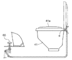
また、前記肥料ホッパ41の上端には後部の支点d周りに開閉揺動可能に上蓋41aが装備されている。図12に示すように、前記上蓋41aは支点dに備えたねじりバネ(図示せず)で閉じ付勢されるとともに、搭乗運転部における足元に配備されたペダル60にワイヤ連係されており、肥料の補給時に肥料袋を両手で持った状態でも前記ペダル60を踏み込むことで上蓋41aを開放操作することができ、踏み込みを解除することで上蓋41aを閉じることができるようになっている。
In addition, an
また、図14に示すように、前記肥料ホッパ41の内部の適所には肥料袋開封機構61が装備されている。この肥料袋開封機構61には、横断形状がC形に形成された筒状のカッタ62と、このカッタ62を外囲する筒状のスライドカバー63とが備えられており、スライドカバー63はバネ64で上向きに付勢されて常時はカッタ62を隠している。肥料の補給時には、肥料袋100を肥料袋開封機構61の上に押付けることで筒状カバー63が押し下げられて肥料袋100がカッタ62の上端刃先でC形に切断され、その後、肥料袋100を引き上げてホッパ内で振り動かすことで肥料を補給することができる。
Further, as shown in FIG. 14, a fertilizer
前記整地フロート22に備えられた作溝器44の内部には、一対の電極間の通電抵抗から肥料の付着堆積を検知する詰まり検出センサ65が装備されており、両電極に亘って付着する肥料の量が大きくなるにつれて電極間の通電抵抗値が低下し、これが予め設定された基準値を越えると運転部に配備された警報ランプ(報知手段)66が点滅作動して肥料詰まりが発生したことが運転作業者に知らせるようになっている。なお、警報ランプ66は苗補給を促す報知手段にも利用されており、苗のせ台20の各条ごとに装備した苗残量センサ69のいずれかが検知作動することによっても警報ランプ66が点滅作動するようになっている。
A clogging
図4に示すように、肥料詰まりを判断する前記基準値は、運転座席14の後方に配備された検知ユニット67の可変抵抗器68をダイヤル操作することで任意に変更調節可能となっており、これによって肥料詰まりの検出感度を調節することができるようになっている。つまり、基準値を大きく設定すると少しの肥料付着によって通電抵抗値が少し下がるだけで報知作動し、また、基準値を小さく設定すると肥料付着が進んで通電抵抗値が大きく低下してはじめて報知作動するものとなり、肥料の種類や圃場の状況、等に応じて検出感度の調整を行う。
As shown in FIG. 4, the reference value for determining fertilizer clogging can be arbitrarily changed and adjusted by dialing the
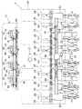
次に、繰出し機構42の駆動構造について説明する。図3,4,15に示すように、並列配備された4つの繰出し機構42に亘って全条共通の繰出し駆動軸71が横架され、この繰出し駆動軸71に備えた駆動ギヤ72と繰出しロール軸73に備えた従動ギヤ74とが咬合連動されるとともに、繰出し駆動軸71自体は、ミッションケース10から後輪2を軸支した後部伝動ケース16へ動力伝達を行う走行系伝動軸17に連動連結され、走行速度と同調した速度で繰出し機構42が繰り出し駆動されるようになっている。
Next, the drive structure of the
つまり、図3に示すように、前記走行系伝動軸17の後部に動力取出しケース75が装備され、走行系伝動軸17にベベルギヤ連動された出力軸76が動力取出しケース75の横側面から突設されている。そして、この出力軸76の端部に備えたクランクアーム77と前記繰出し機構42に備えた受動アーム78とが押し引きロッド79を介して連動連結され、クランクアーム77の一定方向回転に伴って受動アーム78が往復揺動し、その往復揺動が相反する駆動方向特性の2組の一方向クラッチ(図示せず)を介して繰出し駆動軸71に伝達され、繰出し駆動軸71が脈動的に一定方向に回転駆動されるようになっている。
That is, as shown in FIG. 3, a power take-out
また、動力取出しケース75は、出力軸76からの動力の取り出しを断続する施肥クラッチ80が備えられるとともに、この施肥クラッチ80は前記植付けクラッチ36を入り切り制御する電動モータ37に機械的に連動連結され、植付けクラッチ36の入り切りと施肥クラッチ80の入り切りが同調するようになっている。
Further, the power take-out
また、繰出し駆動軸71には各繰出し機構42への動力伝達を断続する繰出しクラッチ81が装備され、苗植付け装置4の畦際クラッチ24および苗送りクラッチ26を切って少数条の植付けを行う際に、植付け休止条に対応する施肥を休止することができるよう構成されている。
Further, the feeding
前記繰出しクラッチ81は、繰出し駆動軸71にシフト可能に装着したクラッチ片82を、駆動ギヤ74に軸心方向から咬合させる爪クラッチに構成されており、クラッチ片82はクラッチ入り方向にバネ83でスライド付勢されている。そして、クラッチ片82をシフト操作するクラッチアーム84が支点e周りに揺動可能に配備されている。
The
以下に、並列配備された4つの繰出しクラッチ81の操作構造について説明する。
Hereinafter, an operation structure of the four
図15に示すように、繰出し機構42の背部に沿って横長の支持フレーム85が固定配備され、この支持フレーム85に4個の前記クラッチアーム84が支点e周りに揺動可能に枢支連結されるとともに、右側の3個のクラッチアーム84と、支持フレーム85に支点f周りに揺動可能に枢支された中継操作レバー86とがロッド87を介して連動連結され、更に支持フレーム85に沿って横長のクラッチ操作部材88が長孔89とピン90を利用した左右一対のガイド手段Gを介して左右に直線移動可能に支持されている。
As shown in FIG. 15, a horizontally
クラッチ操作部材88には前記クラッチアーム84に左方向から接当作用する操作片88a、および、中継操作レバー86に右方向から接当作用する操作片88bが折り出し形成されており、クラッチ操作部材88が左右に移動することで繰出しクラッチ81を以下のように入り切り操作することが可能となっている。
The
〔全条施肥〕
図16(イ)に示すように、クラッチ操作部材88が左右移動方向における中立位置にあると、操作片88a,88bがクラッチアーム84および中継操作レバー86から離れた状態にあり、全部のクラッチアーム84がクラッチ「入」位置にある。
[All-row fertilization]
As shown in FIG. 16 (a), when the
〔右6条の施肥〕
図16(ロ)に示すように、クラッチ操作部材88が中立位置から1ピッチだけ右方向に移動されると、左端のクラッチアーム84が操作片88aによってクラッチ「切」位置に接当操作され、左端の繰出しクラッチ81だけが切り操作される。これによって左端2条の施肥を休止した右側6条の施肥が行われる。
[Right 6 fertilization]
As shown in FIG. 16 (b), when the
〔右4条の施肥〕
図16(ハ)に示すように、クラッチ操作部材88が更に1ピッチ右方向に移動すると、左側2つのクラッチアーム84が操作片88aによってクラッチ「切」位置に接当操作され、左側の2つの繰出しクラッチ81だけが切り操作される。これによって左側4条の施肥を休止した右側4条の施肥が行われる。
[Four fertilization on the right]
As shown in FIG. 16C, when the
〔右端2条の施肥〕
図16(ニ)に示すように、クラッチ操作部材88が更に1ピッチ右方向に移動すると、左側3つのクラッチアーム84が操作片88aによってクラッチ「切」位置に接当操作され、左側の3つの繰出しクラッチ81が切り操作される。これによって左側6条の施肥を休止した右端2条の施肥が行われる。
[
As shown in FIG. 16 (d), when the
〔全条休止〕
図16(ホ)に示すように、上記した〔右端2条の施肥〕状態から上記クラッチ操作部材88が更に右方向に移動されて右ストロークエンドまで移動されると、全部のクラッチアーム84がそれぞれ操作片88aによって接当されてクラッチ「切」位置に操作され、全条の施肥が休止される。
[All Articles Suspended]
As shown in FIG. 16 (e), when the
〔左6条の施肥〕
図17(イ)に示すように、クラッチ操作部材88が中立位置から1ピッチだけ左方向に移動すると、右端の中継操作レバー86が操作片88bによって接当操作されて右端のクラッチアーム84だけがクラッチ「切」位置に操作され、右端の繰出しクラッチ81だけが切り操作される。これによって右端2条の施肥を休止した左側6条の施肥が行われる。
[Left 6 fertilization]
As shown in FIG. 17 (a), when the
〔左4条の施肥〕
図17(ロ)に示すように、クラッチ操作部材88が更に1ピッチ左方向に移動すると、右側2つの中継操作レバー86が共に操作片88bによって接当操作されて右側2つのクラッチアーム84がクラッチ「切」位置に操作され、右側2つの繰出しクラッチ81だけが切り操作される。これによって右側4条の施肥を休止した左側4条の施肥が行われる。
[Left 4 fertilization]
As shown in FIG. 17 (b), when the
〔左端2条の施肥〕
図17(ハ)に示すように、クラッチ操作部材88が更に1ピッチ左方向に移動すると、3つの中継操作レバー86が共に操作片88bによって接当操作されて右側3つのクラッチアーム84がクラッチ「切」位置に操作され、右側3つの繰出しクラッチ81が切り操作される。これによって右側6条の施肥を休止した左端2条の施肥が行われる。
[
As shown in FIG. 17 (c), when the
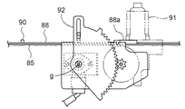
ここで、図18に示すように、前記クラッチ操作部材88は、減速機付きの電動モータ(アクチュエータの一例)91で支点g周りに左右に揺動される操作アーム92にピン係合されており、電動モータ91の正逆作動によってクラッチ操作部材88が左右に駆動移動されるようになっている。また、この電動モータ91はステアリングハンドル12の右横に配備された前記クラッチ選択操作部Aの操作に基づいて作動制御される。
Here, as shown in FIG. 18, the
図13に示すように、クラッチ選択操作部Aは、4個のランプ内臓型の押しボタンスイッチ95を縦方向に並列配備して構成されており、その選択操作によって以下のようにクラッチ制御が行われて種々の植付けパターンを現出することができる。 As shown in FIG. 13, the clutch selection operation unit A is configured by arranging four lamp built-in type push button switches 95 in parallel in the vertical direction, and clutch control is performed as follows by the selection operation. Various planting patterns can be revealed.
(1)〔全条植付け施肥〕
全部の押しボタンスイッチ95が消灯作動している状態では、全部の畦際クラッチ24と苗送りクラッチ26がクラッチ「入」状態になるとともに上記〔全条施肥〕状態がもたらされる。
(1) [All-row planting fertilization]
In a state where all the push button switches 95 are turned off, all the
(2)〔右6条の植付け施肥〕
最下方の押しボタンスイッチ95だけを押し操作してその内臓ランプ96を点灯作動させると、左端2条の畦際クラッチ24と苗送りクラッチ26だけがクラッチ「切」状態に操作されて、右6条の植付けが行われるとともに上記〔右6条の施肥〕状態がもたらされる。
(2) [6 planting fertilizers on the right]
When only the lowermost
(3)〔右4条の植付け施肥〕
下方2個の押しボタンスイッチ95を押し操作してそれぞれの内臓ランプ96を点灯作動させると、左側4条の畦際クラッチ24と苗送りクラッチ26がクラッチ「切」状態に操作されて、右4条の植付けが行われるとともに上記〔右4条の施肥〕状態がもたらされる。
(3) [4 planting fertilizers on the right]
When the two lower push button switches 95 are pressed to turn on the respective built-in
(4)〔右端2条の植付け施肥〕
下方3個の押しボタンスイッチ95を押し操作してそれぞれの内臓ランプ96を点灯作動させると、左側6条の畦際クラッチ24と苗送りクラッチ26がクラッチ「切」状態に操作されて、右端2条の植付けが行われるとともに上記〔右端2条の施肥〕状態がもたらされる。
(4) [Two right end planting fertilization]
When the lower three push button switches 95 are pressed and operated to turn on the built-in
(5)〔左6条の植付け施肥〕
最上方の押しボタンスイッチ95だけを押し操作してその内臓ランプ96を点灯作動させると、右端2条の畦際クラッチ24と苗送りクラッチ26だけがクラッチ「切」状態に操作され、左6条の植付けが行われるとともに上記〔左6条の施肥〕状態がもたらされる。
(5) [Left 6 planting fertilization]
When only the uppermost
(6)〔左4条の植付け施肥〕
上方2個の押しボタンスイッチ95を押し操作してそれぞれの内臓ランプ96を点灯作動させると、右側4条の畦際クラッチ24と苗送りクラッチ26がクラッチ「切」状態に操作され、左4条の植付けが行われるとともに上記〔左4条の施肥〕状態がもたらされる。
(6) [Left 4 planting fertilizer]
When the upper two push button switches 95 are pushed and operated to turn on the respective built-in
(7)〔左端2条の植付け施肥〕
上方3個の押しボタンスイッチ95を押し操作しそれぞれの内臓ランプ96を点灯作動させると、右側6条の畦際クラッチ24と苗送りクラッチ26がクラッチ「切」状態に操作されて、左端2条の植付けが行われるとともに上記〔左端2条の施肥〕状態がもたらされる。
(7) [Plant fertilization on the
When the upper three push button switches 95 are operated to turn on the built-in
(8)〔全条休止〕
全部の押しボタンスイッチ95を押し操作して内臓ランプ96を全て点灯作動させると、全部の畦際クラッチ24と苗送りクラッチ26がクラッチ「切」状態になり、全条の植付けが休止されるとともに上記〔全条施肥休止〕状態がもたらされる。
(8) [All Articles Suspended]
When all the push button switches 95 are pressed and all the built-in
なお、点灯作動している押しボタンスイッチ95を再度押し操作すると消灯作動して対応するクラッチ類は入り作動する。また、全部の押しボタンスイッチ95を押し操作して内臓ランプ96を全て点灯作動させて〔全条施肥休止〕状態をもたらした上で、別のスイッチ操作を行って電動モータ27だけを作動させて全部の畦際クラッチ24と苗送りクラッチ26をクラッチ「入」状態に復帰させ、施肥を行うことなく全条での植付けを行うことも可能である。
When the
クラッチ選択操作部Aを構成する4個の押しボタンスイッチ95は、下方ほど左側に偏るように斜めに隊列されており、植付けおよび施肥が休止される条の左右方向配置が押しボタンスイッチ95の左右方向への偏在位置から認識しやすいようになっている。なお、少数条植え作業は左端または右端の条からから順に休止するものであって、中間の条だけの植付けおよび施肥が休止されることはないので、押しボタンスイッチ95が上端または下端から順に押し操作されていない状態は操作間違いと判断して電動モータ27,91の作動が牽制阻止されるようになっている。
The four push button switches 95 constituting the clutch selection operation unit A are arranged obliquely so as to be biased to the left as it goes downward, and the horizontal arrangement of the strips where planting and fertilization are suspended is the left and right of the
また、少数条での植付け行程の次の植付け行程は全条で行われるので、少数条植付け行程を終えて畦際で機体の方向転換を行う際に、クラッチ選択操作部Aを〔全条植付け施肥〕状態に戻しておくことになるが、この戻し操作を忘れても自動的に〔全条植付け施肥〕状態に復帰させる手段が備えられている。つまり、前記植付けレバー31を「自動」位置に操作しておくと、少数条植付け行程を終えて畦際で機体の方向転換を行う際に、優先昇降レバー38を操作して苗植付け装置4を上昇させると、上限スイッチLSの検知に基づいて〔全条植付け施肥〕状態に復帰移動させるように電動モータ27,91が自動的に制御されるとともに、押しボタンスイッチ95の内臓ランプ96が消灯されるのである。なお、植付けレバー31を「自動」位置に操作しないで苗植付け装置4を昇降させる場合には、上記全条植付け施肥復帰作動は実行されることはなく、クラッチ選択操作部Aの選択操作のみによってクラッチ入り切り操作が行われる。
In addition, since the planting process following the planting process with a small number of strips is performed with all the strips, the clutch selection operation section A is set to [ Although it will return to the [fertilization] state, even if this return operation is forgotten, means for automatically returning to the [all-planting fertilization] state is provided. In other words, if the
〔実施形態〕Embodiment
以下、本発明の実施形態について説明する。Hereinafter, embodiments of the present invention will be described.
なお、実施形態における施肥装置付き田植機は、比較例で説明した施肥装置付き田植機とは繰出しクラッチ81の操作構造が異なるだけで、その他の構造は同じであるから、その異なる繰出しクラッチ81の操作構造についてのみ説明し、他の構造については説明を省略する。In addition, since the rice transplanter with a fertilizer applying apparatus in embodiment differs from the rice transplanter with a fertilizer applying apparatus demonstrated in the comparative example only in the operation structure of the
上記比較例では、繰出しクラッチ81の操作構造を、並列配備された繰出しクラッチ81群に沿って左右に長いクラッチ操作部材88を左右に直線移動させる形態としているが、本実施形態では、図20に示すように、クラッチ操作部材88を、繰出しクラッチ81群に沿って横架した操作軸88cに回転位相を異ならせた複数のカム板88dを連結した構造のものとし、前記操作軸88cを電動モータ(アクチュエータ)91で正逆に所定角度ずつ回転させることで、各カム板88dで各繰出しクラッチ81のクラッチ片82を直接にシフト操作して、一部の条、あるいは、全条の繰出し休止を行うように繰出しクラッチ81の操作構造を構成してある。
In the comparative example , the operation structure of the
以下、本発明の別実施形態について説明する。
(1)肥料ホッパ41および繰出しケース48の上部ケース48aを支点c周りに後方へ回倒して繰出しケース48を開放する構造において、前記ガススプリング55に代えて、前方への復帰回動を阻止する突っ張りロッド(図示せず)を装備し、肥料ホッパ41および上部ケース48aをメンテナンス位置まで回倒すると突っ張りロッドが自動的に係止作動して開放姿勢を保持するように構成することもできる。
Hereinafter, another embodiment of the present invention will be described.
(1) In the structure in which the
(2)図21に示すように、前記肥料ホッパ41の上蓋41aをバネ97で開放付勢するとともに、上蓋41aを係止金具98で閉じ位置に係止固定可能に構成し、かつ、係止金具98をペダル60の踏み込みによって係止解除操作可能に構成することで、手を使わずに上蓋41aを開放することも可能である。なお、この場合、肥料補給がすむと、上蓋41aを手で閉じて係止金具98で係止固定することになる。
(2) As shown in FIG. 21, the
(3)機体の方向転換に基づいて全条植付け施肥状態に自動復帰させるクラッチ自動復帰制御手段の機能を専用のスイッチ(図示せず)でオン・オフするように構成することもできる。 (3) The function of the clutch automatic return control means for automatically returning to the full-row planting fertilized state based on the direction change of the airframe can be configured to be turned on / off by a dedicated switch (not shown).
3 走行機体
4 苗植付け装置
7 施肥装置
42 繰出し機構
66 報知手段
81 繰出しクラッチ
82 クラッチ片
88 クラッチ操作部材
88c 操作軸
88d カム板
91 アクチュエータ(電動モータ)
A クラッチ選択操作部
3 traveling
66 Notification means 81 Feeding clutch
82
88c operation axis
A Clutch selection operation section
Claims (5)
左右に並列配備された複数の前記繰出しクラッチの近傍に、各繰出しクラッチに機械連係された横長のクラッチ操作部材をアクチュエータで左右向きの軸心周りに正逆に回転駆動可能に配備するとともに、前記クラッチ操作部材を、複数の前記繰出しクラッチに沿って横架した操作軸と、この操作軸に回転位相を異ならせて連結した複数のカム板とにより構成し、かつ、前記アクチュエータを作動させるクラッチ選択操作部を備え、このクラッチ選択操作部の操作によって前記アクチュエータを所定量作動させて前記クラッチ操作部材を左右向きの軸心周りに正逆に所定角度ずつ回転させることにより、それぞれの前記カム板で対応する前記繰出しクラッチのクラッチ片を直接にシフト操作して、選択した一部の前記繰出しクラッチあるいは全部の前記繰出しクラッチを切り操作可能に構成してあることを特徴とする施肥装置付き田植機。 In the rice transplanter with a fertilizer applicator equipped with a plurality of pay-out clutches for stopping a part of the full-length feed mechanism in the fertilizer applicator,
In the vicinity of a plurality of the feeding clutch in parallel deployed to the left and right, as well as rotatably driven deployed in forward and reverse about the axis of the laterally extending clutch operating member horizontally long that is mechanically linked to the feeding clutch actuator, said Clutch selection in which the clutch operating member is composed of an operating shaft horizontally mounted along the plurality of feeding clutches, and a plurality of cam plates connected to the operating shaft with different rotational phases, and the actuator is operated. Each of the cam plates is provided with an operation portion, and by operating the clutch selection operation portion by a predetermined amount to rotate the clutch operation member around the axial center in the right and left direction by a predetermined angle. directly to the shifting clutch piece of the corresponding feeding clutch, a part selected the feed clutch or Fertilizing device with rice transplanter, characterized in that said are operably configured off feeding clutch parts.
Priority Applications (1)
| Application Number | Priority Date | Filing Date | Title |
|---|---|---|---|
| JP2005129547A JP4533229B2 (en) | 2005-04-27 | 2005-04-27 | Rice transplanter with fertilizer application |
Applications Claiming Priority (1)
| Application Number | Priority Date | Filing Date | Title |
|---|---|---|---|
| JP2005129547A JP4533229B2 (en) | 2005-04-27 | 2005-04-27 | Rice transplanter with fertilizer application |
Publications (3)
| Publication Number | Publication Date |
|---|---|
| JP2006304649A JP2006304649A (en) | 2006-11-09 |
| JP2006304649A5 JP2006304649A5 (en) | 2009-02-05 |
| JP4533229B2 true JP4533229B2 (en) | 2010-09-01 |
Family
ID=37472264
Family Applications (1)
| Application Number | Title | Priority Date | Filing Date |
|---|---|---|---|
| JP2005129547A Active JP4533229B2 (en) | 2005-04-27 | 2005-04-27 | Rice transplanter with fertilizer application |
Country Status (1)
| Country | Link |
|---|---|
| JP (1) | JP4533229B2 (en) |
Families Citing this family (3)
| Publication number | Priority date | Publication date | Assignee | Title |
|---|---|---|---|---|
| JP4996492B2 (en) * | 2008-01-30 | 2012-08-08 | 株式会社クボタ | Rice transplanter with fertilizer application |
| JP6653523B2 (en) * | 2015-02-10 | 2020-02-26 | 松山株式会社 | Farm work machine |
| CN107787620A (en) * | 2016-08-31 | 2018-03-13 | 金泰旭 | Accurate fertilizing rotary tillage seeding integrated machine automatic clutch transmission mechanism |
Citations (5)
| Publication number | Priority date | Publication date | Assignee | Title |
|---|---|---|---|---|
| JP2000139135A (en) * | 1998-11-04 | 2000-05-23 | Yanmar Agricult Equip Co Ltd | Clutch driver in rice transplanter |
| JP2002017115A (en) * | 2000-07-05 | 2002-01-22 | Yanmar Agricult Equip Co Ltd | Rice transplanter |
| JP2002112609A (en) * | 2000-10-04 | 2002-04-16 | Yanmar Agricult Equip Co Ltd | Planting unit mechanism for sulky rice transplanter |
| JP2002262624A (en) * | 2001-03-06 | 2002-09-17 | Kubota Corp | Sulky rice transplanter |
| JP2004298122A (en) * | 2003-03-31 | 2004-10-28 | Kubota Corp | Rice transplanter |
Family Cites Families (2)
| Publication number | Priority date | Publication date | Assignee | Title |
|---|---|---|---|---|
| JPH08103126A (en) * | 1994-10-07 | 1996-04-23 | Kubota Corp | Rice transplanter |
| JPH09294428A (en) * | 1996-04-30 | 1997-11-18 | Kubota Corp | Sulky working machine |
-
2005
- 2005-04-27 JP JP2005129547A patent/JP4533229B2/en active Active
Patent Citations (5)
| Publication number | Priority date | Publication date | Assignee | Title |
|---|---|---|---|---|
| JP2000139135A (en) * | 1998-11-04 | 2000-05-23 | Yanmar Agricult Equip Co Ltd | Clutch driver in rice transplanter |
| JP2002017115A (en) * | 2000-07-05 | 2002-01-22 | Yanmar Agricult Equip Co Ltd | Rice transplanter |
| JP2002112609A (en) * | 2000-10-04 | 2002-04-16 | Yanmar Agricult Equip Co Ltd | Planting unit mechanism for sulky rice transplanter |
| JP2002262624A (en) * | 2001-03-06 | 2002-09-17 | Kubota Corp | Sulky rice transplanter |
| JP2004298122A (en) * | 2003-03-31 | 2004-10-28 | Kubota Corp | Rice transplanter |
Also Published As
| Publication number | Publication date |
|---|---|
| JP2006304649A (en) | 2006-11-09 |
Similar Documents
| Publication | Publication Date | Title |
|---|---|---|
| JP5054575B2 (en) | Rice transplanter | |
| JP2006094753A (en) | Engine controlling structure of riding type rice transplanter | |
| JP2010207104A (en) | Rice transplanter | |
| JP6830425B2 (en) | Passenger rice transplanter | |
| JP4533229B2 (en) | Rice transplanter with fertilizer application | |
| CN108337946A (en) | Agriculture working | |
| JP2010035422A5 (en) | ||
| JP2007236249A (en) | Operational structure of implement | |
| JP2006304649A5 (en) | ||
| KR101859776B1 (en) | Notification control structure for field feeding work vehicle | |
| JP4532763B2 (en) | Passenger rice transplanter | |
| JP5505023B2 (en) | Seedling transplanter | |
| JP2011030439A (en) | Riding-type direct sowing machine | |
| JP2010094134A (en) | Engine control structure of riding type rice transplanter | |
| JP5678851B2 (en) | Seedling transplanter | |
| JP2012157288A (en) | Seedling transplanter | |
| JP2013053605A (en) | Engine stop operation structure of working vehicle | |
| JP2006094743A (en) | Rice plant transplanter | |
| JP2016140293A (en) | Seedling transplanter | |
| JP3632378B2 (en) | Ride type seedling planting machine | |
| JP2013066391A5 (en) | ||
| JP2009100714A (en) | Seedling-planting apparatus | |
| JP6171845B2 (en) | Seedling transplanter | |
| JP2005160405A (en) | Riding type implement with fertilizing device | |
| JP2001061309A (en) | Rice planting machine |
Legal Events
| Date | Code | Title | Description |
|---|---|---|---|
| A621 | Written request for application examination |
Free format text: JAPANESE INTERMEDIATE CODE: A621 Effective date: 20070919 |
|
| A521 | Written amendment |
Free format text: JAPANESE INTERMEDIATE CODE: A523 Effective date: 20081211 |
|
| A977 | Report on retrieval |
Free format text: JAPANESE INTERMEDIATE CODE: A971007 Effective date: 20090723 |
|
| A131 | Notification of reasons for refusal |
Free format text: JAPANESE INTERMEDIATE CODE: A131 Effective date: 20090730 |
|
| A521 | Written amendment |
Free format text: JAPANESE INTERMEDIATE CODE: A523 Effective date: 20090925 |
|
| TRDD | Decision of grant or rejection written | ||
| A01 | Written decision to grant a patent or to grant a registration (utility model) |
Free format text: JAPANESE INTERMEDIATE CODE: A01 Effective date: 20100513 |
|
| A01 | Written decision to grant a patent or to grant a registration (utility model) |
Free format text: JAPANESE INTERMEDIATE CODE: A01 |
|
| A61 | First payment of annual fees (during grant procedure) |
Free format text: JAPANESE INTERMEDIATE CODE: A61 Effective date: 20100611 |
|
| R150 | Certificate of patent or registration of utility model |
Ref document number: 4533229 Country of ref document: JP Free format text: JAPANESE INTERMEDIATE CODE: R150 Free format text: JAPANESE INTERMEDIATE CODE: R150 |
|
| FPAY | Renewal fee payment (event date is renewal date of database) |
Free format text: PAYMENT UNTIL: 20130618 Year of fee payment: 3 |
|
| FPAY | Renewal fee payment (event date is renewal date of database) |
Free format text: PAYMENT UNTIL: 20130618 Year of fee payment: 3 |
|
| FPAY | Renewal fee payment (event date is renewal date of database) |
Free format text: PAYMENT UNTIL: 20140618 Year of fee payment: 4 |