JP4532455B2 - Immersion lithography apparatus and method - Google Patents
Immersion lithography apparatus and method Download PDFInfo
- Publication number
- JP4532455B2 JP4532455B2 JP2006287405A JP2006287405A JP4532455B2 JP 4532455 B2 JP4532455 B2 JP 4532455B2 JP 2006287405 A JP2006287405 A JP 2006287405A JP 2006287405 A JP2006287405 A JP 2006287405A JP 4532455 B2 JP4532455 B2 JP 4532455B2
- Authority
- JP
- Japan
- Prior art keywords
- cleaning
- plate
- voltage
- module
- cleaned
- Prior art date
- Legal status (The legal status is an assumption and is not a legal conclusion. Google has not performed a legal analysis and makes no representation as to the accuracy of the status listed.)
- Active
Links
Images


Classifications
-
- G—PHYSICS
- G03—PHOTOGRAPHY; CINEMATOGRAPHY; ANALOGOUS TECHNIQUES USING WAVES OTHER THAN OPTICAL WAVES; ELECTROGRAPHY; HOLOGRAPHY
- G03F—PHOTOMECHANICAL PRODUCTION OF TEXTURED OR PATTERNED SURFACES, e.g. FOR PRINTING, FOR PROCESSING OF SEMICONDUCTOR DEVICES; MATERIALS THEREFOR; ORIGINALS THEREFOR; APPARATUS SPECIALLY ADAPTED THEREFOR
- G03F7/00—Photomechanical, e.g. photolithographic, production of textured or patterned surfaces, e.g. printing surfaces; Materials therefor, e.g. comprising photoresists; Apparatus specially adapted therefor
- G03F7/70—Microphotolithographic exposure; Apparatus therefor
- G03F7/708—Construction of apparatus, e.g. environment aspects, hygiene aspects or materials
- G03F7/70908—Hygiene, e.g. preventing apparatus pollution, mitigating effect of pollution or removing pollutants from apparatus
- G03F7/70925—Cleaning, i.e. actively freeing apparatus from pollutants, e.g. using plasma cleaning
-
- B—PERFORMING OPERATIONS; TRANSPORTING
- B08—CLEANING
- B08B—CLEANING IN GENERAL; PREVENTION OF FOULING IN GENERAL
- B08B3/00—Cleaning by methods involving the use or presence of liquid or steam
- B08B3/04—Cleaning involving contact with liquid
- B08B3/10—Cleaning involving contact with liquid with additional treatment of the liquid or of the object being cleaned, e.g. by heat, by electricity or by vibration
- B08B3/12—Cleaning involving contact with liquid with additional treatment of the liquid or of the object being cleaned, e.g. by heat, by electricity or by vibration by sonic or ultrasonic vibrations
-
- G—PHYSICS
- G03—PHOTOGRAPHY; CINEMATOGRAPHY; ANALOGOUS TECHNIQUES USING WAVES OTHER THAN OPTICAL WAVES; ELECTROGRAPHY; HOLOGRAPHY
- G03F—PHOTOMECHANICAL PRODUCTION OF TEXTURED OR PATTERNED SURFACES, e.g. FOR PRINTING, FOR PROCESSING OF SEMICONDUCTOR DEVICES; MATERIALS THEREFOR; ORIGINALS THEREFOR; APPARATUS SPECIALLY ADAPTED THEREFOR
- G03F7/00—Photomechanical, e.g. photolithographic, production of textured or patterned surfaces, e.g. printing surfaces; Materials therefor, e.g. comprising photoresists; Apparatus specially adapted therefor
- G03F7/70—Microphotolithographic exposure; Apparatus therefor
- G03F7/70216—Mask projection systems
- G03F7/70341—Details of immersion lithography aspects, e.g. exposure media or control of immersion liquid supply
-
- H—ELECTRICITY
- H01—ELECTRIC ELEMENTS
- H01L—SEMICONDUCTOR DEVICES NOT COVERED BY CLASS H10
- H01L21/00—Processes or apparatus adapted for the manufacture or treatment of semiconductor or solid state devices or of parts thereof
- H01L21/67—Apparatus specially adapted for handling semiconductor or electric solid state devices during manufacture or treatment thereof; Apparatus specially adapted for handling wafers during manufacture or treatment of semiconductor or electric solid state devices or components ; Apparatus not specifically provided for elsewhere
- H01L21/67005—Apparatus not specifically provided for elsewhere
- H01L21/67011—Apparatus for manufacture or treatment
- H01L21/67017—Apparatus for fluid treatment
Description
本発明は、液浸リソグラフィ装置及び方法に関する。 The present invention relates to an immersion lithographic apparatus and method.
半導体製造技術が、例えば65ナノメートル,45ナノメートル,及びそれ以下などの微小形状について継続的に発展するにつれて、液浸リソグラフィ方法が採用されてきている。 Immersion lithography methods have been adopted as semiconductor manufacturing technology continues to evolve for micro features such as 65 nanometers, 45 nanometers and below.
なお、本発明は、2005年10月24日に出願された米国特許出願第60/729565号の利益を主張し、その内容は参考のためこの明細書に添付される。 The present invention claims the benefit of US Patent Application No. 60/729565 filed on Oct. 24, 2005, the contents of which are attached to this specification for reference.
本情報開示は、以下の同一出願人による米国特許出願に関し、全情報開示は参考のためこの明細書に添付される
(1)2004年8月4日に出願され、本発明と同一の発明者及び同一の譲受人である米国特許出願第(代理人整理番号TSMC2003−1545)号「高周波超音波液浸リソグラフィ露光装置及び方法」
(2)2005年10月15日に出願され、本発明と同一の発明者及び同一の譲受人である米国特許出願第(代理人整理番号TSMC2004−0553)号「液浸リソグラフィに適した露光方法及び装置」
(3)出願され(日時不明)、本発明と同一の発明者及び同一の譲受人である米国特許出願第(代理人整理番号TSMC2005−0022)号「液浸リソグラフィに適した装置及び方法」
The present disclosure relates to the following US patent applications filed by the same applicant, the entire disclosure of which is attached to this specification for reference: (1) filed on August 4, 2004, the same inventor as the present invention; And US Patent Application No. (Attorney Docket No. TSMC2003-1545), the same assignee, "High-frequency ultrasonic immersion lithography exposure apparatus and method"
(2) U.S. Patent Application No. (Attorney Docket No. TSMC2004-0553) filed on October 15, 2005 and having the same inventor and assignee as the present invention, “Exposure Method Suitable for Immersion Lithography” And equipment "
(3) U.S. Patent Application No. (Attorney Docket No. TSMC2005-0022) filed (date unknown) and the same inventor and assignee as the present invention "Apparatus and Method Suitable for Immersion Lithography"
しかしながら、液浸リソグラフィシステムを用いる露光工程の間は、例えば粒子や水残留物などの汚れが液浸リソグラフィシステム内に取り込まれ、その中で処理される半導体ウエハをさらに汚す虞がある。このような汚れは、不良や歩留まりの悪化を引き起こし得る。 However, during the exposure process using the immersion lithography system, for example, dirt such as particles and water residues may be incorporated into the immersion lithography system and further contaminate the semiconductor wafer being processed therein. Such contamination can cause defects and yield deterioration.
本リソグラフィ装置は、結像レンズモジュールと、前記結像レンズモジュールの下方に配置され基板を保持するよう構成された基板テーブルと、リソグラフィ装置の洗浄に適合された洗浄モジュールとを備え、前記洗浄モジュールは、第一の板体と、第一の導電性板体を備え、前記第一の板体から間隔をあけて配置された第二の板体と、第二の導電性板体を備え、前記第二の板体から間隔をあけて配置された第三の板体と、前記第一の板体と前記第二の板体との間の進入路と、前記第二の板体と前記第三の板体との間の進出路とを備え、前記第一の導電性板体と前記第二の導電性板体は、第一の電圧に接続するものである。 This lithographic apparatus includes an imaging lens module and a substrate table configured to hold a substrate disposed below the imaging lens module and a cleaning module adapted to clean the lithography apparatus, wherein the cleaning module Comprises a first plate, a first conductive plate, a second plate disposed at a distance from the first plate, and a second conductive plate, A third plate disposed at a distance from the second plate, an approach path between the first plate and the second plate, the second plate and the An advancing path between the third plate body and the first conductive plate body and the second conductive plate body are connected to the first voltage.
本装置は、前記結像レンズモジュールと前記基板テーブル上の基板との間の空間へ液浸流体を供給するよう構成された液浸流体保持モジュールをさらに備える。 The apparatus further comprises an immersion fluid holding module configured to supply immersion fluid to a space between the imaging lens module and the substrate on the substrate table.
本装置は、第二の電圧に接続した洗浄されるべき構成の前記洗浄モジュールが、前記結像レンズ,前記基板テーブル,及び前記液浸流体保持モジュールのうち少なくとも一つを洗浄するよう作動可能である。 The apparatus is operable such that the cleaning module configured to be cleaned connected to a second voltage cleans at least one of the imaging lens, the substrate table, and the immersion fluid holding module. is there.
本装置は、前記洗浄モジュールが、前記進入路を経て通過し、前記洗浄されるべき構成の表面を通り過ぎる帯電ガスを供給するために、帯電ガス入口を備える。 The apparatus includes a charged gas inlet for the cleaning module to supply charged gas that passes through the entry path and passes through the surface of the configuration to be cleaned .
本装置は、前記帯電ガスが、前記洗浄されるべき構成の表面から前記進出路に移動する。 In this apparatus, the charged gas moves from the surface of the structure to be cleaned to the advance path.
本装置は、前記帯電ガスが、帯電ガス噴出器、イオンシャワー、および前記第一の板体と前記第二の板体による発生、から成る群から選択されて供給されるものである。 In this apparatus, the charged gas is selected and supplied from the group consisting of a charged gas ejector, an ion shower, and generation by the first plate and the second plate .
本装置は、前記第一の電圧は負の電圧であり、前記第二の電圧は正の電圧である。 In the apparatus, the first voltage is a negative voltage, and the second voltage is a positive voltage.
あるいは本装置は、前記第一の電圧は正の電圧であり、前記第二の電圧は負の電圧である。 Alternatively, in the apparatus, the first voltage is a positive voltage, and the second voltage is a negative voltage.
本方法は、第一の板体と、第一の導電性板体を備え、前記第一の板体から間隔をあけて配置された第二の板体と、第二の導電性板体を備え、前記第二の板体から間隔をあけて配置された第三の板体と、前記第一の板体と前記第二の板体との間の進入路と、前記第二の板体と前記第三の板体との間の進出路とを備えた洗浄モジュールとを具備するリソグラフィ装置の準備と、前記洗浄モジュールを利用することによる前記リソグラフィ装置に対する洗浄工程の実行と、結像層で表面を覆われた基板に対する露光工程の実行とから構成される。 The method includes a first plate body, a first conductive plate body, a second plate body spaced from the first plate body, and a second conductive plate body. A third plate disposed at a distance from the second plate, an approach path between the first plate and the second plate, and the second plate And a cleaning module having an advancing path between the third plate body , preparation of a lithographic apparatus, execution of a cleaning process on the lithographic apparatus using the cleaning module, and imaging layer And performing an exposure process on the substrate whose surface is covered with.
本方法は、前記洗浄工程の機能がさらに、前記第一の導電性板体と前記第二の導電性板体に第一の電圧を印加し、前記リソグラフィ装置の洗浄されるべき構成に第二の電圧を印加し、前記洗浄されるべき構成の表面に、前記進入路を経て通過する帯電ガスを導入し、前記帯電ガスを利用して、前記洗浄されるべき構成から前記進出路へ、前記洗浄されるべき構成に付着する粒子を追い出すことより構成される。In this method, the function of the cleaning step is further applied to a configuration in which the first voltage is applied to the first conductive plate and the second conductive plate, and the lithographic apparatus is to be cleaned. Is applied to the surface of the structure to be cleaned, the charged gas passing through the approach path, and the charged gas is used to move the structure to be cleaned from the structure to be advanced to the advance path. Composed of expelling particles adhering to the composition to be cleaned.
あるいは本方法は、前記洗浄工程の機能がさらに、前記第一の導電性板体と前記第二の導電性板体に第一の電圧を印加し、前記リソグラフィ装置の洗浄されるべき構成に第二の電圧を印加し、前記洗浄されるべき構成の表面に、前記進入路を経て通過する帯電ガスを導入し、前記帯電ガスを利用して、前記洗浄されるべき構成から前記進出路へ、前記洗浄されるべき構成に付着する粒子を取り除くことより構成される。Alternatively, in the method, the function of the cleaning step is further applied to the configuration in which the first voltage is applied to the first conductive plate and the second conductive plate to be cleaned of the lithographic apparatus. Applying a second voltage, introducing a charged gas that passes through the approach path to the surface of the structure to be cleaned, and using the charged gas, from the structure to be cleaned to the advance path, It consists of removing particles adhering to the structure to be cleaned.
本方法は、前記洗浄されるべき構成が、結像レンズ,基板テーブル,及び液浸流体保持モジュールのうち少なくとも一つである。In the method, the structure to be cleaned is at least one of an imaging lens, a substrate table, and an immersion fluid holding module.
本方法は、帯電ガス噴出器、イオンシャワー、および前記第一の板体と前記第二の板体による発生、から成る群から選択された前記帯電ガスを供給するために、帯電ガス入口を導入する。The method introduces a charged gas inlet to supply the charged gas selected from the group consisting of a charged gas ejector, an ion shower, and generation by the first plate and the second plate. To do.
本方法は、前記第一の電圧は負の電圧であり、前記第二の電圧は正の電圧である。In the method, the first voltage is a negative voltage and the second voltage is a positive voltage.
あるいは本方法は、前記第一の電圧は正の電圧であり、前記第二の電圧は負の電圧である。Alternatively, in the method, the first voltage is a positive voltage and the second voltage is a negative voltage.
本開示内容における外観は、添付図と共に読むときに以下の詳細な説明から最もよく理解される。標準的技法に従って、種々の特徴が縮尺で描かれないことに留意されたい。つまり、種々の特徴の寸法は、議論の明快化のために、適宜、増加又は減少され得る。 The appearance in this disclosure is best understood from the following detailed description when read in conjunction with the accompanying drawings. Note that, according to standard techniques, the various features are not drawn to scale. That is, the dimensions of the various features can be increased or decreased as appropriate for clarity of discussion.
以下の開示内容は、種々の実施形態の異なる特徴を有する多くの異なる実施例又は用例を提供することが理解される。処理及び構成要素の具体的な実施例は、本開示内容を簡略化するために、以下に説明される。もちろん、これらはただの例にすぎず、限定を意味するものではない。さらに、本開示内容は、種々の実施例中における参照番号及び/又は見出し文字を繰り返す場合がある。この繰り返しは、簡略化及び明瞭化の目的であり、議論された種々の実施例及び/又は構成間の関係をそれ自身決定づけるものではない。 It is understood that the following disclosure provides many different examples or examples with different features of various embodiments. Specific examples of processes and components are described below to simplify the present disclosure. Of course, these are only examples and are not meant to be limiting. Further, the present disclosure may repeat reference numbers and / or headings in various embodiments. This repetition is for the purpose of simplification and clarity and does not itself determine the relationship between the various embodiments and / or configurations discussed.
図1を参照すると、図示されたものは、液浸リソグラフィシステム100における実施例の概略図である。システム100は、パターン形成するためのシステム100によって処理される基板を保持するために、基板テーブル110を備える。基板テーブル110は、基板ステージでもよく、又はその一部として基板ステージを備えてもよい。基板テーブル110は、システム100に対して基板を固定しかつ移動させることが可能である。例えば、基板テーブル110は、基板配列,ステップ移動,及びスキャンのための並進及び/又は回転の移動ができるように設計されてもよい。基板テーブル110は、正確な移動を行うに適した種々の構成要素を備えてもよい。
With reference to FIG. 1, illustrated is a schematic diagram of an embodiment of an
基板テーブル110によって保持され、システム100によって処理される基板は、例えばシリコンウエハなどの半導体ウエハであり得る。また、前記半導体ウエハは、元素半導体,化合物半導体,半導体合金,又はそれらの組み合わせを含み得る。前記半導体ウエハは、例えば、パターン化されたポリシリコン,金属,及び/又は誘電体などの一乃至複数の材料層を含んでもよい。前記基板は、その上に形成された結像層をさらに含み得る。前記結像層は、パターン作成のための露光工程に対して反応の良いフォトレジスト層(レジスト層,感光層,パターニング層)であり得る。前記結像層は、ポジティブ又はネガティブ型レジスト材料であってもよく、多層構造を有していてもよい。ある典型的なレジスト材料は、化学増幅(CA)レジストである。
The substrate held by the substrate table 110 and processed by the
液浸リソグラフィシステム100は、一乃至複数の結像レンズシステム(“レンズシステム”と言う)120を備える。半導体ウエハは、レンズシステム120下方で基板テーブル110上に配置され得る。レンズシステム120は、単レンズ又は複合レンズ及び/又はその他のレンズ構成を具備し得る照明系(例えば集光装置)をさらに備え得る、又は一体であり得る。例えば、照明系は、マイクロレンズアレイ,シャドウマスク,及び/又は他の構造を備えてもよい。レンズシステム120は、単レンズ体又は複数のレンズ体を具備する対物レンズをさらに備えてもよい。各レンズ体は、透明基板を備えても良く、複数のコーティング層をさらに備えてもよい。透明基板は、従来型の対物レンズであってもよく、石英ガラス(SiO2),フッ化カルシウム(CaF2),フッ化リチウム(LiF),フッ化バリウム(BaF2),又は他の適した材料から成るものでもよい。各レンズ体に使用される材料は、吸収及び散乱を最小限にするためにリソグラフィ工程で使用される光波長に基づいて選択され得る。
The
システム100は、例えば液浸流体又は洗浄流体などの流体140を保持するための液浸流体保持モジュール130を備える。液浸流体保持モジュール130は、レンズシステム120の近く(例えば周囲)に配置されてもよく、液浸流体を保持することに加えて、他の機能のために設計されてもよい。液浸流体保持モジュール130とレンズシステム120は、液浸ヘッドを作り上げる(少なくとも一部)。液浸流体は、水(水溶液又は純水−DIW),高n流体(nは屈折率、193nm波長でn値は1.44より大きい),ガス,又は他の適した流体を含み得る。洗浄流体は、DIW,ガス,又は例えば周知のSC−1,SC−2,又はピランハ溶液など他の標準的な洗浄溶液を含み得る。種々の洗浄流体は、これらに限定されないが、イオン界面活性剤,非イオン界面活性剤,溶媒,NH4OH,H2O2,O3,PGME/PGMEA(プロピレングリコールモノメチルエーテル/プロピレングリコールモノメチルエーテルアセテート),シクロヘキサノール,イソプロピルアルコール(IPA),アセトン,アルコール,モノエタノールアミン(MEA)及びそれらの組み合わせを含み得る。ガスは、これらに限定されないが、O3,プラズマガス及びUV励起ガスを含み得る。選択されるプラズマ及びUV励起ガスは、限定されないが、O2,N2,Ar又は空気を含み得る。
The
液浸流体保持モジュール130は、露光工程用の液浸流体を供給する、洗浄用の洗浄流体を供給する、乾燥用のパージ空気を供給する、パージ(排除)される流体を除去する、及び/又は他の適当な機能を果たすための様々な装置(又はノズル)を備えてもよい。特に、モジュール130は、レンズシステム120と基板テーブル110上の基板との間の空間内に、液浸流体を供給及び移送するために、液浸流体入口としての開口部132aを備え得る。開口部132a及び/又は追加の開口部132bは、共同で、洗浄のための洗浄流体又は洗浄ガスを供給することができる。或いは、洗浄流体は、追加の洗浄流体開口部を通じて供給されてもよい。モジュール130は、液浸流体,洗浄流体又はパージされるべき他の流体を除去するために、出口としての開口部134を備え得る。モジュール130は、流体残留物をパージし、洗浄された表面を乾燥させるための乾燥ガスを供給するために、開口部136を備え得る。このような洗浄工程は、約0.1秒から30分までにわたる範囲の継続時間を有し得る。
The immersion
システム100は、基板テーブル110とレンズシステム120との間の空間に満たされた洗浄流体へ、超音波エネルギーを導入するよう作動可能な1つの超音波ユニット又は複数の超音波ユニット150を備える。超音波ユニット150は、液浸流体保持モジュール130及び/又は基板テーブル110に組み込まれるよう構成される。或いは、超音波ユニット150は、システム100の他の構成と一体化されてもよい。超音波ユニット150は、効果的な洗浄のための超音波エネルギーを供給するよう構成される。例えば、超音波ユニット150は、基板テーブル110及び/又は液浸流体保持モジュール130に内蔵されてもよく、超音波力が洗浄流体へ十分運ばれるように、洗浄流体で満たされた空間に近接又は隣接して配置されてもよい。超音波ユニット150は、周知の圧電素子を通じて電気エネルギーを超音波エネルギーに変換する超音波発生器を備えてもよい。超音波ユニット150は、例えば水晶振動子,バリウムチタネート,セラミック圧電材料,及び他の適した材料などの圧電材料を備えてもよい。超音波ユニット150は、およそ1kHzから1GHzまでにわたる範囲の周波数で超音波エネルギーを発生可能なように設計されてもよい。超音波ユニット150は、効果的な洗浄のための洗浄流体へ超音波力を伝達することができる。伝達された超音波力は、およそ1ミリワットから1キロワットまでにわたる範囲とすればよい。超音波力及び周波数は、所定の手法に従って調整され得る。各超音波ユニットは、様々な洗浄要求及び性能に応じて、個別に調整及び生成され得る。
The
また、システム100は、洗浄流体源から洗浄流体を供給するために、洗浄流体供給器160を備える。洗浄流体供給器160は、液浸流体保持モジュール130と一体化してもよい。また、システム100は、所定の手法に従う一層高い温度へ洗浄流体を加熱するよう設計及び構成されてもよく、洗浄流体供給器160の近傍に配置されたヒーター170を備え得る。例えば、洗浄流体は、およそ25℃から125℃までにわたる範囲の温度に加熱され得る。特定の例では、洗浄流体は、約40℃の温度に加熱され得る。ヒーター170には、例えば赤外線加熱,マイクロ波加熱,及び誘導性コイルなどの適した技術が利用され得る。或いは、洗浄流体は、システム100における洗浄流体源の外側で加熱された後、システム内に導入されてもよい。
The
液浸リソグラフィシステム100は、放射線源をさらに備えてもよい。放射線源は、紫外線(UV)又は極端UV(EUV)光源に適するものでもよい。例えば、放射線源は、436nm(G線)又は365nm(I線)の波長を有する水銀ランプ、248nm波長のフッ化クリプトン(KrF)エキシマレーザ、193nm波長のフッ化アルゴン(ArF)エキシマレーザ、157nm波長のフッ化物(F2)エキシマレーザ、又は所望の波長(すなわち、略100nm以下)を有する他の光源とすればよい。
The
フォトマスク(マスク又はレチクルとも言う)は、液浸リソグラフィ工程中にシステム100内へ導入され得る。マスクは、透明基板とパターン化された吸着層を備えてもよい。透明基板には、例えばホウケイ酸ガラスやソーダ石灰ガラスなどの比較的欠点が無い石英ガラス(SiO2)を使用すればよい。透明基板には、フッ化カルシウム及び/又は他の適した材料を使用してもよい。パターン化された吸着層は、複数の工程と、例えば、クロム(Cr)又は酸化鉄から成る金属膜を堆積する、又はMoSi,ZrSiO,SiN,及び/又はTiNから成る無機物膜などの複数の材料とを使用して形成され得る。
A photomask (also referred to as a mask or reticle) may be introduced into the
上述のシステム100は、露光工程に加えて、洗浄工程を実行するために利用できる。超音波ユニット150及び上述の洗浄機構と一体化された液浸リソグラフィシステム100は、基板テーブル110,レンズシステム120,及び液浸流体保持モジュール130を含むシステム100の様々な構成に対して、効果的な洗浄機能を提供できる。或いは、システム100はドライフォトリソグラフィパターニング工程にも利用でき、モジュール130は専用洗浄機能のためだけに異なって設計されてもよい。
The
図2は、液浸リソグラフィシステム200における別の実施例の概略図を示す。システム200は、洗浄流体供給器210及び洗浄流体排液器220が異なる構成であることを除いて、図1のシステム100と概ね同様であり得る。洗浄流体供給器210及び洗浄流体排液器220は、洗浄流体が基板テーブル110を通って導入されたり除去されたりするように、基板テーブル110内に一体化されている。洗浄流体供給器210又は排液器220は、基板テーブルを通ってウエハ領域の外側位置に到達するよう構成され得る。また、例えばヒーター170などのヒーターが、洗浄流体を加熱するために、洗浄流体供給器210に隣接して含まれ構成されてもよい。
FIG. 2 shows a schematic diagram of another embodiment of an
図3は、洗浄モジュールを具備するリソグラフィシステム300における別の実施例の概略図を示す。リソグラフィシステム300は、図1のシステム100又は図2のシステム200と概ね同様であり得る。但し、システム300は、それと合体する分離洗浄モジュール310を具備している。洗浄モジュール310は、種々の場所に到達するよう移動可能に設計される。洗浄モジュール310は、様々な動作を実現するロボットを備える、又はそれと一体化されてもよい。例えば、洗浄モジュール310は、露光工程中に露光光線を妨害することなく、アイドル位置へ移動するよう作動する。洗浄モジュール310は、レンズシステム120又は液浸流体保持モジュール130に近接して洗浄位置へ移動するよう作動し、洗浄されるべきレンズシステム120又は液浸流体保持モジュール130の表面に対して液浸流体を保持する。また、洗浄モジュール310は、その中に組み込まれた、超音波ユニット150,洗浄流体供給器210又は210a,及び洗浄流体排液器220又は220aを同様に備える。洗浄流体供給器210及び洗浄流体排液器220は、洗浄流体が基板テーブル110を通って導入されたり除去されたりするように、洗浄モジュール310の底部に内蔵され得る。システム300は、洗浄流体を加熱するために、図1のヒーター170と同様のヒーターを洗浄流体供給器210に隣接して備えてもよい。超音波ユニット150は、効果的な洗浄のための超音波エネルギーを供給するよう構成される。例えば、超音波ユニット150は、洗浄モジュール310に固定されてもよく、超音波力が継続的に洗浄流体へ移送されるように、その中に満たされた洗浄流体に近接又は隣接して配置されてもよい。また、洗浄モジュール310は、例えば洗浄された表面を乾燥させるために、パージガス又は加熱ガスを供給する装置などの他の装置を備えてもよい。特に、洗浄モジュール310は、レンズ洗浄又は他の適当な洗浄機能のために、ドライリソグラフィシステムに内蔵されてもよい。
FIG. 3 shows a schematic diagram of another embodiment of a
図4a及び図4bは、洗浄モジュールを具備するリソグラフィシステム400における他の実施例の概略図を示す。リソグラフィシステム400は、図3のシステム300と概ね同様であり得る。但し、システム400は、異なって構成された分離洗浄モジュール410を備える。洗浄モジュール410は、種々の場所へ移動するよう作動可能に設計される。また、洗浄モジュール410は、その中に組み込まれた、超音波ユニット150,洗浄流体供給器210,及び洗浄流体排液器220を同様に備える。洗浄流体供給器210及び洗浄流体排液器220は、洗浄モジュール410の側面部に内蔵され、超音波ユニット150は洗浄モジュール410の底部に構成される。また、洗浄モジュール410は、洗浄流体で満たされた空間を囲むために、頂上部を備えてもよい。特に、洗浄モジュール410は、レンズ洗浄又は他の適当な洗浄機能のために、ドライリソグラフィシステムに内蔵されてもよい。また、洗浄モジュール410は、同じ洗浄流体供給器210及び洗浄流体排液器220を使用して、又は追加のパージガス供給器及び排気器を使用して、パージ工程を実行するよう作動可能であってもよい。
4a and 4b show a schematic diagram of another embodiment of a
図5は、洗浄モジュールを具備するリソグラフィシステム500における別の実施例の概略図を示す。リソグラフィシステム500は、図3のシステム300、又は図4a及び図4bのシステム400と概ね同様であり得る。システム500は、基板テーブル110又は他の構成を洗浄するために、異なって構成された分離洗浄モジュール510を備える。洗浄モジュール510は、アイドル位置及び洗浄位置を含む種々の場所へ移動するよう作動可能に設計される。例えば、洗浄モジュール510は、基板テーブル110に近接した位置へ移動するよう作動し、洗浄されるべき基板テーブル110の表面に対して液浸流体を保持する。また、洗浄モジュール510は、その中に組み込まれた、超音波ユニット150,洗浄流体供給器210,及び洗浄流体排液器220を同様に備える。洗浄流体供給器210及び洗浄流体排液器220は洗浄モジュール510の側面部に内蔵され、超音波ユニット150は洗浄モジュール510の頂上部に構成される。図1のヒーター170と同様のヒーターが、洗浄流体を加熱するために、備えられ適切に構成されてもよい。また、洗浄モジュール510は、流体を引き込むために吸引口、及び/又は乾燥用のパージガスを供給するためにパージ口を備え得る。
FIG. 5 shows a schematic diagram of another embodiment of a
図6は、システムの様々な表面に対して非接触洗浄工程を実行するために、リソグラフィシステム又は他の半導体製造システムに組み込まれ得る噴出器610における実施例の概略図を示す。噴出器610は、洗浄流体を供給するために、流体源へ接続されるよう設計される。噴出器610は、洗浄される構成620へ洗浄流体を発射するために、大気圧より高い噴出圧力を有し得る。噴出器は、様々な角度で傾けられ、様々な配置に移動するよう作動する。特に、噴出器610は、特別洗浄流体(液体ガスと言う)を供給するよう設計される。液体ガスは、最初は液体状態であり、噴出器610により構成620へ発射される。液体ガスが目標表面に接触すると、ガス630へ変化して膨張する。このような液体から気体への噴出変化は、構成620を洗浄するために利用でき、その上に付着した粒子640を除去する。洗浄される構成620は、レンズ,基板テーブル,液浸流体保持モジュール,及びリソグラフィシステムの他の部分を含み得る。構成620は、他の半導体製造装置の種々の機構を含むまでに拡張され得る。様々な構成は、処理チャンバー又はウエハロボットの内壁を含み得る。液体630は、液体窒素,液体アルゴン,又は洗浄中に構成620の温度より低い温度で液体ガス転移をする液体状態で最初は供給される他の適した液体ガスを含み得る。噴出器610は、さらに洗浄ガスを引き込むよう構成された吸引構成部と組み合わせることができる。
FIG. 6 shows a schematic diagram of an embodiment of an
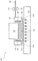
図7は、システムの様々な表面に対して非接触洗浄工程を実行するために、リソグラフィシステム又は他の半導体製造システムに組み込まれ得る静電洗浄モジュール700における実施例の概略図を示す。静電洗浄モジュール700は、静電相互作用を用いて構成620から粒子又は他の汚れを除去するよう設計される。図7に示された典型的な構成の通り、静電洗浄モジュール700は様々な板体(又は他の適当な特徴部)710,720,及び730を備える。板体720及び730は、導電性板体725及び735をそれぞれさらに備え得る。板体は、板体710と板体720との間に進入路を形成し、板体720と板体730との間に進出路を形成するよう設定される。上述した配置は、図示した洗浄されるべき構成620に隣接して位置され得る。正の高電圧が、構成620へ印加され、構成620上に付着する粒子740も帯電され得る。負の高電圧が導電性板体725及び735へ印加され得る。例えば帯電アルゴンなどの帯電ガス750は、板体710及び720間の進入路を経て導入及び通過される。構成620の表面を通り過ぎる時に、帯電ガス750は、構成620から粒子740を追い出す又は取り除き、板体720及び730間の進出路に移動し得る。負電荷を帯びた板体725及び735を通過する時に、帯電した粒子740は、帯電した板体725及び735と共に静電相互作用を受ける。帯電した粒子740は、帯電した板体によって中和され得る、すなわち導電性板体725及び735へ引きつけられ得る。静電洗浄モジュール700は、別な方法で異なって、効果的な洗浄及び最適化された機能のために設計されてもよい。例えば、構成620と導電性板体725及び735とは、逆に印加された高電圧を有し得る。帯電ガス750は、種々の構成次第で、負帯電又は正帯電の状態がもたらされ得る。
FIG. 7 shows a schematic diagram of an example of an
帯電ガス750は、帯電ガス噴出器,イオンシャワー,又は他の電荷発生器によって供給されてもよい(板体710及び720によって発生されてもよい)。イオン発生器は、粒子を誘起する静電放電(ESD)を除去するために、イオンを構成620へ直接届ける。
The charged
図8は、システムの様々な構成に対して洗浄工程を実行するために、リソグラフィシステム又は他の半導体製造システムに組み込まれ得る洗浄スクラバー(洗浄装置)800における実施例の概略図を示す。例えば、洗浄スクラバー800は、液浸リソグラフィシステムに内蔵されてもよい。洗浄スクラバー800は、洗浄ヘッド810を備える。洗浄ヘッド810は、スポンジ,繊維状ブラシ,又は他の適した構成で設計されてもよい。洗浄ヘッド810は、ポリエチレン(PE),ポリビニルアルコール(PVA),及びポリプロピレン(PP)から成る群から選択された材料を含み得る。洗浄ヘッド810は、洗浄流体を運ぶための移送路をさらに備え得る。
FIG. 8 shows a schematic diagram of an example of a cleaning scrubber (cleaning apparatus) 800 that can be incorporated into a lithography system or other semiconductor manufacturing system to perform a cleaning process on various configurations of the system. For example, the cleaning
洗浄スクラバー800は、洗浄ヘッド810を保持するよう設計されたホルダ820を備え得る。洗浄スクラバー800は、ホルダ820を固定するための連結装置830をさらに備え、洗浄ヘッド810の移送路へ連通する流体路を提供し、他の構成を保持するための構造を提供し得る。モータ840は、その軸(連結装置830の方向に沿う)周りの回転,軸に沿った振動,その軸に対して直行する一時的な振動(又は移動),又はそれらの組み合わせを含む様々なモードにおいて移動する洗浄ヘッドを駆動するために、連結装置830を備え一体化され得る。回転速度は、およそ1rpmから1000rpmまでにわたる範囲をとり得る。また、モータは、回転なしで静止したままである。軸に沿った振動は、およそ0.5Hzから5000Hzまでにわたる範囲の周波数を有し得る。一時的な振動は、およそ0.5Hzから5000Hzまでにわたる範囲の周波数を有し得る。洗浄スクラバー800は、洗浄流体へ超音波力を導入するために、一体化された超音波ユニット850をさらに備え得る。超音波ユニット850は、図1の超音波ユニット150の一つと同様であり得る。
The cleaning
洗浄スクラバー800は、様々な洗浄流体を供給するための洗浄流体供給器860を備える。例えば、洗浄流体供給器860は、種々の流体と制御流れオン/オフとその流速とをそれぞれ提供するために、複数の入口862a,862b,及び862cと、入口に関連付けられた複数のバルブ864a,864b,及び864cとを備えるよう設計されてもよい。このようにして、種々の流体は一定の比率で混合され得る、すなわち、単一の流体は、任意の時間中に流され、別の流体は様々な洗浄手法を実施するために他の時間中に流される。ある実施例においては、入口862aは、DIWを供給するために、DIW源へ接続されてもよい。入口862bは、第1の化学物質を供給するために、第1の化学物質源へ接続されてもよい。入口862cは、第2の化学物質を供給するために、第2の化学物質源へ接続されてもよい。様々な洗浄流体は、限定されないが、界面活性剤,溶媒,NH4OH,H2O2,O3,PGME/PGMEA(プロピレングリコールモノエチルエーテル/プロピレングリコールモノエチルエーテルアセテート),シクロヘキサノール,イソプロピルアルコール(IPA),アセトン,アルコール,モノエタノールアミン(MEA),及びこれらの組み合わせを含み得る。洗浄流体供給器860は、図1のヒータ170と同様の一乃至複数のヒータを備え、関連した流体を加熱するために構成されてもよい。
The cleaning
図9は、システムの様々な表面に対して洗浄工程を実行するために、リソグラフィシステム又は他の半導体製造システムに組み込まれる洗浄噴出器900における別の実施例の概略図を示す。例えば、洗浄噴出器900は、液浸リソグラフィシステムに内蔵されてもよい。洗浄噴出器900は、液浸リソグラフィシステムへ一体化され、基板テーブル上に配置され得る。洗浄噴出器900は、図6の噴出器610と同様の噴出ヘッドを備えるが、異なる洗浄手法を実施し異なる洗浄流体を用いるために異なって設計され得る。噴出圧力は、1気圧より高く設計され得る。洗浄噴出器900は、およそ0.1cc/secから200cc/secまでにわたる範囲の流速を有する洗浄流体を発射するよう設計され得る。
FIG. 9 shows a schematic diagram of another embodiment of a
洗浄噴出器900は、洗浄流体へ超音波エネルギーを導入する為に、それに一体化された超音波ユニット850を備え得る。洗浄噴出器900は、その周囲に流体パージドライノズルをさらに備え得る。洗浄噴出器900は、様々な洗浄流体を供給するために、洗浄流体供給器860を備える。例えば、洗浄流体供給器860は、種々の流体と制御流れオン/オフとその流速とをそれぞれ提供するため、様々な洗浄手法を実施するために、複数の入口862a,862b,及び862cと、関連付けられた複数のバルブ864a,864b,及び864cとを備えるよう設計されてもよい。洗浄流体供給器860は、図1のヒータ170と同様の一乃至複数のヒータを備え、関連した流体を加熱するために構成されてもよい。洗浄噴出器900は、噴出器が様々なモードにおいて移動可能であり、かつ予期されるどのような角度でも傾斜可能なように設計されたモータを備えてもよい。
The cleaning
図10は、図6乃至図9の洗浄ユニットの一つを一体的に有する洗浄モジュール1000において別の実施例の概略図を示す。洗浄モジュール1000は、例えば構成620などのシステムの様々な一部分に対して洗浄工程を実行するために、リソグラフィシステム又は他の半導体製造システムに組み込まれ得る。ある実施例においては、洗浄モジュール1000は、液浸リソグラフィシステムに内蔵されてもよい。
FIG. 10 shows a schematic diagram of another embodiment of the
洗浄モジュール1000は、洗浄用空間を取り囲む、洗浄溶液を供給する、使用された洗浄溶液を排液する、洗浄ユニットを保持する、及び例えばパージガスを供給するなど他の機能を実行するよう設計された洗浄フレーム1010を備える。洗浄フレーム1010は、洗浄及び/又は乾燥のためのパージガスを送出するために、そこに一体化されたパージガス送出システム1012を備え得る。パージガス送出システム1012は、工程作業圧力より高い圧力を有するパージガスを供給する。パージガスは、窒素,アルゴン,圧縮乾燥空気,及び他の適したガスを含み得る。パージガス送出システム1012は、パージガスを送出するための一乃至複数の開口部を有し得る。パージガスは、乾燥用の加熱空気をさらに供給するために、加熱構成部と接続されてもよい。洗浄フレーム1010は、洗浄流体,パージガス,及び/又は他の廃流体すなわち残留物を除去するために、吸引排液システム1014を備える。吸引排液システム1014は、負圧差により廃流体及び/又はパージガスが引き離すことができるように、工程作業圧力より低い圧力を有し得る。吸引排液システム1014は、排液効果を最大限にすることを目的として設定された一乃至複数の開口部を有し得る。
The
洗浄モジュール1000は、それに一体化された洗浄ユニット1020を備える。洗浄ユニット1020は、図8の洗浄スクラバー800,図9の洗浄噴出器900,それらの組み合わせ,又は他の適した洗浄装置であってもよい。例として図示された洗浄ユニット1020は、構成,動作,及び用途という点では、図8の洗浄スクラバー800と同様の洗浄スクラバーである。
The
別の例においては、洗浄スクラバー800及び噴出器900は、様々な構成に結合され、例えば図11に概略図として例示された洗浄モジュール1100などの洗浄フレーム1010と一体化され得る。洗浄モジュール1100は、洗浄スクラバー800と、洗浄スクラバーの両側に配置された2つの噴出器900とを備える。様々な洗浄ユニット800及び900は、1つの共通の洗浄流体供給器860を共有するよう結合され得る。共通の洗浄流体供給器860は、洗浄流体を加熱するために、それに組み込まれるヒータをさらに具備してもよい。
In another example, the cleaning
図12a及び図12cを参照すると、洗浄モジュール1210は、一乃至複数の図10の洗浄モジュール1000又は図11の洗浄モジュール1100と同様である。洗浄モジュールは、関連システムの様々な構成を洗浄するために、リソグラフィシステム,特に液浸リソグラフィシステム,又は半導体ウエハ製造装置と一体化されてもよい。例えば、洗浄モジュール1210は、図12aに示した液浸流体保持モジュール130,図12bに示したレンズシステム120,及び/又はそこにウエハ1220が配置され得る基板テーブル110を洗浄するために、利用され得る。洗浄モジュール1210は、種々のパターンで移動可能となるよう設計され得る。例えば、洗浄モジュール1210が、図13a,13b,及び13cに示した様々なパターンで移動し得る。
Referring to FIGS. 12a and 12c, the
図14a及び図14bは、図8の洗浄スクラバー800又は他の適した洗浄ユニットを洗浄するための自己洗浄システム及び方法における様々な実施例の概略図を示す。図14aに示された自己洗浄システムは、その中が洗浄溶液1420で満たされた洗浄タンク1410を備える。洗浄タンク1410は、洗浄溶液1420を供給するために、例えば化学物質入口1412などの他の特徴部を備える場合があり、有効的な洗浄効果を目的として洗浄溶液を十分に攪拌するために、内蔵して超音波ユニットをさらに備えてもよい。その上、洗浄タンク1410は、タンクに内蔵されるヒータを備えてもよい。洗浄スクラバー800の洗浄ヘッド810は、洗浄用の洗浄溶液1420に完全に浸され得る。洗浄溶液1420は、SC1,SC2,ピランハ溶液,H2O2,又はオゾン水,NH4OH/H2O2/H2O,又は他の適当な化学溶液を含み得る。
14a and 14b show schematic diagrams of various embodiments of a self-cleaning system and method for cleaning the
図14bに示す機構は、洗浄タンク1430と、洗浄用の洗浄スクラバー800へ洗浄溶液を発射するよう構成された噴出器900とを備える。この2つの自己洗浄システムは、様々な洗浄モジュールに組み込まれ、さらに様々な半導体製造装置に組み込まれた洗浄スクラバーを洗浄及び整備するために、二者択一的に又は共同で利用され得る。第1又は第2の自己洗浄システムは、洗浄スクラバー800の一部として備えられ得る。
The mechanism shown in FIG. 14b includes a
図1乃至図11に図示された洗浄ユニット又は洗浄モジュールにおける種々の実施例は、一体化された洗浄ユニット又は洗浄モジュールを具備する半導体製造装置の例としての役割を果たすだけである。これらの例は、限定を意図するものではない。様々な組み合わせ及び/又は変更が、異なる用途及び製造システムに適用され得る。 Various embodiments of the cleaning unit or cleaning module illustrated in FIGS. 1 to 11 serve only as an example of a semiconductor manufacturing apparatus having an integrated cleaning unit or cleaning module. These examples are not intended to be limiting. Various combinations and / or modifications may be applied to different applications and manufacturing systems.
図15は、一体化された洗浄モジュールを用いて半導体製造装置を洗浄するためのある典型的な方法1500のフローチャートを提供する。方法1500は、一体化された洗浄モジュールを具備する半導体製造装置を準備することにより、ステップ1502で始まり得る。半導体製造装置は、液浸リソグラフィシステム,又は代わりにドライリソグラフィシステム,又は例えば物理気相蒸着(スパッタリング)システム,又は化学気相蒸着システムなどの半導体製造装置であってもよい。洗浄モジュールは、図1乃至図5に示された様々な実施例に構成された超音波ユニットを備え得る。洗浄モジュールは、液浸流体保持モジュールと一体であってもよく、別個のモジュールであってもよい。洗浄モジュールは、例えば図6乃至図9に示されたものなど、洗浄スクラバー,噴出器,液体ガスを使用する噴出器,静電洗浄器,超音波ユニット,またはそれらの組み合わせを含む他の洗浄ユニットを備え得る。洗浄モジュールは、それぞれ、例えば、図10及び図11の洗浄モジュール1000又は1100であってもよい。
FIG. 15 provides a flowchart of one
ステップ1504では、洗浄流体は、洗浄モジュールを通じて供給され、洗浄流体は、DIW,界面活性剤,溶媒,NH4OH,H2O2,O3,PGME/PGMEA(プロピレングリコールモノメチルエーテル/プロピレングリコールモノメチルエーテルアセテート),シクロヘキサノール,イソプロピルアルコール(IPA),アセトン,アルコール,モノエタノールアミン(MEA)及びそれらの組み合わせを含み得る。洗浄流体は、およそ20℃から70℃までにわたる範囲の温度を有し得る。典型的な洗浄流体は、H2O2,又はオゾン水を含み得る。別の典型的な洗浄流体は、NH4OH/H2O2/H2Oを含み得る。
In
ステップ1506では、方法1500は、例えばレンズ,基板テーブル,及び/又は液浸リソグラフィシステムにおける液浸流体保持モジュールの洗浄など半導体洗浄装置の構成を洗浄するために、洗浄工程を実行する。洗浄されるべきその他の典型的な構成は、ウエハロボット又は処理チャンバーの壁を含み得る。洗浄工程中に、洗浄モジュールは、種々のパターンで移動し得る。洗浄モジュールにおける種々の機構又は機能は、同期的に作動し一緒に機能し得る。例えば、超音波エネルギー及び/又は加熱エネルギーが、異なる洗浄用途のための様々な洗浄手法に従う洗浄溶液へ導入されてもよい。ステップ1504及び1506は、洗浄工程を実行するために、組み合わされ得る。洗浄工程は、およそ0.5秒から30分までにわたる範囲の継続時間を有し得る。方法1500は、洗浄工程の後にDIW洗い流し工程を実行してもよい。
In
方法1500は、前工程で洗浄された表面(又は構成)に対して乾燥工程を実行するために、ステップ1508を続行する。乾燥工程1508は、洗浄モジュールを通じたパージガスの送出を含む。パージガスは、アルゴン,窒素,又は他の適したガスを含み得る。乾燥工程は、二者択一的に又は共同で、例えばIPAなどの他の液体を用いて実施され得る。乾燥工程は、洗浄流体を引き込むために、吸引構成部を用いて構成してもよい。
The
ステップ1510では、洗浄が完了した後、例えば液浸リソグラフィ露光,ドライリソグラフィ露光,薄膜蒸着,又は関連システムにおいて実施可能な他の工程などの標準的な半導体工程のために、例えば半導体ウエハなどの基板が基板テーブル上に搭載され配置され得る。ステップ1504からステップ1508までの洗浄工程は、用具整備のための所定のスケジュールで、又は特定のウエハ数が処理済みになった後、又は他の検査データ,テストデータ,及び/又は認定データが所定の悪化を示す時に、実施される。
In
このようにして、本開示内容は、リソグラフィ装置を提供する。前記装置は、結像レンズモジュールと、結像レンズモジュールの下方に配置され基板を保持するよう構成された基板テーブルと、リソグラフィ装置の洗浄に適合された洗浄モジュールとを備え、洗浄モジュールは、超音波ユニット,スクラバー,流体噴出器,静電洗浄器,及びそれらの組み合わせから成る群から選択されたものである。 Thus, the present disclosure provides a lithographic apparatus. The apparatus comprises an imaging lens module, a substrate table disposed below the imaging lens module and configured to hold a substrate, and a cleaning module adapted for cleaning a lithographic apparatus, the cleaning module comprising: One selected from the group consisting of sonic units, scrubbers, fluid jets, electrostatic cleaners, and combinations thereof.
前記装置は、結像レンズモジュールと基板テーブル上の基板との間の空間へ液浸流体を供給するよう構成された液浸流体保持モジュールをさらに備え得る。洗浄モジュールは、結像レンズ,基板テーブル,及び/又は液浸流体保持モジュールのうち少なくとも一つを洗浄するよう作動可能であり得る。洗浄モジュールは、液浸流体保持モジュール及び基板テーブルのうち少なくとも一つと一体化され得る。洗浄モジュールは、ロボットと一体化され得る。洗浄モジュールは、回転,振動,水平動作,及びそれらの組み合わせから成る群から選択されたモードで移動するよう構成され得る。洗浄モジュールは、洗浄モジュールで使用するための洗浄流体を供給するために、洗浄流体入口を備え得る。洗浄流体は、液浸流体,化学溶液,パージガスから成る群から選択されたものであり得る。洗浄流体は、界面活性剤,溶媒,NH4OH,H2O2,O3,PGME/PGMEA,シクロヘキサノール,イソプロピルアルコール(IPA),アセトン,アルコール,及びMEAから成る群から選択された材料を含み得る。洗浄モジュールは、洗浄流体を引き込むよう構成された吸引構成部を備え得る。超音波ユニットは、洗浄流体へ超音波エネルギーを供給するよう適合され得る。スクラバーは、スポンジとブラシとから選択されたものであり得る。スクラバーは、ポリエチレン(PE),ポリビニルアルコール(PVA),及びポリプロピレン(PP)から成る群から選択された材料を含み得る。流体噴出器は、様々な圧力,角度,及び動作で作動可能なものであり得る。流体噴出器は、洗浄用の液体ガスを使用するよう構成され得る。 The apparatus may further comprise an immersion fluid holding module configured to supply immersion fluid to a space between the imaging lens module and the substrate on the substrate table. The cleaning module may be operable to clean at least one of the imaging lens, the substrate table, and / or the immersion fluid holding module. The cleaning module may be integrated with at least one of the immersion fluid holding module and the substrate table. The cleaning module can be integrated with the robot. The cleaning module may be configured to move in a mode selected from the group consisting of rotation, vibration, horizontal motion, and combinations thereof. The cleaning module may include a cleaning fluid inlet for supplying cleaning fluid for use in the cleaning module. The cleaning fluid may be selected from the group consisting of an immersion fluid, a chemical solution, and a purge gas. The cleaning fluid is a material selected from the group consisting of surfactants, solvents, NH 4 OH, H 2 O 2 , O 3 , PGME / PGMEA, cyclohexanol, isopropyl alcohol (IPA), acetone, alcohol, and MEA. May be included. The cleaning module may comprise a suction component configured to draw cleaning fluid. The ultrasonic unit may be adapted to supply ultrasonic energy to the cleaning fluid. The scrubber can be selected from a sponge and a brush. The scrubber may comprise a material selected from the group consisting of polyethylene (PE), polyvinyl alcohol (PVA), and polypropylene (PP). The fluid ejector can be operable at various pressures, angles, and movements. The fluid ejector may be configured to use a cleaning liquid gas.
また、本開示内容は、液浸リソグラフィ装置をも提供する。前記装置は、結像レンズモジュールと、結像レンズの下方に配置され基板を固定するよう構成された基板テーブルと、結像レンズモジュールとステージ上の基板との間の空間へ流体を供給するよう構成された流体モジュールと、液浸リソグラフィ装置を洗浄するために超音波エネルギーを供給するよう構成された超音波モジュールとを備える。 The present disclosure also provides an immersion lithographic apparatus. The apparatus supplies fluid to a space between the imaging lens module, a substrate table disposed below the imaging lens and configured to secure the substrate, and a space between the imaging lens module and the substrate on the stage. A fluid module configured and an ultrasound module configured to supply ultrasound energy to clean the immersion lithographic apparatus.
前記装置において、超音波モジュールは、ステージ及び/又は流体モジュールに内蔵され得る。超音波モジュールは、洗浄を最も効果的にするための動作が可能であり得る。超音波モジュールは複数の超音波ユニットを備え得る。超音波モジュールは、およそ1ミリワットから1キロワットまでにわたる範囲の力と、およそ1KHzから1GHzまでにわたる範囲の周波数とで超音波エネルギーを供給するよう作動可能であり得る。超音波モジュールは、洗浄流体へ超音波エネルギーを供給するよう適合され得る。流体モジュールは、純水,洗浄化学物質,窒素ガス,アルゴンガス,及びそれらの組み合わせから成る群から選択された流体を供給するよう構成され得る。流体モジュールは、固体表面と接触してその上でガスへ変化する液体ガスを供給するよう構成され得る。液体ガスは、窒素とアルゴンとから成る群から選択されたものであり得る。流体モジュールは、0℃以下の温度で液体ガスを供給するよう構成され得る。 In the apparatus, the ultrasonic module may be incorporated in the stage and / or the fluid module. The ultrasound module may be capable of operation to make cleaning most effective. The ultrasound module may comprise a plurality of ultrasound units. The ultrasound module may be operable to deliver ultrasound energy at a power ranging from approximately 1 milliwatt to 1 kilowatt and a frequency ranging from approximately 1 KHz to 1 GHz. The ultrasonic module may be adapted to supply ultrasonic energy to the cleaning fluid. The fluid module may be configured to supply a fluid selected from the group consisting of pure water, cleaning chemicals, nitrogen gas, argon gas, and combinations thereof. The fluid module may be configured to supply a liquid gas that contacts the solid surface and changes to a gas thereon. The liquid gas may be selected from the group consisting of nitrogen and argon. The fluid module may be configured to supply liquid gas at a temperature below 0 ° C.
また、本開示内容は、方法も提供する。この方法は、スクラバー,流体噴出器,超音波ユニット,及び静電洗浄器のうち少なくとも一つを備えた洗浄モジュールを具備するリソグラフィ装置の準備と、洗浄モジュールを利用することによるリソグラフィ装置に対する洗浄工程の実行と、結像層で表面を覆われた基板に対する露光工程の実行とを含む。洗浄工程の実行は、液浸流体,化学溶液,液体ガス,及びパージガスから成る群から選択された洗浄流体の利用を含み得る。洗浄工程の実行は、界面活性剤,溶媒,NH4OH,H2O2,O3,PGME/PGMEA,シクロヘキサノール,イソプロピルアルコール(IPA),アセトン,アルコール,及びMEAから成る群から選択された材料を有する洗浄流体の利用を含み得る。洗浄工程の実行は、結像レンズ,基板テーブル,及びリソグラフィ装置の流体モジュールのうち少なくとも一つを洗浄することを含み得る。洗浄工程の実行は、乾燥手順を含み得る。前記方法は、露光工程の実行前に結像レンズと基板との間の空間の間で液浸流体を分注(調合)することをさらに含み得る。露光工程の実行は、半導体ウエハの露光を含み得る。 The present disclosure also provides a method. The method comprises the preparation of a lithographic apparatus comprising a cleaning module comprising at least one of a scrubber, a fluid ejector, an ultrasonic unit, and an electrostatic cleaner, and a cleaning process for the lithographic apparatus using the cleaning module And performing an exposure process on a substrate whose surface is covered with an imaging layer. Performing the cleaning process may include utilizing a cleaning fluid selected from the group consisting of immersion fluid, chemical solution, liquid gas, and purge gas. The performance of the cleaning step was selected from the group consisting of surfactant, solvent, NH 4 OH, H 2 O 2 , O 3 , PGME / PGMEA, cyclohexanol, isopropyl alcohol (IPA), acetone, alcohol, and MEA. The use of a cleaning fluid with material may be included. Performing the cleaning process may include cleaning at least one of the imaging lens, the substrate table, and the fluid module of the lithographic apparatus. Performing the washing step can include a drying procedure. The method may further include dispensing an immersion fluid between the space between the imaging lens and the substrate prior to performing the exposure step. Execution of the exposure process can include exposure of the semiconductor wafer.
前述のものは、当業者がその後の詳細な説明をよく理解し得るように、いくつかの実施例の特徴を概説している。当業者は、彼らが、同じ目的を達成する及び/又はここで紹介された実施例の同じ効果を果たすために、他の工程及び構造の設計又は変更の基礎として本開示内容をすぐに利用し得ることを理解すべきである。また、当業者は、このような同等の構成が本開示内容の技術的思想と適用範囲を逸脱せず、彼らが本開示内容の技術的思想と適用範囲を逸脱しないで様々な変更,置換及び改変をなし得ることを、明確に理解すべきである。 The foregoing has outlined features of some embodiments so that those skilled in the art may better understand the detailed description that follows. Those skilled in the art will readily use the present disclosure as a basis for the design or modification of other processes and structures to achieve the same objectives and / or to achieve the same effects of the embodiments introduced herein. It should be understood that you get. Moreover, those skilled in the art will recognize that such an equivalent configuration does not depart from the technical idea and scope of the present disclosure, and that various modifications, substitutions and substitutions can be made without departing from the technical idea and scope of the present disclosure. It should be clearly understood that modifications can be made.
100,200 液浸リソグラフィシステム
110 基板テーブル
120 レンズシステム
130 液浸流体保持モジュール
132a,132b,134,136 開口部
150 超音波ユニット
160,210,210a 洗浄流体供給器
170 ヒーター
220,220a 洗浄流体排液器
300,400,500 リソグラフィシステム
310,410,510 分離洗浄モジュール
610 噴出器
620 構成
630 ガス,液体
640,740 粒子
700 静電洗浄モジュール
710,720,730 板体
725,735 導電性板体
750 帯電ガス,粒子
800 洗浄スクラバー
810 洗浄ヘッド
820 ホルダ
830 連結装置
840 モータ
850 超音波ユニット
860 洗浄流体供給器
862a,862b,862c 入口
864a,864b,864c バルブ
900 洗浄噴出器
1000,1100,1210 洗浄モジュール
1010 洗浄フレーム
1012 パージガス送出システム
1014 吸引排液システム
1020 洗浄ユニット
1220 ウエハ
1410,1430 洗浄タンク
1412 化学物質入口
1420 洗浄溶液
1500 方法
1502,1504,1506,1508,1510 ステップ
100, 200 immersion lithography system
110 substrate table
120 lens system
130 Immersion fluid retention module
132a, 132b, 134, 136 opening
150 Ultrasonic unit
160, 210, 210a Cleaning fluid supplier
170 heater
220, 220a Cleaning fluid drainer
300, 400, 500 Lithography system
310, 410, 510 Separate cleaning module
610 ejector
620 configuration
630 Gas, liquid
640,740 particles
700 electrostatic cleaning module
710, 720, 730 plate
725,735 Conductive plate
750 Charged gas, particles
800 cleaning scrubber
810 Cleaning head
820 holder
830 coupling device
840 motor
850 ultrasonic unit
860 Cleaning fluid supply
862a, 862b, 862c Entrance
864a, 864b, 864c Valve
900 cleaning spray
1000, 1100, 1210 Cleaning module
1010 Cleaning frame
1012 Purge gas delivery system
1014 Suction drainage system
1020 Cleaning unit
1220 wafer
1410, 1430 Cleaning tank
1412 Chemical substance inlet
1420 Cleaning solution
1500 methods
1502, 1504, 1506, 1508, 1510 steps
Claims (15)
前記結像レンズモジュールの下方に配置され基板を保持するよう構成された基板テーブルと、
リソグラフィ装置の洗浄に適合された洗浄モジュールとを備え、
前記洗浄モジュールは、
第一の板体と、
第一の導電性板体を備え、前記第一の板体から間隔をあけて配置された第二の板体と、
第二の導電性板体を備え、前記第二の板体から間隔をあけて配置された第三の板体と、
前記第一の板体と前記第二の板体との間の進入路と、
前記第二の板体と前記第三の板体との間の進出路とを備え、
前記第一の導電性板体と前記第二の導電性板体は、第一の電圧を印加することを特徴とするリソグラフィ装置。 An imaging lens module;
A substrate table constructed to hold a substrate disposed below the imaging lens module,
A cleaning module adapted for cleaning a lithographic apparatus,
The cleaning module includes:
The first plate,
A second plate comprising a first conductive plate, spaced from the first plate, and
A third plate comprising a second conductive plate, spaced from the second plate, and
An approach path between the first plate and the second plate;
An advancing path between the second plate and the third plate,
The lithographic apparatus, wherein the first conductive plate and the second conductive plate are applied with a first voltage .
第一の導電性板体を備え、前記第一の板体から間隔をあけて配置された第二の板体と、
第二の導電性板体を備え、前記第二の板体から間隔をあけて配置された第三の板体と、
前記第一の板体と前記第二の板体との間の進入路と、
前記第二の板体と前記第三の板体との間の進出路とを備えた洗浄モジュールとを具備するリソグラフィ装置の準備と、
前記洗浄モジュールを利用することによる前記リソグラフィ装置に対する洗浄工程の実行と、
結像層で表面を覆われた基板に対する露光工程の実行と
から構成されることを特徴とする方法。 The first plate,
A second plate comprising a first conductive plate, spaced from the first plate, and
A third plate comprising a second conductive plate, spaced from the second plate, and
An approach path between the first plate and the second plate;
A lithographic apparatus comprising a cleaning module comprising an advancing path between the second plate and the third plate;
Performing a cleaning step on the lithographic apparatus by utilizing the cleaning module;
Wherein the composed of the execution of the exposure process for the substrate covered the surface with the imaging layer.
前記第一の導電性板体と前記第二の導電性板体に第一の電圧を印加し、Applying a first voltage to the first conductive plate and the second conductive plate,
前記リソグラフィ装置の洗浄されるべき構成に第二の電圧を印加し、Applying a second voltage to the structure to be cleaned of the lithographic apparatus;
前記洗浄されるべき構成の表面に、前記進入路を経て通過する帯電ガスを導入し、Introducing a charged gas that passes through the approach path into the surface of the configuration to be cleaned;
前記帯電ガスを利用して、前記洗浄されるべき構成から前記進出路へ、前記洗浄されるべき構成に付着する粒子を追い出すことUsing the charged gas, the particles adhering to the configuration to be cleaned are expelled from the configuration to be cleaned to the advance path.
から構成される請求項9記載の方法。The method of claim 9 comprising:
前記第一の導電性板体と前記第二の導電性板体に第一の電圧を印加し、Applying a first voltage to the first conductive plate and the second conductive plate,
前記リソグラフィ装置の洗浄されるべき構成に第二の電圧を印加し、Applying a second voltage to the structure to be cleaned of the lithographic apparatus;
前記洗浄されるべき構成の表面に、前記進入路を経て通過する帯電ガスを導入し、Introducing a charged gas that passes through the approach path into the surface of the configuration to be cleaned;
前記帯電ガスを利用して、前記洗浄されるべき構成から前記進出路へ、前記洗浄されるべき構成に付着する粒子を取り除くことUsing the charged gas, particles adhering to the structure to be cleaned are removed from the structure to be cleaned to the advance path.
から構成される請求項9記載の方法。The method of claim 9 comprising:
Applications Claiming Priority (2)
| Application Number | Priority Date | Filing Date | Title |
|---|---|---|---|
| US72956505P | 2005-10-24 | 2005-10-24 | |
| US11/427,421 US7986395B2 (en) | 2005-10-24 | 2006-06-29 | Immersion lithography apparatus and methods |
Publications (2)
| Publication Number | Publication Date |
|---|---|
| JP2007123882A JP2007123882A (en) | 2007-05-17 |
| JP4532455B2 true JP4532455B2 (en) | 2010-08-25 |
Family
ID=37726774
Family Applications (1)
| Application Number | Title | Priority Date | Filing Date |
|---|---|---|---|
| JP2006287405A Active JP4532455B2 (en) | 2005-10-24 | 2006-10-23 | Immersion lithography apparatus and method |
Country Status (7)
| Country | Link |
|---|---|
| US (1) | US7986395B2 (en) |
| EP (1) | EP1777589B1 (en) |
| JP (1) | JP4532455B2 (en) |
| KR (1) | KR100823664B1 (en) |
| DE (1) | DE602006014341D1 (en) |
| SG (2) | SG131829A1 (en) |
| TW (1) | TWI342987B (en) |
Families Citing this family (60)
| Publication number | Priority date | Publication date | Assignee | Title |
|---|---|---|---|---|
| TWI245163B (en) | 2003-08-29 | 2005-12-11 | Asml Netherlands Bv | Lithographic apparatus and device manufacturing method |
| US8040489B2 (en) * | 2004-10-26 | 2011-10-18 | Nikon Corporation | Substrate processing method, exposure apparatus, and method for producing device by immersing substrate in second liquid before immersion exposure through first liquid |
| US20070242248A1 (en) * | 2004-10-26 | 2007-10-18 | Nikon Corporation | Substrate processing method, exposure apparatus, and method for producing device |
| US7880860B2 (en) | 2004-12-20 | 2011-02-01 | Asml Netherlands B.V. | Lithographic apparatus and device manufacturing method |
| EP1909310A4 (en) * | 2005-07-11 | 2010-10-06 | Nikon Corp | Exposure apparatus and method for manufacturing device |
| JP5036996B2 (en) * | 2005-10-31 | 2012-09-26 | 東京応化工業株式会社 | Cleaning liquid and cleaning method |
| US8125610B2 (en) * | 2005-12-02 | 2012-02-28 | ASML Metherlands B.V. | Method for preventing or reducing contamination of an immersion type projection apparatus and an immersion type lithographic apparatus |
| CN102298274A (en) * | 2006-05-18 | 2011-12-28 | 株式会社尼康 | Exposure method and apparatus, maintenance method and device manufacturing method |
| US7969548B2 (en) * | 2006-05-22 | 2011-06-28 | Asml Netherlands B.V. | Lithographic apparatus and lithographic apparatus cleaning method |
| JP2008004928A (en) * | 2006-05-22 | 2008-01-10 | Nikon Corp | Exposure method and apparatus, maintenance method, and device manufacturing method |
| EP2034515A4 (en) * | 2006-05-23 | 2012-01-18 | Nikon Corp | Maintenance method, exposure method and apparatus, and device manufacturing method |
| US8564759B2 (en) * | 2006-06-29 | 2013-10-22 | Taiwan Semiconductor Manufacturing Company, Ltd. | Apparatus and method for immersion lithography |
| JP5245825B2 (en) * | 2006-06-30 | 2013-07-24 | 株式会社ニコン | Maintenance method, exposure method and apparatus, and device manufacturing method |
| WO2008026593A1 (en) * | 2006-08-30 | 2008-03-06 | Nikon Corporation | Exposure apparatus, device production method, cleaning method, and cleaning member |
| KR20090060270A (en) * | 2006-09-08 | 2009-06-11 | 가부시키가이샤 니콘 | Cleaning member, cleaning method and device manufacturing method |
| US8253922B2 (en) | 2006-11-03 | 2012-08-28 | Taiwan Semiconductor Manufacturing Company, Ltd. | Immersion lithography system using a sealed wafer bath |
| US8208116B2 (en) * | 2006-11-03 | 2012-06-26 | Taiwan Semiconductor Manufacturing Company, Ltd. | Immersion lithography system using a sealed wafer bath |
| WO2008089990A2 (en) * | 2007-01-26 | 2008-07-31 | Carl Zeiss Smt Ag | Method for operating an immersion lithography apparatus |
| US8654305B2 (en) * | 2007-02-15 | 2014-02-18 | Asml Holding N.V. | Systems and methods for insitu lens cleaning in immersion lithography |
| US8817226B2 (en) | 2007-02-15 | 2014-08-26 | Asml Holding N.V. | Systems and methods for insitu lens cleaning using ozone in immersion lithography |
| US7866330B2 (en) * | 2007-05-04 | 2011-01-11 | Asml Netherlands B.V. | Cleaning device, a lithographic apparatus and a lithographic apparatus cleaning method |
| US8947629B2 (en) * | 2007-05-04 | 2015-02-03 | Asml Netherlands B.V. | Cleaning device, a lithographic apparatus and a lithographic apparatus cleaning method |
| US9013672B2 (en) * | 2007-05-04 | 2015-04-21 | Asml Netherlands B.V. | Cleaning device, a lithographic apparatus and a lithographic apparatus cleaning method |
| US8011377B2 (en) * | 2007-05-04 | 2011-09-06 | Asml Netherlands B.V. | Cleaning device and a lithographic apparatus cleaning method |
| JP2009033111A (en) * | 2007-05-28 | 2009-02-12 | Nikon Corp | Exposure device, device manufacturing method, cleaning device, and cleaning method and exposure method |
| US20080304025A1 (en) * | 2007-06-08 | 2008-12-11 | Taiwan Semiconductor Manufacturing Company, Ltd. | Apparatus and method for immersion lithography |
| JP5018277B2 (en) * | 2007-07-02 | 2012-09-05 | 株式会社ニコン | Exposure apparatus, device manufacturing method, and cleaning method |
| US20090014030A1 (en) * | 2007-07-09 | 2009-01-15 | Asml Netherlands B.V. | Substrates and methods of using those substrates |
| US20090025753A1 (en) * | 2007-07-24 | 2009-01-29 | Asml Netherlands B.V. | Lithographic Apparatus And Contamination Removal Or Prevention Method |
| US7916269B2 (en) * | 2007-07-24 | 2011-03-29 | Asml Netherlands B.V. | Lithographic apparatus and contamination removal or prevention method |
| NL1035942A1 (en) * | 2007-09-27 | 2009-03-30 | Asml Netherlands Bv | Lithographic Apparatus and Method of Cleaning a Lithographic Apparatus. |
| SG151198A1 (en) * | 2007-09-27 | 2009-04-30 | Asml Netherlands Bv | Methods relating to immersion lithography and an immersion lithographic apparatus |
| JP5017232B2 (en) * | 2007-10-31 | 2012-09-05 | エーエスエムエル ネザーランズ ビー.ブイ. | Cleaning apparatus and immersion lithography apparatus |
| WO2009059614A1 (en) * | 2007-11-06 | 2009-05-14 | Carl Zeiss Smt Ag | Method for removing a contamination layer from an optical surface, method for generating a cleaning gas, and corresponding cleaning and cleaning... |
| NL1036273A1 (en) * | 2007-12-18 | 2009-06-19 | Asml Netherlands Bv | Lithographic apparatus and method of cleaning a surface or an immersion lithographic apparatus. |
| NL1036306A1 (en) | 2007-12-20 | 2009-06-23 | Asml Netherlands Bv | Lithographic apparatus and in-line cleaning apparatus. |
| US8339572B2 (en) | 2008-01-25 | 2012-12-25 | Asml Netherlands B.V. | Lithographic apparatus and device manufacturing method |
| US20100039628A1 (en) * | 2008-03-19 | 2010-02-18 | Nikon Corporation | Cleaning tool, cleaning method, and device fabricating method |
| NL1036709A1 (en) | 2008-04-24 | 2009-10-27 | Asml Netherlands Bv | Lithographic apparatus and a method of operating the apparatus. |
| TW201009895A (en) * | 2008-08-11 | 2010-03-01 | Nikon Corp | Exposure apparatus, maintaining method and device fabricating method |
| JP2010093245A (en) * | 2008-10-07 | 2010-04-22 | Nikon Corp | Exposure apparatus, maintenance method, exposure method, and device manufacturing method |
| NL2003421A (en) * | 2008-10-21 | 2010-04-22 | Asml Netherlands Bv | Lithographic apparatus and a method of removing contamination. |
| NL2005610A (en) | 2009-12-02 | 2011-06-06 | Asml Netherlands Bv | Lithographic apparatus and surface cleaning method. |
| MX2012007581A (en) * | 2009-12-28 | 2012-07-30 | Pioneer Hi Bred Int | Sorghum fertility restorer genotypes and methods of marker-assisted selection. |
| JP5402664B2 (en) * | 2010-01-19 | 2014-01-29 | 株式会社ニコン | Cleaning method, exposure apparatus, and device manufacturing method |
| US20120019803A1 (en) * | 2010-07-23 | 2012-01-26 | Nikon Corporation | Cleaning method, liquid immersion member, immersion exposure apparatus, device fabricating method, program, and storage medium |
| CA2856196C (en) | 2011-12-06 | 2020-09-01 | Masco Corporation Of Indiana | Ozone distribution in a faucet |
| JP2012195606A (en) * | 2012-06-13 | 2012-10-11 | Nikon Corp | Exposure device, device manufacturing method, and cleaning method |
| JP5302450B2 (en) * | 2012-09-20 | 2013-10-02 | カール・ツァイス・エスエムティー・ゲーエムベーハー | Method for removing a contamination layer from an optical surface, method for generating a cleaning gas, and corresponding cleaning and cleaning gas generation structure |
| CN108463437B (en) | 2015-12-21 | 2022-07-08 | 德尔塔阀门公司 | Fluid delivery system comprising a disinfection device |
| US10866516B2 (en) | 2016-08-05 | 2020-12-15 | Taiwan Semiconductor Manufacturing Co., Ltd. | Metal-compound-removing solvent and method in lithography |
| US10622211B2 (en) | 2016-08-05 | 2020-04-14 | Taiwan Semiconductor Manufacturing Co., Ltd. | Metal-compound-removing solvent and method in lithography |
| GB2562081B (en) | 2017-05-04 | 2020-07-15 | Imrali Ahmet | Slide cleaner |
| CN110352100A (en) * | 2017-07-14 | 2019-10-18 | 应用材料公司 | The method of component for cleaning material sedimentary origin, for the method for manufacture material sedimentary origin and the equipment of the component for cleaning material sedimentary origin |
| JP6942562B2 (en) * | 2017-08-25 | 2021-09-29 | キヤノン株式会社 | Lithography equipment and manufacturing method of goods |
| KR102008243B1 (en) * | 2017-09-07 | 2019-08-07 | 한국기계연구원 | Droplet ultrasonic cleaning apparatus of large surface and that method |
| CN111316168B (en) | 2017-10-31 | 2022-04-01 | Asml荷兰有限公司 | Metrology apparatus, method of measuring a structure, device manufacturing method |
| JP7186230B2 (en) | 2017-12-28 | 2022-12-08 | エーエスエムエル ネザーランズ ビー.ブイ. | Apparatus and method for removing contaminant particles from apparatus components |
| US10687410B2 (en) * | 2018-07-27 | 2020-06-16 | Taiwan Semiconductor Manufacturing Co., Ltd. | Extreme ultraviolet radiation source and cleaning method thereof |
| US11506985B2 (en) * | 2019-04-29 | 2022-11-22 | Taiwan Semiconductor Manufacturing Co., Ltd. | Semiconductor apparatus and method of operating the same for preventing photomask particulate contamination |
Citations (3)
| Publication number | Priority date | Publication date | Assignee | Title |
|---|---|---|---|---|
| WO2004105107A1 (en) * | 2003-05-23 | 2004-12-02 | Nikon Corporation | Exposure device and device manufacturing method |
| JP2005072404A (en) * | 2003-08-27 | 2005-03-17 | Sony Corp | Aligner and manufacturing method of semiconductor device |
| WO2005031820A1 (en) * | 2003-09-26 | 2005-04-07 | Nikon Corporation | Projection exposure apparatus, cleaning and maintenance methods of projection exposure apparatus, and method of producing device |
Family Cites Families (36)
| Publication number | Priority date | Publication date | Assignee | Title |
|---|---|---|---|---|
| US4509852A (en) * | 1980-10-06 | 1985-04-09 | Werner Tabarelli | Apparatus for the photolithographic manufacture of integrated circuit elements |
| JPS57153433A (en) * | 1981-03-18 | 1982-09-22 | Hitachi Ltd | Manufacturing device for semiconductor |
| GB2243269B (en) * | 1990-04-19 | 1994-04-13 | British Broadcasting Corp | Decoding binary-coded transmissions |
| US5132560A (en) * | 1990-09-28 | 1992-07-21 | Siemens Corporate Research, Inc. | Voltage comparator with automatic output-level adjustment |
| JPH05308497A (en) * | 1992-04-30 | 1993-11-19 | Konica Corp | Image forming device |
| US6169765B1 (en) * | 1997-05-28 | 2001-01-02 | Integration Associates, Inc. | Apparatus and method for output signal pulse width error correction in a communications receiver |
| AU1175799A (en) * | 1997-11-21 | 1999-06-15 | Nikon Corporation | Projection aligner and projection exposure method |
| KR20000009326U (en) * | 1998-11-02 | 2000-06-05 | 김영환 | Foreign material removal device of wafer chuck for exposure apparatus |
| WO2000074118A1 (en) * | 1999-05-27 | 2000-12-07 | Nikon Corporation | Exposure system, method of manufacturing device, and method of environmental control of exposure system |
| US6232796B1 (en) * | 1999-07-21 | 2001-05-15 | Rambus Incorporated | Apparatus and method for detecting two data bits per clock edge |
| DE10061248B4 (en) * | 2000-12-09 | 2004-02-26 | Carl Zeiss | Method and device for in-situ decontamination of an EUV lithography device |
| US6724460B2 (en) * | 2001-11-19 | 2004-04-20 | Asml Netherlands B.V. | Lithographic projection apparatus, device manufacturing method, device manufactured thereby, cleaning unit and method of cleaning contaminated objects |
| US6828569B2 (en) * | 2001-11-19 | 2004-12-07 | Asml Netherlands B.V. | Lithographic projection apparatus, device manufacturing method and device manufactured thereby |
| US6788477B2 (en) * | 2002-10-22 | 2004-09-07 | Taiwan Semiconductor Manufacturing Co., Ltd. | Apparatus for method for immersion lithography |
| US7010958B2 (en) * | 2002-12-19 | 2006-03-14 | Asml Holding N.V. | High-resolution gas gauge proximity sensor |
| US6781670B2 (en) * | 2002-12-30 | 2004-08-24 | Intel Corporation | Immersion lithography |
| JP2004223639A (en) * | 2003-01-21 | 2004-08-12 | Femutekku:Kk | Thin film structure object machining device |
| JP2005101498A (en) * | 2003-03-04 | 2005-04-14 | Tokyo Ohka Kogyo Co Ltd | Immersion liquid for liquid immersion lithography process, and resist-pattern forming method using immersion liquid |
| JP4837556B2 (en) * | 2003-04-11 | 2011-12-14 | 株式会社ニコン | Optical element cleaning method in immersion lithography |
| US7317504B2 (en) * | 2004-04-08 | 2008-01-08 | Asml Netherlands B.V. | Lithographic apparatus and device manufacturing method |
| US7684008B2 (en) | 2003-06-11 | 2010-03-23 | Asml Netherlands B.V. | Lithographic apparatus and device manufacturing method |
| US6809794B1 (en) * | 2003-06-27 | 2004-10-26 | Asml Holding N.V. | Immersion photolithography system and method using inverted wafer-projection optics interface |
| US7384149B2 (en) * | 2003-07-21 | 2008-06-10 | Asml Netherlands B.V. | Lithographic projection apparatus, gas purging method and device manufacturing method and purge gas supply system |
| US7370659B2 (en) * | 2003-08-06 | 2008-05-13 | Micron Technology, Inc. | Photolithographic stepper and/or scanner machines including cleaning devices and methods of cleaning photolithographic stepper and/or scanner machines |
| TWI245163B (en) * | 2003-08-29 | 2005-12-11 | Asml Netherlands Bv | Lithographic apparatus and device manufacturing method |
| EP1531362A3 (en) * | 2003-11-13 | 2007-07-25 | Matsushita Electric Industrial Co., Ltd. | Semiconductor manufacturing apparatus and pattern formation method |
| US7050146B2 (en) | 2004-02-09 | 2006-05-23 | Asml Netherlands B.V. | Lithographic apparatus and device manufacturing method |
| US7304715B2 (en) * | 2004-08-13 | 2007-12-04 | Asml Netherlands B.V. | Lithographic apparatus and device manufacturing method |
| JP4772306B2 (en) * | 2004-09-06 | 2011-09-14 | 株式会社東芝 | Immersion optical device and cleaning method |
| US7385670B2 (en) * | 2004-10-05 | 2008-06-10 | Asml Netherlands B.V. | Lithographic apparatus, cleaning system and cleaning method for in situ removing contamination from a component in a lithographic apparatus |
| US7327439B2 (en) * | 2004-11-16 | 2008-02-05 | Asml Netherlands B.V. | Lithographic apparatus and device manufacturing method |
| US7119035B2 (en) * | 2004-11-22 | 2006-10-10 | Taiwan Semiconductor Manufacturing Company, Ltd. | Method using specific contact angle for immersion lithography |
| US7880860B2 (en) * | 2004-12-20 | 2011-02-01 | Asml Netherlands B.V. | Lithographic apparatus and device manufacturing method |
| US7317507B2 (en) * | 2005-05-03 | 2008-01-08 | Asml Netherlands B.V. | Lithographic apparatus and device manufacturing method |
| US20060250588A1 (en) * | 2005-05-03 | 2006-11-09 | Stefan Brandl | Immersion exposure tool cleaning system and method |
| US7291569B2 (en) * | 2005-06-29 | 2007-11-06 | Infineon Technologies Ag | Fluids for immersion lithography systems |
-
2006
- 2006-06-29 US US11/427,421 patent/US7986395B2/en not_active Expired - Fee Related
- 2006-07-26 SG SG200605034-8A patent/SG131829A1/en unknown
- 2006-07-26 SG SG2011056736A patent/SG174047A1/en unknown
- 2006-10-23 DE DE602006014341T patent/DE602006014341D1/en active Active
- 2006-10-23 JP JP2006287405A patent/JP4532455B2/en active Active
- 2006-10-23 TW TW095139008A patent/TWI342987B/en not_active IP Right Cessation
- 2006-10-23 EP EP06022142A patent/EP1777589B1/en active Active
- 2006-10-24 KR KR1020060103225A patent/KR100823664B1/en active IP Right Grant
Patent Citations (3)
| Publication number | Priority date | Publication date | Assignee | Title |
|---|---|---|---|---|
| WO2004105107A1 (en) * | 2003-05-23 | 2004-12-02 | Nikon Corporation | Exposure device and device manufacturing method |
| JP2005072404A (en) * | 2003-08-27 | 2005-03-17 | Sony Corp | Aligner and manufacturing method of semiconductor device |
| WO2005031820A1 (en) * | 2003-09-26 | 2005-04-07 | Nikon Corporation | Projection exposure apparatus, cleaning and maintenance methods of projection exposure apparatus, and method of producing device |
Also Published As
| Publication number | Publication date |
|---|---|
| TWI342987B (en) | 2011-06-01 |
| KR100823664B1 (en) | 2008-04-18 |
| US7986395B2 (en) | 2011-07-26 |
| EP1777589A2 (en) | 2007-04-25 |
| KR20070044377A (en) | 2007-04-27 |
| TW200717196A (en) | 2007-05-01 |
| SG131829A1 (en) | 2007-05-28 |
| SG174047A1 (en) | 2011-09-29 |
| EP1777589B1 (en) | 2010-05-19 |
| US20070091287A1 (en) | 2007-04-26 |
| EP1777589A3 (en) | 2007-11-21 |
| JP2007123882A (en) | 2007-05-17 |
| DE602006014341D1 (en) | 2010-07-01 |
Similar Documents
| Publication | Publication Date | Title |
|---|---|---|
| JP4532455B2 (en) | Immersion lithography apparatus and method | |
| US8564759B2 (en) | Apparatus and method for immersion lithography | |
| US8085381B2 (en) | Cleanup method for optics in immersion lithography using sonic device | |
| JP5323894B2 (en) | Lithographic apparatus cleaning method | |
| JP4727734B2 (en) | Substrate transport apparatus, substrate transport method, exposure method, exposure apparatus, and device manufacturing method | |
| US8002899B2 (en) | Method and apparatus for mask pellicle adhesive residue cleaning | |
| JP4845463B2 (en) | Substrate processing equipment | |
| US7629556B2 (en) | Laser nozzle methods and apparatus for surface cleaning | |
| TWI592222B (en) | System of cleaning photomask, system of cleaning substrate, and cleaning method | |
| WO2004105107A1 (en) | Exposure device and device manufacturing method | |
| JP2005353763A (en) | Exposure device and pattern forming method | |
| US20060213615A1 (en) | Laser nozzle cleaning tool | |
| TW202128292A (en) | Photolithographic apparatus | |
| CN1955848A (en) | Immersion lithography apparatus, lithography apparatus and cleaning methods thereof | |
| US20100007862A1 (en) | Exposure apparatus and device manufacturing method | |
| KR20090124558A (en) | Cleaning method of mask for extreme ultra violet lithography and cleaning device of the same | |
| KR101990583B1 (en) | Ultrasonic dry cleaning module and cleaning method using gas for large substrate | |
| TW201207902A (en) | Cleaning method, cleaning apparatus, device fabricating method, program, and storage medium | |
| TWI794878B (en) | Particle removal device and method | |
| JPH0684857A (en) | Method of cleaning substrate |
Legal Events
| Date | Code | Title | Description |
|---|---|---|---|
| A131 | Notification of reasons for refusal |
Free format text: JAPANESE INTERMEDIATE CODE: A131 Effective date: 20090406 |
|
| A521 | Request for written amendment filed |
Free format text: JAPANESE INTERMEDIATE CODE: A523 Effective date: 20090702 |
|
| TRDD | Decision of grant or rejection written | ||
| A01 | Written decision to grant a patent or to grant a registration (utility model) |
Free format text: JAPANESE INTERMEDIATE CODE: A01 Effective date: 20100517 |
|
| A01 | Written decision to grant a patent or to grant a registration (utility model) |
Free format text: JAPANESE INTERMEDIATE CODE: A01 |
|
| A61 | First payment of annual fees (during grant procedure) |
Free format text: JAPANESE INTERMEDIATE CODE: A61 Effective date: 20100610 |
|
| R150 | Certificate of patent or registration of utility model |
Ref document number: 4532455 Country of ref document: JP Free format text: JAPANESE INTERMEDIATE CODE: R150 Free format text: JAPANESE INTERMEDIATE CODE: R150 |
|
| FPAY | Renewal fee payment (event date is renewal date of database) |
Free format text: PAYMENT UNTIL: 20130618 Year of fee payment: 3 |
|
| R250 | Receipt of annual fees |
Free format text: JAPANESE INTERMEDIATE CODE: R250 |
|
| R250 | Receipt of annual fees |
Free format text: JAPANESE INTERMEDIATE CODE: R250 |
|
| R250 | Receipt of annual fees |
Free format text: JAPANESE INTERMEDIATE CODE: R250 |
|
| R250 | Receipt of annual fees |
Free format text: JAPANESE INTERMEDIATE CODE: R250 |
|
| R250 | Receipt of annual fees |
Free format text: JAPANESE INTERMEDIATE CODE: R250 |
|
| R250 | Receipt of annual fees |
Free format text: JAPANESE INTERMEDIATE CODE: R250 |
|
| R250 | Receipt of annual fees |
Free format text: JAPANESE INTERMEDIATE CODE: R250 |
|
| R250 | Receipt of annual fees |
Free format text: JAPANESE INTERMEDIATE CODE: R250 |
|
| R250 | Receipt of annual fees |
Free format text: JAPANESE INTERMEDIATE CODE: R250 |
|
| R250 | Receipt of annual fees |
Free format text: JAPANESE INTERMEDIATE CODE: R250 |
|
| R250 | Receipt of annual fees |
Free format text: JAPANESE INTERMEDIATE CODE: R250 |