JP4523521B2 - Cutting device, recording device equipped with the cutting device, and sheet-like member cutting method - Google Patents
Cutting device, recording device equipped with the cutting device, and sheet-like member cutting method Download PDFInfo
- Publication number
- JP4523521B2 JP4523521B2 JP2005248135A JP2005248135A JP4523521B2 JP 4523521 B2 JP4523521 B2 JP 4523521B2 JP 2005248135 A JP2005248135 A JP 2005248135A JP 2005248135 A JP2005248135 A JP 2005248135A JP 4523521 B2 JP4523521 B2 JP 4523521B2
- Authority
- JP
- Japan
- Prior art keywords
- recording material
- recording
- cutting
- holding
- unit
- Prior art date
- Legal status (The legal status is an assumption and is not a legal conclusion. Google has not performed a legal analysis and makes no representation as to the accuracy of the status listed.)
- Active
Links
Images


Classifications
-
- B—PERFORMING OPERATIONS; TRANSPORTING
- B26—HAND CUTTING TOOLS; CUTTING; SEVERING
- B26D—CUTTING; DETAILS COMMON TO MACHINES FOR PERFORATING, PUNCHING, CUTTING-OUT, STAMPING-OUT OR SEVERING
- B26D7/00—Details of apparatus for cutting, cutting-out, stamping-out, punching, perforating, or severing by means other than cutting
- B26D7/01—Means for holding or positioning work
- B26D7/02—Means for holding or positioning work with clamping means
- B26D7/025—Means for holding or positioning work with clamping means acting upon planar surfaces
-
- B—PERFORMING OPERATIONS; TRANSPORTING
- B41—PRINTING; LINING MACHINES; TYPEWRITERS; STAMPS
- B41J—TYPEWRITERS; SELECTIVE PRINTING MECHANISMS, i.e. MECHANISMS PRINTING OTHERWISE THAN FROM A FORME; CORRECTION OF TYPOGRAPHICAL ERRORS
- B41J11/00—Devices or arrangements of selective printing mechanisms, e.g. ink-jet printers or thermal printers, for supporting or handling copy material in sheet or web form
- B41J11/66—Applications of cutting devices
- B41J11/70—Applications of cutting devices cutting perpendicular to the direction of paper feed
-
- B—PERFORMING OPERATIONS; TRANSPORTING
- B26—HAND CUTTING TOOLS; CUTTING; SEVERING
- B26D—CUTTING; DETAILS COMMON TO MACHINES FOR PERFORATING, PUNCHING, CUTTING-OUT, STAMPING-OUT OR SEVERING
- B26D1/00—Cutting through work characterised by the nature or movement of the cutting member or particular materials not otherwise provided for; Apparatus or machines therefor; Cutting members therefor
- B26D1/01—Cutting through work characterised by the nature or movement of the cutting member or particular materials not otherwise provided for; Apparatus or machines therefor; Cutting members therefor involving a cutting member which does not travel with the work
- B26D1/12—Cutting through work characterised by the nature or movement of the cutting member or particular materials not otherwise provided for; Apparatus or machines therefor; Cutting members therefor involving a cutting member which does not travel with the work having a cutting member moving about an axis
- B26D1/14—Cutting through work characterised by the nature or movement of the cutting member or particular materials not otherwise provided for; Apparatus or machines therefor; Cutting members therefor involving a cutting member which does not travel with the work having a cutting member moving about an axis with a circular cutting member, e.g. disc cutter
- B26D1/24—Cutting through work characterised by the nature or movement of the cutting member or particular materials not otherwise provided for; Apparatus or machines therefor; Cutting members therefor involving a cutting member which does not travel with the work having a cutting member moving about an axis with a circular cutting member, e.g. disc cutter coacting with another disc cutter
- B26D1/245—Cutting through work characterised by the nature or movement of the cutting member or particular materials not otherwise provided for; Apparatus or machines therefor; Cutting members therefor involving a cutting member which does not travel with the work having a cutting member moving about an axis with a circular cutting member, e.g. disc cutter coacting with another disc cutter for thin material, e.g. for sheets, strips or the like
Description
本発明は、例えばロール紙等を切断するための切断装置等に関し、特に、比較的幅広なロール紙等に対して記録を行う記録装置に用いられる切断装置、該切断装置を備えた記録装置、及びシート状部材の切断方法に関する。 The present invention relates to, for example, a cutting device for cutting roll paper or the like, and in particular, a cutting device used for a recording device that performs recording on a relatively wide roll paper or the like, a recording device including the cutting device, And a method for cutting a sheet-like member.
従来、ロールから引き出されたロール紙に対して記録を行う装置として、インクジェット方式のものやプロッタ方式の記録装置が知られている。インクジェット方式の記録装置は、記録ヘッドからロール紙に対してインク滴を吐出することで所望の画像を形成するものであり、一方、プロッタ方式の記録装置は、記録ヘッドではなくペン等を用いて画像を形成するものである。 2. Description of the Related Art Conventionally, ink jet recording apparatuses and plotter recording apparatuses are known as apparatuses for recording on roll paper drawn from a roll. An ink jet recording apparatus forms a desired image by ejecting ink droplets from a recording head onto roll paper, while a plotter recording apparatus uses a pen or the like instead of a recording head. An image is formed.
このような記録装置の一例について、以下、図面を参照して簡単に説明する。なお、図7、図8はいずれも特許文献1に開示された従来の記録装置(プロッタ)を示しており、図7は装置全体の外観斜視図であり、図8は図7の装置の縦断面図である。 An example of such a recording apparatus will be briefly described below with reference to the drawings. 7 and 8 both show a conventional recording apparatus (plotter) disclosed in Patent Document 1, FIG. 7 is an external perspective view of the entire apparatus, and FIG. 8 is a longitudinal section of the apparatus of FIG. FIG.
図7、図8に示すように、記録装置1Aは、被記録材3が巻かれた供給ロール11と、該供給ロール11から引き出された長尺な被記録材3に対して記録を行う記録部5と、記録が終了した被記録材3をその幅方向(図7のY方向)に切断するカッタ30とを有している。
As shown in FIGS. 7 and 8, the recording apparatus 1 </ b> A performs recording on a supply roll 11 around which the
記録部5は筆記ペン等で構成されており、ガイドロール8に沿ってY方向に往復移動するように構成されている。記録部5に対向する位置(記録部5の下方の位置)にはプラテン部18が構成されており、このプラテン部18によって被記録材3が支持されるようになっている。
The recording unit 5 is composed of a writing pen or the like, and is configured to reciprocate in the Y direction along the guide roll 8. A platen unit 18 is formed at a position facing the recording unit 5 (a position below the recording unit 5), and the
カッタ30は、記録部5よりも被記録材の搬送方向(X方向)やや下流側に位置しており、上下移動することにより被記録材3を切断する。記録装置1Aでは、カッタ30より下流側において、被記録材3がガイド部材19から垂れ下がるような構成となっている。換言すれば、カッタ30は、被記録材3のうち、自重による引張り力がかかった部位を切断する構成となっており、このような構成の場合、次のような問題点を考慮する必要がある。
The
すなわち、特許文献1にも記載されている通り、被記録材3を切断するときに、一方の端から他方の端に向かって徐々に切断していこうとすると、切り離される側の被記録材が傾き、それに起因して、最後の切断部分が破断したり、あるいは破断までしなくとも切断線が曲がったりするという不具合が生じてしまう。この不具合に対して、特許文献1では、まず被記録材3の両端からそれぞれ所定長さの切込みを入れ、その後、残った中央部を切断するようにしている。これにより、切り離される側の被記録材の左右のバランスがとれ、被記録材が大きく傾くことが防止されるため、上記のような不具合が生じにくいものとなる。
図7、図8に示したように、この種の記録装置では、記録が終了した被記録材3が記録部5近傍から垂れ下がり、その垂れ下がった部分の上流側を切断する構成が採られることが多い。そして、このような構成の場合、上記したような切断不良の問題が生じるおそれがある。また、この問題は、記録装置がプロッタ方式であるか、あるいはインクジェット方式であるかを問わず同様に生じ得る問題である。更に言えば、インクジェット方式の記録装置では、例えば幅が2.0〜2.5mといった比較的幅広な被記録材が用いられることもある。このように比較的幅広な被記録材では、当然ながら、垂れ下がる部分の自重も増加することとなり、上記問題はより発生しやすくなると考えられる。
As shown in FIGS. 7 and 8, this type of recording apparatus may employ a configuration in which the
特許文献1では、まず被記録材3の両端から所定長さの切込みを入れ、その後に、残った中央部を切断するようにしているとはいえ、最後に切断する中央部に関しては、その中央部を、一方の端から徐々に切断していくとことには変わりはない。したがって、この切断工程の終盤において、当該中央部の残り部分が僅かになった際に、この残り部分に全自重がかかり当該部分が破断してしまう可能性が残されている。
In Patent Document 1, first, a predetermined length of cut is made from both ends of the
本発明は、上記のような問題点に鑑みてなされたものであり、その目的は、記録が終了した被記録材が記録部近傍から垂れ下がり、切断される箇所に引張り力がかかっているような構成であっても、自重による切断不良の発生を抑え、被記録材の切断を良好に行うことができる、切断装置、該切断装置を備えた記録装置、及びシート状部材の切断方法を提供することにある。 The present invention has been made in view of the above-described problems, and the purpose of the present invention is such that the recording material that has been recorded hangs down from the vicinity of the recording portion, and a tensile force is applied to the portion to be cut. Provided are a cutting device, a recording device provided with the cutting device, and a method for cutting a sheet-like member, which can suppress the occurrence of cutting failure due to its own weight and can cut the recording material satisfactorily even with the configuration. There is.
上記目的を達成するため、本発明の切断装置は、長尺シート状の被記録材をその幅方向に切断するカッタユニットと、使用時姿勢において前記カッタユニットよりも下方となる位置に設けられた保持機構とを有し、前記保持機構は、前記カッタユニットで前記被記録材を切断する際に、前記カッタユニットよりも下方に位置する前記被記録材の一部を保持可能に構成されているものである。 In order to achieve the above object, the cutting device of the present invention is provided with a cutter unit that cuts a long sheet-like recording material in the width direction, and at a position that is lower than the cutter unit in a posture during use. A holding mechanism, and the holding mechanism is configured to hold a part of the recording material positioned below the cutter unit when the recording material is cut by the cutter unit. Is.
このように構成された本発明の切断装置によれば、被記録材を切断する際に、その下方に垂れ下がる被記録材を保持機構で保持することが可能である。したがって、垂れ下がった分の被記録材の自重が切断位置に加わりにくくなり、切断にともなって垂れ下がった側の被記録材が傾くことも防止される。その結果、切断線が曲がったり、被記録材が破断したりすることが抑制され、被記録材の切断を良好に行うことができるものとなる。 According to the cutting device of the present invention configured as described above, when the recording material is cut, the recording material hanging downward can be held by the holding mechanism. Therefore, the weight of the recording material as it hangs down is less likely to be applied to the cutting position, and the recording material on the side that hangs down as a result of cutting is prevented from tilting. As a result, bending of the cutting line and breakage of the recording material are suppressed, and the recording material can be cut well.
上記保持機構は、具体的には、前記被記録材の両端部を挟持する一対の挟持ユニットを有するものであってもよい。挟持ユニットは、バネの付勢力により前記被記録材を挟持するものであってもよいし、前記被記録材の記録が施された側の面に対して、点接触または線接触で接触する当接部を有するものであってもよい。また、一対の挟持ユニット間の距離が前記被記録材の幅方向に可変となるように構成することにより、幅寸法が異なる複数種の被記録材にも対応可能となる。 Specifically, the holding mechanism may include a pair of holding units that hold both ends of the recording material. The holding unit may hold the recording material by a biasing force of a spring, or may be contacted by point contact or line contact with the recording side of the recording material. You may have a contact part. Further, by configuring the distance between the pair of sandwiching units to be variable in the width direction of the recording material, it is possible to deal with a plurality of types of recording materials having different width dimensions.
上記カッタユニットは、前記被記録材を切り分けるためのロータリ刃を備え、前記被記録材を一方の端部から他方の端部に向かって徐々に切断していくものであってもよい。また、被記録材の幅方向に往復移動自在に構成されたベース部材と、前記ロータリ刃を保持すると共に前記ベース部材に対して着脱自在に構成されたカッタ刃保持部材とで構成されたものであってもよい。 The cutter unit may include a rotary blade for separating the recording material and gradually cut the recording material from one end toward the other end. The base member is configured to be reciprocally movable in the width direction of the recording material, and the cutter blade holding member is configured to hold the rotary blade and be detachable from the base member. There may be.
本発明の記録装置は、上記本発明の切断装置を備えるものであり、具体的には、長尺シート状の被記録材が巻かれた供給ロールを着脱自在に保持するロール保持手段と、前記供給ロールから引き出された前記被記録材を搬送する搬送手段と、前記被記録材に対して記録を行う記録手段とを有し、上記本発明の切断装置を、記録手段よりも前記被記録材の搬送方向下流側に備えたものであってもよい。 The recording apparatus of the present invention comprises the above-described cutting apparatus of the present invention. Specifically, roll holding means for detachably holding a supply roll on which a long sheet-like recording material is wound; A conveying unit configured to convey the recording material pulled from a supply roll; and a recording unit configured to perform recording on the recording material. The cutting apparatus according to the invention is configured to include the recording material rather than the recording unit. It may be provided on the downstream side in the transport direction.
本発明のシート状部材の切断方法は、鉛直方向に垂れ下がった状態の長尺シート状部材を所定の切断位置で切断するシート状部材の切断方法であって、前記切断位置の下方において前記長尺シート状部材の一部を保持する工程と、前記長尺シート状部材の一部が保持された状態で前記所定の切断位置を切断する工程とを有する。なお、このシート状部材の切断方法は、上記本発明の切断装置及びそれを備えた記録装置を用いて可能である。 The cutting method for a sheet-like member of the present invention is a cutting method for a sheet-like member that cuts a long sheet-like member that hangs down in a vertical direction at a predetermined cutting position. A step of holding a part of the sheet-like member, and a step of cutting the predetermined cutting position in a state where a part of the long sheet-like member is held. Note that this sheet-shaped member cutting method can be performed using the cutting apparatus of the present invention and a recording apparatus including the cutting apparatus.
上述したように本発明によれば、記録が終了した被記録材が記録部近傍から垂れ下がり、切断される箇所に引張り力がかかっているような構成の記録装置であっても、切断位置より下方で被記録材を保持した状態で被記録材の切断をすることが可能であるため、自重による切断不良の発生が抑えられ、被記録材の切断を良好に行うことができるものとなる。 As described above, according to the present invention, even if the recording apparatus is configured such that the recording material that has been recorded hangs down from the vicinity of the recording portion and a tensile force is applied to the portion to be cut, it is below the cutting position. Therefore, it is possible to cut the recording material while holding the recording material. Therefore, the occurrence of cutting failure due to its own weight is suppressed, and the recording material can be cut well.
以下、本発明の実施の形態について図面を参照して説明する。図1は、本実施形態の記録装置の全体構成を示す側面図である。 Hereinafter, embodiments of the present invention will be described with reference to the drawings. FIG. 1 is a side view showing the overall configuration of the recording apparatus of the present embodiment.
図1に示すように、本実施形態の記録装置1は、基本的には図7の記録装置と同様に構成されており、被記録材3が巻かれた供給ロール11を含む供給部16と、該供給ロール11から引き出された被記録材3に対して記録を行う記録部5とを有している。図7の記録装置との主たる相違点は切断機構30の配置位置及びその構成であるが、この詳細については他の図面を参照して後述するものとする。
As shown in FIG. 1, the recording apparatus 1 of the present embodiment is basically configured similarly to the recording apparatus of FIG. 7, and includes a supply unit 16 including a supply roll 11 around which a
まず、供給部16及び記録部5の具体的な構成について説明する。なお、供給部16及び記録部5は以下に説明する構成の他にも、従来公知の種々の構成のものを利用可能である。 First, specific configurations of the supply unit 16 and the recording unit 5 will be described. In addition to the configuration described below, the supply unit 16 and the recording unit 5 can use various types of conventionally known configurations.
供給部16は、供給ロール11を着脱自在に保持する軸部材や、引き出された被記録材3に対してテンションを付与する機構等を有している。なお、被記録材3としては、一般的な記録用紙、布または樹脂製のシート、更には、繊維を編み込んだ基体が合成樹脂でラミネートされたターポリンと呼ばれる比較的厚い媒体であってもよい。
The supply unit 16 includes a shaft member that detachably holds the supply roll 11 and a mechanism that applies tension to the drawn
記録部5は、記録装置1の上部側に設けられており、被記録材3に対してインク滴を吐出する記録ヘッド7と、該記録ヘッド7を着脱自在に保持し、被記録材の幅方向に往復移動するキャリッジ9とを有している。
The recording unit 5 is provided on the upper side of the recording apparatus 1, and a recording head 7 that ejects ink droplets onto the
記録部5の下方には、被記録材3をガイドするための構造部が設けられており、この構造部は、大別して、上流側ガイド部材17、プラテン18、及び下流側ガイド部材19に分けられる。上流側ガイド部材17及び下流側ガイド部材19はいずれも、曲面状のガイド面を有しており、このガイド面により被記録材3が緩やかに湾曲しながらガイドされるようになっている。プラテン18は、上流側ガイド部材17と下流側ガイド部材19との間に構成され、記録ヘッド7の吐出口面(不図示)と被記録材3との間の距離を規定する機能を有している。詳細には図示しないが、プラテン18の周辺には、被記録材3を搬送するための搬送ローラ等が設けられている。
A structure for guiding the
このように構成された記録装置1の記録動作は、キャリッジの一走査分の記録と、被記録材の所定量の搬送とを交互に繰り返しながら行われる。すなわち、記録ヘッド7とプラテン18との間に被記録材3が供給された状態で、記録ヘッド7が被記録材の幅方向に移動しながらインク滴を吐出することにより、被記録材3に対して一走査分の記録が行われる。その後、搬送ローラ等を駆動することで、被記録材3が図1のX方向に所定量だけ送られる。こうした動作を交互にいっていくことで、被記録材3に所望の画像が形成され、記録が終了した側の被記録材3は、下流側ガイド部材19にガイドされながら同部材から鉛直方向に垂れ下がることとなる。
The recording operation of the recording apparatus 1 configured as described above is performed while alternately repeating recording for one scanning of the carriage and conveying a predetermined amount of the recording material. That is, in a state where the
なお、本記録装置1では、例えば屋外広告用の表示物の印刷も可能となっており、この場合、一回の記録で使用される被記録材3の長さが例えば数メートル程度になることもある。図1では、記録部5から送り出された被記録材3の端部3aが、未だ床面まで達していない状態が描かれているが、数メートル分の記録を行う場合には、被記録材3が床面に溜まっていくこととなる。特に限定されるものではないが、このように被記録材3が床面に溜まっていくのを防止するために、記録装置1に対し、記録が終了した側の被記録材3を巻き取るための巻取り機構を設けることも可能である。
In this recording apparatus 1, for example, a display object for outdoor advertisement can be printed. In this case, the length of the
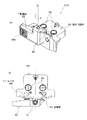
次に、本実施形態の記録装置1の主たる特徴部である切断機構30について図2、図3等を参照して説明する。図2は、図1の矢印A方向から見た、本実施形態の切断装置の構成を示す斜視図であり、図3は、切断装置の側面図である。
Next, the
図2、図3に示すように、切断装置30は、被記録材3をその幅方向に切断するためのカッタユニット40と、該カッタユニット40の下方に設けられた一対の挟持ユニット60とを有している。
As shown in FIGS. 2 and 3, the cutting
特に限定されるものではないが、カッタユニット40及び挟持ユニット60はいずれも、装置本体に固定された支持部材31に取り付けられている。支持部材31は、板金を折り曲げて形成されたものであり、図2に示すように、その上面側にはY方向に延在するレール33が固定されている。また、支持部材31の一部には支持面34が形成されており、この支持面34は被記録材3の搬送方向(鉛直方向)と平行な平坦面となっている。なお、支持面34は、後述するように挟持ユニット60の部材と協働して被記録材3を挟持するための面である。
Although not particularly limited, the
カッタユニット40は、図4にも示すように、レール33に沿ってY方向に往復移動自在に構成されたベース部材46と、それに対して着脱自在に構成されたカッタ刃保持部材41とで構成されている。ベース部材46には、カッタ刃保持部材41側の係合凸部49が挿入される係合凹部48が形成されると共に、部材両側面には、係合溝47が形成されている。
As shown in FIG. 4, the
カッタ刃保持部材41は、被記録材3を挟んで対向配置された一対のロータリ刃42a、42bを備えると共に(図5参照)、これらのロータリ刃の間に被記録材3を導くための導入部45を有している(図4参照)。ロータリ刃42a、42bはそれぞれ、支軸に対して回転自在に取り付けられ、その刃先は被記録材3に直交するようになっている。カッタ刃保持部材41はまた、ベース部材46側の構造部と係合するための係合凸部49及び係合爪42を有している。なお、ロータリ刃に代えて、板状のカット刃を利用することも可能であるが、ロータリ刃は、比較的厚みのある被記録材(例えばターポリン等)を良好に切断することができるという利点がある。
The cutter
このように構成されたカッタ刃保持部材41は、第1の使用態様として、図4(a)に示すような姿勢でベース部材46に対して取り付けられる。このように取り付けられた場合、図2に示すように、カッタユニット40をY方向に沿って、図示奥側から図示手前側にスライドさせることにより被記録材3の切断が行われる。
The cutter
本実施形態のカッタ刃保持部材41は、図4(b)に示すように、挿入方向軸R1回りに180°回転させて、上下反転の状態でもベース部材46に取り付けることができるようになっている(第2の使用態様)。この場合、導入部45は、図4(a)の状態とは逆向きとなり、上記とは反対方向にカッタユニット40をスライドさせることにより被記録材の切断が行われる。
As shown in FIG. 4B, the cutter
なお、本実施形態においては、カッタユニット40のY方向へのスライド(移動)は作業者により手動で行われるものである。但し、カッタユニット40は、被記録材を幅方向に切断するものであれば上記構成に限定されるものではない。例えば、カッタ刃が図示Y方向に自動的に移動して被記録材の切断を行うオートカッタを利用することも可能である。
In this embodiment, the
次に、挟持ユニット60について説明する。本実施形態では、図2に示すように、挟持ユニット60として、被記録材3の幅方向の両端にそれぞれ1つずつ挟持ユニット60A、60Bが配置されている。それぞれの挟持ユニット60A、60Bはいずれも同様の構成を有しているため、以下の説明では、一方の挟持ユニット60Aを例に挙げて説明するものとする。
Next, the clamping
挟持ユニット60Aは、図6に示すように、回転軸R2を中心として回動するように構成された可動部材68と、該可動部材68を装置側の支持部材31(図2参照)に固定するための取付け部材69とを有している。取付け部材69の上面には、2つの係合ローラ65が設けられており、この係合ローラ65が支持部材31の下面側に設けられたレール35に係合するようになっている。このような形態で取付け部材69が支持部材31に取り付けられていることにより、図2の白抜き矢印で示すように、挟持ユニット60A、60Bはいずれも、図示Y方向に移動可能となっている。これは、一対の挟持ユニット60A、60B間の距離が可変となっていることを意味し、このような構成とすることで、幅寸法の異なる複数種の被記録材を用いる場合であっても、その両端部を良好に支持できるものとなる。
As shown in FIG. 6, the clamping
回転軸R2は、特に限定されるものではないが、鉛直方向となるように設定されている。可動部材68と取付け部材69との間には、コイルバネ64が圧縮された状態で配置されており、このコイルバネ64の付勢力により、可動部材68が、図6(a)の矢印方向に回転する向きに付勢された状態となっている。すなわち、この状態では、可動部材68の当接部62が、支持部材31の支持面34に対して所定の付勢力で押し当たるようになっている。したがって、この当接部62と支持面34との間に被記録材3の両端部を挟むことにより、被記録材3が挟持されることとなる。
The rotation axis R 2 is not particularly limited, but is set to be in the vertical direction. A
上記のように構成された記録装置30の使用方法について、以下に説明する。なお、前提として、本実施形態の記録装置1では、記録動作の終了後、被記録材3の切断される位置(切断位置)がロータリ刃42a、42bによって挟まれる位置となるまで、被記録材3が搬送され、その位置で搬送が停止されるようになっている。
A method for using the
このようにして被記録材3の搬送が停止された状態で、作業者はまず、各挟持ユニット60A、60BをY方向に移動させ、可動部材68と支持面34との間で被記録材3の両端部を挟持する。このように被記録材3を切断位置の直下で挟持することにより、垂れ下がった分の被記録材の自重が切断位置に加わらなくなる。
With the conveyance of the
次いで、被記録材3の両端部を挟持したままの状態で、カッタユニット40をY方向に移動させることにより、被記録材3が一方の端部から他方の端部に向かって徐々に切断されることとなる。このように被記録材3を一方向に切断する場合であっても、切断位置の下方において被記録材3が挟持されているため、切断の終盤で垂れ下がった被記録材が傾くことがなくなり、ひいては、切断線が曲がったり、被記録材が破断したりすることが防止される。
Next, the
なお、図4に示した通り、本実施形態に係るカッタユニット40は、カッタ刃保持部材41の向きを180°反転できるように構成されている。したがって、上記切断工程が終了した後、保持部材41を反転させてベース部材46に付け直すことにより、上記工程とは逆向きに被記録材を切断することが可能である。
As shown in FIG. 4, the
本実施形態に係るカッタユニット40は、このように、被記録材をその幅方向に沿って一方向に切断するものであり、また、一回の切断工程で被記録材を切り分けることが可能である。これに対して、特許文献1の構成では、被記録材を切り分けるのに複数の切断工程を要し、そのため工程が煩雑化したり、あるいは、双方向に切断可能なカット刃を用意したりする必要がある。つまり、本発明による利点の1つとしては、一方向にのみ切断可能なカット刃を用いる場合であっても被記録材を良好に切断することができるということが挙げられる。
As described above, the
もっとも、これは、本発明の切断装置が、一方向にのみ切断可能なカット刃を備えたものに限定されることを意図するものではない。双方向に切断可能なカット刃を利用する構成、あるいは、何回かの工程に分けて被記録材を切り分けるような構成であったとしても、本発明による作用効果は上記同様に得られる。 However, this is not intended to limit the cutting device of the present invention to a cutting device that includes a cutting blade that can cut only in one direction. Even if it is configured to use a cutting blade that can be cut in both directions, or configured to cut the recording material in several steps, the effects of the present invention can be obtained in the same manner as described above.
本実施形態では挟持ユニット60A、60BのそれぞれがY方向に移動可能に構成され、ユニット60A、60B間の距離が可変となっていることから、被記録材3の幅寸法が変わった場合であっても良好に対応することが可能である。なお、挟持ユニット60A、60BのY方向への移動は、ユニット60A、60Bがレール35に沿って連続的に移動するものであってもよいし、所定距離移動させるごとにクリック感が得られるような構成となっていてもよい。ここで、上記所定距離は、使用を予定している被記録材の幅寸法に応じて設定されるものであってもよい。
In this embodiment, each of the sandwiching
また、本実施形態のカッタユニット40は、カッタ刃保持部材41がベース部材46に対して着脱自在に構成されているため次のような利点が得られる。すなわち、カッタユニット40を、カッタ刃保持部材41とベース部材46との一体部材として構成した場合、例えばロータリ刃が損傷した際にはユニット全体を交換する必要が生じる。これに対して、本実施形態のようにカッタ刃保持部材41を別体とすれば、カッタ刃保持部材側のみを交換するだけで対応することができる。更に言えば、この種の記録装置においては、厚みや硬度の異なる種々の被記録材3が用いられることもあり、被記録材3の種類に応じてロータリ刃の変更が必要となることもある。こうした観点からしても、カッタ刃保持部材とベース部材とが別体に構成されていることは、交換時の作業性が向上する点で好ましい。
Moreover, since the cutter
本実施形態の切断装置は、上記の他にも、より具体的には下記のような構成を有するものであってもよい。当接部62(図6等参照)は、被記録材3の記録が施された側の面(記録面)に接する構造部である。したがって、この記録面を傷つけたり、あるいは、記録面に挟持跡を付けたりすることがないよう、当接部62の形状を適宜形成することが好ましい。本実施形態に係る当接部62は、一例として、ほぼ半球状の突起部として形成され、被記録材の記録面に点接触するものとして構成されている。但し、これに限定されるものではなく、記録面に対して線接触するような突起部として構成することも可能である。記録装置の構成などによっても異なるが、例えば、切断を行う時点で未だ記録面のインクが完全に乾燥していないような構成の場合、上記のように点接触または線接触するような当接部62とすることは、次の点で有利である。すなわち、記録面のインクが完全に乾燥していないような場合、面接触の形態で当接部62が記録面に接触すると、記録面の画像品質を低下させてしまう場合がある。したがって、こうした場合には、点接触または線接触といったように接触面積をなるべく小さくすることで、画像品質の低下を防止することが可能となるためである。
In addition to the above, the cutting device of the present embodiment may more specifically have the following configuration. The abutting portion 62 (see FIG. 6 and the like) is a structural portion that is in contact with the surface (recording surface) on which the
一方、被記録材の材質によっては(あるいは、当接部62の記録面に対する接触圧によっては)、上記のように点接触させるようにすると、逆に記録面に挟持跡を付けてしまう原因となる。したがって、上記のように点接触または線接触させるようにするか、あるいは、面接触させるようにするかは、記録装置の構成や被記録材の材質等に応じて選び分けることが好ましい。
On the other hand, depending on the material of the recording material (or depending on the contact pressure of the
本発明は、上述したように、被記録材の切断位置の下方において被記録材を挟持した状態で切断を行うようにしたことで、切分けられる側の被記録材が自重により傾くことがなくなり、切断不良が防止されるという作用効果を奏するものである。つまり、切断位置の下方において被記録材を挟持(保持)することができるのであれば、挟持ユニット60A、60Bの構成を変更したとしても、本発明による作用効果は同様にして得られることとなる。例えば、被記録材の中央部を保持するような保持機構を利用してもよいし、または、被記録材を全幅にわたって保持するような保持機構を利用してもよい。
In the present invention, as described above, since the recording material is cut in a state where the recording material is sandwiched below the cutting position of the recording material, the recording material on the side to be separated is not inclined by its own weight. There is an effect that cutting failure is prevented. That is, if the recording material can be held (held) below the cutting position, the effects of the present invention can be obtained in the same manner even if the configuration of the holding
上記実施形態では、図1に示すように、カッタユニット40は下流側ガイド部材19の下方に配置され、鉛直方向に垂れ下がった部位において被記録材3を切断するものであったが、これに限定されるものではない。例えば、被記録材が下流側ガイド部材19のガイド面で切断されるような構成であったとしても、そこから垂れ下がった分の被記録材の自重が切断位置に加わることには変わりがない。したがって、そのような構成であったとしても、切断位置より下方に、例えば上記挟持ユニット60A、60Bを設け、切断時に被記録材を保持するようにすることが好ましい。
In the above embodiment, as shown in FIG. 1, the
1 記録装置
3 被記録材
5 記録部
7 記録ヘッド
11 供給ロール
19 下流側ガイド部材
30 切断装置
34 支持面
40 カッタユニット
42a、42b ロータリ刃
45 導入部
60、60A、60B 挟持ユニット
62 当接部
64 コイルバネ
68 可動部材
DESCRIPTION OF SYMBOLS 1
Claims (9)
前記保持機構は前記ガイド部材より前記搬送方向の下流に配置され、
前記カッタユニットは前記ガイド部材と前記保持機構の間に配置され、
前記保持機構は、前記ガイド部材から鉛直方向に垂下がった前記被記録材の両端部を保持し、
前記カッタユニットで前記被記録材を切断する場合は、前記保持機構によって前記ガイド部材から垂下がった前記被記録材の両端部を保持したまま前記カッタユニットによって前記被記録材の前記ガイド部材から垂下がった部分を切断し、該切断完了時は前記保持機構によって前記被記録材を落下させずに保持することを特徴とする切断装置。 A cutter unit that cuts a long sheet-like recording material in its width direction, a recording unit that discharges ink to the recording material, and a recording unit that is arranged downstream of the recording unit in the conveying direction of the recording material A guide member for guiding the recording material to be recorded, and a holding mechanism provided at a position below the cutter unit,
The holding mechanism is disposed downstream of the guide member in the transport direction,
The cutter unit is disposed between the guide member and the holding mechanism;
The holding mechanism holds both ends of the recording material hanging vertically from the guide member,
When the recording material is cut by the cutter unit, the recording unit is suspended from the guide member of the recording material by the cutter unit while holding both ends of the recording material suspended from the guide member by the holding mechanism. down portion was cut during the cutting is completed the cutting device, characterized in that the holding without dropping the recording material by the holding mechanism.
前記保持機構によって、前記ガイド部材から鉛直方向に垂下がった前記被記録材の両端部を保持する工程と、
前記保持機構によって前記ガイド部材から垂下がった前記被記録材の両端部を保持したまま前記カッタユニットによって前記被記録材の前記ガイド部材から垂下がった部分を切断する工程と、を有し、
該切断する工程完了時において前記保持機構によって前記被記録材を落下させずに保持することを特徴とする切断方法。 A cutter unit that cuts a long sheet-like recording material in its width direction, a recording unit that discharges ink to the recording material, and a recording unit that is arranged downstream of the recording unit in the conveying direction of the recording material A guide member for guiding the recording material to be recorded, and a holding mechanism provided at a position below the cutter unit, the holding mechanism being disposed downstream of the guide member in the transport direction, The cutter unit is a cutting method of a cutting device disposed between the guide member and the holding mechanism,
A step of holding both ends of the recording material hanging vertically from the guide member by the holding mechanism;
Cutting the portion of the recording material suspended from the guide member by the cutter unit while holding both ends of the recording material suspended from the guide member by the holding mechanism, and
A cutting method comprising: holding the recording material without dropping by the holding mechanism when the cutting step is completed .
Priority Applications (2)
| Application Number | Priority Date | Filing Date | Title |
|---|---|---|---|
| JP2005248135A JP4523521B2 (en) | 2005-08-29 | 2005-08-29 | Cutting device, recording device equipped with the cutting device, and sheet-like member cutting method |
| PCT/JP2006/313843 WO2007026469A1 (en) | 2005-08-29 | 2006-07-12 | Cutter, recorder having the cutter, and method of cutting sheet-like member |
Applications Claiming Priority (1)
| Application Number | Priority Date | Filing Date | Title |
|---|---|---|---|
| JP2005248135A JP4523521B2 (en) | 2005-08-29 | 2005-08-29 | Cutting device, recording device equipped with the cutting device, and sheet-like member cutting method |
Publications (3)
| Publication Number | Publication Date |
|---|---|
| JP2007062045A JP2007062045A (en) | 2007-03-15 |
| JP2007062045A5 JP2007062045A5 (en) | 2008-09-18 |
| JP4523521B2 true JP4523521B2 (en) | 2010-08-11 |
Family
ID=37808572
Family Applications (1)
| Application Number | Title | Priority Date | Filing Date |
|---|---|---|---|
| JP2005248135A Active JP4523521B2 (en) | 2005-08-29 | 2005-08-29 | Cutting device, recording device equipped with the cutting device, and sheet-like member cutting method |
Country Status (2)
| Country | Link |
|---|---|
| JP (1) | JP4523521B2 (en) |
| WO (1) | WO2007026469A1 (en) |
Families Citing this family (3)
| Publication number | Priority date | Publication date | Assignee | Title |
|---|---|---|---|---|
| JP5504631B2 (en) * | 2009-01-07 | 2014-05-28 | 三星ダイヤモンド工業株式会社 | Cutter device and cutter holder |
| JP5556475B2 (en) | 2010-07-27 | 2014-07-23 | セイコーエプソン株式会社 | Target conveying apparatus and recording apparatus |
| JP7147547B2 (en) * | 2018-12-25 | 2022-10-05 | 株式会社リコー | Recording medium cutting device, liquid ejection device |
Citations (6)
| Publication number | Priority date | Publication date | Assignee | Title |
|---|---|---|---|---|
| JPH1178140A (en) * | 1997-09-03 | 1999-03-23 | Fuji Photo Film Co Ltd | Cutter for printer |
| JP2978912B1 (en) * | 1998-09-28 | 1999-11-15 | 静岡日本電気株式会社 | Vertical stack mechanism |
| JPH11320992A (en) * | 1998-05-14 | 1999-11-24 | Matsushita Electric Ind Co Ltd | Recording paper cutting device |
| JP2004114211A (en) * | 2002-09-25 | 2004-04-15 | Seiko Epson Corp | Tape processor |
| JP2005014476A (en) * | 2003-06-27 | 2005-01-20 | Oki Data Corp | Medium processor |
| JP2005014095A (en) * | 2003-06-23 | 2005-01-20 | Seiko Epson Corp | Medium cutting device and recording device |
-
2005
- 2005-08-29 JP JP2005248135A patent/JP4523521B2/en active Active
-
2006
- 2006-07-12 WO PCT/JP2006/313843 patent/WO2007026469A1/en active Application Filing
Patent Citations (6)
| Publication number | Priority date | Publication date | Assignee | Title |
|---|---|---|---|---|
| JPH1178140A (en) * | 1997-09-03 | 1999-03-23 | Fuji Photo Film Co Ltd | Cutter for printer |
| JPH11320992A (en) * | 1998-05-14 | 1999-11-24 | Matsushita Electric Ind Co Ltd | Recording paper cutting device |
| JP2978912B1 (en) * | 1998-09-28 | 1999-11-15 | 静岡日本電気株式会社 | Vertical stack mechanism |
| JP2004114211A (en) * | 2002-09-25 | 2004-04-15 | Seiko Epson Corp | Tape processor |
| JP2005014095A (en) * | 2003-06-23 | 2005-01-20 | Seiko Epson Corp | Medium cutting device and recording device |
| JP2005014476A (en) * | 2003-06-27 | 2005-01-20 | Oki Data Corp | Medium processor |
Also Published As
| Publication number | Publication date |
|---|---|
| WO2007026469A1 (en) | 2007-03-08 |
| JP2007062045A (en) | 2007-03-15 |
Similar Documents
| Publication | Publication Date | Title |
|---|---|---|
| JP2013233792A (en) | Image forming apparatus | |
| JP4523521B2 (en) | Cutting device, recording device equipped with the cutting device, and sheet-like member cutting method | |
| JP4507825B2 (en) | Inkjet printer | |
| JP5578867B2 (en) | Cutting device and recording device | |
| JP6163805B2 (en) | Image forming apparatus | |
| JP2010052268A (en) | Recording device | |
| JP7052446B2 (en) | Cutting device and image forming device | |
| JP4457847B2 (en) | Inkjet printer | |
| JP4449743B2 (en) | Printer | |
| JP6347304B2 (en) | Device for conveying sheets | |
| JP2006327080A (en) | Cutter | |
| JP4333575B2 (en) | Printer | |
| JP4400446B2 (en) | Printer | |
| JP4604688B2 (en) | Inkjet printer | |
| JP4277797B2 (en) | Inkjet printer | |
| JP4415823B2 (en) | Inkjet printer | |
| JP4353069B2 (en) | Inkjet printer | |
| JP4333570B2 (en) | Printer | |
| JP4380501B2 (en) | Inkjet printer | |
| JP4457855B2 (en) | Inkjet printer | |
| JP4333571B2 (en) | Printer | |
| JP4259455B2 (en) | Inkjet printer | |
| JP4802496B2 (en) | Inkjet printer | |
| JP2013193217A (en) | Sheet conveyance device and image forming device | |
| JP2006188323A (en) | Ink jet printer |
Legal Events
| Date | Code | Title | Description |
|---|---|---|---|
| A521 | Request for written amendment filed |
Free format text: JAPANESE INTERMEDIATE CODE: A523 Effective date: 20080805 |
|
| A621 | Written request for application examination |
Free format text: JAPANESE INTERMEDIATE CODE: A621 Effective date: 20080805 |
|
| RD01 | Notification of change of attorney |
Free format text: JAPANESE INTERMEDIATE CODE: A7421 Effective date: 20091105 |
|
| RD01 | Notification of change of attorney |
Free format text: JAPANESE INTERMEDIATE CODE: A7421 Effective date: 20091113 |
|
| RD01 | Notification of change of attorney |
Free format text: JAPANESE INTERMEDIATE CODE: A7421 Effective date: 20091118 |
|
| A131 | Notification of reasons for refusal |
Free format text: JAPANESE INTERMEDIATE CODE: A131 Effective date: 20091215 |
|
| A521 | Request for written amendment filed |
Free format text: JAPANESE INTERMEDIATE CODE: A523 Effective date: 20100209 |
|
| A131 | Notification of reasons for refusal |
Free format text: JAPANESE INTERMEDIATE CODE: A131 Effective date: 20100309 |
|
| A521 | Request for written amendment filed |
Free format text: JAPANESE INTERMEDIATE CODE: A523 Effective date: 20100430 |
|
| TRDD | Decision of grant or rejection written | ||
| A01 | Written decision to grant a patent or to grant a registration (utility model) |
Free format text: JAPANESE INTERMEDIATE CODE: A01 Effective date: 20100525 |
|
| A01 | Written decision to grant a patent or to grant a registration (utility model) |
Free format text: JAPANESE INTERMEDIATE CODE: A01 |
|
| A61 | First payment of annual fees (during grant procedure) |
Free format text: JAPANESE INTERMEDIATE CODE: A61 Effective date: 20100527 |
|
| R150 | Certificate of patent or registration of utility model |
Ref document number: 4523521 Country of ref document: JP Free format text: JAPANESE INTERMEDIATE CODE: R150 Free format text: JAPANESE INTERMEDIATE CODE: R150 |
|
| FPAY | Renewal fee payment (event date is renewal date of database) |
Free format text: PAYMENT UNTIL: 20130604 Year of fee payment: 3 |
|
| FPAY | Renewal fee payment (event date is renewal date of database) |
Free format text: PAYMENT UNTIL: 20130604 Year of fee payment: 3 |
|
| R250 | Receipt of annual fees |
Free format text: JAPANESE INTERMEDIATE CODE: R250 |
|
| RD04 | Notification of resignation of power of attorney |
Free format text: JAPANESE INTERMEDIATE CODE: R3D04 |
|
| R250 | Receipt of annual fees |
Free format text: JAPANESE INTERMEDIATE CODE: R250 |
|
| R250 | Receipt of annual fees |
Free format text: JAPANESE INTERMEDIATE CODE: R250 |
|
| R250 | Receipt of annual fees |
Free format text: JAPANESE INTERMEDIATE CODE: R250 |
|
| S111 | Request for change of ownership or part of ownership |
Free format text: JAPANESE INTERMEDIATE CODE: R313111 |
|
| R350 | Written notification of registration of transfer |
Free format text: JAPANESE INTERMEDIATE CODE: R350 |
|
| S111 | Request for change of ownership or part of ownership |
Free format text: JAPANESE INTERMEDIATE CODE: R313111 |
|
| R350 | Written notification of registration of transfer |
Free format text: JAPANESE INTERMEDIATE CODE: R350 |