JP4521000B2 - Air bag and belt tensioner with metal fixing material duct and the use of such a duct and ignition device - Google Patents
Air bag and belt tensioner with metal fixing material duct and the use of such a duct and ignition device Download PDFInfo
- Publication number
- JP4521000B2 JP4521000B2 JP2007008769A JP2007008769A JP4521000B2 JP 4521000 B2 JP4521000 B2 JP 4521000B2 JP 2007008769 A JP2007008769 A JP 2007008769A JP 2007008769 A JP2007008769 A JP 2007008769A JP 4521000 B2 JP4521000 B2 JP 4521000B2
- Authority
- JP
- Japan
- Prior art keywords
- fixing material
- metal
- metal fixing
- material duct
- connection path
- Prior art date
- Legal status (The legal status is an assumption and is not a legal conclusion. Google has not performed a legal analysis and makes no representation as to the accuracy of the status listed.)
- Active
Links
- 229910052751 metal Inorganic materials 0.000 title claims abstract description 204
- 239000002184 metal Substances 0.000 title claims abstract description 204
- 239000000463 material Substances 0.000 title claims abstract description 154
- 239000000758 substrate Substances 0.000 claims description 74
- 230000036961 partial effect Effects 0.000 claims description 58
- 239000011521 glass Substances 0.000 claims description 55
- 230000000903 blocking effect Effects 0.000 claims description 20
- 238000004080 punching Methods 0.000 claims description 17
- 229910000831 Steel Inorganic materials 0.000 claims description 16
- 239000010959 steel Substances 0.000 claims description 16
- 230000009467 reduction Effects 0.000 claims description 8
- 239000000156 glass melt Substances 0.000 claims description 4
- 238000005549 size reduction Methods 0.000 claims description 3
- 239000000919 ceramic Substances 0.000 claims description 2
- 239000002241 glass-ceramic Substances 0.000 claims description 2
- 229920000642 polymer Polymers 0.000 claims description 2
- 229910000975 Carbon steel Inorganic materials 0.000 claims 1
- 238000000034 method Methods 0.000 description 18
- 238000004519 manufacturing process Methods 0.000 description 13
- 230000008569 process Effects 0.000 description 13
- 238000004873 anchoring Methods 0.000 description 7
- 230000015572 biosynthetic process Effects 0.000 description 7
- 238000005498 polishing Methods 0.000 description 7
- 239000002360 explosive Substances 0.000 description 6
- 230000006870 function Effects 0.000 description 6
- 230000008901 benefit Effects 0.000 description 5
- 239000004020 conductor Substances 0.000 description 5
- 238000002844 melting Methods 0.000 description 5
- 230000008018 melting Effects 0.000 description 5
- 238000000465 moulding Methods 0.000 description 5
- 229910000851 Alloy steel Inorganic materials 0.000 description 4
- XEEYBQQBJWHFJM-UHFFFAOYSA-N Iron Chemical compound [Fe] XEEYBQQBJWHFJM-UHFFFAOYSA-N 0.000 description 4
- 230000008859 change Effects 0.000 description 4
- 238000001816 cooling Methods 0.000 description 4
- 238000010438 heat treatment Methods 0.000 description 4
- 230000002706 hydrostatic effect Effects 0.000 description 4
- 230000002829 reductive effect Effects 0.000 description 4
- 229910001315 Tool steel Inorganic materials 0.000 description 3
- 229910045601 alloy Inorganic materials 0.000 description 3
- 239000000956 alloy Substances 0.000 description 3
- 238000001125 extrusion Methods 0.000 description 3
- 239000000843 powder Substances 0.000 description 3
- 239000011347 resin Substances 0.000 description 3
- 229920005989 resin Polymers 0.000 description 3
- 238000000926 separation method Methods 0.000 description 3
- OAICVXFJPJFONN-UHFFFAOYSA-N Phosphorus Chemical compound [P] OAICVXFJPJFONN-UHFFFAOYSA-N 0.000 description 2
- 101100005555 Rattus norvegicus Ccl20 gene Proteins 0.000 description 2
- PXIPVTKHYLBLMZ-UHFFFAOYSA-N Sodium azide Chemical compound [Na+].[N-]=[N+]=[N-] PXIPVTKHYLBLMZ-UHFFFAOYSA-N 0.000 description 2
- NINIDFKCEFEMDL-UHFFFAOYSA-N Sulfur Chemical compound [S] NINIDFKCEFEMDL-UHFFFAOYSA-N 0.000 description 2
- 230000009471 action Effects 0.000 description 2
- 229910052782 aluminium Inorganic materials 0.000 description 2
- XAGFODPZIPBFFR-UHFFFAOYSA-N aluminium Chemical compound [Al] XAGFODPZIPBFFR-UHFFFAOYSA-N 0.000 description 2
- 238000000137 annealing Methods 0.000 description 2
- 239000011248 coating agent Substances 0.000 description 2
- 238000000576 coating method Methods 0.000 description 2
- 230000006835 compression Effects 0.000 description 2
- 238000007906 compression Methods 0.000 description 2
- 230000007797 corrosion Effects 0.000 description 2
- 238000005260 corrosion Methods 0.000 description 2
- 230000008878 coupling Effects 0.000 description 2
- 238000010168 coupling process Methods 0.000 description 2
- 238000005859 coupling reaction Methods 0.000 description 2
- 238000005520 cutting process Methods 0.000 description 2
- 238000011161 development Methods 0.000 description 2
- 238000010586 diagram Methods 0.000 description 2
- -1 for example Substances 0.000 description 2
- 229910052742 iron Inorganic materials 0.000 description 2
- 239000000155 melt Substances 0.000 description 2
- 239000011574 phosphorus Substances 0.000 description 2
- 229910052698 phosphorus Inorganic materials 0.000 description 2
- 238000007517 polishing process Methods 0.000 description 2
- 229920001296 polysiloxane Polymers 0.000 description 2
- 230000002265 prevention Effects 0.000 description 2
- 239000003380 propellant Substances 0.000 description 2
- 230000002441 reversible effect Effects 0.000 description 2
- 238000004904 shortening Methods 0.000 description 2
- 229910001220 stainless steel Inorganic materials 0.000 description 2
- 239000010935 stainless steel Substances 0.000 description 2
- 239000011593 sulfur Substances 0.000 description 2
- 229910052717 sulfur Inorganic materials 0.000 description 2
- 230000007704 transition Effects 0.000 description 2
- 238000003466 welding Methods 0.000 description 2
- 239000006096 absorbing agent Substances 0.000 description 1
- 230000002411 adverse Effects 0.000 description 1
- 238000007596 consolidation process Methods 0.000 description 1
- 230000001419 dependent effect Effects 0.000 description 1
- 230000006866 deterioration Effects 0.000 description 1
- 238000009826 distribution Methods 0.000 description 1
- 230000000694 effects Effects 0.000 description 1
- 238000005868 electrolysis reaction Methods 0.000 description 1
- 238000005516 engineering process Methods 0.000 description 1
- 239000012530 fluid Substances 0.000 description 1
- PCHJSUWPFVWCPO-UHFFFAOYSA-N gold Chemical compound [Au] PCHJSUWPFVWCPO-UHFFFAOYSA-N 0.000 description 1
- 239000010931 gold Substances 0.000 description 1
- 229910052737 gold Inorganic materials 0.000 description 1
- 239000003721 gunpowder Substances 0.000 description 1
- 238000003780 insertion Methods 0.000 description 1
- 230000037431 insertion Effects 0.000 description 1
- 239000011810 insulating material Substances 0.000 description 1
- 239000012212 insulator Substances 0.000 description 1
- 230000010354 integration Effects 0.000 description 1
- 238000005259 measurement Methods 0.000 description 1
- 230000007246 mechanism Effects 0.000 description 1
- 150000002739 metals Chemical class 0.000 description 1
- 238000012986 modification Methods 0.000 description 1
- 230000004048 modification Effects 0.000 description 1
- 229920002959 polymer blend Polymers 0.000 description 1
- 239000011591 potassium Substances 0.000 description 1
- 229910052700 potassium Inorganic materials 0.000 description 1
- 238000012545 processing Methods 0.000 description 1
- 230000001681 protective effect Effects 0.000 description 1
- 239000002994 raw material Substances 0.000 description 1
- 239000004576 sand Substances 0.000 description 1
- 230000035939 shock Effects 0.000 description 1
- 238000004513 sizing Methods 0.000 description 1
- 238000009751 slip forming Methods 0.000 description 1
- 238000012360 testing method Methods 0.000 description 1
- XLYOFNOQVPJJNP-UHFFFAOYSA-N water Substances O XLYOFNOQVPJJNP-UHFFFAOYSA-N 0.000 description 1
Images


Classifications
-
- F—MECHANICAL ENGINEERING; LIGHTING; HEATING; WEAPONS; BLASTING
- F42—AMMUNITION; BLASTING
- F42B—EXPLOSIVE CHARGES, e.g. FOR BLASTING, FIREWORKS, AMMUNITION
- F42B3/00—Blasting cartridges, i.e. case and explosive
- F42B3/10—Initiators therefor
- F42B3/195—Manufacture
- F42B3/198—Manufacture of electric initiator heads e.g., testing, machines
-
- F—MECHANICAL ENGINEERING; LIGHTING; HEATING; WEAPONS; BLASTING
- F42—AMMUNITION; BLASTING
- F42B—EXPLOSIVE CHARGES, e.g. FOR BLASTING, FIREWORKS, AMMUNITION
- F42B3/00—Blasting cartridges, i.e. case and explosive
- F42B3/10—Initiators therefor
- F42B3/103—Mounting initiator heads in initiators; Sealing-plugs
Landscapes
- Engineering & Computer Science (AREA)
- General Engineering & Computer Science (AREA)
- Manufacturing & Machinery (AREA)
- Air Bags (AREA)
- Emergency Lowering Means (AREA)
- Adhesives Or Adhesive Processes (AREA)
- Insertion Pins And Rivets (AREA)
- Joining Of Glass To Other Materials (AREA)
- Lighters Containing Fuel (AREA)
- Gasket Seals (AREA)
- Feeding, Discharge, Calcimining, Fusing, And Gas-Generation Devices (AREA)
- Automotive Seat Belt Assembly (AREA)
Abstract
Description
本発明は、詳しくは、エアバッグまたはベルトテンショナの点火器に用いる金属固定材料ダクトに関する。さらに、その使用ならびに金属固定材料ダクトを含む点火装置を備えるガス発生器、エアバッグおよびベルトテンショナに関する。 More particularly, the present invention relates to a metal fixing material duct used for an igniter of an air bag or a belt tensioner. It further relates to its use and gas generator, airbag and belt tensioner comprising an ignition device including a metal fixing material duct.
金属固定材料ダクトは、種々の実施形態で従来の技術から公知である。それらの中には、固定材料、特に金属内のガラスまたは樹脂の真空気密の溶融も含まれている。その際に前記金属は、導電体として機能する。ここで代表として特許文献1、特許文献2を参照されたい。この種のダクトは、電子技術および電気技術で広く普及している。ここで溶融のために使用される材料、特にガラスは、絶縁体として用いられる。典型的な金属固定材料ダクトは、金属製の内部導体が予成形された焼結ガラス部品の中に溶融されるように構成されており、前記焼結ガラス部品またはガラス管が、いわゆる基体を有する外部金属部品の中に溶融される。この種の金属固定材料ダクトの好ましい適用として、例えば点火装置がある。このような点火装置は、特に自動車におけるエアバッグまたはベルトテンショナに使用される。この場合、金属固定材料ダクトが点火装置の構成要素である。全点火装置は、金属固定材料ダクトのほかに、点火ブリッジ、爆薬ならびに点火機構を気密に取り囲む金属カバーを含む。ダクトを通して1本または2本あるいは2本以上の金属ピンを貫通させることができる。
Metal fixing material ducts are known from the prior art in various embodiments. Among them are the vacuum-tight melting of fixing materials, especially glass or resin in metals. At that time, the metal functions as a conductor. Here, refer to
金属ピンを用いる好ましい実施形態において、ハウジングは、アース上にあり、好ましい2極の実施形態においては、前記ピンの1つがアース上にある。前記点火器もしくは点火装置は、特に自動車におけるエアバッグまたはベルトテンショナに使用される。前記または類似の形式の公知の点火器は、特許文献3、特許文献4、特許文献5、特許文献6、特許文献7、特許文献8、特許文献9、特許文献10、特許文献11、特許文献12、特許文献13、特許文献14ならびに特許文献15および特許文献16に記載されており、それらの開示内容は全面的に本願に併せて採用する。前記点火ユニットは、2本の金属ピンを有する。しかしまた、1本のピンのみを有する電子点火器も可能である。
In a preferred embodiment using metal pins, the housing is on ground, and in a preferred bipolar embodiment, one of the pins is on ground. The igniter or igniter is used particularly for an airbag or a belt tensioner in an automobile. Known or similar types of igniters are disclosed in
従来の技術に示されている点火器は、金属基体、例えば回動部として形成された金属スリーブまたは樹脂製の基体を含む。前記金属基体は、少なくとも1つの連結路開口部を有し、前記開口部を通して少なくとも1本の金属ピンが通される。ここで前記実施形態の本質的な問題は、この種の実施形態が材料およびコストを非常に多く必要とし、さらに回動部としての実施形態によって円形の断面と異なる連結路開口部の実施形態が追加費用をかけてのみ可能であることにある。さらに、前記回動部は、比較的大きい寸法を特徴とし、これは相応に要求される全点火器の寸法決定に現れる。 The igniter shown in the prior art includes a metal base, for example, a metal sleeve formed as a rotating part or a resin base. The metal substrate has at least one connection path opening, and at least one metal pin is passed through the opening. Here, the essential problem of the above embodiment is that this type of embodiment requires a great deal of material and cost, and further, the embodiment of the connecting path opening is different from the circular cross section depending on the embodiment as a rotating part. It is possible only at an additional cost. Furthermore, the pivoting part is characterized by a relatively large size, which appears in the correspondingly required sizing of all igniters.
特許文献15から、絶縁材料内に配置された一組の電極と、ハウジングの形態の基体とを含む点火ユニットの実施形態が公知である。点火の解除時に発生する圧力に対する抵抗力の増大と共に押出力を増大する手段が相互に作用結合する金属固定材料ダクトの構成部品に設けられている。このような手段は、固定材料、電極または基体に隣接する要素に形成される平面に構成されている。ここで基体の実施形態は、少なくとも1つの段、すなわちダクト開口内の断面変化を含み、これらの手段は、点火過程中に圧力にさらされる平面で表面積の拡大を生ぜしめる。基体用の材料選択に関しては全く制限がないため、その結果、この場合それぞれの実施形態に応じて、特に回動部としての形成時に同様に付加的に要求される引締力もしくは押出力を増大する相応の手段の挿入によってさらに厳しくなる前記欠点が発生する。 From US Pat. No. 6,099,056, an embodiment of an ignition unit is known that includes a set of electrodes arranged in an insulating material and a base in the form of a housing. Means for increasing the pushing force with increasing resistance to the pressure generated when the ignition is released are provided in the components of the metal anchoring material duct that are operatively coupled to each other. Such means are constructed in the plane formed in the element adjacent to the fixing material, electrode or substrate. Embodiments of the substrate here include at least one step, i.e. a cross-sectional change in the duct opening, which causes an increase in surface area in a plane that is exposed to pressure during the ignition process. Since there is no restriction on the selection of the material for the substrate, as a result, in this case, depending on the respective embodiments, particularly the tightening force or the pushing force required in addition as well when forming as a rotating part is increased. The above disadvantages become more severe by the insertion of corresponding means.
一般的な金属固定材料ダクトは、特許文献16の刊行物から公知である。この刊行物は、特殊な形成において少なくとも1本の金属ピンが通されている金属基体を備えるガラス金属ダクトと呼ばれる金属固定材料ダクトを開示する。好ましい一実施形態において2本の金属ピンを設けたとき、両方のピンの一方が少なくとも間接的に、すなわち直接的または間接的に別の要素を介して基体とのアース接続を構築する。 A typical metal fixing material duct is known from the publication of WO-A-03 / 09797. This publication discloses a metal fixing material duct, called a glass metal duct, comprising a metal substrate through which at least one metal pin is threaded in a special formation. When two metal pins are provided in a preferred embodiment, one of both pins establishes a ground connection with the substrate at least indirectly, ie directly or indirectly through another element.
2本の金属ピンを備える実施形態において、前記金属ピンは、好ましくは互いに平行に配置されている。その際前記金属ピンの少なくとも一方が基体内の連結路開口部の中に配置され、この基体に対して、好ましくはガラス栓の形態の固定材料によって固定される。前記基体は、薄板部材から形成され、第1の実施形態において少なくとも連結路開口部が分離工程、特にスタンピングによって製造される。基体自体は、好ましくは同様に全材料から打ち抜かれるが、基体の最終形状は成形プロセス、例えば深絞りによって得られる。好ましい一実施形態において、すでに外部輪郭を表す最終形状と、連結路開口部を表す基本形状も、少なくとも分離工程、特にスタンピングによって製造される。最終形状とは、この最終形状でそれ以上成形工程を行う必要のないことを意味する。基本形状とは、全く必要のないその他の変更時の最終形状を表すかまたはこの最終形状で別の製造方法、特に成形方法による変更をまだ実施できることを意味し、前記最終形状は、前記の付加的な方法によって初めて得られる。 In an embodiment comprising two metal pins, the metal pins are preferably arranged parallel to each other. In this case, at least one of the metal pins is arranged in a connection channel opening in the substrate and is fixed to the substrate by a fixing material, preferably in the form of a glass plug. The base is formed of a thin plate member, and in the first embodiment, at least the connection path opening is manufactured by a separation process, particularly stamping. The substrate itself is preferably stamped out of all materials as well, but the final shape of the substrate is obtained by a molding process, for example deep drawing. In a preferred embodiment, the final shape already representing the outer contour and the basic shape representing the connecting channel opening are also produced at least by a separation process, in particular stamping. The final shape means that it is not necessary to perform any further molding steps with this final shape. The basic shape represents the final shape at the time of other changes that are not required at all, or means that this final shape can still be modified by another manufacturing method, in particular a molding method, Can be obtained for the first time by a traditional method.
正面と裏面との間に、特に点火時に、連結路開口部の内周に対する裏面の方向への固定材料の相対運動を回避する手段を設けている。前記手段は、基体の集積構成部品であり、またはこの基体と共に1つの構造上のユニットを形成する。スタンピングによる基体の製造は、長所として製造時間の短縮を提供し、特に連結路開口部の自由な形成を可能にする。もちろん、このスタンピングによる製造は、材料に依存する個別パラメータに関して限度が設けられており、その限度の超過は製造を非経済的にさせ、さらに調製できる押出力に不利に影響する。
従って、本発明の基礎におく課題は、スタンピングによって得られる少なくとも1つの連結路開口部を有し、かつ少ない材料および少ない作業費用で高い強度と同時に大きい押出力を特徴とする基体を備える、冒頭に述べた形式の金属固定材料ダクトを提供することである。さらに、個々の要素の不正確な組込みによって生じる組立ミスが回避されるべきである。 The problem underlying the present invention is therefore to provide a base which has at least one connection channel opening obtained by stamping and which is characterized by high material strength and at the same time high strength with low material and low operating costs. It is to provide a metal fixing material duct of the type described in. Furthermore, assembly errors caused by improper integration of the individual elements should be avoided.
本発明による解決策は、請求項1の特徴によって特徴づけられる。好ましい実施形態は、従属請求項に記載されている。
The solution according to the invention is characterized by the features of
本発明に係る金属固定材料ダクトは、固定材料内の基体内の連結路開口部の中に配置された少なくとも1本の金属ピンを含み、前記基体は正面および裏面を有する。前記基体の正面と裏面との間に、連結路開口部の内周に対する裏面の方向への固定材料の相対運動を阻止(回避)する阻止手段を設けている。 The metal anchoring material duct according to the present invention includes at least one metal pin disposed in a connection path opening in a substrate within the anchoring material, the substrate having a front surface and a back surface. Between the front surface and the back surface of the base, there is provided a blocking means for blocking (avoiding) relative movement of the fixing material in the direction of the back surface with respect to the inner periphery of the connection path opening.
一般的に、金属固定材料ダクトは、いわゆる押出力および引出力によって特徴づけることができる。前記押出力は、金属固定材料ダクトの連結路開口部の中に取り込まれる固定材料をダクトから押し出すために適用する必要がある、そのような力である。押出力の大きさは、静水力学的または機械的のいずれかで決定できる。 In general, metal fixing material ducts can be characterized by so-called pushing and pulling forces. Said pushing force is such a force that needs to be applied in order to push out the fixing material taken into the connection opening of the metal fixing material duct from the duct. The magnitude of the pushing force can be determined either hydrostatically or mechanically.
押出力が機械的に決定されるとき、固定材料の平面がスタンプによって打ちつけられ、固定材料に押圧するスタンプの面積は、固定材料の面積よりも小さい。 When the pushing force is mechanically determined, the plane of the fixing material is struck by the stamp, and the area of the stamp that presses against the fixing material is smaller than the area of the fixing material.
その別法として、前記押出力は、静水力学的に測定することができる。静水力学的測定の場合は、固定材料が静水圧例えば水圧で付勢され、どの程度の静水圧で固定材料が連結路開口部から押出されるかが測定される。 As an alternative, the pushing force can be measured hydrostatically. In the case of hydrostatic measurement, the fixing material is energized by hydrostatic pressure, for example, water pressure, and the degree of hydrostatic pressure at which the fixing material is pushed out from the connection path opening is measured.
引出力は、金属固定材料ダクトの金属ピンを固定材料から引き出すために必要な力として生じる。 The pulling force is generated as a force required to pull the metal pin of the metal fixing material duct from the fixing material.
基体には、少なくともその連結路開口部がスタンピングで製造されている。本発明の継続形成された一実施形態において、全基体すなわち基体の外周ならびに連結路開口部をスタンピングで製造することもできる。その場合、基体は、打抜き部として形成される。 The base body is manufactured by stamping at least the connection path opening. In a continuously formed embodiment of the present invention, the entire substrate, i.e. the outer periphery of the substrate, as well as the connecting channel opening can be manufactured by stamping. In that case, the substrate is formed as a punched portion.
本発明により、基体は、基体の厚さと連結路開口部の最大拡径部との間の比が連結路開口部の軸方向と垂直に0.5を含む2.5までの間の範囲になるように形成されている。連結路開口部の打抜き後、ただし連結路開口部の研磨前の連結路開口部の最大拡径部に対する基体の厚さDの比を考察すると、この比は、好ましくは0.6から2.5の範囲にある。連結路開口部の最大拡径部に対する基体の厚さDの比を連結路開口部の研磨工程後に考察すると、この比は、好ましくは0.5から2の範囲にある。 According to the present invention, the base body has a ratio between the thickness of the base body and the maximum diameter-expanded portion of the connection path opening in a range of up to 2.5 including 0.5 perpendicular to the axial direction of the connection path opening. It is formed to become. Considering the ratio of the substrate thickness D to the maximum diameter expanded portion of the connection path opening after punching the connection path opening but before polishing of the connection path opening, this ratio is preferably 0.6 to 2. It is in the range of 5. When considering the ratio of the substrate thickness D to the maximum diameter expansion portion of the connection path opening after the polishing process of the connection path opening, this ratio is preferably in the range of 0.5 to 2.
特に好ましい一実施形態に従って、基体の厚さDと連結路開口部の最大拡径部との間の比は、連結路開口部の軸方向と垂直に研磨後0.8を含む1.6までの間、好ましくは0.8から1.4の間、特に好ましくは0.9から1.3の間、さらに特に好ましくは1.0から1.2の間の範囲にある。 According to a particularly preferred embodiment, the ratio between the substrate thickness D and the maximum diameter expansion of the connection channel opening is up to 1.6, including 0.8 after polishing perpendicular to the axial direction of the connection channel opening. , Preferably between 0.8 and 1.4, particularly preferably between 0.9 and 1.3, even more preferably between 1.0 and 1.2.
厚さとは、連結路開口部の高さ方向もしくは伸長方向の伸長もしくは寸法である。連結路開口部の幾何学的軸は、この連結路開口部のそれぞれの実施形態に応じて決定される。対称的な実施形態の場合、この軸は対称軸に相当し、それ以外は理論の中心軸に相当する。 The thickness is an extension or dimension in the height direction or extension direction of the connection path opening. The geometric axis of the connection path opening is determined according to the respective embodiment of the connection path opening. In the case of symmetrical embodiments, this axis corresponds to the axis of symmetry, otherwise it corresponds to the central axis of theory.
基体は、エアバッグ用の点火装置の中に使用する場合、厚さ1mmから(および)5mmの間、好ましくは1.5mmから(および)3.5mmの間、特に好ましくは1.8mmから3.0mmの間、さらに特に好ましくは2.0mmから2.6mmの間で使用される。これが意味するのは、金属ピンの大きさが変化しない場合でも、例えば厚さが3.2mmから5mmを有する回動部よりも小さい寸法のために相当な材料の節約ならびに省エネルギーによる製造ということである。さらに、本発明者によって、厚さの低減に関連する固定材料栓の支持面の縮小がその機能に関して簡単かつ追加費用を殆ど要求しない措置によって補償可能であるということが認識される。 The substrate, when used in an igniter for an airbag, is between 1 mm and (and) 5 mm thick, preferably between 1.5 mm and (and) 3.5 mm, particularly preferably 1.8 mm to 3 mm. 0.0 mm, more particularly preferably between 2.0 mm and 2.6 mm. This means that even when the size of the metal pin does not change, for example, a material that is considerably smaller in size than a rotating part having a thickness of 3.2 to 5 mm, and that it is manufactured with significant energy savings. is there. In addition, it is recognized by the inventor that the reduction of the support surface of the fixed material plug associated with the thickness reduction can be compensated by measures that are simple and require little additional cost for its function.
連結路開口部の断面形状に関しては、全く制限がない。しかしながら、好ましくは固定材料と連結路開口部との間の接続時に均一な応力分布を得るために円形または楕円形の断面が選択される。円形もしくは楕円形の断面の場合、連結路開口部の直径は、1.4mmから4mm、好ましくは1.4mmから3.5mm、特に好ましくは1.6mmから3.4mmの範囲にある。 There is no restriction on the cross-sectional shape of the connection path opening. However, a circular or elliptical cross section is preferably selected in order to obtain a uniform stress distribution during the connection between the fixing material and the connection channel opening. In the case of a circular or elliptical cross section, the diameter of the connection channel opening is in the range from 1.4 mm to 4 mm, preferably from 1.4 mm to 3.5 mm, particularly preferably from 1.6 mm to 3.4 mm.
金属ピンの直径は、例えば0.8から1.2mmである。 The diameter of the metal pin is, for example, 0.8 to 1.2 mm.
金属固定材料ダクトは、少なくとも1本の金属ピンが通される金属基体を含む。好ましい一実施形態において2本の金属ピンを設けるとき、その両方のピンの一方が少なくとも間接的に、すなわち直接的または間接的に別の要素を介して基体とのアース接続を構築する。2本の金属ピンを備える実施形態の場合、これらの金属ピンは、好ましくは互いに平行に配置されている。その際、前記金属ピンの少なくとも一方は基体内の連結路開口部の中に配置されており、かつ前記基体に対して固定材料によって、好ましくはガラス栓の形態で固定されている。 The metal anchoring material duct includes a metal substrate through which at least one metal pin is passed. In a preferred embodiment, when two metal pins are provided, one of both pins establishes a ground connection with the substrate at least indirectly, ie directly or indirectly through another element. In the case of embodiments with two metal pins, these metal pins are preferably arranged parallel to each other. At this time, at least one of the metal pins is arranged in a connection path opening in the base and is fixed to the base by a fixing material, preferably in the form of a glass plug.
連結路開口部内の個々の金属ピンの溶融時にそこから生じる問題と、さらに固定材料および金属ピンのユニットの流出に対する安全性とを説明するために、連結路開口部の内周に対する裏面の方向への固定材料の相対運動を阻止(回避)する阻止手段を設けている。これらは、まるで逆鉤体として機能し、裏面方向への相対運動時に固定材料栓の間、特にガラス栓と基体との間の形状嵌合を生じる。これらは、例えば連結路開口部内の少なくとも1つの局所的狭隘部を含み、この狭隘部は、内周の全領域に基体の正面を除いて設けることができる。 To explain the problems arising from the melting of the individual metal pins in the connection channel opening and the safety against the outflow of the fixing material and the unit of the metal pin, in the direction of the back surface with respect to the inner periphery of the connection channel opening Blocking means for blocking (avoiding) the relative movement of the fixing material is provided. These function as if they were reverse casings and cause a shape fit between the fixed material plugs, particularly between the glass plugs and the substrate, during relative movement in the direction of the back surface. These include, for example, at least one local narrow portion in the connection path opening, and this narrow portion can be provided in the entire area of the inner periphery except for the front surface of the base body.
本発明による解決策は、一方でコスト的により有利な製造方法および原料を使用することを可能にし、材料使用量は、相当低減される。さらに、全基体は、集積型の部材として形成することができ、その中に金属ピンを固定材料、すなわち、例えばガラス栓を利用して溶融することができる。もう1つの本質的な長所は、ガラス栓の負荷、例えば圧縮負荷が増大しても金属ピンによって連結路開口部からのガラス栓の押出しが確実に回避されることにある。この全実施形態は、回動部よりも低い構造高を有し、押出力が高い場合でも基体内のガラス栓の確実な固定を保証する。 The solution according to the invention on the one hand makes it possible to use more cost-effective production methods and raw materials, and the material usage is considerably reduced. Further, the entire substrate can be formed as an integrated member in which the metal pins can be melted using a fixing material, for example, a glass plug. Another essential advantage resides in ensuring that the extrusion of the glass plug from the connection channel opening is avoided by the metal pin even when the load of the glass plug, for example the compression load, is increased. All of these embodiments have a lower structural height than the pivoting part and ensure reliable fixing of the glass plug in the substrate even when the pushing force is high.
その際、決定的に重要なことは、裏面の領域、しかしまた裏面と正面との間の領域に断面の局所的狭隘部を生じるが、常に正面がより大きい直径を特徴とすることである。その際、前記の比表示は、常に連結路開口部の最大断面もしくは最大寸法に関係する。軸を出発点として連結路開口部の軸方向と垂直に前記に続く領域の寸法のアンダーカットによって生じる縮小もしくは最大断面および最小断面の寸法間の差は、それぞれ0.05mmから1mmの間、好ましくは0.08mmから0.9mmの間、好ましくは0.1mmから0.3mmの間の範囲にある。この大きさによって、本発明に係わる連結路開口部の厚さと寸法との間の比を非常に小さい厚さとして維持し、同時にそれに応じて押出力を増大するために充分である連結路開口部の内周に対応する表面積拡大部が生じる。連結路開口部が、例えば円形に形成されている場合、断面の最大寸法は、連結路開口部の直径によって特徴づけられ、楕円形の形状の場合、最大寸法は、楕円形の長軸の寸法になる。 In that case, it is crucially important that a local narrowing of the cross-section occurs in the region of the back surface, but also between the back surface and the front surface, but the front surface is always characterized by a larger diameter. In this case, the ratio display always relates to the maximum cross section or the maximum dimension of the connection path opening. The difference between the reduction or maximum cross-section and minimum cross-section dimensions caused by undercutting of the dimensions of the following area perpendicular to the axial direction of the connecting channel opening starting from the axis is preferably between 0.05 mm and 1 mm, respectively. Is in the range between 0.08 mm and 0.9 mm, preferably between 0.1 mm and 0.3 mm. This size keeps the ratio between the thickness and the dimensions of the connection path opening according to the invention as a very small thickness and at the same time is sufficient to increase the pushing force accordingly. A surface area enlarged portion corresponding to the inner periphery of the surface is generated. If the connecting channel opening is formed in a circular shape, for example, the maximum dimension of the cross section is characterized by the diameter of the connecting channel opening, and in the case of an elliptical shape, the maximum dimension is the dimension of the major axis of the ellipse. become.
特に好ましい一実施形態に従って、第2の金属ピンは、基体の裏面のアースピンとしてアースに設置もしくは固定されている。それによって、基体内に固定材料で固定した金属ピンをアースに置き、もしくは電気的に基体と結合するための付加的な措置が省かれる。さらに、1本のピンのみを連結路開口部の中に固定するだけであり、それによって個々のピンを完全に周方向に確実に固定する可能性が多様になり、かつ可能なアースピン用の接続面積を拡大できる。 According to a particularly preferred embodiment, the second metal pin is installed or fixed to ground as a ground pin on the back side of the substrate. Thereby, an additional measure for placing the metal pin fixed in the substrate with a fixing material on the ground or electrically coupling to the substrate is omitted. In addition, only one pin is fixed in the connection path opening, thereby diversifying the possibility of fixing individual pins completely in the circumferential direction and possible connections for ground pins. The area can be expanded.
固定材料として、例えばガラス栓、セラミック栓、ガラスセラミック栓、樹脂、高性能ポリマーまたはガラス/ポリマー混合物が使用される。 As fixing material, for example, glass plugs, ceramic plugs, glass ceramic plugs, resins, high performance polymers or glass / polymer mixtures are used.
固定材料と連結路開口部との間の相対運動、特に滑落を阻止する阻止手段の具体的な実施形態には、幾つかの可能性がある。これらの可能性は、基体および/または金属ピンの措置を特徴とする。最も簡単な場合では、製造時に、特にスタンピング工程において同時に併せて実現できる基体での措置が講じられる。この場合、裏面と正面との間の連結路開口部は、断面伸長の変化によって特徴づけられる。最も簡単な場合は、少なくとも2つの内部寸法の異なる領域が連結路開口部としての実施形態で異なる直径を有する円形断面を設けている。その際、断面変化は、段階的または連続的に行うことができる。最後に挙げた場合では、連結路開口部が正面と裏面の間で円錐形に形成されており、これは裏面に向かって狭くなっている。 There are several possibilities for the specific embodiment of the blocking means for preventing the relative movement between the fixing material and the connecting channel opening, in particular slipping. These possibilities are characterized by measures of the substrate and / or metal pins. In the simplest case, measures are taken on the substrate that can be realized at the same time during manufacture, especially in the stamping process. In this case, the connection path opening between the back and front is characterized by a change in cross-sectional elongation. In the simplest case, at least two regions with different internal dimensions are provided with circular cross-sections having different diameters in the embodiment as a connection channel opening. At that time, the cross-section can be changed stepwise or continuously. In the last case, the connection path opening is formed in a conical shape between the front surface and the back surface, which narrows toward the back surface.
連結路開口部の領域における前記措置によって、押出力を著しく増大することができる。アンダーカット部を有する本発明による形成において、ガラス栓の押出しのために適用する必要のある静水圧は、1.5×10⁸N/m2(1500bar)から2.5×108N/m2(2500bar)である。好ましくは2×108N/m2(2000bar)から2.5×108N/m2(2500bar)であり、もしくはガラス栓を押出すために機械的にガラス栓に取り込む必要のある力は、1750Nから3000N、好ましくは2000Nから3000Nになる。 Due to the measures in the region of the connecting channel opening, the pushing force can be increased significantly. In the formation according to the invention with an undercut, the hydrostatic pressure that needs to be applied for the extrusion of the glass plug is from 1.5 × 10 8 N / m 2 (1500 bar) to 2.5 × 10 8 N / m. 2 (2500 bar). Preferably 2 × 10 8 N / m 2 (2000 bar) to 2.5 × 10 8 N / m 2 (2500 bar), or the force that needs to be mechanically incorporated into the glass plug to extrude the glass plug is 1750N to 3000N, preferably 2000N to 3000N.
さらに、基体での措置は、通常、複数の凹部もしくは突部を設けることを特徴とする。これらは、裏面を出発点として見たとき、基体内の連結路開口部の内周で裏面と正面との間に配置された少なくとも1つのアンダーカット部を形成し、正面にはこの種のアンダーカット部が無い。連結路開口部の対称の実施形態の場合、前記アンダーカット部は、次の3つの部分領域、すなわち、裏面から正面方向へ伸長する第1の部分領域と、第1の部分領域に続く第2の部分領域と、正面から裏面の方向へ伸長する第3の部分領域とを特徴とする。第2の部分領域は、第1および第3の部分領域よりも小さい連結路開口部の寸法を特徴とする。この場合好ましくは、第1および第3の部分領域が同一の断面寸法を特徴とする。 Furthermore, the measure on the base is usually characterized by providing a plurality of recesses or protrusions. When viewed from the back surface, these form at least one undercut portion disposed between the back surface and the front surface on the inner periphery of the connection path opening in the base, and this type of undercut is formed on the front surface. There is no cut part. In the case of the symmetric embodiment of the connection path opening, the undercut portion includes the following three partial regions, namely, a first partial region extending from the back surface in the front direction and a second partial region following the first partial region. And a third partial region extending from the front side to the back side. The second partial area is characterized by a smaller dimension of the connection path opening than the first and third partial areas. In this case, preferably, the first and third partial regions are characterized by the same cross-sectional dimensions.
2つより多い、異なる寸法、特に異なる直径の領域を有する実施形態の場合、基体の両側の加工によって発生する方法が選択される。前記実施形態において連結路開口部の非対称の形状が目指されるとき、この2つより多い領域を有する実施形態で、好ましくは組立位置に関して任意に使用可能である連結路開口部の実施形態が選択される。これは、基体内に案内されるピンのピン軸に対して垂直に伸び、かつ基体の中心領域で延在する理論の中心軸を基準にして、対称的に形成されている。それによって、正面および裏面はその機能に関して交換することもできる。それによって形成されたアンダーカット部は、両方向への固定材料栓の可能な運動に抵抗する。 For embodiments having more than two regions of different dimensions, in particular different diameters, the method generated by processing on both sides of the substrate is selected. When an asymmetric shape of the connection path opening is aimed at in the above embodiment, an embodiment of the connection path opening that is preferably usable arbitrarily with respect to the assembly position is selected in the embodiment having more than two regions. The This is formed symmetrically with respect to a theoretical central axis extending perpendicular to the pin axis of the pin guided in the base and extending in the central region of the base. Thereby, the front and back sides can also be exchanged for their function. The undercut formed thereby resists the possible movement of the locking material plug in both directions.
固定材料栓と連結路開口部との間の相対運動を阻止(回避)するさらなる可能性は、前記両者の間に摩擦係合連結を形成することである。通常、例えばガラスは、金属ピンと共に開口部の中に挿入され、ガラスおよび金属リングが加熱され、その結果、冷却後に金属がガラス栓上で収縮する。一般的に、連結路開口部は、連結路開口部の打抜き後に本質的に最終直径を有する。もちろん、打抜かれた連結路開口部自体は、さらに加工する、例えば研磨することができ、最終直径は、本質的に変化しない。この連結路開口部は、円形の断面を有することができる。その他の可能性、例えば楕円形の断面も考えられる。 A further possibility to prevent (avoid) relative movement between the stationary material plug and the connection channel opening is to form a frictional engagement connection between the two. Usually, glass, for example, is inserted into the opening along with the metal pin, and the glass and metal ring are heated so that after cooling, the metal shrinks on the glass plug. In general, the connection path opening essentially has a final diameter after the connection path opening is punched. Of course, the stamped connection path opening itself can be further processed, eg polished, and the final diameter is essentially unchanged. The connection path opening may have a circular cross section. Other possibilities are conceivable, for example an elliptical cross section.
好ましい継続開発に従って、金属ピンと固定材料との間の負荷による付加的な相対運動を阻止(回避)するために、金属ピンでの措置を考慮している。これは、それぞれ金属ピンの全外周上に延在する突部もしくは凹部としてよく、しかしまた円周方向に互いに隣接させた任意のまたはあらかじめ固定して規定されかつ固定して配置された突部であってもよい。金属ピンでの措置によって、金属ピンの引出力は、160Nから300N、好ましくは300から380Nの範囲になる。 In accordance with the preferred continued development, measures at the metal pin are considered in order to prevent (avoid) additional relative movement due to the load between the metal pin and the fixing material. This may each be a protrusion or recess extending on the entire outer periphery of the metal pin, but also any or pre-fixed defined and fixedly arranged protrusions adjacent to each other in the circumferential direction. There may be. Depending on the measure with the metal pin, the pulling force of the metal pin is in the range of 160N to 300N, preferably 300 to 380N.
金属ダクトの基体の製造方法は、少なくとも1本の金属ピン用の連結路開口部を形成する連結路開口部の出発形状を規定する基本形状を得るために薄板部材から打抜きによって行われることを特徴とする。好ましくは、外部の形状も規定する最終輪郭は、分離工程によって切削加工なしに薄板部から規定の厚さで得ることができる。その際、両工程は、コストを節約する仕方で金型および作業工程に設置することができる。連結路開口部内のアンダーカット部は、連結路開口部の変形、例えばパンチングによって形成される。その際、個々のパンチング工程は、スタンピング工程の前または後に行うことができる。パンチングおよびスタンピング工程は、好ましくは、必要のない工作物の位置変化を防ぎ、必要であればこの方法を直接順々に進行させるために、同じ基体側で行われる。 The metal duct substrate manufacturing method is performed by punching from a thin plate member to obtain a basic shape that defines a starting shape of a connection path opening that forms a connection path opening for at least one metal pin. And Preferably, the final contour, which also defines the external shape, can be obtained from the thin plate portion with a defined thickness without cutting by the separation process. Both processes can then be installed in the mold and work process in a cost-saving manner. The undercut portion in the connection path opening is formed by deformation of the connection path opening, for example, punching. The individual punching steps can then be performed before or after the stamping step. The punching and stamping steps are preferably performed on the same substrate side to prevent unwanted workpiece position changes and, if necessary, to proceed directly in sequence.
達成するべき所望の形状に応じて、パンチング工程は、片側または両側で行われ、後者の場合では、好ましくは連結路開口部の対称の実施形態を保証するために、等しいパンチングパラメータが設定される。 Depending on the desired shape to be achieved, the punching process is carried out on one or both sides, in which case equal punching parameters are preferably set in order to ensure a symmetrical embodiment of the connection opening. .
基体用の材料として、好ましくは金属、特にSt35、St37、St38のような普通鋼または特殊鋼もしくはステンレス鋼が使用される。DIN EN10020による特殊鋼は、合金鋼または非合金鋼の名称であり、それらの硫黄およびリン含有量(いわゆる鉄の随伴物質)は、0.035%を超えない。しばしば、その後に別の熱処理(例えば焼鈍)が設けられている。特殊鋼には、例えば高純度鋼が含まれており、前記鋼の場合、特別の製造工程によってアルミニウムおよびシリコーンのような成分が溶融物から析出され、さらに、後の熱処理用に設けられた高合金工具鋼も含まれる。 The material for the substrate is preferably a metal, in particular ordinary steel such as St35, St37, St38 or special steel or stainless steel. Special steel according to DIN EN10020 is the name of alloy steel or non-alloy steel, and their sulfur and phosphorus content (so-called iron companions) do not exceed 0.035%. Often, another heat treatment (eg, annealing) is subsequently provided. The special steel includes, for example, high-purity steel. In the case of the steel, components such as aluminum and silicone are precipitated from the melt by a special manufacturing process, and the high-temperature steel provided for later heat treatment is used. Alloy tool steel is also included.
高合金工具鋼として、例えば次のものを使用できる。すなわちX12CrMoS17、X5CrNi1810、XCrNiS189、X2CrNi1911、X12CrNi177、X5CrNiMo17−12−2、X6CrNiMoTi17−12−2、X6CrNiTi1810およびX15CrNiSi25−20、X10CrNi1808、X2CrNiMo17−12−2、X6CrNiMoTi17−12−2である。上記材料、特に表示した工具鋼の長所は、これらの材料の使用時に、特に施工された溶接縁部を有する打抜き部としての基体の実施形態に対して高い耐腐食性、高い機械的強度ならびに良好な溶接性が保証されることである。 As the high alloy tool steel, for example, the following can be used. That is, X12CrMoS17, X5CrNi1810, XCrNiS189, X2CrNi1911, X12CrNi177, X5CrNiMo17-12-2, X6CrNiMoTi17-12-2, X6CrNiTi1810 and X15CrNiSi25-20, X10CrNi1808, X2CrNiMo17-12-2, X6CrNiMoTi17. The advantages of the above materials, in particular the indicated tool steels, are high corrosion resistance, high mechanical strength and good for the embodiment of the substrate as a stamped part with a specially constructed weld edge when using these materials. It is to ensure a good weldability.
本発明に係る金属固定材料ダクト、特にガラス金属ダクトは、任意の実施形態の点火装置に使用できる。例えば、これは金属固定材料ダクト、特に基体に接続されるキャップを含むパイロ技術の保護装置、特にエアバッグまたはベルトテンショナ用の点火装置に設けることができ、金属固定材料ダクトとキャップとの間に火薬装填物が封入されており、かつ基体は、内部の部分または領域(区間)よりも小さい厚さをもつ溶接縁部を有し、前記キャップは溶接縁部で全周溶接継目により溶接されている。 The metal fixing material duct according to the present invention, particularly the glass metal duct, can be used in the ignition device of any embodiment. For example, it can be provided in a pyrotechnical protective device including a metal fixing material duct, in particular a cap connected to the substrate, in particular an ignition device for an airbag or belt tensioner, between the metal fixing material duct and the cap. The explosive charge is enclosed, and the base has a weld edge having a thickness smaller than an internal portion or region (section), and the cap is welded at the weld edge by an all-around weld seam. Yes.
基体の外部輪郭の形状に関しては、全く制限がない。しかしながら、好ましくは形成時にその打抜き部として円盤状に形成される。連結路開口部の配置は、中心軸に対して同軸または偏心的に、もしくは基体の外部輪郭の対称の実施形態では、対称軸に対して同軸または偏心的に行うことができる。 There is no restriction on the shape of the outer contour of the substrate. However, it is preferably formed in a disk shape as the punched portion during formation. The arrangement of the connection channel openings can be made coaxially or eccentrically with respect to the central axis, or in a symmetrical embodiment of the outer contour of the substrate, coaxially or eccentrically with respect to the symmetrical axis.
本発明によって形成された金属固定材料ダクトを備える点火装置は、ガス発生器、例えば高温ガス発生器、低温ガス発生器、ハイブリッド発生器に使用することができる。特に好ましい使用分野は、パイロ技術の保護システム、例えばエアバッグおよびベルトテンショナ用の点火装置である。 The ignition device comprising a metal fixing material duct formed according to the present invention can be used in a gas generator, for example, a hot gas generator, a cold gas generator, or a hybrid generator. A particularly preferred field of use is pyrotechnic protection systems such as ignition devices for airbags and belt tensioners.
本発明に係る解決策は、以下、図面を利用して説明する。 The solution according to the present invention will be described below with reference to the drawings.
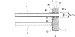
図1aは、軸断面図を利用して、好ましくはエアバッグ点火器もしくは点火装置として使用するための、本発明により形成された金属固定材料ダクト1の好ましく使用される第1の実施形態を具体的に示す。これは、2本の互いに平行の金属ピン4および5が電気的に結合された金属カップシール2を形成する基体3を含む。この両方の金属ピン4および5は、互いに平行に配置されている。その際に一方は導体として、第2の金属ピンはアースに設置される。図示した場合では、第1の金属ピン4が導体として、かつ金属ピン5がアースピンとして機能する。これらの金属ピンの少なくとも一方、特に導体として機能する金属ピン4は、基体3を通して案内される。そのために、金属ピン4は、固定材料34内のその長さlの一部l1、特にガラス溶融物から冷却されたガラス栓6に溶融されている。
FIG. 1a utilizes an axial cross-sectional view to illustrate a first preferred embodiment of a metal
金属ピン4は、少なくとも片側でガラス栓6の前面7から超えて突出し、図示した実施形態では、製造終了後にガラス栓6の第2の前面8と一列に並んで閉じる。そのため、金属ピン4は、連結路開口部11の領域にあり、かつ前面13の領域で固定材料と基体3との間の望ましくない連結の劣化を生じる固定材料の冷却中の凹みを回避するため溶融中に、該金属ピンが基体3と共に前面13上へ突出するように連結路開口部11の中に配置されている。溶融もしくは注入後に金属ピン4および突出する冷却された固定材料の研磨を実施することができ、その結果、この金属ピンが前面13と一列に並び、それによってガラス栓6の前面8も基体3の前面13と一列に並ぶ。その他の変形例も考えることができる。
The
アースピン5は、図示した場合では、直接基体3の裏面12でこの基体に固定される。基体3は本願の意味で打抜き部として形成されている。本願記載の打抜き部は、少なくとも連結路開口部11、好ましくは基体3の最終形状もスタンピングによって製造される場合に存在する。発展した実施形態に従って、外部輪郭を規定する形状によって、特に外周10が切断、好ましくはスタンピングによって製造することができる。打抜き部は、スタンピング工程後に存在するような形状で引き続き使用できるか、あるいは好ましくは直接それに続く別の作業工程で成形、例えばパンチングまたは深絞りすることができる。
In the illustrated case, the
ガラス栓6による金属ピン4の収容と固定のために設けた連結路開口部11は、スタンピング工程によって穴の形状で製造される。それに続き、金属ピン4が金属固定材料ダクト1の裏面12にガラス栓と共に連結路開口部11の中へ挿入され、ガラス栓6および金属ピンを含む金属体が加熱され、その結果、冷却工程後に金属が収縮し、そのようにしてガラス栓6の間で金属ピン4および基体3との摩擦係合連結部が形成される。
The connection path opening 11 provided for receiving and fixing the
溶融もしくは流動性の状態の固定材料34、特にガラス溶融物を前面13から連結路開口部11の中へ取り込むことも考えられる。その場合、冷却中に金属ピン4の外周14と連結路開口部11の内周15との間に形状嵌合および素材対応の連結が生じる。本発明により、基体3は、連結路開口部11の軸方向と垂直に基体3の厚さDと連結路開口部11の最大拡径部との間の比が0.5を含む2.5までの間の範囲になるように形成されている。例えば円形の断面または楕円形の断面によって特徴づけられる連結路開口部11のそれぞれの形成に応じて、最大拡径部は、楕円形の直径dまたは長さによって決定される。この場合、軸方向は幾何学的軸に、特に連結路開口部11の対称軸に相当し、基体3を通して伸長する。好ましくは、打抜き部としての基体3の形成時に、特にコンパクトでコスト的に有利にかつエネルギー効率のよい製造を達成するために、要求された性質、特に点火の解除時に要求される押出力を有する基体3を達成する。
It is also conceivable for the fixing material 34 in the molten or fluid state, in particular the glass melt, to be taken into the connecting channel opening 11 from the
連結路開口部11の軸方向と垂直の基体3の厚さDと連結路開口部11の最大拡径部との間の比は、0.8を含む1.6までの間、好ましくは0.8から1.4の間、特に好ましくは0.9から1.3の間、さらに特に好ましくは1.0から1.2の間の範囲で選択される。これは具体的な寸法表示で、例えば基体3の厚さDが1から(および)5mmの間、好ましくは1.5mmから(および)3.5mmの間、特に好ましくは1.8mmから3.0mmの間、さらに特に好ましくは2.0mmから2.6mmの間になることを意味する。それによって、回動部に対して一方で本質的により小さい構造体が実現され、さらに連結路開口部11の断面をそれぞれの要件に応じて任意に選択することができる。
The ratio between the thickness D of the
図1bおよび1cの表1および表2に、円形の穴径すなわち連結路開口部の直径の絶対値ならびに連結路開口部を含む基体の厚さならびにそこから生じる穴径と厚さの比が表示されている。表1に、図1bに準じて、研磨工程後の基体の厚さの値に対する穴径の値を表示している。上記のようにガラス栓の突部を研磨するために利用される研磨工程によって、全構造体の厚さは約0.4mm低減される。表1に穴径は、mmで表示している。表1に記載の穴径は、1.6mmから3.5mmに達する。さらに、研磨後の基体の厚さはmmで表示している。研磨後の基体の厚さは、2.0mmから3.0mmになる。さらに、生じた穴径と厚さの比を表示している。縁取り領域1000は、直径ならびに穴径と厚さの比の好ましい領域を表し、領域1100はさらに好ましい領域を表す。
Tables 1 and 2 in FIGS. 1b and 1c display the circular hole diameter, ie the absolute value of the diameter of the connection path opening, the thickness of the substrate including the connection path opening and the ratio of the hole diameter to the thickness resulting therefrom. Has been. In Table 1, the value of the hole diameter with respect to the value of the thickness of the substrate after the polishing step is displayed according to FIG. 1b. The thickness of the entire structure is reduced by about 0.4 mm by the polishing process used to polish the protrusions of the glass plug as described above. Table 1 shows the hole diameter in mm. The hole diameters listed in Table 1 reach from 1.6 mm to 3.5 mm. Furthermore, the thickness of the substrate after polishing is indicated in mm. The thickness of the substrate after polishing is changed from 2.0 mm to 3.0 mm. Furthermore, the ratio of the hole diameter and thickness which arose is displayed. The
図1cの表2に、スタンピング後の、ただし研磨工程前の基体の厚さをmmで表示しており、穴径は、mmで表示している。さらに、穴径と厚さの比を表示している。ここでも好ましい領域は、1000で表し、さらに好ましい領域は、1100で表す。 In Table 2 of FIG. 1c, the thickness of the substrate after stamping but before the polishing step is indicated in mm, and the hole diameter is indicated in mm. Furthermore, the ratio of the hole diameter to the thickness is displayed. Again, a preferred region is represented by 1000 and a more preferred region is represented by 1100.
点火時の全金属固定材料ダクト1の負荷時に、基体3からのガラス栓6を有し、また連結路開口部11の短縮により生じた小さい支持面を有する金属ピン4の弛緩を回避するため、ここに35で表示した裏面12の方向への固定材料34と連結路開口部の内周15との間の相対運動を阻止する阻止手段を設けている。これは、まるで逆鉤体として機能し、ガラス栓6および/または金属ピン4への引張力作用および/または圧縮下に基体3とガラス栓6との間に形状嵌合を生ぜしめ、それによって裏面12での滑落を阻止する。そのために、特に好ましい第1の実施形態に従って、連結路開口部11が突部37によって形成されるアンダーカット部36を有するように該開口部が形成されている。
In order to avoid loosening of the
このアンダーカット部は、裏面12の領域に配置され、図示した場合においてこの裏面と一列に並ぶ。図示した場合で好ましくは円形の断面で形成された連結路開口部11は、この突部37によって2つの異なる直径d1およびd2を特徴とする。その際、直径d1は、直径d2よりも大きい。直径d2は、裏面12での連結路開口部11の直径である。直径d1は、前面13での連結路開口部11の直径である。ここで連結路開口部11は、その伸長部ld1の本質的な部分にわたって等しい直径d1で形成されている。ld2は、直径d2を有する連結路開口部11の形成を表す。
The undercut portion is disposed in the region of the
すなわち、連結路開口部は、2つの部分領域、一方が第1の部分領域16および他方が第2の部分領域17を有し、第1の部分領域16は、直径d1によって、かつ第2の部分領域17は、直径d2によって特徴づけられる。その際、前記直径は、片側のスタンピング工程によって穴の形態で前面13または裏面12の側からそれに続く圧力作用下の成形工程、特にパンチングによって製造される。
That is, the connection path opening has two partial regions, one having a first
好ましくは、スタンピング工程および成形工程は、それぞれ同じ側から、図示した場合では、例えば前面13から行われる。好ましくは基体3の切断は、特に好ましい実施形態において、同様に連結路開口部11のスタンピング工程で、すなわち同じ作業工程の枠内で行われる。そのため金型は、その際に全基体3が連結路開口部11と共に1つの作業工程で基体3の厚さDに相当する一定の薄板強度bの薄板から打ち抜かれるように考案されている。
Preferably, the stamping step and the molding step are each performed from the same side, for example, from the
本発明により、回動部よりも低減された厚さで高い引出力と共に特にコスト的に有利なかつ材料集中の少ない製造を達成するために、基体3の厚さDと連結路開口部11の寸法との間の上記比が順守される。その際、アンダーカット部36を設けることによって引出力をほぼ倍化させることができる。
According to the invention, in order to achieve a particularly cost-effective and less concentrated material with a high pulling force with a reduced thickness than the pivot part, the thickness D of the
本発明により、アンダーカット部36と共に突部37は、寸法縮小すなわち差分Δd=d1−d2もしくは最大拡径部の縮小によって0.05から1mmの範囲、0.08から0.9mmの範囲、好ましくは0.1から0.3mmの範囲で特徴づけられる断面縮小が部分領域17に製造されるように形成されている。アンダーカット部36および突部37に至る直径の差分Δd=d1−d2は、回動部としての実施形態に比べ短縮された構造方式と共に連結路開口部11の短縮された長さを打抜き部としての形成時に調整するために充分であり、押出力がさらに増大される。
According to the present invention, the projecting
基体用の材料として、好ましくは金属、特にSt35、St37、St38のような普通鋼または特殊鋼もしくはステンレス鋼が使用される。DIN EN10020による特殊鋼は、合金鋼または非合金鋼の名称であり、それらの硫黄およびリン含有量(いわゆる鉄の随伴物質)は0.035%を超えない。しばしば、その後に別の熱処理(例えば焼鈍)が設けられている。特殊鋼には、例えば高純度鋼が含まれており、前記鋼の場合、特別の製造工程によってアルミニウムおよびシリコーンのような成分が溶融物から析出され、さらに、後の熱処理用に考慮した高合金工具鋼も含まれる。例えば次のものを使用できる。すなわち、X12CrMoS17、X5CrNi1810、XCrNiS189、X2CrNi1911、X12CrNi177、X5CrNiMo17−12−2、X6CrNiMoTi17−12−2、X6CrNiTi1810およびX15CrNiSi25−20、X10CrNi1808、X2CrNiMo17−12−2、X6CrNiMoTi17−12−2である。 The material for the substrate is preferably a metal, in particular ordinary steel such as St35, St37, St38 or special steel or stainless steel. Special steel according to DIN EN10020 is the name of alloy steel or non-alloy steel, and their sulfur and phosphorus content (so-called iron companions) does not exceed 0.035%. Often, another heat treatment (eg, annealing) is subsequently provided. The special steel includes, for example, high-purity steel, and in the case of the steel, components such as aluminum and silicone are precipitated from the melt by a special manufacturing process, and the high alloy is considered for later heat treatment. Tool steel is also included. For example, the following can be used. That is, X12CrMoS17, X5CrNi1810, XCrNiS189, X2CrNi1911, X12CrNi177, X5CrNiMo17-12-2, X6CrNiMoTi17-12-2, X6CrNiTi1810, and X15CrNiSi25-20, X10CrNi1808, X2CrNiMo17-12-2, X6CrNiMo-212, X6CrNiMo—
上記材料、特に表示した工具鋼の長所は、これらの材料の使用時に、高い耐腐食性、高い機械的強度ならびに良好な溶接性が保証されることである。 The advantage of the above-mentioned materials, in particular the indicated tool steels, is that high corrosion resistance, high mechanical strength and good weldability are guaranteed when these materials are used.
図1aに示した実施形態の場合、連結路開口部11は、円形の断面を有する。しかしながら、別の形状も考えることができ、その場合は、アンダーカット部が開口の内部寸法の変更によって形成される。さらに、図示した形状は、理想的に記載されている。つまり、実際上、(通常)、相互に完全に直角になる平面領域は生じない。決定的なことは、一方で溶融された金属ピンの収容と、さらに金属ピンおよび阻止手段(固定手段)、特にガラス栓からなる全体の脱落運動の阻止に好適である連結路開口部の基本輪郭が作られることであり、すなわちアンダーカット部を形成する平面領域と隣接する平面領域は、互いに1つの角度で配置することができる。
In the case of the embodiment shown in FIG. 1a, the connecting
図2は、連結路開口部11の一部のみを円錐形に形成した実施形態を開示する。この実施形態において、金属固定材料ダクト1の連結路開口部11は、特に基体3の中で同様に2つの部分領域、つまり第1の部分領域16と第2の部分領域17とに分割されている。その際、第2の部分領域17は、その全長ld2にわたり一定の直径d2を特徴とする。第2の部分領域は、ここで裏面12から前面13方向へ伸長する。第1の部分領域16は、連結路開口部11の連続する断面縮小を特徴とする。前記縮小は、直径d1ないし直径d2まで行われる。図1aおよび2の実施形態による裏面12で縮小された直径は、長所として、金属ピン5、特にアースピンに対してより大きい接続面18を提供する。アンダーカット部36は、第2の部分領域17から第1の部分領域16の方向に見た直径の変化によって生じる。
FIG. 2 discloses an embodiment in which only a part of the connection path opening 11 is formed in a conical shape. In this embodiment, the connection path opening 11 of the metal fixing
図1aおよび2に示した全ての実施形態において、連結路開口部11の非対称の形状は、前面13から裏面12の方向に見て、長所として、裏面12もしくはこの裏面方向へのガラス栓6の滑落または引外しの阻止を提供する。さらに、非対称の形状による組立中に、個々の要素、特に金属ピン4および5の組込位置に対してより容易な方向づけを付与することができる。このアンダーカット部によって、点火時に基体からの金属ピン4およびガラス栓6からなる構造ユニットの脱落が回避される。裏面12の付加的な材料は、長所として、アース上に設置される金属ピン4、5に対してより大きい接続面を提供する。さらに、この接続面は、正面への圧力作用時に金属ピンのガラスシールの強度を増大する。
In all the embodiments shown in FIGS. 1 a and 2, the asymmetrical shape of the connecting
図3は、本発明に係る金属固定材料ダクト1のさらなる実施形態を具体的に示す。この実施形態において、連結路開口部11は3つの部分領域20、21および22に分割可能であり、それぞれ第1および第3の部分領域20および22は、好ましくは等しい直径d20およびd22を特徴とする。第2の部分領域21は、直径d20およびd22よりも小さい直径d21を特徴とし、それによって突部23を形成する。この突部は、連結路開口部11の内周15に対して裏面12の方向へのガラス栓6の相対運動を阻止するために正面と裏面との間の中心に配置されたアンダーカット部36を形成する。
FIG. 3 specifically shows a further embodiment of the metal fixing
特に、それぞれ前面13および裏面12に向けた平面24および25は、その際に軸線方向のガラス栓6用の係止面を形成する。この実施形態は、両方向へのガラス栓6の固定を特徴とし、その結果、この基体の形成は、特に好ましくは、任意の組込みおよび位置決めが可能という点で好適であり、これは特に金属ピン4の連結に関係する。この実施形態は、ガラス栓6を圧縮負荷で前記ガラス栓の部分の剪断下に移動させる押出力の上昇を規定する。
In particular, the
上記の全ての解決策において、ガラス栓6によって限定されたシールの等しいまたは増大した強度によって従来の技術から公知の解決策よりも狭い基体3を使用することが可能になる。
In all the above solutions, the equal or increased strength of the seal limited by the
図3に記載の基体3の製造は、一定の直径を有する連結路開口部11を備える基体3のスタンピングによって行われる。突部は、所定のパンチング深さと、スタンピング後に存在する連結路開口部11の直径よりも大きい直径を有するパンチング工具とを用いる両面パンチングによって達成される。流動限界を超えるときパンチング工具の影響による基体3での材料の表面張力の上昇によって、そこで突部23を形成する材料の流れが生じる。その際、パンチング工程が最初に基体の正面または裏面から生じるかどうかは重要ではない。しかしながら、所望の対称構造の場合、パンチング力とパンチング深さが両面で等しく選択されるべきである。
The
図1aないし3は、基体3での措置、特に連結路開口部に対するガラス栓6の相対運動を阻止する連結路開口部11を具示しているが、図4および5は、試験中およびさらに点火過程中のガラス栓6からの金属ピン4の流出の阻止に利用される金属ピン4での措置を例示する。ガラス栓内の金属ピンの強度は、引出力によって特徴づけられる。この措置は、単独または(しかし)別の手段35と組み合わせて使用することができる。
FIGS. 1a to 3 show a connection path opening 11 which prevents the action on the
その際、図4は、図1に示した金属ピン4の付加的な変更を含む実施形態の特に好ましい組合せを示す。ピン4は、ここで基体3との結合領域に少なくとも1つの突部を有し、この突部は、31で表示されており、ピン4の外周32の周りに周方向へ伸長する。この図示した実施形態は、金属ピン4の全外周32の周りに伸長する突部31である。これは、金属ピン4の突押しまたは圧搾によって形成することができる。別のここに図示しない可能性は、基体3内の結合領域に金属ピン4に複数の互いに円周方向に隣接した、好ましくは互いに等間隔で隣接させて配置した突部の配置を含む。前記金属ピン4での突部の特徴は、本質的に連結強度の改善に寄与する。この特徴は、通常ガラス栓の引張負荷および取出し時に金属ピンが機能停止する相応の試験中の金属ピン4の取外しを阻止する。
In doing so, FIG. 4 shows a particularly preferred combination of embodiments comprising additional modifications of the
これは、類比的に図5に記載の実施形態にも当てはまる。この場合、金属ピン4はガラス溶融物との接触領域に連結路開口部の軸線方向の伸長部にわたって配置した複数の突部を有し、これらの突部は、順々に連結されている。その際、最も簡単な場合では波形33が使用される。この波形により、図4に記載されたものと同様の効果を達成することができる。その他の構造は、図4に記載されたものに相当し、そのため同じ要素には同じ符号を使用している。
This applies analogously to the embodiment described in FIG. In this case, the
さらに、図4および5に記載した実施形態は、図2に示した基体での措置、特に連結路開口部と組み合わせることができる。 Furthermore, the embodiment described in FIGS. 4 and 5 can be combined with the measures on the substrate shown in FIG. 2, in particular the connection channel opening.
図6は、大幅に簡略化した図示で、図1ないし4を利用して記載したように、金属固定材料ダクト1を備える点火装置38の軸断面図を具体的に例示する。点火装置38はこの種のダクトの使用下に火薬装填物40を封入して基体3とのキャップ39の連結によって構築され、その際ここに例示した溶接縁部でレーザー全周溶接継目41で連結される。それによって、気密に密閉された火薬装填物用のハウジング42が製造される。
FIG. 6 is a greatly simplified illustration and specifically illustrates an axial cross-sectional view of an
さらに、図6は、金属固定材料ダクト1およびキャップ39の連結前または連結時に導電性の金属ピン4およびキャップ39または基体3に接続される点火ブリッジ43を示す。例えば、点火ブリッジ43は、基体3にそれぞれスポット溶接を利用して固定されるグローワイヤとして形成することができる。大幅に簡略化した図6の図示と異なり、火薬装填物40に加えてさらに点火ブリッジ43を囲む早期点火剤が多数使用されている。
Further, FIG. 6 shows an
図7は、点火装置38内の本発明に係る金属固定材料ダクト1の適用による別の実施形態の断面部分を示す。この場合、基体3の溶接縁部は、図6に示した例のように軸線方向に伸長せず、基体3の半径方向に伸長し、この基体の周りに円周方向に周回する。溶接縁部は、キャップ39の載置時の係止部を形成し、その結果、このキャップは非常に容易に正確に位置決め可能である。溶接縁部は、好ましい仕方で深絞りによって、または好ましく打ち抜かれた基体3の押出成形によって得ることができる。
FIG. 7 shows a cross-sectional part of another embodiment with the application of the metal fixing
上記実施例は、好ましくは平行に配置された2本の金属ピンを含み、それらのうち金属ピンの一方が基体の裏面でアースに設置された金属固定材料ダクトもしくはガラス金属ダクトにすべて、関係し、本発明は原理的に2本以上の金属ピンと、いわゆるモノピンにも適用可能である。モノピンは、ピン支持体によって担持される1本の金属ピンのみを含む点火ユニットである。ピン支持体自体は、例えばアース接続部を形成する金属リングを含む。 The above embodiment involves two metal pins, preferably arranged in parallel, one of which is all related to a metal fixing material glass or glass metal duct, one of which is installed at ground on the back of the substrate. In principle, the present invention is also applicable to two or more metal pins and so-called mono pins. A monopin is an ignition unit that includes only one metal pin carried by a pin support. The pin support itself includes, for example, a metal ring that forms a ground connection.
この種のモノピンは、図8に示している。ピン支持体26は、好ましくはガラスから形成される絶縁された充填部6の中に埋め込まれる金属ピン4を含む。ピン支持体26は、金属ピン4を収容する基体3と、内部の壁面28を有するスリーブ27とを含む。金属ピン4の溶融部の端部は、ブリッジ29を利用して基体3と導電性に接続されている。連結路開口部11は、基体3の中にスタンピング工程によって取り込まれている。好ましい一実施形態において、連結路開口部11と共に基体3が前記のように打ち抜くことができる。さらに特に好ましくは、基体3がスリーブ27と共に一体の構成部材を形成する。一体の構成部材の製造は、例えば打抜き部を一方法工程で打ち抜き、かつスリーブを深絞りによって得ることによって行うことができる。連結路開口部の大きさと、基体の厚さの寸法決定は、上述のように行われる。
This type of monopin is shown in FIG. The
好ましくは、スリーブ27の内部の壁面28ならびに金属ピン4の自由端が被覆される。被覆材料として、例えば金が使用される。前記被覆は、好ましくは電気分解法で塗布される。前記被覆は、スリーブの中に挿入されるプラグ31と、スリーブ27の壁面(内側)28との間の移行部30での電気抵抗を小さく保持するために用いられる。
Preferably, the
図9は、断面図であり、図9に断面図で図示していない点火装置38を備えるパイロ技術の保護装置のガス発生器45を示す。ガス発生器45は、特にステアリングホイールのエアバッグに使用することができ、そのためステアリングホイールの衝撃吸収体の中に組み込まれている。点火装置38は、ガス発生器45の中央空間部46の中に挿入される。点火装置38は、例えば中央空間部46の出口に取り付けるためのフランジ47を有する。中央空間部46は、例えばタブレット形に圧縮されたアジ化ナトリウム、窒化カリウムおよび砂からなる火薬装填物として設けた火薬装填物を含む環状の火薬装填物容器49を有する通路48に連結されている。この発射火薬は、点火時に爆発的に点火装置38から出るガスによって着火され、該点火装置側で推進ガスを解放し、このガスが通路50を通り外方へ流出し、かつ、例えば固定リム51に固定されたエアバッグを膨張する。
FIG. 9 is a cross-sectional view showing a pyrotechnic protection device gas generator 45 with an
図1aないし9に図示した全ての実施形態において、少なくとも連結路開口部は、好ましくは全体的に従来の技術で回動部として形成された基体3が打抜き部に置換される。個々の図で基体3に、かつ固定材料からの金属ピンの引外しを回避するために金属ピンに設けた、負荷による基体からの金属ピン4の引外しを回避する個別的な措置は、互いに組み合わせて適用することもできる。この点に関して、この実施形態は、いかなる制限も受けない。しかしながら、目指しているのは、金属ピン4と基体3との間の全連結部と共に金属固定材料ダクト1の高い強度を保証する実施形態である。
In all the embodiments illustrated in FIGS. 1 a to 9, at least the connection path opening is preferably replaced by a punched part, which is generally entirely formed as a pivot part in the prior art. The individual measures provided on the
図示した全ての実施形態において、異なる断面形状を有する連結路開口部を形成することができる。しかしながら、好ましくは円形の断面が選択される。アンダーカット部の形成は、基体の集積構成部材として行われる。 In all the illustrated embodiments, connection path openings having different cross-sectional shapes can be formed. However, preferably a circular cross section is selected. The undercut portion is formed as an integrated component of the substrate.
本発明の功績は、金属固定材料ダクトを打抜き部として、特に連結路開口部をスタンピングによって形成できるようにするため、穴径と打抜き部の厚さをどの程度の比にするべきであるかに見出されるべきである。 The achievement of the present invention is that the ratio between the hole diameter and the thickness of the punched portion should be set so that the metal fixing material duct can be used as the punched portion, and in particular, the connection path opening can be formed by stamping. Should be found.
1 金属固定材料ダクト
2 金属カップシール
3 基体
4 金属ピン
5 金属ピン
6 ガラス栓
7 第1の前面
8 第2の前面
9 スタンピング要素
10 外周
11 連結路開口部
12 裏面
13 正面
14 外周
15 内周
16 第1の部分領域
17 第2の部分領域
19 接続面
20 第1の部分領域
21 第2の部分領域
22 第3の部分領域
23 突部
24 平面
25 平面
26 ピン支持体
27 基体のスリーブ
28 スリーブの内部の壁面
29 ブリッジ
30 移行部
31 スリーブの中に挿入されるプラグ
34 固定材料
35 固定材料と連結路開口部の内周との間の相対運動を阻止する阻止手段
36 アンダーカット部
37 突部
38 点火装置
39 キャップ
40 火薬装填物
41 レーザー溶接継目
42 ハウジング
43 点火ブリッジ
44 係止部
45 ガス発生器
46 空間部
47 フランジ
48 通路
49 火薬装填物容器
50 通路
d1 直径
d2 直径
ld1 長さ
ld2 長さ
DESCRIPTION OF
Claims (43)
スタンピング加工により形成される連結路開口部(11)と正面(13)と裏面(12)とを含む基体(3)であって、前記連結路開口部(11)の軸方向に対して垂直な前記連結路開口部(11)の最大寸法に対する前記基体(3)の厚さの比率が約0.5〜2.5の範囲内にあるように構成される基体(3)と、
ガラス栓、セラミック栓またはガラスセラミック栓である固定材料と、
前記固定材料(6)内の前記基体(3)内の前記連結路開口部(11)内に配置される少なくとも1つの第1の金属ピンと、
前記正面と前記裏面との間の構造であって、前記連結路開口部(11)の内部周囲に対して前記裏面へと向かう方向における前記固定材料(6)の相対運動を回避するように構成される構造とを備え、
前記基体(3)は、X12CrMoS17,X5CrNi1810,XCrNiS189,X2CrNi1911,X12CrNi177,X5CrNiMo17−12−2,X6CrNiMoTi17−12−2,X6CrNiTi1810,X15CrNiSi25−20,X10CrNi1808,X2CrN1Mo17−12−2,およびX6CrNiMoTi17のステンレス鋼のうちの1つを含む種類の鋼であり、
前記固定材料(6)と前記連結路開口部(11)との間の相対的運動を回避するために、前記固定材料(6)と前記連結路開口部(11)との間に摩擦係合連結部が提供される、ことを特徴とする金属固定材料ダクト。 A plurality of airbags or one ignition dexterity metal fixing material duct of the belt tensioner (1),
A base body (3) including a connection path opening (11), a front surface (13), and a back surface (12) formed by stamping, and perpendicular to the axial direction of the connection path opening (11) A base body (3) configured such that a ratio of a thickness of the base body (3) to a maximum dimension of the connection path opening (11) is in a range of about 0.5 to 2.5;
A fixing material which is a glass plug, a ceramic plug or a glass ceramic plug;
At least one first metal pin disposed in the connection path opening (11) in the base body (3) in the fixing material (6);
The structure between the front surface and the back surface is configured to avoid the relative movement of the fixing material (6) in the direction toward the back surface with respect to the inner periphery of the connection path opening (11). The structure and
The substrate (3) is made of X12CrMoS17, X5CrNi1810, XCrNiS189, X2CrNi1911, X12CrNi177, X5CrNiMo17-12-2, X6CrNiMoTi17-12-2, X6CrNiTi1810, X15CrNiSi25-20, X10CrNi1808, X2CrN1Mo17Ni2, Ti6Mo17-12 A type of steel containing one of
Friction engagement between the fixing material (6) and the connection path opening (11) to avoid relative movement between the fixing material (6) and the connection path opening (11). A metal fixing material duct, characterized in that a connection is provided .
前記連結路開口部(11)が、2つの部分領域(16、17)として、前記裏面(12)から前記正面(13)方向へ伸長する部分領域(17)と、前記正面(13)から前記裏面(12)方向へ伸長する別の部分領域(16)を有し、
前記突部(37)が、前記裏面(12)から前記正面(13)方向へ伸長する前記部分領域(17)によって形成され、かつ別の前記部分領域(16)よりも小さい内部寸法を有し、
前記両方の部分領域(16、17)が、該部分領域の全長にわたりそれぞれ部分領域内で一定の内部寸法をもつ均一な幾何学的形状を有することを特徴とする、請求項11に記載の金属固定材料ダクト(1)。 Said metal fixing material duct (1),
The connection path opening (11) has two partial regions (16, 17) as a partial region (17) extending from the back surface (12) in the front (13) direction, and from the front (13). Having another partial region (16) extending in the direction of the back surface (12),
The protrusion (37) is formed by the partial region (17) extending from the back surface (12) in the front (13) direction and has an internal dimension smaller than that of the other partial region (16). ,
12. Metal according to claim 11 , characterized in that both partial areas (16, 17) have a uniform geometric shape with a constant internal dimension within each partial area over the entire length of the partial area. Fixed material duct (1).
前記連結路開口部(11)が、2つの部分領域(16、17)として、前記裏面(12)から前記正面(13)方向へ伸長する部分領域(17)と、前記正面(13)から前記裏面(12)方向へ伸長する別の部分領域(16)を有し、
前記突部(37)が、前記裏面(12)から前記正面(13)方向へ伸長する部分領域(17)によって形成され、かつ別の部分領域(16)よりも小さい内部寸法を有し、
前記両方の部分領域(16、17)が、該部分領域の全長にわたり異なる幾何学的形状および/または異なる内部寸法を有することを特徴とする、請求項11に記載の金属固定材料ダクト(1)。 Said metal fixing material duct (1),
The connection path opening (11) has two partial regions (16, 17) as a partial region (17) extending from the back surface (12) in the front (13) direction, and from the front (13). Having another partial region (16) extending in the direction of the back surface (12),
The protrusion (37) is formed by a partial region (17) extending from the back surface (12) to the front (13) direction, and has an internal dimension smaller than another partial region (16);
12. Metal fixing material duct (1) according to claim 11 , characterized in that both partial areas (16, 17) have different geometric shapes and / or different internal dimensions over the entire length of the partial areas. .
両方向へそれぞれ1つの前記アンダーカット部(36)を有し、
前記連結路開口部(11)が、3つの部分領域として、前記裏面(12)から前記正面(13)方向へ伸長する第1の部分領域と、前記第1の部分領域に接続される第2の部分領域と、前記正面(13)から前記裏面(12)方向へ伸長する第3の部分領域とを有し、
前記第2の部分領域が、前記第1の部分領域および前記第3の部分領域よりも小さい前記連結路開口部(11)の寸法になることを特徴とする、請求項10、11、16のいずれか一項に記載の金属固定材料ダクト(1)。 Said metal fixing material duct (1),
Each have one of said undercut portion (36) to both directions,
The connection path opening (11) has three partial areas, a first partial area extending from the back surface (12) in the front (13) direction, and a second connected to the first partial area. And a third partial region extending from the front surface (13) to the back surface (12) direction,
The said second partial area has a dimension of said connection path opening (11) smaller than said first partial area and said third partial area, according to claim 10, 11, 16 Metal fixing material duct (1) as described in any one of Claims.
Applications Claiming Priority (1)
| Application Number | Priority Date | Filing Date | Title |
|---|---|---|---|
| DE102006004036A DE102006004036A1 (en) | 2006-01-27 | 2006-01-27 | Metal fixing material implementation and use of such a passage and airbag and belt tensioner with an ignition device |
Publications (2)
| Publication Number | Publication Date |
|---|---|
| JP2007198724A JP2007198724A (en) | 2007-08-09 |
| JP4521000B2 true JP4521000B2 (en) | 2010-08-11 |
Family
ID=37998453
Family Applications (1)
| Application Number | Title | Priority Date | Filing Date |
|---|---|---|---|
| JP2007008769A Active JP4521000B2 (en) | 2006-01-27 | 2007-01-18 | Air bag and belt tensioner with metal fixing material duct and the use of such a duct and ignition device |
Country Status (9)
| Country | Link |
|---|---|
| US (1) | US8127681B2 (en) |
| EP (4) | EP3104114B1 (en) |
| JP (1) | JP4521000B2 (en) |
| AT (1) | ATE506593T1 (en) |
| DE (2) | DE102006004036A1 (en) |
| ES (1) | ES2617504T3 (en) |
| HU (1) | HUE032923T2 (en) |
| MX (1) | MXPA06013611A (en) |
| PL (1) | PL2270417T3 (en) |
Families Citing this family (25)
| Publication number | Priority date | Publication date | Assignee | Title |
|---|---|---|---|---|
| DE102006004036A1 (en) | 2006-01-27 | 2007-08-09 | Schott Ag | Metal fixing material implementation and use of such a passage and airbag and belt tensioner with an ignition device |
| US8327765B2 (en) | 2003-03-03 | 2012-12-11 | Schott Ag | Metal fixing material bushing and method for producing a base plate of a metal fixing material bushing |
| US8733250B2 (en) | 2006-01-27 | 2014-05-27 | Schott Ag | Metal-sealing material-feedthrough and utilization of the metal-sealing material feedthrough with an airbag, a belt tensioning device, and an ignition device |
| DE102006056077A1 (en) * | 2006-11-28 | 2008-05-29 | Schott Ag | Ignition device for a pyrotechnic protection device |
| DE102009008673B3 (en) * | 2009-02-12 | 2010-08-19 | Schott Ag | Punched feedthrough element with soldered contact pin |
| DE102010045641A1 (en) | 2010-09-17 | 2012-03-22 | Schott Ag | Process for producing a ring-shaped or plate-shaped element |
| US10684102B2 (en) | 2010-09-17 | 2020-06-16 | Schott Ag | Method for producing a ring-shaped or plate-like element |
| HUE044117T2 (en) * | 2010-09-17 | 2019-10-28 | Schott Ag | Glass-to-fixing-material seal and method for manufacturing the same |
| DE102010045624C5 (en) | 2010-09-17 | 2018-10-04 | Schott Ag | Ring or plate-shaped element |
| CN106392761A (en) * | 2010-12-21 | 2017-02-15 | 必诺·罗伊泽有限及两合公司 | Rotary feed-through |
| AT513505B1 (en) * | 2012-10-25 | 2014-05-15 | Electrovac Hacht & Huber Gmbh | Method of manufacturing a firing base for pyrotechnic systems and firing bases for pyrotechnic systems |
| AT513921B1 (en) * | 2013-01-23 | 2015-05-15 | Electrovac Hacht & Huber Gmbh | igniter receptacle |
| AT515349B1 (en) * | 2014-01-30 | 2015-11-15 | Electrovac Hacht & Huber Gmbh | Method of making a lighter socket |
| DE102017124292A1 (en) * | 2017-10-18 | 2019-04-18 | Trw Airbag Systems Gmbh | LIGHTER FOR A GAS GENERATOR AND METHOD FOR PRODUCING A LIGHTER |
| DE102018105445A1 (en) * | 2018-03-09 | 2019-09-12 | Benteler Steel/Tube Gmbh | Housing of a gas generator module for an airbag system of a motor vehicle |
| DE102018005733B4 (en) * | 2018-07-20 | 2021-01-14 | Schott Ag | Glass-to-metal bushing |
| DE102018218001B4 (en) | 2018-10-22 | 2021-09-30 | Schott Ag | Method for producing a connection pin for bushings, as well as connection pin |
| DE102019208035B4 (en) * | 2019-06-03 | 2021-10-14 | Schott Ag | Glass-to-metal bushing with a sleeve |
| EP3839413B1 (en) * | 2019-12-19 | 2022-03-16 | Schott Ag | Metal fixing material feedthrough, method for the production and uses thereof |
| DE102020107224A1 (en) * | 2020-03-17 | 2021-09-23 | Schott Ag | Electrical facility |
| JP2023523347A (en) | 2020-04-28 | 2023-06-02 | ショット アクチエンゲゼルシャフト | Personnel protection device igniter and method of manufacture |
| EP3904822A1 (en) | 2020-04-28 | 2021-11-03 | Schott AG | Igniter for personal protection devices and method of manufacture |
| DE202020102354U1 (en) | 2020-04-28 | 2021-07-29 | Schott Ag | Ignitors of personal protection devices |
| EP4102518A1 (en) * | 2021-06-08 | 2022-12-14 | Schott Ag | Electrical feedthrough |
| USD1009943S1 (en) * | 2022-03-22 | 2024-01-02 | Schott Ag | Air bag detonator |
Citations (2)
| Publication number | Priority date | Publication date | Assignee | Title |
|---|---|---|---|---|
| JP2004264016A (en) * | 2003-03-03 | 2004-09-24 | Carl-Zeiss-Stiftung | Metal fixing material bush, and manufacturing method for core material thereof |
| JP2006275503A (en) * | 2005-03-03 | 2006-10-12 | Schott Ag | Ignitor for automobile occupant crash protection device |
Family Cites Families (37)
| Publication number | Priority date | Publication date | Assignee | Title |
|---|---|---|---|---|
| BE632157A (en) * | 1962-05-10 | |||
| US3274937A (en) * | 1963-04-11 | 1966-09-27 | Physical Sciences Corp | Detonation squib |
| US3635067A (en) | 1969-09-24 | 1972-01-18 | Honeywell Inc | Apparatus and method for fine blanking of parts |
| DE2159531C3 (en) * | 1971-12-01 | 1980-11-13 | N.V. Philips' Gloeilampenfabrieken, Eindhoven (Niederlande) | Metal-ceramic implementation |
| US3971320A (en) * | 1974-04-05 | 1976-07-27 | Ici United States Inc. | Electric initiator |
| DE2904174C2 (en) * | 1979-02-05 | 1984-01-26 | Heko - Elektronik GmbH & Co KG, 2804 Lilienthal | Electric ignition unit |
| DE3414625A1 (en) | 1983-04-21 | 1984-10-25 | H.F. & Ph.F. Reemtsma Gmbh & Co, 2000 Hamburg | Process for improving the filling properties of tobacco |
| DE3415625A1 (en) * | 1984-04-26 | 1985-10-31 | Dynamit Nobel Ag, 5210 Troisdorf | Electrical detonating element having a desired spark gap |
| DE3606364A1 (en) * | 1986-02-27 | 1987-09-03 | Dynamit Nobel Ag | ELECTRIC IGNITION BRIDGE FOR THE APPLICATION OF APPLICATION SETS, DELAY SETS AND PYROTECHNICAL MIXTURES, AND FOR THE PRIMING OF PRIMARY IGNITION SUBSTANCES AND SETS AND METHOD FOR THE PRODUCTION THEREOF |
| US5367125A (en) * | 1989-01-20 | 1994-11-22 | Dassault Electronique | Aluminum based article having an insert with vitreous material hermetically sealed thereto |
| FR2642257B1 (en) * | 1989-01-20 | 1996-05-24 | Dassault Electronique | GLASS-ALUMINUM SEALING PROCESS, PARTICULARLY FOR ELECTRICAL THROUGHING OF HYBRID CIRCUIT BOX, CORRESPONDING COMPOSITE OBJECT AND GLASS COMPOSITION |
| US5016461A (en) | 1989-09-01 | 1991-05-21 | Hydro-Craft, Inc. | Method and apparatus for stamping weld adapters |
| US5404263A (en) * | 1992-08-27 | 1995-04-04 | Oea, Inc. | All-glass header assembly used in an inflator system |
| JP2700100B2 (en) * | 1993-05-28 | 1998-01-19 | 日本工機株式会社 | Igniter |
| US6274252B1 (en) * | 1994-08-04 | 2001-08-14 | Coors Ceramics Company | Hermetic glass-to-metal seal useful in headers for airbags |
| US5621183A (en) * | 1995-01-12 | 1997-04-15 | Trw Inc. | Initiator for an air bag inflator |
| US5732634A (en) * | 1996-09-03 | 1998-03-31 | Teledyne Industries, Inc. | Thin film bridge initiators and method of manufacture |
| US5988069A (en) * | 1996-11-12 | 1999-11-23 | Universal Propulsion Company, Inc. | Electric initiator having a sealing material forming a ceramic to metal seal |
| US6150961A (en) * | 1998-11-24 | 2000-11-21 | International Business Machines Corporation | Automated traffic mapping |
| DE19927233A1 (en) * | 1999-06-15 | 2001-01-11 | Schott Glas | Glass-metal feedthrough |
| WO2001031281A1 (en) * | 1999-10-28 | 2001-05-03 | Daicel Chemical Industries, Ltd. | Electric type initiator and gas generator |
| US6480783B1 (en) * | 2000-03-17 | 2002-11-12 | Makor Issues And Rights Ltd. | Real time vehicle guidance and forecasting system under traffic jam conditions |
| JP4064044B2 (en) * | 2000-08-29 | 2008-03-19 | 三菱電機株式会社 | Traffic information transmission system, traffic information collection and distribution system, and traffic information collection and distribution method |
| US20020069781A1 (en) * | 2000-12-07 | 2002-06-13 | Vahan Avetisian | Recessed glass header for pyrotechnic initiators |
| US7124688B2 (en) | 2000-12-08 | 2006-10-24 | Special Devices, Inc. | Overmolded body for pyrotechnic initiator and method of molding same |
| WO2002088619A1 (en) * | 2001-04-27 | 2002-11-07 | Daicel Chemical Industries, Ltd. | Initiator assembly and gas generator using the same |
| DE10133223A1 (en) * | 2001-07-09 | 2002-10-17 | Trw Airbag Sys Gmbh & Co Kg | Pyrotechnic igniter for air bag deployment has section of casing engaging recess to form catch connection |
| US6801837B2 (en) * | 2002-01-03 | 2004-10-05 | Meritor Light Vehicle Technology, Llc | Intervehicle network communication system |
| JP2003285712A (en) * | 2002-03-29 | 2003-10-07 | Toyota Motor Corp | Initiator |
| US20030192446A1 (en) * | 2002-04-16 | 2003-10-16 | Paul Berg | Header with overlying eyelet |
| US6877431B2 (en) * | 2002-10-21 | 2005-04-12 | Schott Glas | Hermetically sealed electrical feed-through device with a bent isolated pin in a circular glass seal |
| US6907827B2 (en) * | 2002-11-14 | 2005-06-21 | Special Devices, Inc. | Pyrotechnic initiator having output can with encapsulation material retention feature |
| DE102006004036A1 (en) | 2006-01-27 | 2007-08-09 | Schott Ag | Metal fixing material implementation and use of such a passage and airbag and belt tensioner with an ignition device |
| DE20314580U1 (en) * | 2003-03-03 | 2004-08-05 | Schott Glas | Metal-glass fastening equipment lead-through for airbag or seat belt tension triggers has metal pins in a through-opening and a main body with front and rear sides and a release action |
| US8327765B2 (en) | 2003-03-03 | 2012-12-11 | Schott Ag | Metal fixing material bushing and method for producing a base plate of a metal fixing material bushing |
| DE102004004748A1 (en) * | 2003-03-08 | 2004-09-23 | Dynamit Nobel Ais Gmbh Automotive Ignition Systems | Pyroelectric igniter for explosive charge has housing containing capsule with glass filling, support bridge and ignition charge, and has electrical conductor rods embedded in glass |
| JP2005001601A (en) * | 2003-06-13 | 2005-01-06 | Takata Corp | Gas generator |
-
2006
- 2006-01-27 DE DE102006004036A patent/DE102006004036A1/en not_active Withdrawn
- 2006-10-17 HU HUE10009062A patent/HUE032923T2/en unknown
- 2006-10-17 AT AT06021694T patent/ATE506593T1/en active
- 2006-10-17 PL PL10009062T patent/PL2270417T3/en unknown
- 2006-10-17 ES ES10009062.0T patent/ES2617504T3/en active Active
- 2006-10-17 EP EP16178996.1A patent/EP3104114B1/en active Active
- 2006-10-17 EP EP20100002045 patent/EP2187162B1/en active Active
- 2006-10-17 DE DE502006009342T patent/DE502006009342D1/en active Active
- 2006-10-17 EP EP10009062.0A patent/EP2270417B1/en active Active
- 2006-10-17 EP EP06021694A patent/EP1813906B1/en active Active
- 2006-11-23 MX MXPA06013611A patent/MXPA06013611A/en active IP Right Grant
-
2007
- 2007-01-18 JP JP2007008769A patent/JP4521000B2/en active Active
- 2007-01-25 US US11/627,173 patent/US8127681B2/en active Active
Patent Citations (2)
| Publication number | Priority date | Publication date | Assignee | Title |
|---|---|---|---|---|
| JP2004264016A (en) * | 2003-03-03 | 2004-09-24 | Carl-Zeiss-Stiftung | Metal fixing material bush, and manufacturing method for core material thereof |
| JP2006275503A (en) * | 2005-03-03 | 2006-10-12 | Schott Ag | Ignitor for automobile occupant crash protection device |
Also Published As
| Publication number | Publication date |
|---|---|
| US8127681B2 (en) | 2012-03-06 |
| JP2007198724A (en) | 2007-08-09 |
| DE502006009342D1 (en) | 2011-06-01 |
| DE102006004036A1 (en) | 2007-08-09 |
| EP2270417A2 (en) | 2011-01-05 |
| EP2187162A2 (en) | 2010-05-19 |
| EP1813906B1 (en) | 2011-04-20 |
| HUE032923T2 (en) | 2017-11-28 |
| PL2270417T3 (en) | 2017-06-30 |
| US20070187934A1 (en) | 2007-08-16 |
| EP2270417A3 (en) | 2011-11-16 |
| EP3104114A1 (en) | 2016-12-14 |
| EP2187162B1 (en) | 2015-04-29 |
| EP2270417B1 (en) | 2016-11-30 |
| MXPA06013611A (en) | 2008-10-24 |
| ATE506593T1 (en) | 2011-05-15 |
| ES2617504T3 (en) | 2017-06-19 |
| EP3104114B1 (en) | 2018-03-14 |
| EP2187162A3 (en) | 2010-09-08 |
| EP1813906A1 (en) | 2007-08-01 |
Similar Documents
| Publication | Publication Date | Title |
|---|---|---|
| JP4521000B2 (en) | Air bag and belt tensioner with metal fixing material duct and the use of such a duct and ignition device | |
| KR101895248B1 (en) | Ring or plate shape element, and manufacturing method thereof | |
| JP5512911B2 (en) | Ignition device for automobile occupant protection device | |
| JP5450146B2 (en) | Molded conductive element with soldered contact bar | |
| US8276514B2 (en) | Metal fixing material bushing and method for producing a base plate of a metal fixing material bushing | |
| JP2006275503A5 (en) | ||
| JP6181096B2 (en) | Metal fixing material bush and method of manufacturing core material of metal fixing material bush | |
| TWI488700B (en) | Ring or sheet element manufacturing method | |
| US7267056B2 (en) | Initiator | |
| US8733250B2 (en) | Metal-sealing material-feedthrough and utilization of the metal-sealing material feedthrough with an airbag, a belt tensioning device, and an ignition device | |
| KR102204062B1 (en) | Gas generator | |
| JP2661830B2 (en) | Apparatus and method for inflating a vehicle occupant restraint | |
| JP5073337B2 (en) | Igniter assembly | |
| US7263929B2 (en) | Initiator | |
| JP2015157586A (en) | gas generator | |
| JP4916992B2 (en) | Inflator | |
| JPH1199899A (en) | Pyrotechnic means of vehicle occupant protective device | |
| CN116056783A (en) | Ignition device assembly and ignition device | |
| JP2011218932A (en) | Gas generator | |
| JP4758849B2 (en) | Gas generator | |
| JP4315465B1 (en) | Inflator case for airbag | |
| KR100760887B1 (en) | Metal fixing material bushing socket and method of manufacturing base body of the same |
Legal Events
| Date | Code | Title | Description |
|---|---|---|---|
| A131 | Notification of reasons for refusal |
Free format text: JAPANESE INTERMEDIATE CODE: A131 Effective date: 20090630 |
|
| A601 | Written request for extension of time |
Free format text: JAPANESE INTERMEDIATE CODE: A601 Effective date: 20090929 |
|
| A602 | Written permission of extension of time |
Free format text: JAPANESE INTERMEDIATE CODE: A602 Effective date: 20091002 |
|
| A601 | Written request for extension of time |
Free format text: JAPANESE INTERMEDIATE CODE: A601 Effective date: 20091026 |
|
| A602 | Written permission of extension of time |
Free format text: JAPANESE INTERMEDIATE CODE: A602 Effective date: 20091029 |
|
| A601 | Written request for extension of time |
Free format text: JAPANESE INTERMEDIATE CODE: A601 Effective date: 20091127 |
|
| A602 | Written permission of extension of time |
Free format text: JAPANESE INTERMEDIATE CODE: A602 Effective date: 20091202 |
|
| A521 | Request for written amendment filed |
Free format text: JAPANESE INTERMEDIATE CODE: A523 Effective date: 20091204 |
|
| TRDD | Decision of grant or rejection written | ||
| A01 | Written decision to grant a patent or to grant a registration (utility model) |
Free format text: JAPANESE INTERMEDIATE CODE: A01 Effective date: 20100518 |
|
| A01 | Written decision to grant a patent or to grant a registration (utility model) |
Free format text: JAPANESE INTERMEDIATE CODE: A01 |
|
| A61 | First payment of annual fees (during grant procedure) |
Free format text: JAPANESE INTERMEDIATE CODE: A61 Effective date: 20100521 |
|
| FPAY | Renewal fee payment (event date is renewal date of database) |
Free format text: PAYMENT UNTIL: 20130528 Year of fee payment: 3 |
|
| R150 | Certificate of patent or registration of utility model |
Ref document number: 4521000 Country of ref document: JP Free format text: JAPANESE INTERMEDIATE CODE: R150 Free format text: JAPANESE INTERMEDIATE CODE: R150 |
|
| R250 | Receipt of annual fees |
Free format text: JAPANESE INTERMEDIATE CODE: R250 |
|
| R250 | Receipt of annual fees |
Free format text: JAPANESE INTERMEDIATE CODE: R250 |
|
| R250 | Receipt of annual fees |
Free format text: JAPANESE INTERMEDIATE CODE: R250 |
|
| R250 | Receipt of annual fees |
Free format text: JAPANESE INTERMEDIATE CODE: R250 |
|
| R250 | Receipt of annual fees |
Free format text: JAPANESE INTERMEDIATE CODE: R250 |
|
| R250 | Receipt of annual fees |
Free format text: JAPANESE INTERMEDIATE CODE: R250 |
|
| R250 | Receipt of annual fees |
Free format text: JAPANESE INTERMEDIATE CODE: R250 |
|
| R250 | Receipt of annual fees |
Free format text: JAPANESE INTERMEDIATE CODE: R250 |
|
| R250 | Receipt of annual fees |
Free format text: JAPANESE INTERMEDIATE CODE: R250 |
|
| R250 | Receipt of annual fees |
Free format text: JAPANESE INTERMEDIATE CODE: R250 |
|
| R250 | Receipt of annual fees |
Free format text: JAPANESE INTERMEDIATE CODE: R250 |
|
| R250 | Receipt of annual fees |
Free format text: JAPANESE INTERMEDIATE CODE: R250 |