US20030192446A1 - Header with overlying eyelet - Google Patents
Header with overlying eyelet Download PDFInfo
- Publication number
- US20030192446A1 US20030192446A1 US10/124,470 US12447002A US2003192446A1 US 20030192446 A1 US20030192446 A1 US 20030192446A1 US 12447002 A US12447002 A US 12447002A US 2003192446 A1 US2003192446 A1 US 2003192446A1
- Authority
- US
- United States
- Prior art keywords
- header
- eyelet
- glass
- insulator
- center pin
- Prior art date
- Legal status (The legal status is an assumption and is not a legal conclusion. Google has not performed a legal analysis and makes no representation as to the accuracy of the status listed.)
- Abandoned
Links
Images

Classifications
-
- F—MECHANICAL ENGINEERING; LIGHTING; HEATING; WEAPONS; BLASTING
- F42—AMMUNITION; BLASTING
- F42B—EXPLOSIVE CHARGES, e.g. FOR BLASTING, FIREWORKS, AMMUNITION
- F42B3/00—Blasting cartridges, i.e. case and explosive
- F42B3/10—Initiators therefor
- F42B3/103—Mounting initiator heads in initiators; Sealing-plugs
Definitions
- the present invention relates to the field of pyrotechnic initiators, and more particularly to a pyrotechnic initiator having an eyelet that overlies the glass insulator.
- Pyrotechnic initiators have many uses in industrial and consumer applications.
- One important use is the inflation of airbags in motor vehicles.
- a header for an initiator includes an eyelet overlying the glass insulator.
- a smaller second glass insulator aspect can also be provided, or the bridgewire can be suspended and encapsulated in an ignition droplet.
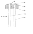
- FIGURE is a side sectional view of an embodiment of the present invention.
- a preferred embodiment of a header 20 includes a ground pin 30 , a central isolated pin 40 , a primary glass insulator 50 , an overlying eyelet 60 , and a bridgewire 70 , with the primary glass insulator 50 being recessed below and substantially covered over by the eyelet 60 . Consequently, the top of the pin 70 is flush with the top surface of the eyelet 60 , and separated therefrom by an annular region that is filled with a secondary glass insulator 80 , or, alternately (not shown), with an ignition pyrotechnic charge.
- the eyelet of the present invention may desirably be fabricated of nickel-plated 1010 carbon steel. Further, the eyelet can be stamped or cold-formed (preferably into a cup-like shape as shown), and then plated with nickel using a standard plating process.
- the eyelet should have a wall thickness that is sufficient to sustain a compression seal and to sustain ballistic firing forces without creating undue stress in the glass. However, it should be thin enough that the header can fit within the allotted space for the initiator assembly, and thin enough to facilitate any desired stamping or cold-forming.
- the hole in eyelet 60 (which includes the upper portion of the isolated pin 40 and the annular region around it) may also simply be punched, preferably after the stamping or cold-forming of the eyelet 60 , and may even be done on the same press.
- the primary glass insulator 50 , pins 30 and 40 , and eyelet 60 are preferably of materials that are selected to result in a compression seal, or less preferably, a matched seal.
- a suitable compression seal would result with a 1010 carbon steel eyelet, a sodasilicate (e.g., TM9) primary glass insulator, and pins of a 52 alloy (or less preferably 42-6 alloy).
- the primary glass insulator can be made of drawn or pressed glass.
- the ground pin 30 may be press fit into a corresponding hole (not shown) in the eyelet 60 , or it can be welded on, or it can be brazed with a solder ring during the sealing process. Both pins are preferably gold-plated, either individually, or as part of the header in “barrel” plating process.
- a secondary glass insulator 80 may made be flush (either by a non-grinding flush-glassing process, or by grinding), or it can have a meniscus.
- the material of a secondary glass insulator 80 is also preferably selected for a compression seal, or less preferably for a matched seal, but in either case, is preferably the same material as the primary glass insulator.
- the secondary glass insulator also may be drawn or pressed, and if pressed, the primary and secondary glass insulators could be made of a single integral pressed piece. If a flush secondary glass insulator is not used, grinding of the top surface of the header may be eliminated since the bridgewire will be suspended above, rather than lying flat against, a glass surface.
- the header can be fixtured upside-down, using a fixture that includes a carbon or other suitable projection (not shown) to displace the primary glass insulator 50 (but not the isolated pin 40 ) away from the top surface of the eyelet 60 during heating and sealing.
- the header might be fixtured right-side-up, using a fixture that includes means positioned below the primary glass insulator 50 to support it at the appropriate height during heating and sealing. While steps can also be taken to ensure that the top surface of the primary glass insulator 50 is flat (as shown in the FIGURE), a meniscus (not shown) on the top surface of the primary glass insulator 50 may also be acceptable.
- an ignition charge is placed in the annular region between the isolated pin 40 and the eyelet 60 rather than a secondary glass insulator 80 , or if a secondary glass insulator 80 is formed with a meniscus and an ignition charge is placed in the sunken region of an insulator 80 below the plane of the top surface of the eyelet 60 , such an ignition charge is preferably dispensed as a droplet.
- a droplet can be dispensed in a liquid or slurry using formulas and techniques known to those of ordinary skill in the art, such as those described in U.S. Pat. No. 5,939,660 to Fogle, Jr., which patent is incorporated herein by reference as if set forth in full.
- Such a droplet can preferably be sprayed or dispensed with volumetric dispensing syringe-type equipment, and if there is no secondary glass insulator, the retention of the droplet in place can be enhanced by the provision of a circumferential notch (not shown) or other irregular surface near the top of isolated pin 40 .
- the header of the present invention can be pressed into a suitable can (not shown) that is loaded with a suitable output pyrotechnic charge (such as one provided using a conventional slurry loading process).
- the header can then be hermetically sealed (for example, with a through-weld) to the can to form an initiator sub-assembly, which can in turn be completed by, for example, a suitable method of insert-molding a nylon body to provide electrical insulation and structural support.
Landscapes
- Engineering & Computer Science (AREA)
- General Engineering & Computer Science (AREA)
- Air Bags (AREA)
Abstract
Disclosed is a pyrotechnic initiator header having an eyelet overlying a recessed primary glass insulator. The recessed region can be filled with a secondary glass insulator and/or a pyrotechnic ignition charge.
Description
- The present invention relates to the field of pyrotechnic initiators, and more particularly to a pyrotechnic initiator having an eyelet that overlies the glass insulator.
- Pyrotechnic initiators have many uses in industrial and consumer applications. One important use is the inflation of airbags in motor vehicles. As airbag production has steadily increased, significant efforts have been made to reduce the cost of reliable airbag initiators. Nevertheless, there remains a substantial need in the automotive airbag industry in particular as well as in other applications, for further reduction in the costs of manufacturing reliable initiators.
- In accordance with the present invention, a header for an initiator is provided that includes an eyelet overlying the glass insulator. A smaller second glass insulator aspect can also be provided, or the bridgewire can be suspended and encapsulated in an ignition droplet.
- The FIGURE is a side sectional view of an embodiment of the present invention.
- In conventional sealed-glass headers, there is a single insulator that is flush with the top surface of a generally cylindrical eyelet. As shown in the FIGURE, however, a preferred embodiment of a
header 20 according to the present invention includes aground pin 30, a central isolatedpin 40, aprimary glass insulator 50, an overlying eyelet 60, and abridgewire 70, with theprimary glass insulator 50 being recessed below and substantially covered over by the eyelet 60. Consequently, the top of thepin 70 is flush with the top surface of the eyelet 60, and separated therefrom by an annular region that is filled with a secondary glass insulator 80, or, alternately (not shown), with an ignition pyrotechnic charge. - Although eyelets in conventional sealed-glass headers are typically machined from stainless steel, the eyelet of the present invention may desirably be fabricated of nickel-plated 1010 carbon steel. Further, the eyelet can be stamped or cold-formed (preferably into a cup-like shape as shown), and then plated with nickel using a standard plating process. The eyelet should have a wall thickness that is sufficient to sustain a compression seal and to sustain ballistic firing forces without creating undue stress in the glass. However, it should be thin enough that the header can fit within the allotted space for the initiator assembly, and thin enough to facilitate any desired stamping or cold-forming. The hole in eyelet 60 (which includes the upper portion of the
isolated pin 40 and the annular region around it) may also simply be punched, preferably after the stamping or cold-forming of the eyelet 60, and may even be done on the same press. - The
primary glass insulator 50,pins ground pin 30 may be press fit into a corresponding hole (not shown) in the eyelet 60, or it can be welded on, or it can be brazed with a solder ring during the sealing process. Both pins are preferably gold-plated, either individually, or as part of the header in “barrel” plating process. - If the annular region between the
isolated pin 40 and the eyelet 60 is filled with a secondary glass insulator 80, it may made be flush (either by a non-grinding flush-glassing process, or by grinding), or it can have a meniscus. The material of a secondary glass insulator 80 is also preferably selected for a compression seal, or less preferably for a matched seal, but in either case, is preferably the same material as the primary glass insulator. The secondary glass insulator also may be drawn or pressed, and if pressed, the primary and secondary glass insulators could be made of a single integral pressed piece. If a flush secondary glass insulator is not used, grinding of the top surface of the header may be eliminated since the bridgewire will be suspended above, rather than lying flat against, a glass surface. - There are a number of ways to seal a header according to the present invention wherein the eyelet overlies a primary glass insulator. For example, the header can be fixtured upside-down, using a fixture that includes a carbon or other suitable projection (not shown) to displace the primary glass insulator 50 (but not the isolated pin 40) away from the top surface of the eyelet 60 during heating and sealing. Alternately, the header might be fixtured right-side-up, using a fixture that includes means positioned below the
primary glass insulator 50 to support it at the appropriate height during heating and sealing. While steps can also be taken to ensure that the top surface of theprimary glass insulator 50 is flat (as shown in the FIGURE), a meniscus (not shown) on the top surface of theprimary glass insulator 50 may also be acceptable. - If an ignition charge is placed in the annular region between the isolated
pin 40 and the eyelet 60 rather than a secondary glass insulator 80, or if a secondary glass insulator 80 is formed with a meniscus and an ignition charge is placed in the sunken region of an insulator 80 below the plane of the top surface of the eyelet 60, such an ignition charge is preferably dispensed as a droplet. Such a droplet can be dispensed in a liquid or slurry using formulas and techniques known to those of ordinary skill in the art, such as those described in U.S. Pat. No. 5,939,660 to Fogle, Jr., which patent is incorporated herein by reference as if set forth in full. Such a droplet can preferably be sprayed or dispensed with volumetric dispensing syringe-type equipment, and if there is no secondary glass insulator, the retention of the droplet in place can be enhanced by the provision of a circumferential notch (not shown) or other irregular surface near the top of isolatedpin 40. - Assignee's co-pending U.S. patent application Ser. No. 09/733,548, filed Dec. 7, 2000, the disclosure of which is incorporated herein by reference as if set forth in full, teaches another recessed header wherein a substantial part of the bridgewire is suspended a distance away from the glass. As with the invention of that application, in the present invention, if a secondary glass insulator is not used, the annular cavity between the isolated pin and the eyelet beneficially helps to maintain the ignition charge in contact with the bridgewire so that it does not move during environmental testing or other physical shocks.
- As evident to one of ordinary skill in the art, the header of the present invention can be pressed into a suitable can (not shown) that is loaded with a suitable output pyrotechnic charge (such as one provided using a conventional slurry loading process). The header can then be hermetically sealed (for example, with a through-weld) to the can to form an initiator sub-assembly, which can in turn be completed by, for example, a suitable method of insert-molding a nylon body to provide electrical insulation and structural support.
- A preferred header with recessed glass insulator, and many of its attendant advantages, has thus been disclosed. It will be apparent, however, that various changes may be made in the form, construction and arrangement of the parts without departing from the spirit and scope of the invention, the form hereinbefore described being merely a preferred or exemplary embodiment thereof. Therefore, the invention is not to be restricted or limited except in accordance with the following claims and their legal equivalents.
Claims (20)
1. A header for use in a pyrotechnic initiator, comprising:
a) an electrically conductive eyelet having an upper eyelet surface and an eyelet bore defining an inner eyelet surface;
b) a primary glass insulator having an outer glass surface and an upper glass surface, and having an insulator bore defining an inner glass surface, wherein said outer glass surface is sealed to said inner eyelet surface, and said upper glass surface is disposed below said upper surface of said eyelet;
c) an electrically conductive center pin having an upper end, said center pin being disposed within said insulator bore and sealed to said inner glass surface; and,
d) a bridgewire attached between said upper eyelet surface and said upper end of said center pin.
2. The header of claim 1 , wherein said upper glass surface is flat.
3. The header of claim 1 , wherein said upper glass surface includes a meniscus.
4. The header of claim 1 , further including an ignition charge droplet that includes a portion that is disposed between said center pin and said inner eyelet surface and extends below the plane of said upper eyelet surface.
5. The header of claim 4 , wherein said droplet further includes a portion that extends above the plane of said upper eyelet surface.
6. The header of claim 4 , wherein said ignition charge droplet extends down to said upper glass surface.
7. The header of claim 6 , wherein said center pin includes a circumferential notch above said upper glass surface and below said upper end of said center pin.
8. The header of claim 1 , further comprising a secondary glass insulator disposed between said center pin and inner eyelet surface, said secondary glass insulator having an upper surface that does not protrude above the plane of said upper eyelet surface.
9. The header of claim 8 , wherein said primary glass insulator and said secondary glass insulator are made from pressed parts.
10. The header of claim 8 , wherein said upper surface of said secondary glass insulator is substantially flat.
11. The header of claim 8 , wherein said upper surface of said secondary glass insulator includes a meniscus.
12. The header of claim 11 , further including an ignition charge droplet that includes a portion that is disposed between said center pin and said inner eyelet surface and extends below the plane of said upper eyelet surface.
13. The header of claim 1 , further including an electrically conductive ground pin that is welded, soldered, or press-fit onto said eyelet.
14. The header of claim 1 , wherein said eyelet is cold-formed.
15. The header of claim 1 , wherein said eyelet is formed by stamping.
16. The header of claim 1 , wherein said eyelet includes at least one punched hole.
17. The header of claim 15 , wherein said eyelet primarily consists of 1010 carbon steel.
18. The header of claim 1 , wherein said eyelet, primary glass insulator, and center pin are selected of materials to result in a compression seal when subjected to a suitable glass sealing process.
19. The header of claim 1 , wherein said header is formed to be attached to a can loaded with an output pyrotechnic charge.
20. The header of claim 19 , wherein said header is further formed to be incorporated into an initiator assembly for use in an automotive airbag inflator.
Priority Applications (3)
| Application Number | Priority Date | Filing Date | Title |
|---|---|---|---|
| US10/124,470 US20030192446A1 (en) | 2002-04-16 | 2002-04-16 | Header with overlying eyelet |
| PCT/IB2003/001329 WO2003087704A1 (en) | 2002-04-16 | 2003-04-10 | Header with overlying eyelet |
| AU2003214533A AU2003214533A1 (en) | 2002-04-16 | 2003-04-10 | Header with overlying eyelet |
Applications Claiming Priority (1)
| Application Number | Priority Date | Filing Date | Title |
|---|---|---|---|
| US10/124,470 US20030192446A1 (en) | 2002-04-16 | 2002-04-16 | Header with overlying eyelet |
Publications (1)
| Publication Number | Publication Date |
|---|---|
| US20030192446A1 true US20030192446A1 (en) | 2003-10-16 |
Family
ID=28790877
Family Applications (1)
| Application Number | Title | Priority Date | Filing Date |
|---|---|---|---|
| US10/124,470 Abandoned US20030192446A1 (en) | 2002-04-16 | 2002-04-16 | Header with overlying eyelet |
Country Status (3)
| Country | Link |
|---|---|
| US (1) | US20030192446A1 (en) |
| AU (1) | AU2003214533A1 (en) |
| WO (1) | WO2003087704A1 (en) |
Cited By (13)
| Publication number | Priority date | Publication date | Assignee | Title |
|---|---|---|---|---|
| US20040216631A1 (en) * | 2003-03-03 | 2004-11-04 | Thomas Fink | Metal fixing material bushing and method for producing a base plate of a metal fixing material bushing |
| US20060208474A1 (en) * | 2003-12-24 | 2006-09-21 | Nippon Kayaku Kabushiki Kaisha | Gas producer |
| US20080250963A1 (en) * | 2003-03-03 | 2008-10-16 | Schott Ag | Metal fixing material bushing and method for producing a base plate of a metal fixing material bushing |
| US20100199872A1 (en) * | 2009-02-12 | 2010-08-12 | Schott Ag | Shaped feed-through element with contact rod soldered in |
| EP2012082A3 (en) * | 2007-07-06 | 2012-11-28 | BC Tech Holding AG | Metal/fixing material cap for ignition devices for airbags or similar personal protection devices, in particular for motor vehicles and ignition device with such a cap |
| US8733250B2 (en) | 2006-01-27 | 2014-05-27 | Schott Ag | Metal-sealing material-feedthrough and utilization of the metal-sealing material feedthrough with an airbag, a belt tensioning device, and an ignition device |
| DE102014219125A1 (en) | 2014-09-23 | 2016-03-24 | Schott Ag | Feedthrough element with directly connected ground pin, process for its preparation and its use |
| DE102014219124A1 (en) | 2014-09-23 | 2016-03-24 | Schott Ag | Feedthrough element with ground spinning in contact sleeve, process for its preparation and its use |
| DE102014219127A1 (en) | 2014-09-23 | 2016-03-24 | Schott Ag | Feedthrough element with welded ground pin, method for its production and its use |
| US9423218B2 (en) | 2010-09-17 | 2016-08-23 | Schott Ag | Method for producing a ring-shaped or plate-like element |
| EP3104114A1 (en) * | 2006-01-27 | 2016-12-14 | Schott Ag | Metal fusing material and method for manufacturing a carrier for a duct with metal fusing material |
| US10684102B2 (en) | 2010-09-17 | 2020-06-16 | Schott Ag | Method for producing a ring-shaped or plate-like element |
| USD1030941S1 (en) * | 2020-08-05 | 2024-06-11 | Liaoning Qingyang Explosive Materials Co., Ltd | Detonator cover |
Citations (8)
| Publication number | Priority date | Publication date | Assignee | Title |
|---|---|---|---|---|
| US5821446A (en) * | 1997-05-27 | 1998-10-13 | Trw Inc. | Inflator for an inflatable vehicle occupant protection device |
| US5939660A (en) * | 1997-03-12 | 1999-08-17 | Trw Inc. | Inflator for an inflatable vehicle occupant protection device |
| US6446557B1 (en) * | 1997-08-01 | 2002-09-10 | Nico-Pyrotechnik Hanns-Juergen Diedrichs Gmbh & Co. Kg | Ignition unit for a passenger protection device of a motor vehicle |
| US6557474B1 (en) * | 2000-08-30 | 2003-05-06 | Glasseal Products | Initiator header subassembly for inflation devices |
| US6578487B2 (en) * | 2000-12-08 | 2003-06-17 | Special Devices, Inc. | Pyrotechnic initiator with a narrowed sleeve retaining a pyrotechnic charge and methods of making same |
| US6612241B2 (en) * | 2000-12-07 | 2003-09-02 | Special Devices, Inc. | Pyrotechnic initiator with center pin having a circumferential notch retention feature |
| US20030172831A1 (en) * | 2000-08-09 | 2003-09-18 | Shingo Oda | Electric initiator and initiator assembly using it |
| US6640718B2 (en) * | 2000-05-30 | 2003-11-04 | Livbag S.N.C. Centre De Recherches Du Bouchet | Thin-film bridge electropyrotechnic initiator with a very low operating energy |
Family Cites Families (7)
| Publication number | Priority date | Publication date | Assignee | Title |
|---|---|---|---|---|
| NL181741B (en) * | 1953-07-16 | Colgate Palmolive Co | LIQUID CLEANER FOR HARD SURFACES. | |
| FR1204477A (en) * | 1957-04-04 | 1960-01-26 | Wasagchemie Ag | Electric rocket firing device |
| US3257947A (en) * | 1964-12-17 | 1966-06-28 | Ernest E Mallory | Shock focusing explosive initiator |
| FR1590068A (en) * | 1966-06-30 | 1970-04-13 | ||
| US3557699A (en) * | 1968-06-26 | 1971-01-26 | Olin Mathieson | Electroexplosive primer ignition assembly |
| DE4229624C2 (en) * | 1991-09-05 | 2000-12-07 | Trw Inc | Inflator for a vehicle occupant restraint |
| DE19647397C2 (en) | 1996-11-15 | 1999-04-15 | Siemens Ag | Underfloor container |
-
2002
- 2002-04-16 US US10/124,470 patent/US20030192446A1/en not_active Abandoned
-
2003
- 2003-04-10 WO PCT/IB2003/001329 patent/WO2003087704A1/en not_active Ceased
- 2003-04-10 AU AU2003214533A patent/AU2003214533A1/en not_active Abandoned
Patent Citations (8)
| Publication number | Priority date | Publication date | Assignee | Title |
|---|---|---|---|---|
| US5939660A (en) * | 1997-03-12 | 1999-08-17 | Trw Inc. | Inflator for an inflatable vehicle occupant protection device |
| US5821446A (en) * | 1997-05-27 | 1998-10-13 | Trw Inc. | Inflator for an inflatable vehicle occupant protection device |
| US6446557B1 (en) * | 1997-08-01 | 2002-09-10 | Nico-Pyrotechnik Hanns-Juergen Diedrichs Gmbh & Co. Kg | Ignition unit for a passenger protection device of a motor vehicle |
| US6640718B2 (en) * | 2000-05-30 | 2003-11-04 | Livbag S.N.C. Centre De Recherches Du Bouchet | Thin-film bridge electropyrotechnic initiator with a very low operating energy |
| US20030172831A1 (en) * | 2000-08-09 | 2003-09-18 | Shingo Oda | Electric initiator and initiator assembly using it |
| US6557474B1 (en) * | 2000-08-30 | 2003-05-06 | Glasseal Products | Initiator header subassembly for inflation devices |
| US6612241B2 (en) * | 2000-12-07 | 2003-09-02 | Special Devices, Inc. | Pyrotechnic initiator with center pin having a circumferential notch retention feature |
| US6578487B2 (en) * | 2000-12-08 | 2003-06-17 | Special Devices, Inc. | Pyrotechnic initiator with a narrowed sleeve retaining a pyrotechnic charge and methods of making same |
Cited By (22)
| Publication number | Priority date | Publication date | Assignee | Title |
|---|---|---|---|---|
| US20040216631A1 (en) * | 2003-03-03 | 2004-11-04 | Thomas Fink | Metal fixing material bushing and method for producing a base plate of a metal fixing material bushing |
| US20060222881A1 (en) * | 2003-03-03 | 2006-10-05 | Schott Ag | Metal fixing material bushing and method for producing a base plate of a metal fixing material bushing |
| US20080250963A1 (en) * | 2003-03-03 | 2008-10-16 | Schott Ag | Metal fixing material bushing and method for producing a base plate of a metal fixing material bushing |
| US20100229616A1 (en) * | 2003-03-03 | 2010-09-16 | Schott Ag | Metal fixing material bushing and method for producing a base plate of a metal fixing material bushing |
| US8276514B2 (en) | 2003-03-03 | 2012-10-02 | Schott Ag | Metal fixing material bushing and method for producing a base plate of a metal fixing material bushing |
| US8327765B2 (en) | 2003-03-03 | 2012-12-11 | Schott Ag | Metal fixing material bushing and method for producing a base plate of a metal fixing material bushing |
| US20060208474A1 (en) * | 2003-12-24 | 2006-09-21 | Nippon Kayaku Kabushiki Kaisha | Gas producer |
| EP3104114A1 (en) * | 2006-01-27 | 2016-12-14 | Schott Ag | Metal fusing material and method for manufacturing a carrier for a duct with metal fusing material |
| US8733250B2 (en) | 2006-01-27 | 2014-05-27 | Schott Ag | Metal-sealing material-feedthrough and utilization of the metal-sealing material feedthrough with an airbag, a belt tensioning device, and an ignition device |
| EP2012082A3 (en) * | 2007-07-06 | 2012-11-28 | BC Tech Holding AG | Metal/fixing material cap for ignition devices for airbags or similar personal protection devices, in particular for motor vehicles and ignition device with such a cap |
| US8661977B2 (en) | 2009-02-12 | 2014-03-04 | Schott Ag | Shaped feed-through element with contact rod soldered in |
| US8397638B2 (en) | 2009-02-12 | 2013-03-19 | Schott Ag | Shaped feed-through element with contact rod soldered in |
| US20100199872A1 (en) * | 2009-02-12 | 2010-08-12 | Schott Ag | Shaped feed-through element with contact rod soldered in |
| US9423218B2 (en) | 2010-09-17 | 2016-08-23 | Schott Ag | Method for producing a ring-shaped or plate-like element |
| CN106111878A (en) * | 2010-09-17 | 2016-11-16 | 肖特股份有限公司 | For the method manufacturing ring-type element or plate element |
| US9651345B2 (en) | 2010-09-17 | 2017-05-16 | Schott Ag | Method for producing a ring-shaped or plate-like element |
| US10684102B2 (en) | 2010-09-17 | 2020-06-16 | Schott Ag | Method for producing a ring-shaped or plate-like element |
| DE102014219125A1 (en) | 2014-09-23 | 2016-03-24 | Schott Ag | Feedthrough element with directly connected ground pin, process for its preparation and its use |
| DE102014219124A1 (en) | 2014-09-23 | 2016-03-24 | Schott Ag | Feedthrough element with ground spinning in contact sleeve, process for its preparation and its use |
| DE102014219127A1 (en) | 2014-09-23 | 2016-03-24 | Schott Ag | Feedthrough element with welded ground pin, method for its production and its use |
| DE102014219124B4 (en) * | 2014-09-23 | 2021-02-18 | Schott Ag | Feed-through element with ground pin in contact sleeve, method for its production and its use |
| USD1030941S1 (en) * | 2020-08-05 | 2024-06-11 | Liaoning Qingyang Explosive Materials Co., Ltd | Detonator cover |
Also Published As
| Publication number | Publication date |
|---|---|
| AU2003214533A1 (en) | 2003-10-27 |
| WO2003087704A1 (en) | 2003-10-23 |
Similar Documents
| Publication | Publication Date | Title |
|---|---|---|
| US20020069781A1 (en) | Recessed glass header for pyrotechnic initiators | |
| US20030192446A1 (en) | Header with overlying eyelet | |
| US11150060B2 (en) | Ring-shaped or plate-like element and method for producing same | |
| EP1379408B1 (en) | Unitary header/base/shorting bar holder for a micro gas generator, and micro gas generator using it | |
| US6578487B2 (en) | Pyrotechnic initiator with a narrowed sleeve retaining a pyrotechnic charge and methods of making same | |
| US5596163A (en) | Gas generator igniting capsule | |
| US9651345B2 (en) | Method for producing a ring-shaped or plate-like element | |
| US7124688B2 (en) | Overmolded body for pyrotechnic initiator and method of molding same | |
| US20050126415A1 (en) | Initiator | |
| EP0266541B1 (en) | Explosion-proof arrangement for a non-aqueous electrochemical cell, and method for the production thereof | |
| MXPA06013611A (en) | Metal fixing material bushing and method for producing a base plate of a metal fixing material bushing . | |
| JP2005531744A (en) | Initiator comprising an inner sleeve for holding a pyrotechnic drug and method for manufacturing the same | |
| US20200109927A1 (en) | Vibration resistant initiator assembly having exploding foil initiator | |
| US11578954B2 (en) | Igniter for a gas generator and method for producing an igniter | |
| US10684102B2 (en) | Method for producing a ring-shaped or plate-like element | |
| EP1402226B1 (en) | Pyrotechnic initiator with on-board control circuitry | |
| US20040000249A1 (en) | Initiator with a bridgewire configured in an enhanced heat-sinking relationship | |
| US6907827B2 (en) | Pyrotechnic initiator having output can with encapsulation material retention feature | |
| US20030221578A1 (en) | Detonator with onboard electronics mechanically connected to ignition element | |
| US20030221575A1 (en) | Detonator utilizing features of automotive airbag initiators | |
| US20030221577A1 (en) | Standalone ignition subassembly for detonators | |
| US20030221576A1 (en) | Detonator with an ignition element having a transistor-type sealed feedthrough | |
| KR20010031971A (en) | Boundary light cartridge and production method therefor | |
| WO2006021491A1 (en) | An initiator body with a molded gasket, an initiator and a generator provided therewith, and a method of manufacture |
Legal Events
| Date | Code | Title | Description |
|---|---|---|---|
| AS | Assignment |
Owner name: SPECIAL DEVICES, INC., CALIFORNIA Free format text: ASSIGNMENT OF ASSIGNORS INTEREST;ASSIGNORS:BERG, PAUL;AVETISIAN, VAHAN;RENZ, ROBERT;AND OTHERS;REEL/FRAME:014464/0748;SIGNING DATES FROM 20030218 TO 20030311 |
|
| STCB | Information on status: application discontinuation |
Free format text: ABANDONED -- FAILURE TO RESPOND TO AN OFFICE ACTION |