JP4516552B2 - Valve control mechanism - Google Patents
Valve control mechanism Download PDFInfo
- Publication number
- JP4516552B2 JP4516552B2 JP2006249486A JP2006249486A JP4516552B2 JP 4516552 B2 JP4516552 B2 JP 4516552B2 JP 2006249486 A JP2006249486 A JP 2006249486A JP 2006249486 A JP2006249486 A JP 2006249486A JP 4516552 B2 JP4516552 B2 JP 4516552B2
- Authority
- JP
- Japan
- Prior art keywords
- swing arm
- valve
- pin
- drive
- cam
- Prior art date
- Legal status (The legal status is an assumption and is not a legal conclusion. Google has not performed a legal analysis and makes no representation as to the accuracy of the status listed.)
- Expired - Fee Related
Links
Images


Classifications
-
- F—MECHANICAL ENGINEERING; LIGHTING; HEATING; WEAPONS; BLASTING
- F01—MACHINES OR ENGINES IN GENERAL; ENGINE PLANTS IN GENERAL; STEAM ENGINES
- F01L—CYCLICALLY OPERATING VALVES FOR MACHINES OR ENGINES
- F01L1/00—Valve-gear or valve arrangements, e.g. lift-valve gear
- F01L1/26—Valve-gear or valve arrangements, e.g. lift-valve gear characterised by the provision of two or more valves operated simultaneously by same transmitting-gear; peculiar to machines or engines with more than two lift-valves per cylinder
- F01L1/267—Valve-gear or valve arrangements, e.g. lift-valve gear characterised by the provision of two or more valves operated simultaneously by same transmitting-gear; peculiar to machines or engines with more than two lift-valves per cylinder with means for varying the timing or the lift of the valves
-
- F—MECHANICAL ENGINEERING; LIGHTING; HEATING; WEAPONS; BLASTING
- F01—MACHINES OR ENGINES IN GENERAL; ENGINE PLANTS IN GENERAL; STEAM ENGINES
- F01L—CYCLICALLY OPERATING VALVES FOR MACHINES OR ENGINES
- F01L1/00—Valve-gear or valve arrangements, e.g. lift-valve gear
- F01L1/02—Valve drive
- F01L1/04—Valve drive by means of cams, camshafts, cam discs, eccentrics or the like
- F01L1/08—Shape of cams
-
- F—MECHANICAL ENGINEERING; LIGHTING; HEATING; WEAPONS; BLASTING
- F01—MACHINES OR ENGINES IN GENERAL; ENGINE PLANTS IN GENERAL; STEAM ENGINES
- F01L—CYCLICALLY OPERATING VALVES FOR MACHINES OR ENGINES
- F01L13/00—Modifications of valve-gear to facilitate reversing, braking, starting, changing compression ratio, or other specific operations
- F01L13/0015—Modifications of valve-gear to facilitate reversing, braking, starting, changing compression ratio, or other specific operations for optimising engine performances by modifying valve lift according to various working parameters, e.g. rotational speed, load, torque
- F01L13/0036—Modifications of valve-gear to facilitate reversing, braking, starting, changing compression ratio, or other specific operations for optimising engine performances by modifying valve lift according to various working parameters, e.g. rotational speed, load, torque the valves being driven by two or more cams with different shape, size or timing or a single cam profiled in axial and radial direction
-
- F—MECHANICAL ENGINEERING; LIGHTING; HEATING; WEAPONS; BLASTING
- F01—MACHINES OR ENGINES IN GENERAL; ENGINE PLANTS IN GENERAL; STEAM ENGINES
- F01L—CYCLICALLY OPERATING VALVES FOR MACHINES OR ENGINES
- F01L1/00—Valve-gear or valve arrangements, e.g. lift-valve gear
- F01L1/34—Valve-gear or valve arrangements, e.g. lift-valve gear characterised by the provision of means for changing the timing of the valves without changing the duration of opening and without affecting the magnitude of the valve lift
- F01L1/344—Valve-gear or valve arrangements, e.g. lift-valve gear characterised by the provision of means for changing the timing of the valves without changing the duration of opening and without affecting the magnitude of the valve lift changing the angular relationship between crankshaft and camshaft, e.g. using helicoidal gear
- F01L1/3442—Valve-gear or valve arrangements, e.g. lift-valve gear characterised by the provision of means for changing the timing of the valves without changing the duration of opening and without affecting the magnitude of the valve lift changing the angular relationship between crankshaft and camshaft, e.g. using helicoidal gear using hydraulic chambers with variable volume to transmit the rotating force
- F01L2001/34423—Details relating to the hydraulic feeding circuit
- F01L2001/34426—Oil control valves
- F01L2001/3443—Solenoid driven oil control valves
Landscapes
- Engineering & Computer Science (AREA)
- Mechanical Engineering (AREA)
- General Engineering & Computer Science (AREA)
- Valve Device For Special Equipments (AREA)
Description
本発明は一種の弁制御機構、特に一種の油回路と構造設計の簡素化により、弁に3種類以上の開閉パターンを提供する、一種の弁制御機構に関わるものである。 The present invention relates to a kind of valve control mechanism, in particular, a kind of valve control mechanism that provides a valve with three or more kinds of opening / closing patterns by simplification of a kind of oil circuit and structure.
近年、石油価格の暴騰により、エンジンの燃費性能が非常に重視されている。研究資料によると、弁可変制御機構技術の重要性は非常に高い。その技術は気筒休止(cylinder deactivation)、エンジンの小型化(downsize)など多種の技術基礎である。 In recent years, due to the surge in oil prices, the fuel efficiency of engines has become very important. According to research data, the importance of valve variable control mechanism technology is very high. The technology is based on various technologies such as cylinder deactivation and engine downsizing.
弁揚程の変更は、以下の方法を通じて、燃費低減の効果を実現できる、
1.高または低弁揚程、エンジンの回転速度の高低に従い、最適化に設計された二つの吸気弁揚程は、エンジンが高速回転のとき、高揚程に切り換えて吸気効率を向上し馬力を増大させ、省エネ効果を実現する。そして、中低回転速度のとき、低揚程に切り換えて、吸気の流速を増加し、カム軸のトルクを下げて、安定したアイドル運転燃焼により、省エネ効果を実現する。この類の代表的な技術は本田社のシビックとアコードなどの車種に使用されている。このほか、BMW社のValve Tronicシリーズは、弁揚程連続可変技術を駆使し、エンジン回転速度の最適化を実現する、
2.二つの吸気弁に高低揚程を行う。その目的は、低い回転速度のとき、一つの弁のみが吸気を担ぐ、気筒内部に強いスワール(swirl)を形成し、燃焼の改善により、省エネ効果を実現する。一方、高速回転のとき、二つの吸気弁とも高揚程状態に切り換える。代表的な車種は本田社のCB400F。しかし、中低速回転のとき、燃料が弁のダイアフラムに堆積し、空気燃料比率の不正確とカーボン堆積の欠点があるため、一つの吸気弁を高揚程に設定し、もう一つの吸気弁を低揚程に設定することで防止する、
3.すべての弁揚程を締め切る。容積が大きいエンジンまたは混合動力エンジンが低回転のとき、一部の気筒の弁揚程を締め切ることにより、気筒休止ときのポンピングロス(pumping loss)の軽減を図る。この種の技術の代表的な技術は本田社のインサイト。
The change in the valve head can achieve the effect of reducing fuel consumption through the following methods.
1. Two intake valve lifts designed for optimization according to high or low valve lift and engine speed, switch to high lift when the engine is rotating at high speed to improve intake efficiency and increase horsepower, saving energy Realize the effect. At medium and low rotational speeds, switching to a low head, increasing the flow rate of intake air, lowering the torque of the camshaft, and realizing an energy saving effect by stable idle operation combustion. Representative technologies of this kind are used in Honda's Civic and Accord models. In addition, BMW's Valve Tronic series uses a continuously variable valve lift technology to optimize engine speed.
2. High and low heads for the two intake valves. The purpose is to form a strong swirl inside the cylinder, in which only one valve carries the intake air at a low rotational speed, and realizes an energy saving effect by improving combustion. On the other hand, at the time of high speed rotation, both intake valves are switched to the high head state. A typical model is Honda's CB400F. However, during medium and low speed rotation, fuel accumulates on the valve diaphragm, and there is an inaccuracy of the air fuel ratio and the disadvantages of carbon accumulation, so one intake valve is set at a high head and the other intake valve is lowered. Prevent by setting the head,
3. Close all valve heads. When the engine having a large volume or the mixed power engine is running at a low speed, the pumping loss during cylinder deactivation is reduced by closing the valve lift of some cylinders. Representative of this type of technology is Honda's insight.
公知技術は前記の目的を達成するため、さまざまな弁揚程の制御技術が開発されている。特許文献1において、ピン機構の切り替えによる弁揚程の制御技術が開示されている。この種の技術における弁揚程の種類は片方の弁を閉めるか、または一方を高揚程に、もう一方を低揚程に制御する。さらに、特許文献2において、一種のカムと揺腕をそれぞれ3つ設けて、高−高の組み合わせと中−低の組み合わせ、2種類の弁揚程制御を行う。このほか、特許文献3において、一種のカムと揺腕をそれぞれ3つ設けて、二つの弁を制御し、高−高の組み合わせ、または高−低の組み合わせ、もしくは中−低の組み合わせ、3種類の弁揚程制御を行う。
In the known technique, various control techniques for the valve head have been developed in order to achieve the above-mentioned object. In
前記した公知技術は、多種の組み合わせの揚程を形成できる。しかしながら、一つのエンジンにおいて、高速回転馬力、中速回転スワール、気筒休止並びにエンジンストップなどの場面に合わせた弁揚程制御ができない。よって、一種の弁制御機構により、公知技術の不足点を補完する必要がある。 The known techniques described above can form a variety of combinations of heads. However, in one engine, it is impossible to control the valve head according to scenes such as high-speed rotation horsepower, medium-speed rotation swirl, cylinder deactivation, and engine stop. Therefore, it is necessary to supplement the deficiencies of the known technology with a kind of valve control mechanism.
気筒に備える二つの吸気弁を高−高揚程、高−低揚程、および弁休止の組み合わせにより、一つのエンジンにおいて、高速回転のとき大きい馬力、中低速回転のとき、スワールおよび気筒休止合制御を図る、一種の弁制御機構を提供することを本発明の主な目的である。 By combining the two intake valves in the cylinder with a combination of high-high lift, high-low lift, and valve deactivation, one engine can perform large horsepower at high speed rotation, swirl and cylinder deactivation control at medium / low speed rotation. It is a main object of the present invention to provide a kind of valve control mechanism.
切り替えピンと油回路は3本以下、油回路を制御する電磁弁は2個以下を設け、気筒に備える二つの吸気弁に高−高揚程、高−低揚程およびバルブ休止を制御する、一種の弁制御機構を提供することを本発明の次の目的である。 A type of valve that has three or fewer switching pins and oil circuits, and two or less solenoid valves that control the oil circuit, and controls the high-high head, high-low head, and valve rest on the two intake valves provided in the cylinder It is a next object of the present invention to provide a control mechanism.
切り替えピンと油回路を制御することにより、吸気弁揚程制御機構の簡素化およびコスト軽減を図る、一種の弁制御機構を提供することを本発明のもう一つの目的である。 It is another object of the present invention to provide a kind of valve control mechanism that simplifies the intake valve lift control mechanism and reduces the cost by controlling the switching pin and the oil circuit.
前記の目的を達成するため、本発明の弁制御機構は、弁の制御により、高−高揚程、高−低揚程、およびバルブ休止など3種類以上の開閉パターンを形成できる。該弁制御機構はさらに、3本以下の油回路と2個以下の電磁弁を設けて、3種類の揚程変化を実現する。 In order to achieve the above object, the valve control mechanism of the present invention can form three or more open / close patterns such as a high-high head, a high-low head, and a valve pause by controlling the valve. The valve control mechanism is further provided with three or less oil circuits and two or less solenoid valves to realize three types of lift changes.
本発明の弁制御機構は、第1弁揺腕と第2弁揺腕をそれぞれ第1弁と第2弁に連結する。第1駆動揺腕を該第1弁揺腕の一端に設け、該第1駆動揺腕は第1カムの駆動により、
運動を開始する。第2駆動揺腕を該第2弁揺腕の一端に設け、該第2駆動揺腕は第2カムの駆動により運動を開始する。第1連結ユニットは選択により、該第1駆動揺腕と該第1弁揺腕を連結するか、または該第1弁揺腕と第2弁揺腕を連結できる。第2連結ユニットは選択により、該第2駆動揺腕と該第2弁揺腕とを連結させるか分離させる。
The valve control mechanism of the present invention connects the first valve swing arm and the second valve swing arm to the first valve and the second valve, respectively. A first drive swing arm is provided at one end of the first valve swing arm, and the first drive swing arm is driven by the first cam.
Start exercise. A second drive swing arm is provided at one end of the second valve swing arm, and the second drive swing arm starts to move when the second cam is driven. The first connecting unit can connect the first driving rocker arm and the first valve rocking arm, or connect the first valve rocking arm and the second valve rocking arm, depending on selection. The second connecting unit connects or separates the second drive swing arm and the second valve swing arm according to selection.
該第1連結ユニットまたは該第2連結ユニットは、弾性体と油圧駆動素子より構成する切り替えピン、該切り替えピンは開放ピンまたは閉鎖ピンのいずれを選択できることが好ましい。このほか、該第1連結ユニットまたは該第2連結ユニットは二方向油圧駆動ピンであっても良い。 The first connection unit or the second connection unit is preferably a switching pin configured by an elastic body and a hydraulic drive element, and the switching pin can preferably select either an open pin or a closed pin. In addition, the first connection unit or the second connection unit may be a two-way hydraulic drive pin.
本発明の弁制御機構は、第1弁揺腕と第2弁揺腕をそれぞれ第1弁と第2弁に連結し、
該第1弁揺腕は、第1カムの駆動により運動を開始する。駆動揺腕を該第1弁揺腕と第2弁揺腕の間に設け、該駆動揺腕は第2カムの駆動により運動を開始する。第1連結ユニットを設け、該第1連結ユニットにより該駆動揺腕と該第1弁揺腕との連結、または該駆動揺腕と該第1弁揺腕との分離を選択できる。第2連結ユニットを設け、該第2連結ユニットにより該駆動揺腕と該第2弁揺腕との連結または分離を選択できる。
The valve control mechanism of the present invention connects the first valve swing arm and the second valve swing arm to the first valve and the second valve, respectively.
The first valve swing arm starts to move by driving the first cam. A drive swing arm is provided between the first valve swing arm and the second valve swing arm, and the drive swing arm starts to move by driving the second cam. A first connection unit is provided, and the connection between the drive swing arm and the first valve swing arm or the separation between the drive swing arm and the first valve swing arm can be selected by the first connection unit. A second connection unit is provided, and connection or separation between the drive swing arm and the second valve swing arm can be selected by the second connection unit.
該第1弁揺腕と該第1カムとの間に、動力伝達ユニットを該第1弁揺腕に設け、該第1弁揺腕は該第1カムの伝達動力を受け入れることが好ましい。該動力伝達ユニットはさらに円筒体を設け、第1貫通孔と限流孔を設けて、該第1貫通孔と該限流孔との間に収容空間を設ける。ノックピンを該第1貫通孔に設け、該ノックピンの一端と該第1カムに合わせて設ける。該ノックピンは該第1貫通孔内部にて滑り移動を可能とする。油回路制御ユニットを設け、該限流孔に連結する該油回路制御ユニットは油体を該収容空間に流入させるか、または該収容空間の油体の放出を選択できる。 It is preferable that a power transmission unit is provided in the first valve swing arm between the first valve swing arm and the first cam, and the first valve swing arm receives the transmission power of the first cam. The power transmission unit is further provided with a cylindrical body, a first through hole and a current limiting hole are provided, and an accommodation space is provided between the first through hole and the current limiting hole. A knock pin is provided in the first through hole, and is provided in accordance with one end of the knock pin and the first cam. The knock pin allows sliding movement within the first through hole. The oil circuit control unit which is provided with an oil circuit control unit and is connected to the current limiting hole can select an oil body to flow into the accommodation space or release of the oil body in the accommodation space.
該第1弁揺腕と該第1カムとの間に、動力伝達ユニットを設け、該第1弁揺腕は該第1カムの伝達動力を受け入れることが好ましい。該動力伝達ユニットはさらに、台座を設け、第1収容空間、第2収容空間、および液体を提供するための液体圧力管線を設ける。該1ノックピンを該第1収容空間内部に設け、該1ノックピンの底部に、第1弾性体を設ける。該第1ノックピンの一端に凹み部を設ける。第2ノックピンを該第2収容空間内部に設け、その一端は該油圧回路に連結し、該第2ノックピンはさらに、第2弾性体に連結する。該第2ノックピンの一端は該液体と該第2弾性体の働きにより、該凹み部に締結するか、または離れるかを選択できる。 It is preferable that a power transmission unit is provided between the first valve swing arm and the first cam, and the first valve swing arm receives the transmission power of the first cam. The power transmission unit further includes a pedestal, and a first storage space, a second storage space, and a liquid pressure line for providing a liquid. The one knock pin is provided inside the first accommodation space, and a first elastic body is provided at the bottom of the one knock pin. A recess is provided at one end of the first knock pin. A second knock pin is provided in the second housing space, one end of which is connected to the hydraulic circuit, and the second knock pin is further connected to the second elastic body. One end of the second knock pin can be selected to be fastened or separated from the recess by the action of the liquid and the second elastic body.
請求項1の発明は、第1弁揺腕、第2弁揺腕、第1駆動揺腕、第2駆動揺腕、第1連結ユニット、第2連結ユニットを含み、
該第1弁揺腕は第1弁に、該第2弁揺腕は第2弁にそれぞれ連結し、
該第1駆動揺腕は該第1弁揺腕の一端に設け、該第1駆動揺腕は、第1カムの駆動により運動を開始し、
該第2駆動揺腕は該第2弁揺腕の一端に設け、該第2駆動揺腕は、第2カムの駆動により運動を開始し、
該第1連結ユニットは、該第1駆動揺腕と該第1弁揺腕を連結するか、または該第1弁揺腕を該第2弁揺腕と連結するかを選択でき、
第2連結ユニットは、該第2駆動揺腕と該第2弁揺腕を連結するか分離するかを選択できることを特徴とする弁制御機構としている。
請求項2の発明は、該第1連結ユニットは弾性体と油圧駆動素子より構成する切り替えピン、または双方向油圧駆動ピンのいずれを選択でき、該切り替えピンは閉鎖ピンと開放ピンのいずれが選択可能であることを特徴とする請求項1記載のバルブ制御機構としている。
請求項3の発明は、該第2連結ユニットは弾性体と油圧駆動素子より構成する切り替えピン、または双方向油圧駆動ピンのいずれを選択でき、該切り替えピンは閉鎖ピンと開放ピンのいずれが選択可能であることを特徴とする請求項1記載のバルブ制御機構としている。
請求項4の発明は、第1弁に接続されて第1カムにより駆動される第1弁揺腕と、第2弁に接続された第2弁揺腕と、
該第1弁揺腕と該第2弁揺腕の間に設置されて、第2カムの駆動により駆動される駆動揺腕と、
選択的に該駆動揺腕を該第1弁揺腕と連結或いは分離させる第1連結ユニットと、
選択的に該駆動揺腕を該第2弁揺腕と連結或いは分離させる第2連結ユニットと、
を包含したバルブ制御機構において、
該第1弁揺腕に動力伝達ユニットを設け、該第1弁揺腕は該第1カムの伝動力を受け入れ、該動力伝達ユニットはさらに円筒体を有し、第1貫通孔と限流孔を設け、該第1貫通孔と限流孔との間に収容空間を設け、
ノックピンは該第1貫通孔内部に設け、該ノックピンの一端は該第1カムに合わせて設け、該ノックピンは第1貫通孔内部に移動でき、
油路制御ユニットは該限流孔に連結し、該油路制御ユニットは油体を該収容空間に流入と放出を選択操作できることを特徴とする弁制御機構としている。
請求項5の発明は、第1弁に接続されて第1カムにより駆動される第1弁揺腕と、第2弁に接続された第2弁揺腕と、
該第1弁揺腕と該第2弁揺腕の間に設置されて、第2カムの駆動により駆動される駆動揺腕と、
選択的に該駆動揺腕を該第1弁揺腕と連結或いは分離させる第1連結ユニットと、
選択的に該駆動揺腕を該第2弁揺腕と連結或いは分離させる第2連結ユニットと、
を包含したバルブ制御機構において、
該第1弁揺腕に動力伝達ユニットを設けて、第1弁揺腕より該第1カムの伝動力を受け入れ、該動力伝達ユニットはさらに、台座、第1ノックピン及び第2ノックピンを含み、該台座は第1収容空間、第2収容空間および液体を提供するための油圧回路を備え、
該第1ノックピンは該第1収容空間に内設し、該第1ノックピンの底部はさらに第1弾性体を設け、該第1ノックピンの一端に凹み部を設け、
該第2ノックピンは該第2収容空間に内設し、その一部は該油圧回路に連結し、該第2ノックピンの底部はさらに該第2弾性体に連結し、該第2ノックピンの一端は該液体と該第2弾性体の働きにより、該凹み部に締結するか、または引き離すことを選択できることを特徴とする弁制御機構としている。
The invention of
The first valve swing arm is connected to the first valve, and the second valve swing arm is connected to the second valve.
The first drive swing arm is provided at one end of the first valve swing arm, and the first drive swing arm starts to move by driving the first cam;
The second drive swing arm is provided at one end of the second valve swing arm, and the second drive swing arm starts to move by driving the second cam,
The first connection unit can select whether to connect the first drive swing arm and the first valve swing arm or to connect the first valve swing arm to the second valve swing arm;
The second connecting unit is a valve control mechanism that can select whether to connect or separate the second drive swing arm and the second valve swing arm.
According to the invention of
In the invention according to
The invention of claim 4 includes a first valve swing arm connected to the first valve and driven by the first cam, a second valve swing arm connected to the second valve,
A drive swing arm installed between the first valve swing arm and the second valve swing arm and driven by driving of the second cam;
A first connection unit that selectively connects or separates the drive swing arm with the first valve swing arm;
A second connection unit that selectively connects or separates the drive swing arm with the second valve swing arm;
In the valve control mechanism including
The first valve swing arm is provided with a power transmission unit, the first valve swing arm receives the power transmitted from the first cam, the power transmission unit further includes a cylindrical body, a first through hole, and a current limiting hole. Providing an accommodation space between the first through hole and the current limiting hole,
A knock pin is provided in the first through hole, one end of the knock pin is provided in accordance with the first cam, the knock pin is movable in the first through hole,
The oil passage control unit is connected to the current limiting hole, and the oil passage control unit is configured as a valve control mechanism capable of selectively operating the inflow and the discharge of the oil body into the accommodation space.
The invention of
A drive swing arm installed between the first valve swing arm and the second valve swing arm and driven by driving of the second cam;
A first connection unit that selectively connects or separates the drive swing arm with the first valve swing arm;
A second connection unit that selectively connects or separates the drive swing arm with the second valve swing arm;
In the valve control mechanism including
A power transmission unit is provided on the first valve swing arm to receive the power transmitted from the first cam from the first valve swing arm, and the power transmission unit further includes a base, a first knock pin, and a second knock pin, The pedestal includes a first accommodating space, a second accommodating space, and a hydraulic circuit for providing liquid,
The first knock pin is provided in the first accommodation space, the bottom of the first knock pin is further provided with a first elastic body, and a recess is provided at one end of the first knock pin;
The second knock pin is provided in the second receiving space, a part of the second knock pin is connected to the hydraulic circuit, a bottom portion of the second knock pin is further connected to the second elastic body, and one end of the second knock pin is The valve control mechanism is characterized in that it can be selected to be fastened to or pulled away from the recess by the action of the liquid and the second elastic body.
本発明は弁制御機構、気筒に備える二つの吸気弁を高−高揚程、高−低揚程、および弁休止の組み合わせにより、一つのエンジンにおいて、高速回転のとき大きい馬力、中低速回転のとき、スワールおよび気筒休止合制御を図る。切り替えピンと油回路は3本以下、油回路を制御する電磁弁は2個以下を設け、気筒に備える二つの吸気弁に高−高揚程、高−低揚程およびバルブ休止を制御する。切り替えピンと油回路を制御することにより、吸気弁揚程制御機構の簡素化およびコスト軽減を図る。 The present invention is a combination of a high-high head, a high-low head, and a valve pause in which two intake valves provided in a cylinder are combined with a valve control mechanism and a single engine. A swirl and cylinder deactivation control is aimed at. Three or less switching pins and oil circuits are provided, and two or less solenoid valves for controlling the oil circuit are provided, and two intake valves provided in the cylinder are controlled for high-high head, high-low head, and valve pause. By controlling the switching pin and the oil circuit, the intake valve lift control mechanism is simplified and the cost is reduced.
本発明の弁制御機構は、弁の制御により、高−高揚程、高−低揚程および弁休止の組み合わせパターンを形成し、一つのエンジンにおいて、高速回転の大馬力、中低速回転スワール流と弁休止に応じて、3種類以上の弁揚程パターンを提供できる。該弁制御機構はさらに、3本以下の油回路と2個以下の電磁弁を設けて、3種類の揚程変化を実現する。 The valve control mechanism of the present invention forms a combination pattern of high-high head, high-low head, and valve pause by controlling the valve. In one engine, a high horsepower, a medium / low speed rotating swirl flow and a valve Three or more valve lift patterns can be provided depending on the pause. The valve control mechanism is further provided with three or less oil circuits and two or less solenoid valves to realize three types of lift changes.
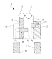
図1に示すものは、本発明の弁制御機構の実施例1の概略図である。該弁制御機構1は主に、第1弁揺腕13、第2弁揺腕14、第1駆動揺腕12、第2駆動揺腕15、第1連結ユニット18および第2連結ユニットより構成する。該第1弁揺腕13は第1弁10に連結し、該第2弁揺腕14は、該第2弁11に連結する。該第1弁10と該第2弁11はエンジン気筒(図示しない)のバルブで、該第1弁10と該第2弁11との開閉により、エンジンの吸気量を制御できる。該第1弁10と該第2弁11とエンジンとの配置は、公知技術のため、ここでの説明を省略する。
FIG. 1 is a schematic diagram of a first embodiment of the valve control mechanism of the present invention. The
該第1駆動揺腕12は該第1弁揺腕13の一端に設け、第1駆動揺腕12は第1カム16の駆動により運動を開始する。該第2駆動揺腕15は該第2弁揺腕14の一端に設け、第2駆動揺腕15は第2カム17の駆動により運動を開始する。該第1カム16と該第2カム17は、カムシャフト(図示しない)の駆動により回動する。本実施例において、該第1カム16は低揚程カム(mid cam)であり、該第2カム17は高揚程カム(high cam)である。すなわち、該第1カム16により、該第1駆動揺腕12の運動行程は該第2カム17より形成する行程により、該第2駆動揺腕15の運動行程より小さく発生する。該第1連結ユニット18は、該第1駆動揺腕12と該第1弁揺腕13との連結、または該第1弁揺腕13と該第2弁揺腕14との連結を選択できる。本実施例において、該第1連結ユニット18は二方向油圧駆動ピンを設ける。該第2連結ユニット19は、該第2駆動揺腕15と該第2弁揺腕14との連結、または該第2駆動揺腕15と該第2弁揺腕14との分離を選択できる。本実施例において、該第2連結ユニットは、閉鎖ピンを用いる。
The first
図3と図4を合わせて参照する。そのうち、図3は本発明の二方向油圧駆動ピンの概略図であり、図4は本発明の閉鎖ピンの概略図である。図3において、該二方向油圧駆動ピンの内部に収容空間180を設け、該収容空間180にピン体181を内設しピン体181の両側にオイルシート182を設ける。油回路Pc、Pbは該収容空間180に連絡する。これにより、油回路PbまたはPcの作動により、油体9より該ピン体181を該収容空間180の両端に移動させ、該第1駆動揺腕と該第1弁揺腕、および該第1弁揺腕と第2弁揺腕との連結を選択できる。図7を参照する。油回路Pc作動により、Pcの油圧がPbより高いとき、ピン体181は右側に移動し、該第1弁揺腕13と第2弁揺腕14に連結される。一方、該油回路Pbの作動により、Pbの油圧がPcより高いとき、ピン体181は左側に移動し、該第1駆動揺腕12と該第1弁揺腕13に連結される。
Please refer to FIG. 3 and FIG. 4 together. 3 is a schematic view of the two-way hydraulic drive pin of the present invention, and FIG. 4 is a schematic view of the closure pin of the present invention. In FIG. 3, an
図4に示すとおり、該閉鎖ピンはピン体191を有し、その内部に収容空間192を設ける。該収容空間192内部に弾性体193を設け、その一端はピン体191の内壁に連結し、他端は側面に取り付ける。該閉鎖ピンの一端に油回路Paを設ける。該閉鎖ピンの作動方式は、油回路Paより油体9を該閉鎖ピンに供給したとき、該ピン体191は油体9の押さえ力量により、オイルシート194を閉鎖ピンの他端(右側)に移動して、該ピン体191内部の弾性体193を圧迫し、弾性回復力を蓄積する。油回路Paに油体9が供給されないとき、該ピン体191に働く油圧は消える。このとき、該ピン体191内部の弾性体193で蓄積された弾性回復力を開放し、ピン体191を他端(左側)に移動させる。図1に示すとおり、該閉鎖ピン191を移動させ、該第2駆動揺腕15と該第2弁揺腕14との連結、または該第2駆動揺腕15と該第2弁揺腕14との分離を選択できる。
As shown in FIG. 4, the closing pin has a
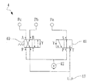
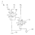
図2に示すものは、本発明の弁制御機構の実施例1の油回路制御の概略図である。該油回路制御ユニット4は、油回路Pa、Pb、Pc制御のために備える。2個の四口二位直動型電磁切換弁40、41を使用する。そのうち、A、Bは作動管線の継ぎ口であり、油回路Pa、Pb、Pcに連結する。Pは圧力源の継ぎ口であり、ポンプ42に連結する。Tは液体排出の継ぎ口であり、燃料タンク槽43に連結する。Yは制御弁の制御接点である。
FIG. 2 is a schematic diagram of oil circuit control according to the first embodiment of the valve control mechanism of the present invention. The oil circuit control unit 4 is provided for oil circuit Pa, Pb, and Pc control. Two four-port two-position direct acting
図5に示すとおり、Pa、Pb、Pcの油回路を制御し、該第1連結ユニット18と該第2連結ユニット19をさまざまな組み合わせにより、該第1弁10と第2弁11の弁体に異なる揚程パターンを形成できる。図1の例において、該第1連結ユニット18は該第1弁揺腕13および該第2弁揺腕14に連結し、該第2連結ユニット19は該第2弁揺腕14と該第2駆動揺腕15に連結する。該第1カム16が回転し、該第1駆動揺腕12に接触したとき、該第1連結ユニット18は該第1駆動揺腕12に接触していないため、該第1駆動揺腕12は単独に運動する。
As shown in FIG. 5, the oil circuit of Pa, Pb, Pc is controlled, and the valve body of the
一方、該第2カム17が回転するとき、該第2駆動揺腕15は該第2連結ユニット19を介して、該第2弁揺腕14に連結する。該第2弁揺腕14はさらに、該第1連結ユニット18を介して、該第1弁揺腕13に連結する。これにより、該第2カム17は該第2駆動揺腕15を伝動したとき、該第2駆動揺腕15は第2連結ユニット18、第一連結ユニット18を介して、該第1弁揺腕13、第2弁揺腕14を駆動する。該第2カム17は高揚程カム(high cam)のため、該第1弁10と該第2弁11は高揚程の開度を形成する。同じ原理で、他の運動行程の組み合わせは図5に示すとおり、弁10、11とも高揚程のとき、エンジンは高回転の馬力を形成する。弁10、11とも休止状態のとき、気筒休止状態となる。弁10と弁11がそれぞれ低揚程と高揚程のとき、エンジンは中速回転のスワール状態またはエンジン休止状態となる。
On the other hand, when the
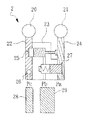
図6に示すものは、本発明の弁制御機構の実施例2の概略図である。該弁制御機構2は主に、第1弁揺腕22、第2弁揺腕24、駆動揺腕23、第1連結ユニット25、第2連結ユニット27および動力伝達ユニット26を備える。該第1弁揺腕22は第1弁20に連結し、該第1弁揺腕22は第1カム28の駆動により運動を開始する。該第2弁揺腕24は第2弁21に連結し、該第2弁21の開閉を制御する。該第1弁20および該第2弁21はエンジン気筒に設けて、吸気量の開閉機構を制御する。該第1弁20と該第2弁21とエンジンとの配置は、公知技術のため、ここでの説明を省略する。該駆動揺腕23は該第1弁揺腕22と該第2弁揺腕24の間に設け、該駆動揺腕23は第2カム29の駆動により運動を開始する。該第1カム28と該第2カム29は、カムシャフト(図示しない)の駆動により回転する。本実施例において、該第1カム28は低揚程カム(mid cam)であり、該第2カム29は高揚程カム(high cam)である。すなわち、該第1カム28により、該第1駆動揺腕22の運動行程は該第2カム29より形成する行程により、該第2駆動揺腕27の運動行程より小さく発生する。
FIG. 6 is a schematic diagram of a second embodiment of the valve control mechanism of the present invention. The
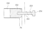
該第1連結ユニット25は、該駆動揺腕23と該第1弁揺腕22との連結、または該駆動揺腕23と該第2弁揺腕22との分離を選択できる。本実施例において、該第1連結ユニット25は、開放ピンを用いる。図7に示すものは、本発明の開放ピンの概略図である。該開放ピンに収容空間250を内設し、該収容空間250にピン体252を収容する。
該収容空間250の一端は油回路Pbに連結し、該ピン体252と棒体251に連結する。該棒体251は該収容空間250より該開放ピン外部に延ばしておく。棒体251の一端に係止め部材254を設け、該係止め部材254と該開放ピンの間に、弾性体253を該棒体251に装入する。
The
One end of the
油回路Pbの油圧働きが該ピン体252に伝達したとき、ピン体252を左側に移動し、該棒体251を移動して、該弾性体253を圧縮し、弾性回復力を蓄積する。油回路Pbの油圧が消えたとき、弾性体253の弾性回復力により、該ピン体252を右側に移動させる。図6を参照する。油回路Pbと該弾性体253を作動させ、該開放ピンを制御し、該駆動揺腕23と該第1駆動揺腕22との連結、または該駆動揺腕23と該第1弁揺腕22との分離を選択できる。該第2連結ユニット27は、該駆動揺腕23と該第2弁揺腕24との連結、または該駆動揺腕23と該第2弁揺腕24との分離を選択できる。本実施例において、該第2連結ユニット27は、閉鎖ピンを用いる。該閉鎖ピンの動作原理はい図4に示すとおりである。ここにて説明を省略する。
When the hydraulic action of the oil circuit Pb is transmitted to the
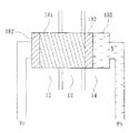
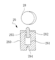
図8に示すものは、本発明の動力伝達ユニットの実施例1の概略図である。該動力伝達ユニット26は該第1弁揺腕(図示しない)に設け、円筒体260、ノックピン265および油回路制御ユニット(図示しない)を有する。該円筒体260に第1貫通孔262と限流孔264を設け、該第1貫通孔262と該限流孔264との間に収容空間261を設ける。該ノックピン265は該第1貫通孔262内部に設け、該ノックピン265の一端は該第1カム28に合わせて設ける。該ノックピン265は第1貫通孔262内部に移動できる。
FIG. 8 is a schematic diagram of
該油回路制御ユニットは該限流孔264に連結し、該油回路制御ユニットは該収容空間261に油体9を提供することにより、該ノックピン265を上方に移動させるか、または該収容空間261内部の油体9を解放して、ノックピン265を下方に移動させる。ノックピン265が上方に移動した後、該第1カム28よりの駆動力により、該第1弁揺腕13を連動して移動させる。該限流孔264の径は適切なサイズを設けることにより、該第1カム28と該ノックピン265と接触しても、該収容空間261内部の油体流出は緩やかのため、該動力伝達ユニットは収容空間内部の油体の圧縮不可特性により、きわめて良い剛性が得られる。一例として、2mm以下の限流孔は200Nのカム駆動力を担ぐことができる。油体を放出すると、ノックピン265は下向きとなり、該第1弁揺腕13は第1カム28の伝動力を受けることができない。本実施例において、該油回路制御ユニットは、たとえば図9の実施態様がる。ただし、この限りでない。
The oil circuit control unit is connected to the current limiting
図9に示すものは、本発明の弁制御機構の実施例2の油回路制御の概略図である。該油回路制御ユニット5は、油回路Pa、Pb、Pc制御のために備える。2個の四口二位直動型電磁切換弁50、51を使用する。そのうち、A、Bは作動管線の継ぎ口であり、油回路Pa、Pb、Pcに連結する。Pは圧力源の継ぎ口であり、ポンプ52に連結する。
Tは液体排出の継ぎ口であり、燃料タンク槽53に連結する。Yは制御弁の制御接点である。
FIG. 9 is a schematic diagram of oil circuit control in the second embodiment of the valve control mechanism of the present invention. The oil
T is a joint for discharging liquid and is connected to the
図10に示すとおり、Pa、Pb、Pcの油回路を制御し、該第1連結ユニット18と該第2連結ユニット19をさまざまな組み合わせにより、該第1弁10と第2弁11の弁体に異なる揚程パターンを形成できる。図6と図8を合わせて参照する。該動力伝達ユニット26は、油路Pcより油圧が供給されたため、ノックピン265は上方に移動する。
該第1連結ユニット25は該第1弁揺腕22と該駆動揺腕23と分離して設け、該第2連結ユニット27は該第2弁揺腕24と該駆動揺腕23を連結して設ける。前記の状態において、第1カム28(低揚程)が回動し、該動力伝達ユニット26に接触したとき、動力は該第1弁揺腕22に伝達される。ただし、該駆動揺腕23は該第1弁揺腕22に接触していないため、該第1弁揺腕22は単独に運動しながら、該第1弁20を連動し、低揚程開度を駆動する。
As shown in FIG. 10, the oil circuit of Pa, Pb, and Pc is controlled, and the valve body of the
The
該第2カム29(高揚程)が回動し、該駆動揺腕23は該第2連結ユニット27と該第2弁揺腕24に連結する。このとき、該第2カム29により該駆動揺腕23に連動したとき、該駆動揺腕23は該第2連結ユニット27を介して、該第2弁揺腕24を駆動し、該第2弁21の開度を操作する。該第2カム29は高揚程カムのため、該第2弁21は高揚程の開度を形成する。同じ原理の運動行程の組み合わせは、図10に示す。
The second cam 29 (high head) rotates, and the
図11に示すものは、本発明の弁制御機構の実施例2の概略図である。該弁制御機構3は主に、第1弁揺腕32、第2弁揺腕34、駆動揺腕33、第1連結ユニット35、第2連結ユニット37および動力伝達ユニット36を備える。該第1弁揺腕32は第1弁30に連結し、該第1弁揺腕32は第1カム38の駆動により運動を開始する。該第2弁揺腕34は第2弁31に連結し、該第2弁31の開閉を制御する。該駆動揺腕33は該第1弁揺腕32と該第2弁揺腕34の間に設け、該駆動揺腕33は第2カム33の駆動により運動を開始する。該第1カム38、該第2カム39、該第1弁揺腕32、第2弁揺腕34、該駆動揺腕33、該第1連結ユニット35、および該第2連結ユニット37との接続関係は、図6に同じ。ここにて説明を省略する。
FIG. 11 is a schematic view of a second embodiment of the valve control mechanism of the present invention. The
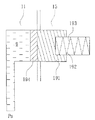
図12に示すものは、本発明の動力伝達ユニットの実施例2の概略図である。該動力伝達ユニット36は該第1弁揺腕32に設け、台座360、ノックピン361および第2ノックピン362を設ける。該台座360は第1収容空間363、第2収容空間365および油体9を提供するための油圧回路367を備える。該第1ノックピン361は、該第1収容空間363に内設し、該第1ノックピン361の底部はさらに第1弾性体364を設ける。該第1ノックピン361の一端に凹み部3611を設ける。該第2ノックピン362は該第2収容空間365に設け、その一部は該油圧回路367に連結し、該油圧回路と図11の油路Pcと連結する。該第2ノックピン362の底部に、第2弾性体366に連結し、該第2ノックピン362の一端は該液体と該第2弾性体366の働きにより、該凹み部3611への締結または切り離す選択できる。
FIG. 12 is a schematic diagram of
引き続き、該動力伝達ユニット36の動作を説明する。該第1弾性体364は外力の働きが状態のとき、該第1ノックピン361を押して、上方に移動させる。このとき、該油圧回路367の油圧が消えたとき、該第2弾性体366は外力がないため、第2弾性体366は該第2ノックピン362を前側に押して、該第2ノックピン362の端部3621を該凹み部3611に装入する。該第2ノックピン362を該凹み部3611に装入することにより、該第1ノックピン361を上方位置に取り付けて、該第1ノックピン361は該第1カム38に接触し、該第1カム38の動力を受けて、該第1弁揺腕32を連動して回動する。油圧回路367より油圧が供給されると、その油圧は該第2ノックピン362を右側に押して、該第2ノックピン362の端部3621を該凹み部3611より引き離す。このため、該第1カム38と該第1ノックピン361と接触するとき、該第1ノックピン361は該第2ノックピン362によって、支えられていないため、該第1カム38の伝動力は該第1弾性体364によって、吸収されて、動力は該第1弁揺腕32に伝達されない。
Next, the operation of the
図13に示すものは、本発明の弁制御機構の実施例3の油回路制御の概略図である。該油回路制御ユニット6は、油回路Pa、Pb、Pc制御のために備える。2個の四口二位直動型電磁切換弁61、62を使用する。そのうち、Aは作動管線の継ぎ口であり、油回路Pa、Pb、Pcに連結する。Pは圧力源の継ぎ口であり、ポンプ62に連結する。Tは液体排出の継ぎ口であり、燃料タンク槽63に連結する。Yは制御弁の制御接点である。
FIG. 13 is a schematic diagram of the oil circuit control of the third embodiment of the valve control mechanism of the present invention. The oil
図14に示すとおり、Pa、Pb、Pcの油回路を制御し、該第1連結ユニット18と該第2連結ユニット19をさまざまな組み合わせにより、該第1弁10と第2弁11の弁体に異なる揚程パターンを形成できる。図11と図12を合わせて参照する。該動力伝達ユニット36は油圧回路Pcに供給圧がないため、該第1ノックピン361は上向き位置に維持する。該第1連結ユニット35に油路Pbよりの油圧供給がないため、該第1弁揺腕32と該駆動揺腕33を分離し、該第2連結ユニット37に油路Paよりの油圧供給がないため、該第2弁揺腕34と該駆動揺腕33を連結する。前記の状態において、第1カム38(低揚程)が回動し、該動力伝達ユニット36に接触したとき、動力は該第1弁揺腕32に伝達される。ただし、該第1弁揺腕32に接触していないため、該第1弁揺腕32は単独に運動しながら、該第1弁30を連動し、低揚程開度を駆動する。
As shown in FIG. 14, the oil circuit of Pa, Pb, Pc is controlled, and the valve body of the
該第2カム39(高揚程)が回動し、該駆動揺腕33は該第2連結ユニット37と該第2弁揺腕34に連結する。このとき、該第2カム39により該駆動揺腕33に連動したとき、該駆動揺腕33は該第2連結ユニット37を介して、該第2弁揺腕34を駆動し連動する。該第2カム39は高揚程カムのため、該第2弁31は高揚程の開度を形成する。同じ原理の運動行程の組み合わせは、図14に示す。
The second cam 39 (high head) rotates, and the
前記のとおり、本発明の構造、特徴並びに各実施例を詳細説明しており、本発明の切り替えピン機構は、二つの切り替え弁と三つの油回路を介して、3種類以上の開閉パターンを形成できる。その目的並びに効果は実施進歩性が豊富のほか、産業上の利用価値もきわめて高い。市場でいままでにない運用に当たる。よって、特許法の精神に照らして、本発明は発明特許の用件に合致している。 As described above, the structure, features and embodiments of the present invention are described in detail, and the switching pin mechanism of the present invention forms three or more types of opening / closing patterns via two switching valves and three oil circuits. it can. Its purpose and effect are abundant in implementation, and its industrial utility value is very high. This is an unprecedented operation in the market. Thus, in light of the spirit of patent law, the present invention meets the requirements of invention patents.
1 弁制御機構
10 第1弁
11 第2弁
12 第1駆動揺腕
13 第1弁揺腕
14 第2弁揺腕
15 第2駆動揺腕
16 第1カム
17 第2カム
18 第1連結ユニット
180 収容空間
181 ピン体
182 オイルシート
19 第2連結ユニット
191 ピン体
192 収容空間
193 弾性部材
194 オイルシート
2 弁制御機構
20 第1弁
21 第2弁
22 第1弁揺腕
23 駆動揺腕
24 第1弁揺腕
25 第1連結ユニット
250 収容空間
251 棒体
252 ピン体
253 弾性部材
254 係止め部材
26 動力伝達ユニット
260 円筒体
261 収容空間
262 第1貫通孔
264 限流孔
265 ノックピン
27 第2連結ユニット
28 第1カム
29 第2カム
3 弁制御機構
30 第1弁
31 第2弁
32 第1弁揺腕
33 駆動揺腕
34 第1弁揺腕
35 第1連結ユニット
36 動力伝達ユニット
360 台座
361 第1ノックピン
3611 凹み部
362 第2ノックピン
3621 端部
363 第1収容空間
347 第1弾性体
365 第2収容空間
366 第2弾性体
367 油圧経路
37 第2連結ユニット
38 第1カム
39 第2カム
4、5、6 油回路制御ユニット
40、41、50、51、60、61 直動形電磁切換弁
42、52、62 ポンプ
43、53、63 燃料タンク
9 油体
Pa、Pb、Pc 油回路
1 valve control mechanism 10 first valve 11 second valve 12 first drive swing arm 13 first valve swing arm 14 second valve swing arm 15 second drive swing arm 16 first cam 17 second cam 18 first connection unit 180 Housing space 181 Pin body 182 Oil seat 19 Second connecting unit 191 Pin body 192 Housing space 193 Elastic member 194 Oil seat 2 Valve control mechanism 20 First valve 21 Second valve 22 First valve swing arm 23 Drive swing arm 24 First Valve swing arm 25 First connecting unit 250 Housing space 251 Rod body 252 Pin body 253 Elastic member 254 Locking member 26 Power transmission unit 260 Cylindrical body 261 Housing space 262 First through hole 264 Current limiting hole 265 Knock pin 27 Second connecting unit 28 First cam 29 Second cam 3 Valve control mechanism 30 First valve 31 Second valve 32 First valve swing arm 33 Drive swing arm 34 First valve swing arm 35 First connecting member Knit 36 Power transmission unit 360 Base 361 First knock pin 3611 Recessed portion 362 Second knock pin 3621 End portion 363 First accommodation space 347 First elastic body 365 Second accommodation space 366 Second elastic body 367 Hydraulic path 37 Second connection unit 38 First cam 39 Second cam 4, 5, 6 Oil circuit control unit 40, 41, 50, 51, 60, 61 Direct acting electromagnetic switching valve 42, 52, 62 Pump 43, 53, 63 Fuel tank 9 Oil body Pa , Pb, Pc Oil circuit
Claims (5)
該第1弁揺腕は第1弁に、該第2弁揺腕は第2弁にそれぞれ連結し、
該第1駆動揺腕は該第1弁揺腕の一端に設け、該第1駆動揺腕は、第1カムの駆動により運動を開始し、
該第2駆動揺腕は該第2弁揺腕の一端に設け、該第2駆動揺腕は、第2カムの駆動により運動を開始し、
該第1連結ユニットは、該第1駆動揺腕と該第1弁揺腕を連結するか、または該第1弁揺腕を該第2弁揺腕と連結するかを選択でき、
第2連結ユニットは、該第2駆動揺腕と該第2弁揺腕を連結するか分離するかを選択できることを特徴とする弁制御機構。 Including a first valve swing arm, a second valve swing arm, a first drive swing arm, a second drive swing arm, a first connection unit, a second connection unit,
The first valve swing arm is connected to the first valve, and the second valve swing arm is connected to the second valve.
The first drive swing arm is provided at one end of the first valve swing arm, and the first drive swing arm starts to move by driving the first cam;
The second drive swing arm is provided at one end of the second valve swing arm, and the second drive swing arm starts to move by driving the second cam,
The first connection unit can select whether to connect the first drive swing arm and the first valve swing arm or to connect the first valve swing arm to the second valve swing arm;
The valve control mechanism characterized in that the second connecting unit can select whether to connect or separate the second drive swing arm and the second valve swing arm.
該第1弁揺腕と該第2弁揺腕の間に設置されて、第2カムの駆動により駆動される駆動揺腕と、
選択的に該駆動揺腕を該第1弁揺腕と連結或いは分離させる第1連結ユニットと、
選択的に該駆動揺腕を該第2弁揺腕と連結或いは分離させる第2連結ユニットと、
を包含したバルブ制御機構において、
該第1弁揺腕に動力伝達ユニットを設け、該第1弁揺腕は該第1カムの伝動力を受け入れ、該動力伝達ユニットはさらに円筒体を有し、第1貫通孔と限流孔を設け、該第1貫通孔と限流孔との間に収容空間を設け、
ノックピンは該第1貫通孔内部に設け、該ノックピンの一端は該第1カムに合わせて設け、該ノックピンは第1貫通孔内部に移動でき、
油路制御ユニットは該限流孔に連結し、該油路制御ユニットは油体を該収容空間に流入と放出を選択操作できることを特徴とする弁制御機構。 A first valve swing arm connected to the first valve and driven by a first cam; a second valve swing arm connected to the second valve;
A drive swing arm installed between the first valve swing arm and the second valve swing arm and driven by driving of the second cam;
A first connection unit that selectively connects or separates the drive swing arm with the first valve swing arm;
A second connection unit that selectively connects or separates the drive swing arm with the second valve swing arm;
In the valve control mechanism including
The first valve swing arm is provided with a power transmission unit, the first valve swing arm receives the power transmitted from the first cam, the power transmission unit further includes a cylindrical body, a first through hole, and a current limiting hole. Providing an accommodation space between the first through hole and the current limiting hole,
A knock pin is provided in the first through hole, one end of the knock pin is provided in accordance with the first cam, the knock pin is movable in the first through hole,
An oil passage control unit is connected to the current limiting hole, and the oil passage control unit is capable of selectively operating an oil body to flow into and out of the accommodation space.
該第1弁揺腕と該第2弁揺腕の間に設置されて、第2カムの駆動により駆動される駆動揺腕と、A drive swing arm installed between the first valve swing arm and the second valve swing arm and driven by driving of the second cam;
選択的に該駆動揺腕を該第1弁揺腕と連結或いは分離させる第1連結ユニットと、A first connection unit that selectively connects or separates the drive swing arm with the first valve swing arm;
選択的に該駆動揺腕を該第2弁揺腕と連結或いは分離させる第2連結ユニットと、A second connection unit that selectively connects or separates the drive swing arm with the second valve swing arm;
を包含したバルブ制御機構において、In the valve control mechanism including
該第1弁揺腕に動力伝達ユニットを設けて、第1弁揺腕より該第1カムの伝動力を受け入れ、該動力伝達ユニットはさらに、台座、第1ノックピン及び第2ノックピンを含み、該台座は第1収容空間、第2収容空間および液体を提供するための油圧回路を備え、A power transmission unit is provided on the first valve swing arm to receive the power transmitted from the first cam from the first valve swing arm, and the power transmission unit further includes a base, a first knock pin, and a second knock pin, The pedestal includes a first accommodating space, a second accommodating space, and a hydraulic circuit for providing liquid,
該第1ノックピンは該第1収容空間に内設し、該第1ノックピンの底部はさらに第1弾性体を設け、該第1ノックピンの一端に凹み部を設け、The first knock pin is provided in the first accommodation space, the bottom of the first knock pin is further provided with a first elastic body, and a recess is provided at one end of the first knock pin;
該第2ノックピンは該第2収容空間に内設し、その一部は該油圧回路に連結し、該第2ノックピンの底部はさらに該第2弾性体に連結し、該第2ノックピンの一端は該液体と該第2弾性体の働きにより、該凹み部に締結するか、または引き離すことを選択できることを特徴とする弁制御機構。The second knock pin is provided in the second receiving space, a part of the second knock pin is connected to the hydraulic circuit, a bottom portion of the second knock pin is further connected to the second elastic body, and one end of the second knock pin is A valve control mechanism characterized in that it can be selected to be fastened to or pulled away from the recess by the action of the liquid and the second elastic body.
Applications Claiming Priority (1)
| Application Number | Priority Date | Filing Date | Title |
|---|---|---|---|
| TW095128974A TWI310804B (en) | 2006-08-08 | 2006-08-08 | Valve actuation mechansim |
Publications (2)
| Publication Number | Publication Date |
|---|---|
| JP2008038889A JP2008038889A (en) | 2008-02-21 |
| JP4516552B2 true JP4516552B2 (en) | 2010-08-04 |
Family
ID=39049341
Family Applications (1)
| Application Number | Title | Priority Date | Filing Date |
|---|---|---|---|
| JP2006249486A Expired - Fee Related JP4516552B2 (en) | 2006-08-08 | 2006-09-14 | Valve control mechanism |
Country Status (3)
| Country | Link |
|---|---|
| US (1) | US7721690B2 (en) |
| JP (1) | JP4516552B2 (en) |
| TW (1) | TWI310804B (en) |
Cited By (1)
| Publication number | Priority date | Publication date | Assignee | Title |
|---|---|---|---|---|
| CN109312645A (en) * | 2016-04-21 | 2019-02-05 | 伊顿智能动力有限公司 | Valve actuating mechanism component |
Families Citing this family (7)
| Publication number | Priority date | Publication date | Assignee | Title |
|---|---|---|---|---|
| TWI394887B (en) * | 2010-01-20 | 2013-05-01 | Kwang Yang Motor Co | Engine valve control device |
| DE102010036941B4 (en) * | 2010-08-11 | 2012-09-13 | Sauer-Danfoss Gmbh & Co. Ohg | Method and device for determining the state of an electrically controlled valve |
| US10400691B2 (en) | 2013-10-09 | 2019-09-03 | Tula Technology, Inc. | Noise/vibration reduction control |
| US9399964B2 (en) | 2014-11-10 | 2016-07-26 | Tula Technology, Inc. | Multi-level skip fire |
| US11236689B2 (en) | 2014-03-13 | 2022-02-01 | Tula Technology, Inc. | Skip fire valve control |
| US10233796B2 (en) * | 2014-05-12 | 2019-03-19 | Tula Technology, Inc. | Internal combustion engine using variable valve lift and skip fire control |
| US10662883B2 (en) | 2014-05-12 | 2020-05-26 | Tula Technology, Inc. | Internal combustion engine air charge control |
Family Cites Families (20)
| Publication number | Priority date | Publication date | Assignee | Title |
|---|---|---|---|---|
| AU551310B2 (en) | 1983-06-06 | 1986-04-24 | Honda Giken Kogyo Kabushiki Kaisha | Valve actuating mechanism |
| US4523550A (en) | 1983-09-22 | 1985-06-18 | Honda Giken Kogyo Kabushiki Kaisha | Valve disabling device for internal combustion engines |
| JPS6117107U (en) * | 1984-07-06 | 1986-01-31 | トヨタ自動車株式会社 | Valve mechanism of internal combustion engine |
| JPS6131610A (en) | 1984-07-24 | 1986-02-14 | Honda Motor Co Ltd | Internal combustion engine valve deactivation device |
| JPS62121811A (en) | 1985-07-31 | 1987-06-03 | Honda Motor Co Ltd | Internal combustion engine valve train |
| JPS63100210A (en) * | 1986-10-16 | 1988-05-02 | Honda Motor Co Ltd | Internal combustion engine valve train |
| US4887563A (en) | 1986-10-16 | 1989-12-19 | Honda Giken Kogyo Kabushiki Kaisha | Valve operating apparatus for an internal combustion engine |
| JPS63147909A (en) | 1986-10-23 | 1988-06-20 | Honda Motor Co Ltd | Valve operating state selector for internal combustion engine |
| JPH01155010A (en) * | 1987-12-12 | 1989-06-16 | Fuji Heavy Ind Ltd | Valve system of internal combustion engine |
| JPH0633712A (en) * | 1992-07-17 | 1994-02-08 | Mitsubishi Motors Corp | Valve train structure with variable valve timing mechanism |
| JP2936981B2 (en) * | 1993-12-17 | 1999-08-23 | 三菱自動車工業株式会社 | Internal combustion engine with variable valve mechanism |
| JP3253045B2 (en) * | 1994-08-25 | 2002-02-04 | 本田技研工業株式会社 | Valve train for multi-cylinder internal combustion engine |
| JP3319883B2 (en) * | 1994-08-31 | 2002-09-03 | 本田技研工業株式会社 | Valve train for internal combustion engine |
| DE19519601C2 (en) * | 1995-05-29 | 1997-04-03 | Daimler Benz Ag | Valve drive system for a multi-cylinder internal combustion engine |
| JP3938339B2 (en) | 2001-07-26 | 2007-06-27 | 本田技研工業株式会社 | Valve control device for internal combustion engine |
| JP4050571B2 (en) * | 2002-08-08 | 2008-02-20 | 本田技研工業株式会社 | Valve operating device for internal combustion engine |
| TWI222488B (en) | 2002-12-17 | 2004-10-21 | Mitsubishi Motors Corp | Valve system of internal combustion engine |
| US6966285B1 (en) | 2004-07-21 | 2005-11-22 | General Motors Corporation | Engine valve actuation control and method |
| JP4286235B2 (en) * | 2005-04-20 | 2009-06-24 | 株式会社オティックス | Variable valve mechanism for internal combustion engine |
| JP4535932B2 (en) * | 2005-05-09 | 2010-09-01 | 本田技研工業株式会社 | Engine valve gear |
-
2006
- 2006-08-08 TW TW095128974A patent/TWI310804B/en not_active IP Right Cessation
- 2006-09-14 JP JP2006249486A patent/JP4516552B2/en not_active Expired - Fee Related
-
2007
- 2007-04-17 US US11/785,372 patent/US7721690B2/en not_active Expired - Fee Related
Cited By (3)
| Publication number | Priority date | Publication date | Assignee | Title |
|---|---|---|---|---|
| CN109312645A (en) * | 2016-04-21 | 2019-02-05 | 伊顿智能动力有限公司 | Valve actuating mechanism component |
| CN109312645B (en) * | 2016-04-21 | 2021-09-03 | 伊顿智能动力有限公司 | Valve train assembly |
| US11976577B2 (en) | 2016-04-21 | 2024-05-07 | Eaton Intelligent Power Limited | Valve train assembly |
Also Published As
| Publication number | Publication date |
|---|---|
| JP2008038889A (en) | 2008-02-21 |
| US7721690B2 (en) | 2010-05-25 |
| TWI310804B (en) | 2009-06-11 |
| US20080035082A1 (en) | 2008-02-14 |
| TW200809076A (en) | 2008-02-16 |
Similar Documents
| Publication | Publication Date | Title |
|---|---|---|
| CN101929365B (en) | Hydraulic self-adaption air valve correct-timing variable system of diesel engine and control method thereof | |
| US7721690B2 (en) | Valve actuation mechanism | |
| CN103388502B (en) | A kind of full changeable electro-hydraulic air valve drive unit | |
| CN107676142B (en) | A hydraulically driven variable valve mechanism that controls high pressure with low pressure | |
| CN108590799A (en) | A kind of Fully variable valve train of hydraulic-driven | |
| KR100820694B1 (en) | Variable valve lift device | |
| CN107842408B (en) | Variable valve lift mechanism, method for controlling valve lift and engine | |
| JP4787785B2 (en) | Variable valve mechanism | |
| JP4286235B2 (en) | Variable valve mechanism for internal combustion engine | |
| CN102966390B (en) | Engine variable valve lift mechanism | |
| CN101163865B (en) | Valve mechanism for internal combustion engine | |
| CN201100150Y (en) | A valve driving supply device for engine | |
| CN201269121Y (en) | Switching structure of variable valve lift mechanism | |
| CN204900006U (en) | Valve transmission group in electrodeless variable valve lift and variable valve right time can realize | |
| CN100547230C (en) | Valve control mechanism | |
| TWI479076B (en) | Engine variable valve lift mechanism | |
| CN105781661B (en) | Engine intake valve backhaul controllable device and the air distribution system provided with the device | |
| CN105156167B (en) | Automobile engine compression brakes slow system | |
| CN214170643U (en) | Variable valve timing device | |
| CN211008803U (en) | Three-valve overhead double-camshaft engine distribution system | |
| CN101550848B (en) | valve control mechanism | |
| CN202091046U (en) | Electric control valve driving mechanism of automobile engine | |
| CN105179091B (en) | The slow system of automobile engine compression | |
| CN201100149Y (en) | A valve supply machine for engine | |
| JP6775402B2 (en) | Variable valve mechanism of internal combustion engine |
Legal Events
| Date | Code | Title | Description |
|---|---|---|---|
| A131 | Notification of reasons for refusal |
Free format text: JAPANESE INTERMEDIATE CODE: A131 Effective date: 20090428 |
|
| A601 | Written request for extension of time |
Free format text: JAPANESE INTERMEDIATE CODE: A601 Effective date: 20090728 |
|
| A602 | Written permission of extension of time |
Free format text: JAPANESE INTERMEDIATE CODE: A602 Effective date: 20090731 |
|
| A521 | Request for written amendment filed |
Free format text: JAPANESE INTERMEDIATE CODE: A523 Effective date: 20090828 |
|
| A131 | Notification of reasons for refusal |
Free format text: JAPANESE INTERMEDIATE CODE: A131 Effective date: 20091201 |
|
| A601 | Written request for extension of time |
Free format text: JAPANESE INTERMEDIATE CODE: A601 Effective date: 20100301 |
|
| A602 | Written permission of extension of time |
Free format text: JAPANESE INTERMEDIATE CODE: A602 Effective date: 20100304 |
|
| A521 | Request for written amendment filed |
Free format text: JAPANESE INTERMEDIATE CODE: A523 Effective date: 20100331 |
|
| TRDD | Decision of grant or rejection written | ||
| A01 | Written decision to grant a patent or to grant a registration (utility model) |
Free format text: JAPANESE INTERMEDIATE CODE: A01 Effective date: 20100427 |
|
| A01 | Written decision to grant a patent or to grant a registration (utility model) |
Free format text: JAPANESE INTERMEDIATE CODE: A01 |
|
| A61 | First payment of annual fees (during grant procedure) |
Free format text: JAPANESE INTERMEDIATE CODE: A61 Effective date: 20100514 |
|
| R150 | Certificate of patent or registration of utility model |
Ref document number: 4516552 Country of ref document: JP Free format text: JAPANESE INTERMEDIATE CODE: R150 Free format text: JAPANESE INTERMEDIATE CODE: R150 |
|
| FPAY | Renewal fee payment (event date is renewal date of database) |
Free format text: PAYMENT UNTIL: 20130521 Year of fee payment: 3 |
|
| R250 | Receipt of annual fees |
Free format text: JAPANESE INTERMEDIATE CODE: R250 |
|
| R250 | Receipt of annual fees |
Free format text: JAPANESE INTERMEDIATE CODE: R250 |
|
| R250 | Receipt of annual fees |
Free format text: JAPANESE INTERMEDIATE CODE: R250 |
|
| R250 | Receipt of annual fees |
Free format text: JAPANESE INTERMEDIATE CODE: R250 |
|
| R250 | Receipt of annual fees |
Free format text: JAPANESE INTERMEDIATE CODE: R250 |
|
| R250 | Receipt of annual fees |
Free format text: JAPANESE INTERMEDIATE CODE: R250 |
|
| R250 | Receipt of annual fees |
Free format text: JAPANESE INTERMEDIATE CODE: R250 |
|
| R250 | Receipt of annual fees |
Free format text: JAPANESE INTERMEDIATE CODE: R250 |
|
| LAPS | Cancellation because of no payment of annual fees |