US4523550A - Valve disabling device for internal combustion engines - Google Patents
Valve disabling device for internal combustion engines Download PDFInfo
- Publication number
- US4523550A US4523550A US06/652,816 US65281684A US4523550A US 4523550 A US4523550 A US 4523550A US 65281684 A US65281684 A US 65281684A US 4523550 A US4523550 A US 4523550A
- Authority
- US
- United States
- Prior art keywords
- rocker arm
- axial bore
- urging
- valve
- disabling device
- Prior art date
- Legal status (The legal status is an assumption and is not a legal conclusion. Google has not performed a legal analysis and makes no representation as to the accuracy of the status listed.)
- Expired - Lifetime
Links
Images


Classifications
-
- F—MECHANICAL ENGINEERING; LIGHTING; HEATING; WEAPONS; BLASTING
- F01—MACHINES OR ENGINES IN GENERAL; ENGINE PLANTS IN GENERAL; STEAM ENGINES
- F01L—CYCLICALLY OPERATING VALVES FOR MACHINES OR ENGINES
- F01L1/00—Valve-gear or valve arrangements, e.g. lift-valve gear
- F01L1/26—Valve-gear or valve arrangements, e.g. lift-valve gear characterised by the provision of two or more valves operated simultaneously by same transmitting-gear; peculiar to machines or engines with more than two lift-valves per cylinder
- F01L1/267—Valve-gear or valve arrangements, e.g. lift-valve gear characterised by the provision of two or more valves operated simultaneously by same transmitting-gear; peculiar to machines or engines with more than two lift-valves per cylinder with means for varying the timing or the lift of the valves
-
- F—MECHANICAL ENGINEERING; LIGHTING; HEATING; WEAPONS; BLASTING
- F01—MACHINES OR ENGINES IN GENERAL; ENGINE PLANTS IN GENERAL; STEAM ENGINES
- F01L—CYCLICALLY OPERATING VALVES FOR MACHINES OR ENGINES
- F01L2303/00—Manufacturing of components used in valve arrangements
- F01L2303/01—Tools for producing, mounting or adjusting, e.g. some part of the distribution
Definitions
- This invention relates to a valve disabling device for internal combustion engines mainly adapted for use in motorcycles and other vehicles.
- Conventional high output type internal combustion engines include a type which is equipped with a plurality of inlet valves and/or exhaust valves at each of the cylinders and thus adapted to permit large quantities of a mixture and/or exhaust gases to be supplied into and/or emitted from the engine cylinders. Also known in a valve disabling device for use with such high output type internal combustion engines, which is adapted to selectively hold the inlet valves and/or the exhaust valves in a first position wherein all the valves are rendered operative, and in a second position wherein part of the valves are rendered inoperative or disabled, to improve the output characteristic of the engine particularly in a low speed region.
- a conventional valve disabling device of this kind includes first and second rocker arms provided for a pair of inlet valves and/or exhaust valves, one of which is engaged with a cam forming part of the valve actuating mechanism, a piston disposed within a cylinder bore formed in the first rocker arm, in a manner projectable toward and retractable away from the second rocker arm, and a guide pin disposed within a guide bore formed in the second rocker arm and permanently urged toward the first rocker arm.
- the paired inlet valves and/or exhaust valves are actuated through the coupled rocker arms to make opening and closing actions in unison.
- the piston is forced out of the guide bore by the urging force of the guide pin, to disconnect the two rocker arms from each other.
- an oil pump which is driven by the engine to supply high pressure operating oil into the cylinder bore, is kept inoperative to hold the piston out of the guide bore by the urging force of the guide pin, thus holding the other one of the rocker arms not engaging the cam in a state disconnected from the same cam.
- each pair of the valves need to be opened and closed in synchronism with each other.
- the rocker arms which correspond to the paired valves it is necessary to subject the rocker arms which correspond to the paired valves to tappet adjustment, i.e. adjustment of the clearance between the cam and the rocker arms, with the rocker arms coupled together.
- the conventional valve disabling device is not provided with means for effecting such adjustment, making it difficult to perform with accuracy tappet adjustment of the rocker arm not engaging the cam during stoppage of the engine.
- the present invention provides a valve disabling device for use in a valve actuating mechanism of an internal combustion engine, wherein the valve actuating mechanism has cam means, and first and second rocker arm means, one of which engages the cam means.
- An engaging member and an urging member are slidably disposed, respectively, in first and second axial bores formed in the first and second rocker arm means.
- Pressure applying means is adapted to hydraulically force the engaging member into the second axial bore against the urging force of the urging member, whereby the first and second rocker arm means are drivingly coupled together to cause a pair of inlet valves or exhaust valves to make valving motions in unison with each other, while when the pressure applying means is inoperative, the engaging means is receded from the second axial bore through the urging member to thereby disconnect the first and second rocker arm means from each other to render part of the valves disabled.
- Biasing means is adapted to bias the engaging member into the second axial bore irrespective of whether the pressure applying means is operative or inoperative.
- the urging member is adapted to assume a predetermined position where a portion thereof is projected out of the second axial bore for access from outside.
- the urging member is retained in the predetermined position by means of retaining means with the first and second rocker arm means coupled together.
- FIG. 1 is a fragmentary longitudinal sectional view of an internal combustion engine equipped with a valve disabling device according to a first embodiment of the invention
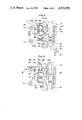
- FIG. 2 is a fragmentary sectional view taken along line II--II in FIG. 1, showing rocker arms in a disconnected state, and their peripheral parts;
- FIG. 3 is a view similar to FIG. 2, showing the rocker arms in a connected state
- FIG. 4 is a fragmentary sectional view taken along line IV--IV in FIG. 3;
- FIG. 5 is a view similar to FIG. 2, showing a valve disabling device according to a second embodiment of the invention, with the rocker arms maintained in a disconnected state;
- FIG. 6 is a view similar to FIG. 3, showing the rocker arms of FIG. 5 in a connected state;
- FIG. 7 is a side view of a tool for pulling and retaining a guide pin, which is used in a valve disabling device according to a third embodiment of the invention.
- FIG. 8 is a top plan view of the tool of FIG. 7;
- FIG. 9 is a sectional view taken along line IX--IX in FIG. 8;
- FIG. 10 is a fragmentary sectional view of the valve disabling device according to the third embodiment of the invention, with the tool of FIG. 7 engaged with the guide pin;
- FIG. 11 is a view similar to FIG. 10, showing the guide pin pulled out of its bore by means of the tool.
- FIG. 12 is a view similar to FIG. 10, showing the guide pin retained in the pulled-out position by means of the tool.
- FIGS. 1 through 4 there is shown a valve disabling device for an internal combustion engine, according to a first embodiment of the invention.
- the internal combustion engine 1 has a plurality of cylinders 2, only one of which is shown in FIG. 1, each equipped with a pair of inlet valves 13-1 and 13-2 (only one of them is shown) for establishing and interrupting the communication between an intake passage 3 and a combustion chamber 4, and a pair of exhaust valves 13'-1 and 13'-2 (only one of them is shown) for establishing and interrupting the communication between an exhaust passage 5 and the combustion chamber 4.
- First and second rocker arms 15-1 and 15-2 for actuating the respective inlet valves 13-1, 13-2 are pivotally journalled by a common inlet rocker arm shaft 16 fixed to a cylinder head 14, while first and second rocker arms 15'-1 and 15'-2 for actuating the respective exhaust valves 13'-1, 13'-2 are pivotally journalled by a common exhaust rocker arm shaft 16' also fixed to the cylinder head 14.
- Ends of the rocker arms 15-1 to 15'-2 remote from the associated rocker arm shaft 16, 16' are each formed with a tapped bore, not shown, in which a tappet adjusting screw 17-1 to 17'-2 is threadedly fitted for axial displacement therein.
- the screws 17-1 to 17'-2 have their inner or lower ends abut against outer or upper ends of valve stems 13-1a to 13'-2a of the respective valves 13-1 to 13'-2.
- the first inlet rocker arm 15-1 and the first exhaust rocker arm 15'-1 are each formed integrally with a cam slipper 18, 18' at its upper surface at an end portion remote from a corresponding one of the rocker arm shafts 16, 16', and are disposed in urging contact with a corresponding cam 19a, 19'a formed integrally with a camshaft 19, 19' at its outer periphery, through the cam slipper 18, 18'.
- reference numerals 6-1 to 6'-2 designate valve springs urging the respective inlet and exhaust valves 13-1 to 13'-2 in the directions of closing them.
- valve actuating mechanisms for the inlet valves 13-1, 13-2 and the exhaust valves 13'-1, 13'-2 have substantially the same structure, and accordingly valve disabling devices for these valves are substantially identical in structure with each other. Therefore, description given below is only directed to the inlet valve disabling device.
- the first inlet rocker arm 15-1 is formed therein with a first axial bore or cylinder bore 21, and the second inlet rocker arm 15-2 with a second axial bore or stepped guide bore 23 axially aligned with the cylinder bore 21, respectively.
- the cylinder bore 21 and the guide bore 23 have substantially the same diameter, and the cylinder bore 21 opens at its one end 21a facing the second rocker arm 15-2, while the guide bore 23 opens at its opposite ends 23a and 23b.
- a piston 20 Slidably received within the cylinder bore 21 is a piston 20 as an engaging member which is projectable into and retractable from the guide bore 23 through the open end 21a of the cylinder bore 21 and the open end 23a of the guide bore 23.
- the piston 20 cooperates with the cylinder bore 21 to define an oil chamber 21b on the side of an end wall 15-1b of the first rocker arm 15-1.
- This oil chamber 21b communicates with an oil feeding passage 16b formed in the inlet rocker arm shaft 16 along its axis, through a hole 16a formed through the peripheral wall of the shaft 16, and an oil passage 15-1a formed through the first rocker arm 15-1.
- the oil feeding passage 16b is in turn selectively communicated with an oil pump 24 of the engine 1 or with an oil return tank 26, through a control valve 25 formed of an electromagnetic three-way valve.
- reference numeral 40 denotes a compression spring interposed between the piston 20 and the first rocker arm 15-1 within the oil chamber 20 and permanently urging the piston 20 toward the second rocker arm 15-2.
- a guide pin 22 as an urging member is slidably received in the guide bore 23 of the second rocker arm 15-2 and partly projected outwardly from an end wall 15-2a of the second rocker arm 15-2 through the outer open end 23b of the guide bore 23.
- the guide pin 22 is formed of a one-piece member and comprises an enlarged inner end portion 22a having substantially the same diameter as the inner end portion of the stepped guide bore 23, an intermediate portion 22b having a diameter smaller than that of the inner end portion 22a and defining an annular spring chamber 41 in cooperation with the guide bore 23, and an outer end portion 22c projected out of the guide bore 23.
- the outer end portion 22c of the guide pin 22 has its outer peripheral surface formed with an annular groove 27 which is permanently located outside the second rocker arm 15-2.
- the intermediate portion 22b of the guide pin 22 is formed with a diametric through hole 29 at a predetermined axial location, while the inner end portion 22a is disposed to abut against a shoulder 23c formed in an axially intermediate inner peripheral surface of the guide bore 23, for limiting an axial extreme position of the guide pin 22 when it is pulled outward.
- a compression spring 42 is accommodated within the spring chamber 41 and interposed between the enlarged inner end portion 22a of the guide pin 22 and the end wall 15-2a of the second rocker arm 15-2 to urge the guide pin 22 toward the first rocker arm 15-1 with an urging force larger than the counteracting force exerted by the spring 40 accommodated within the oil chamber 21b.
- valve disabling device constructed as above operates as follows:
- the two coupled rocker arms 15-1, 15-2 make a unitary rocking motion about the shaft 16 so that the two inlet valves 13-1, 13-2 in urging contact with the respective rocker arms 15-1, 15-2 are forced to make concurrent closing and opening motions.
- the exhaust valve disabling device operates in the same manner as the inlet valve disabling device, to cause the two exhaust valves 13'-1, 13'-2 to make concurrent closing and opening motions.
- the stopper pin 30 has its outer peripheral surface urged against the outer surface of the end wall 15-2a of the second rocker arm 15-2 by the force of the spring 42. Then, the tappet adjusting screw 17-2 of the second rocker arm 15-2 is loosened to render the same rocker arm freely rockable to permit axially aligning the guide bore 23 in the second rocker arm 15-2 with the piston 20 of the first rocker arm 15-1 so that the piston 20 is partly fitted into the guide bore 23 by the urging force of the spring 40.
- a thickness gauge of a thickness equal to a required tappet clearance is interposed between the cam 19 and the cam slipper 18 of the first rocker arm 15-1.
- the tappet adjusting screw 17-1 is then rotated until the two members 18, 19 come into contact with the thickness gauge at its opposite faces, thereby setting a position of the first rocker arm 15-1, which is assumed when the associated inlet valve 13-1 is closed.
- the first and second rocker arms 15-1, 15-2 are coupled together, they assume the same angular position.
- the tappet adjustment for the second rocker arm 15-2 can be made by merely rotating the tappet adjusting screw 17-2 until the screw 17-2 abuts against the associated valve stem 13-2a of the inlet valve 13-2. Since the second rocker arm 15-2 does not directly engage the cam 19, the above tappet clearance is a virtual one for the second rocker arm 15-2 and defined as a clearance between the rocker arm 15-2 and a plane extending from the cam 19 in a position corresponding to a closed position of the inlet valves 13-1, 13-2.
- the coupled rocker arms 15-1, 15-2 cause the respective valve stems 13-1a, 13-2a to make concurrent downward motions as the cam 19 rotates, to thereby open the inlet valves 13-1, 13-2 concurrently.
- the stopper pin 30 is removed from the hole 29 so that the urging force of the guide pin 22, i.e. the force of the spring 42 acts upon the piston 20 to force same out of the guide bore 23 against the smaller force of the spring 40, to bring the rocker arms 15-1, 15-2 into a disconnected state which is normally assumed during stoppage of the engine. Since the urging force of the spring 40 acting upon the piston 20 is smaller than the counteracting force of the spring 42 acting upon the guide pin 22, the spring 40 does not hinder the piston 20 from being displaced by the guide pin 22 in the valve disabling direction, when the operating oil is discharged from the oil chamber 21b.
- FIGS. 5 and 6 show a valve disabling device according to a second embodiment of the invention, wherein means for pulling out the guide pin 22 and then retaining same in the predetermined pulled-out position is different from that of the first embodiment described above, and except for this, this embodiment is substantially identical in structure with the first embodiment.
- FIGS. 5 and 6 parts and elements appearing also in the first embodiment are designated by common numerals, and detailed explanation thereof is omitted.
- the end wall 15-1b of the first rocker arm 15-1 is formed with a through hole 15-1c through which a cylindrical portion 51 of a push rod 50 extends.
- the cylindrical portion 51 has a conical enlarged end 52 which has a larger diameter than the inner diameter of the through hole 15-1c, disposed to abut against the piston 20, to serve to prevent the push rod 50 from being slipped out of the hole 15-1c.
- the conical enlarged end 52 is also adapted to close an inner open end of the hole 15-1c in a liquidtight manner when pressurized operating oil is supplied to the cylinder bore 21, to thereby prevent leakage of the operating oil.
- An outer end of the cylindrical portion 51 is threaded, on which a spring seat member 53 is securedly screwed.
- a compression spring 54 is interposed between the spring seat member 53 and the end wall 15-1b of the first rocker arm 15-1 to permanently urge the push rod 50 in the axially outward direction.
- the push rod 50 is urgedly displaced in the axially inward direction with its outer end face by a screw driver 60 or like means, to axially force the guide pin 22 through the piston 20 into a predetermined pulled-out position.
- the tool 30 is inserted through the hole 29 of the guide pin 22 to temporarily hold the guide pin 22 in the above predetermined pulled-out position.
- the pressurized oil introduced into the oil chamber 21b acts upon the piston 20 to urge the end wall 15-2a of the second rocker arm 15-2 through the inner end portion 22a of the guide pin 22 and the spring 42, thereby drivingly coupling the two rocker arms 15-1, 15-2.
- valve disabling action and tappet adjustment of the second embodiment is substantially identical with those of the first embodiment, and therefore explanation thereof is omitted.
- the third embodiment is substantially identical in basic structure with the first embodiment, but different therefrom in that, according to the third embodiment, a tool 28' is employed in lieu of the tool 28 and the stopper pin 30 in the first embodiment, and the guide pin 22 does not have a diametric hole like the hole 29 formed therein. As shown in detail in FIGS.
- the tool 28' for pulling and retaining the guide pin 22 has a bar-like main body 70 formed of a metal plate bent into a U-shaped cross section, and a U-shaped elongate cut-out engaging portion 73 formed in an end 70a of the main body 70, with opposite lateral wall projections 71 extending from lateral walls 70c of the main body 70.
- a major portion of the main body 70 extending from the engaging portion 73 to the other end 70b is bent in the same direction of projection of the projection walls 71 through an angle of about 15 degrees with respect to the bottom wall of the tip 70a.
- Each of the projection walls 71 has a tapered end edge 71a.
- the tool 28' constructed as above is operated in the following manner: As shown in FIGS. 10 through 12, first, with the guide bore 23 of the second rocker arm 15-2 aligned with the cylinder bore 21 of the first rocker arm 15-1, the tip of the engaging portion 73 of the tool 28' is engaged in the groove 27 of the guide pin 22, and is held with the end edges 71a of the projection walls 71 abutting against the end wall 15-2a of the second rocker arm 15-2 as in the illustrated position of FIG. 10.
- the tool 28' With the tool 28' kept in the above position, the tool 28' is swung in the counterclockwise direction indicated by the arrow in FIG. 10 about a point of contact P of the tool 28' with the second rocker arm 15-2 until the projection walls 71 abut against the end wall 15-2a of the second rocker arm 15-2, as shown in FIG. 11.
- the guide pin 22 By thus moving the tool 28' in the counterclockwise direction in FIG. 10, the guide pin 22 is partly pulled out of the second rocker arm 15-2 in the direction away from the first rocker arm 15-1, against the urging force of the spring 42.
- the piston 21 is then correspondingly displaced toward the second rocker arm 15-2 by the urging force of the spring 40 into the guide bore 23 of the second rocker arm 15-2, thus drivingly coupling the two rocker arms 15-1, 15-2 through the piston 20.
- the tool 18' is pushed toward the valve disabling device nearly at right angles to the axis of the guide pin 22, as indicated by the arrow in FIG. 11, until the groove 27 of the guide pin 22 engages the engaging portion 73 of the tool 28' at its innermost portion, whereby the projection walls 71 are in contact with an outer surface of the end wall of the second rocker arm 15-2 on an axial extension of the guide bore 23, as shown in FIG. 12.
- the piston 20 is axially biased into contact with the guide pin by urging force of the spring 40, whereby the two rocker arms 15-1, 15-2 are drivingly coupled together through the piston 20, the guide pin 22 and the spring 42.
- the cams 19, 19' are disposed for engagement with the respective first rocker arms 15-1, 15'-1, which are formed therein with the oil chambers 21b, the cams 19, 19' may alternatively be disposed for engagement with the respective second rocker arms 15-2, 15'-2.
- the outer end of the guide pin 22 may be threaded and a nut may be threadedly fitted on the same outer end to retain the guide pin 22 in the predetermined position.
Landscapes
- Engineering & Computer Science (AREA)
- Mechanical Engineering (AREA)
- General Engineering & Computer Science (AREA)
- Valve-Gear Or Valve Arrangements (AREA)
- Valve Device For Special Equipments (AREA)
Abstract
Description
Claims (11)
Applications Claiming Priority (4)
| Application Number | Priority Date | Filing Date | Title |
|---|---|---|---|
| JP58174262A JPS6067708A (en) | 1983-09-22 | 1983-09-22 | Valve stopper in engine |
| JP58-174262 | 1983-09-22 | ||
| JP17426383A JPS6067709A (en) | 1983-09-22 | 1983-09-22 | Valve stopper in engine |
| JP58-174263 | 1983-09-22 |
Publications (1)
| Publication Number | Publication Date |
|---|---|
| US4523550A true US4523550A (en) | 1985-06-18 |
Family
ID=26495943
Family Applications (1)
| Application Number | Title | Priority Date | Filing Date |
|---|---|---|---|
| US06/652,816 Expired - Lifetime US4523550A (en) | 1983-09-22 | 1984-09-20 | Valve disabling device for internal combustion engines |
Country Status (1)
| Country | Link |
|---|---|
| US (1) | US4523550A (en) |
Cited By (33)
| Publication number | Priority date | Publication date | Assignee | Title |
|---|---|---|---|---|
| EP0186341A1 (en) * | 1984-12-24 | 1986-07-02 | General Motors Corporation | Engine valve train system |
| GB2182719A (en) * | 1985-11-09 | 1987-05-20 | Ford Motor Co | I.C. engine valve gear rocker arm disconnecting mechanism |
| US4727830A (en) * | 1985-07-31 | 1988-03-01 | Honda Giken Kogyo Kabushiki Kaisha | Valve operating mechanism for internal combustion engine |
| US4727831A (en) * | 1985-07-31 | 1988-03-01 | Honda Giken Kogyo Kabushiki Kaisha | Valve operating mechanism for internal combustion engine |
| US4741297A (en) * | 1985-07-31 | 1988-05-03 | Honda Giken Kogyo Kabushiki Kaisha | Valve operating mechanism for internal combustion engine |
| US4759322A (en) * | 1986-10-23 | 1988-07-26 | Honda Giken Kogyo Kabushiki Kaisha | Valve operating apparatus for an internal combustion engine |
| US4768475A (en) * | 1986-02-28 | 1988-09-06 | Fuji Jukogyo Kabushiki Kaisha | Valve mechanism for an automotive engine |
| US4777914A (en) * | 1986-08-27 | 1988-10-18 | Honda Giken Kogyo Kabushiki Kaisha | Valve operating apparatus for an internal combustion engine |
| US4790274A (en) * | 1986-07-30 | 1988-12-13 | Honda Giken Kogyo Kabushiki Kaisha | Valve operating mechanism for internal combustion engine |
| US4793296A (en) * | 1987-01-30 | 1988-12-27 | Honda Giken Kogyo Kabushiki Kaisha | Valve operating mechanism for internal combustion engine |
| US4799463A (en) * | 1986-11-18 | 1989-01-24 | Honda Giken Kogyo Kabushiki Kaisha | Valve operating mechanism for internal combustion engines |
| US4829948A (en) * | 1986-12-27 | 1989-05-16 | Honda Giken Kogyo Kabushiki Kaisha | Valve operating device for internal combustion engine |
| US4844022A (en) * | 1986-08-27 | 1989-07-04 | Honda Giken Kogyo Kabushiki Kaisha | Valve operating apparatus for an internal combustion engine |
| US4848285A (en) * | 1986-10-15 | 1989-07-18 | Honda Giken Kogyo Kabushiki Kaisha | Valve operating apparatus for an internal combustion engine |
| US4887563A (en) * | 1986-10-16 | 1989-12-19 | Honda Giken Kogyo Kabushiki Kaisha | Valve operating apparatus for an internal combustion engine |
| US4905639A (en) * | 1986-10-23 | 1990-03-06 | Honda Giken Kogyo Kabushiki Kaisha | Valve operating apparatus for an internal combustion engine |
| US4907550A (en) * | 1986-10-23 | 1990-03-13 | Honda Giken Kogyo Kabushiki Kaisha | Apparatus for changing operation timing of valves for internal combustion engine |
| USRE33310E (en) * | 1984-07-24 | 1990-08-28 | Honda Giken Kogyo Kabushiki Kaisha | Valve operating and interrupting mechanism for internal combustion engine |
| US4957076A (en) * | 1986-04-16 | 1990-09-18 | Honda Giken Kogyo Kabushiki Kaisha | Valve operating mechanism for an internal combustion engine |
| US4960083A (en) * | 1988-10-11 | 1990-10-02 | Honda Giken Kogyo Kabushiki Kaisha | Failsafe method in connection with valve timing-changeover control for internal combustion engines |
| US4962732A (en) * | 1987-07-13 | 1990-10-16 | Honda Giken Kogyo Kabushiki Kaisha | Valve operating device for internal combustion engine |
| US4986227A (en) * | 1990-05-08 | 1991-01-22 | Dewey Iii Albert B | Variable lift valve train |
| US5081971A (en) * | 1989-04-07 | 1992-01-21 | Honda Giken Kogyo Kabushiki Kaisha | Intake system for internal combustion engine |
| US5140953A (en) * | 1991-01-15 | 1992-08-25 | Fogelberg Henrik C | Dual displacement and expansion charge limited regenerative cam engine |
| USRE34553E (en) * | 1986-08-27 | 1994-03-01 | Honda Giken Kogyo Kabushiki Kaisha | Vale operating apparatus for an internal combustion engine |
| US5544626A (en) * | 1995-03-09 | 1996-08-13 | Ford Motor Company | Finger follower rocker arm with engine valve deactivator |
| US6223846B1 (en) * | 1998-06-15 | 2001-05-01 | Michael M. Schechter | Vehicle operating method and system |
| US6647954B2 (en) * | 1997-11-17 | 2003-11-18 | Diesel Engine Retarders, Inc. | Method and system of improving engine braking by variable valve actuation |
| EP1582705A2 (en) | 2004-03-29 | 2005-10-05 | BorgWarner Inc. | Variable lift and duration device for poppet valves |
| US20080035082A1 (en) * | 2006-08-08 | 2008-02-14 | Industrial Technology Research Institute | Valve actuation mechanism |
| US20110048819A1 (en) * | 2008-11-25 | 2011-03-03 | Yamaha Hatsudoki Kabushiki Kaisha | Variable valve apparatus, and an engine apparatus and a transport machine having the same |
| CN101550848B (en) * | 2006-08-15 | 2012-02-29 | 财团法人工业技术研究院 | Valve control mechanism |
| US10767517B2 (en) * | 2017-01-31 | 2020-09-08 | Schaeffler Technologies AG & Co. KG | Variable valve drive of a combustion piston engine |
Citations (8)
| Publication number | Priority date | Publication date | Assignee | Title |
|---|---|---|---|---|
| US4182289A (en) * | 1975-11-17 | 1980-01-08 | Nissan Motor Co., Limited | Variable valve timing system for internal combustion engine |
| US4188225A (en) * | 1978-04-10 | 1980-02-12 | Lumin, Inc. | Halftone screen with cell matrix |
| US4216748A (en) * | 1978-05-16 | 1980-08-12 | Honda Giken Kogyo Kabushiki Kaisha | Internal combustion engine with subsidiary combustion chamber |
| US4253434A (en) * | 1978-04-21 | 1981-03-03 | Toyota Jidosha Kogyo Kabushiki Kaisha | Variable valve event engine |
| US4285310A (en) * | 1978-05-25 | 1981-08-25 | Toyota Jidosha Kogyo Kabushiki Kaisha | Dual intake valve type internal combustion engine |
| JPS5783631A (en) * | 1980-11-13 | 1982-05-25 | Suzuki Motor Co Ltd | Internal combustion engine |
| US4354460A (en) * | 1979-05-09 | 1982-10-19 | Toyota Jidosha Kogyo Kabushiki Kaisha | Variable valve event engine |
| US4480617A (en) * | 1981-11-11 | 1984-11-06 | Honda Giken Kogyo Kabushiki Kaisha | Valve operation control apparatus in internal combustion engine |
-
1984
- 1984-09-20 US US06/652,816 patent/US4523550A/en not_active Expired - Lifetime
Patent Citations (9)
| Publication number | Priority date | Publication date | Assignee | Title |
|---|---|---|---|---|
| US4182289A (en) * | 1975-11-17 | 1980-01-08 | Nissan Motor Co., Limited | Variable valve timing system for internal combustion engine |
| US4188225A (en) * | 1978-04-10 | 1980-02-12 | Lumin, Inc. | Halftone screen with cell matrix |
| US4253434A (en) * | 1978-04-21 | 1981-03-03 | Toyota Jidosha Kogyo Kabushiki Kaisha | Variable valve event engine |
| US4216748A (en) * | 1978-05-16 | 1980-08-12 | Honda Giken Kogyo Kabushiki Kaisha | Internal combustion engine with subsidiary combustion chamber |
| US4285310A (en) * | 1978-05-25 | 1981-08-25 | Toyota Jidosha Kogyo Kabushiki Kaisha | Dual intake valve type internal combustion engine |
| US4354460A (en) * | 1979-05-09 | 1982-10-19 | Toyota Jidosha Kogyo Kabushiki Kaisha | Variable valve event engine |
| JPS5783631A (en) * | 1980-11-13 | 1982-05-25 | Suzuki Motor Co Ltd | Internal combustion engine |
| US4438743A (en) * | 1980-11-13 | 1984-03-27 | Suzuki Jidosha Kogyo Kabushiki Kaisha | Internal combustion engine |
| US4480617A (en) * | 1981-11-11 | 1984-11-06 | Honda Giken Kogyo Kabushiki Kaisha | Valve operation control apparatus in internal combustion engine |
Cited By (39)
| Publication number | Priority date | Publication date | Assignee | Title |
|---|---|---|---|---|
| USRE33310E (en) * | 1984-07-24 | 1990-08-28 | Honda Giken Kogyo Kabushiki Kaisha | Valve operating and interrupting mechanism for internal combustion engine |
| US4627391A (en) * | 1984-12-24 | 1986-12-09 | General Motors Corporation | Engine valve train system |
| EP0186341A1 (en) * | 1984-12-24 | 1986-07-02 | General Motors Corporation | Engine valve train system |
| US4727830A (en) * | 1985-07-31 | 1988-03-01 | Honda Giken Kogyo Kabushiki Kaisha | Valve operating mechanism for internal combustion engine |
| US4727831A (en) * | 1985-07-31 | 1988-03-01 | Honda Giken Kogyo Kabushiki Kaisha | Valve operating mechanism for internal combustion engine |
| US4741297A (en) * | 1985-07-31 | 1988-05-03 | Honda Giken Kogyo Kabushiki Kaisha | Valve operating mechanism for internal combustion engine |
| GB2182719A (en) * | 1985-11-09 | 1987-05-20 | Ford Motor Co | I.C. engine valve gear rocker arm disconnecting mechanism |
| US4768475A (en) * | 1986-02-28 | 1988-09-06 | Fuji Jukogyo Kabushiki Kaisha | Valve mechanism for an automotive engine |
| US4957076A (en) * | 1986-04-16 | 1990-09-18 | Honda Giken Kogyo Kabushiki Kaisha | Valve operating mechanism for an internal combustion engine |
| US4869214A (en) * | 1986-07-30 | 1989-09-26 | Honda Giken Kogyo Kabushiki Kaisha | Valve operating mechanism for internal combustion engine |
| USRE33411E (en) * | 1986-07-30 | 1990-10-30 | Honda Giken Kogyo Kabushiki Kaisha | Valve operating mechanism for internal combustion engine |
| US4790274A (en) * | 1986-07-30 | 1988-12-13 | Honda Giken Kogyo Kabushiki Kaisha | Valve operating mechanism for internal combustion engine |
| USRE34553E (en) * | 1986-08-27 | 1994-03-01 | Honda Giken Kogyo Kabushiki Kaisha | Vale operating apparatus for an internal combustion engine |
| US4844022A (en) * | 1986-08-27 | 1989-07-04 | Honda Giken Kogyo Kabushiki Kaisha | Valve operating apparatus for an internal combustion engine |
| US4777914A (en) * | 1986-08-27 | 1988-10-18 | Honda Giken Kogyo Kabushiki Kaisha | Valve operating apparatus for an internal combustion engine |
| US4848285A (en) * | 1986-10-15 | 1989-07-18 | Honda Giken Kogyo Kabushiki Kaisha | Valve operating apparatus for an internal combustion engine |
| US4887563A (en) * | 1986-10-16 | 1989-12-19 | Honda Giken Kogyo Kabushiki Kaisha | Valve operating apparatus for an internal combustion engine |
| US4905639A (en) * | 1986-10-23 | 1990-03-06 | Honda Giken Kogyo Kabushiki Kaisha | Valve operating apparatus for an internal combustion engine |
| US4907550A (en) * | 1986-10-23 | 1990-03-13 | Honda Giken Kogyo Kabushiki Kaisha | Apparatus for changing operation timing of valves for internal combustion engine |
| US4759322A (en) * | 1986-10-23 | 1988-07-26 | Honda Giken Kogyo Kabushiki Kaisha | Valve operating apparatus for an internal combustion engine |
| US4799463A (en) * | 1986-11-18 | 1989-01-24 | Honda Giken Kogyo Kabushiki Kaisha | Valve operating mechanism for internal combustion engines |
| US4829948A (en) * | 1986-12-27 | 1989-05-16 | Honda Giken Kogyo Kabushiki Kaisha | Valve operating device for internal combustion engine |
| US4793296A (en) * | 1987-01-30 | 1988-12-27 | Honda Giken Kogyo Kabushiki Kaisha | Valve operating mechanism for internal combustion engine |
| US4962732A (en) * | 1987-07-13 | 1990-10-16 | Honda Giken Kogyo Kabushiki Kaisha | Valve operating device for internal combustion engine |
| US4960083A (en) * | 1988-10-11 | 1990-10-02 | Honda Giken Kogyo Kabushiki Kaisha | Failsafe method in connection with valve timing-changeover control for internal combustion engines |
| US5081971A (en) * | 1989-04-07 | 1992-01-21 | Honda Giken Kogyo Kabushiki Kaisha | Intake system for internal combustion engine |
| US4986227A (en) * | 1990-05-08 | 1991-01-22 | Dewey Iii Albert B | Variable lift valve train |
| US5140953A (en) * | 1991-01-15 | 1992-08-25 | Fogelberg Henrik C | Dual displacement and expansion charge limited regenerative cam engine |
| US5544626A (en) * | 1995-03-09 | 1996-08-13 | Ford Motor Company | Finger follower rocker arm with engine valve deactivator |
| US6647954B2 (en) * | 1997-11-17 | 2003-11-18 | Diesel Engine Retarders, Inc. | Method and system of improving engine braking by variable valve actuation |
| US6223846B1 (en) * | 1998-06-15 | 2001-05-01 | Michael M. Schechter | Vehicle operating method and system |
| US6971355B2 (en) | 2004-03-29 | 2005-12-06 | Borgwarner Inc. | Variable lift and duration device for poppet valves |
| EP1582705A2 (en) | 2004-03-29 | 2005-10-05 | BorgWarner Inc. | Variable lift and duration device for poppet valves |
| US20080035082A1 (en) * | 2006-08-08 | 2008-02-14 | Industrial Technology Research Institute | Valve actuation mechanism |
| US7721690B2 (en) | 2006-08-08 | 2010-05-25 | Industrial Technology Research Institute | Valve actuation mechanism |
| CN101550848B (en) * | 2006-08-15 | 2012-02-29 | 财团法人工业技术研究院 | Valve control mechanism |
| US20110048819A1 (en) * | 2008-11-25 | 2011-03-03 | Yamaha Hatsudoki Kabushiki Kaisha | Variable valve apparatus, and an engine apparatus and a transport machine having the same |
| US8387575B2 (en) * | 2008-11-25 | 2013-03-05 | Yamaha Hatsudoki Kabushiki Kaisha | Variable valve apparatus, and an engine apparatus and a transport machine having the same |
| US10767517B2 (en) * | 2017-01-31 | 2020-09-08 | Schaeffler Technologies AG & Co. KG | Variable valve drive of a combustion piston engine |
Similar Documents
| Publication | Publication Date | Title |
|---|---|---|
| US4523550A (en) | Valve disabling device for internal combustion engines | |
| US4612884A (en) | Valve operating and interrupting mechanism for internal combustion engine | |
| US4576128A (en) | Valve operation stopping means for multi-cylinder engine | |
| US4556025A (en) | Engine valve mechanism having valve disabling device | |
| US4726332A (en) | Variable valve mechanism for internal combustion engines | |
| EP0265191B1 (en) | Valve operating mechanism in an internal combustion engine | |
| US5544628A (en) | Valve control arrangement for an internal combustion engine | |
| PL179720B1 (en) | Method of using a four-stroke internal combustion engine for braking | |
| US8051814B2 (en) | Engine | |
| CA1308980C (en) | Valve operating device for internal combustion engine | |
| JPH04301108A (en) | Hydraulic lifter with valve stopping device | |
| JPH06101437A (en) | Valve system of engine | |
| US4793296A (en) | Valve operating mechanism for internal combustion engine | |
| JPS5457009A (en) | Operating cylinder number control system for engine | |
| JPH0568604B2 (en) | ||
| JP2007146844A (en) | Tappet for internal combustion engine | |
| US8051815B2 (en) | Engine | |
| JPH0144885B2 (en) | ||
| JPH037526Y2 (en) | ||
| JPH0417706A (en) | Valve actuating device of engine | |
| JPH025885B2 (en) | ||
| JPH0118801Y2 (en) | ||
| JPH0329526Y2 (en) | ||
| JPH0351885B2 (en) | ||
| JPS6140882Y2 (en) |
Legal Events
| Date | Code | Title | Description |
|---|---|---|---|
| AS | Assignment |
Owner name: HONDA GIKEN KOGYO KABUSIKI KAISHA NO 27-8 6-CHOME Free format text: ASSIGNMENT OF ASSIGNORS INTEREST.;ASSIGNORS:HONDA, SHOICHI;NAKANO, YOSHIKATSU;MAKOTO, HIRANO;AND OTHERS;REEL/FRAME:004317/0058 Effective date: 19840911 Owner name: HONDA GIKEN KOGYO KABUSIKI KAISHA A CORP OF JAPAN, Free format text: ASSIGNMENT OF ASSIGNORS INTEREST;ASSIGNORS:HONDA, SHOICHI;NAKANO, YOSHIKATSU;MAKOTO, HIRANO;AND OTHERS;REEL/FRAME:004317/0058 Effective date: 19840911 |
|
| STCF | Information on status: patent grant |
Free format text: PATENTED CASE |
|
| FPAY | Fee payment |
Year of fee payment: 4 |
|
| FPAY | Fee payment |
Year of fee payment: 8 |
|
| FPAY | Fee payment |
Year of fee payment: 12 |