JP4497113B2 - Hybrid vehicle - Google Patents
Hybrid vehicle Download PDFInfo
- Publication number
- JP4497113B2 JP4497113B2 JP2006072834A JP2006072834A JP4497113B2 JP 4497113 B2 JP4497113 B2 JP 4497113B2 JP 2006072834 A JP2006072834 A JP 2006072834A JP 2006072834 A JP2006072834 A JP 2006072834A JP 4497113 B2 JP4497113 B2 JP 4497113B2
- Authority
- JP
- Japan
- Prior art keywords
- cooling
- cooling medium
- electric motor
- pcu
- path
- Prior art date
- Legal status (The legal status is an assumption and is not a legal conclusion. Google has not performed a legal analysis and makes no representation as to the accuracy of the status listed.)
- Expired - Fee Related
Links
- 238000001816 cooling Methods 0.000 claims description 103
- 230000007246 mechanism Effects 0.000 claims description 85
- 239000002826 coolant Substances 0.000 claims description 47
- 238000006243 chemical reaction Methods 0.000 claims description 21
- XLYOFNOQVPJJNP-UHFFFAOYSA-N water Substances O XLYOFNOQVPJJNP-UHFFFAOYSA-N 0.000 claims description 7
- 230000005484 gravity Effects 0.000 claims 2
- 239000000498 cooling water Substances 0.000 description 61
- 239000003507 refrigerant Substances 0.000 description 8
- 238000001514 detection method Methods 0.000 description 7
- LYCAIKOWRPUZTN-UHFFFAOYSA-N Ethylene glycol Chemical compound OCCO LYCAIKOWRPUZTN-UHFFFAOYSA-N 0.000 description 6
- 230000005540 biological transmission Effects 0.000 description 6
- 238000010586 diagram Methods 0.000 description 4
- 230000020169 heat generation Effects 0.000 description 4
- XEEYBQQBJWHFJM-UHFFFAOYSA-N Iron Chemical compound [Fe] XEEYBQQBJWHFJM-UHFFFAOYSA-N 0.000 description 3
- 230000008859 change Effects 0.000 description 3
- 238000002485 combustion reaction Methods 0.000 description 3
- 229910052802 copper Inorganic materials 0.000 description 3
- 239000010949 copper Substances 0.000 description 3
- 238000005192 partition Methods 0.000 description 3
- 230000004044 response Effects 0.000 description 3
- RYGMFSIKBFXOCR-UHFFFAOYSA-N Copper Chemical compound [Cu] RYGMFSIKBFXOCR-UHFFFAOYSA-N 0.000 description 2
- LFQSCWFLJHTTHZ-UHFFFAOYSA-N Ethanol Chemical compound CCO LFQSCWFLJHTTHZ-UHFFFAOYSA-N 0.000 description 2
- 230000001133 acceleration Effects 0.000 description 2
- 239000003990 capacitor Substances 0.000 description 2
- 239000000446 fuel Substances 0.000 description 2
- JEIPFZHSYJVQDO-UHFFFAOYSA-N iron(III) oxide Inorganic materials O=[Fe]O[Fe]=O JEIPFZHSYJVQDO-UHFFFAOYSA-N 0.000 description 2
- 238000000034 method Methods 0.000 description 2
- 230000002093 peripheral effect Effects 0.000 description 2
- 230000008569 process Effects 0.000 description 2
- 238000005086 pumping Methods 0.000 description 2
- 230000001172 regenerating effect Effects 0.000 description 2
- 230000001360 synchronised effect Effects 0.000 description 2
- HBBGRARXTFLTSG-UHFFFAOYSA-N Lithium ion Chemical compound [Li+] HBBGRARXTFLTSG-UHFFFAOYSA-N 0.000 description 1
- 206010037660 Pyrexia Diseases 0.000 description 1
- 230000004308 accommodation Effects 0.000 description 1
- 238000009835 boiling Methods 0.000 description 1
- 239000003795 chemical substances by application Substances 0.000 description 1
- 150000001879 copper Chemical class 0.000 description 1
- 238000005260 corrosion Methods 0.000 description 1
- 230000007797 corrosion Effects 0.000 description 1
- 230000005669 field effect Effects 0.000 description 1
- 230000004907 flux Effects 0.000 description 1
- 230000017525 heat dissipation Effects 0.000 description 1
- 239000003112 inhibitor Substances 0.000 description 1
- 238000009413 insulation Methods 0.000 description 1
- 229910052742 iron Inorganic materials 0.000 description 1
- 229910001416 lithium ion Inorganic materials 0.000 description 1
- 229910052987 metal hydride Inorganic materials 0.000 description 1
- 229910044991 metal oxide Inorganic materials 0.000 description 1
- 150000004706 metal oxides Chemical class 0.000 description 1
- 230000004048 modification Effects 0.000 description 1
- 238000012986 modification Methods 0.000 description 1
- 229910052759 nickel Inorganic materials 0.000 description 1
- PXHVJJICTQNCMI-UHFFFAOYSA-N nickel Substances [Ni] PXHVJJICTQNCMI-UHFFFAOYSA-N 0.000 description 1
- -1 nickel metal hydride Chemical class 0.000 description 1
- 230000003449 preventive effect Effects 0.000 description 1
- 230000009467 reduction Effects 0.000 description 1
- 239000004065 semiconductor Substances 0.000 description 1
Images


Classifications
-
- B—PERFORMING OPERATIONS; TRANSPORTING
- B60—VEHICLES IN GENERAL
- B60K—ARRANGEMENT OR MOUNTING OF PROPULSION UNITS OR OF TRANSMISSIONS IN VEHICLES; ARRANGEMENT OR MOUNTING OF PLURAL DIVERSE PRIME-MOVERS IN VEHICLES; AUXILIARY DRIVES FOR VEHICLES; INSTRUMENTATION OR DASHBOARDS FOR VEHICLES; ARRANGEMENTS IN CONNECTION WITH COOLING, AIR INTAKE, GAS EXHAUST OR FUEL SUPPLY OF PROPULSION UNITS IN VEHICLES
- B60K6/00—Arrangement or mounting of plural diverse prime-movers for mutual or common propulsion, e.g. hybrid propulsion systems comprising electric motors and internal combustion engines ; Control systems therefor, i.e. systems controlling two or more prime movers, or controlling one of these prime movers and any of the transmission, drive or drive units Informative references: mechanical gearings with secondary electric drive F16H3/72; arrangements for handling mechanical energy structurally associated with the dynamo-electric machine H02K7/00; machines comprising structurally interrelated motor and generator parts H02K51/00; dynamo-electric machines not otherwise provided for in H02K see H02K99/00
- B60K6/20—Arrangement or mounting of plural diverse prime-movers for mutual or common propulsion, e.g. hybrid propulsion systems comprising electric motors and internal combustion engines ; Control systems therefor, i.e. systems controlling two or more prime movers, or controlling one of these prime movers and any of the transmission, drive or drive units Informative references: mechanical gearings with secondary electric drive F16H3/72; arrangements for handling mechanical energy structurally associated with the dynamo-electric machine H02K7/00; machines comprising structurally interrelated motor and generator parts H02K51/00; dynamo-electric machines not otherwise provided for in H02K see H02K99/00 the prime-movers consisting of electric motors and internal combustion engines, e.g. HEVs
- B60K6/42—Arrangement or mounting of plural diverse prime-movers for mutual or common propulsion, e.g. hybrid propulsion systems comprising electric motors and internal combustion engines ; Control systems therefor, i.e. systems controlling two or more prime movers, or controlling one of these prime movers and any of the transmission, drive or drive units Informative references: mechanical gearings with secondary electric drive F16H3/72; arrangements for handling mechanical energy structurally associated with the dynamo-electric machine H02K7/00; machines comprising structurally interrelated motor and generator parts H02K51/00; dynamo-electric machines not otherwise provided for in H02K see H02K99/00 the prime-movers consisting of electric motors and internal combustion engines, e.g. HEVs characterised by the architecture of the hybrid electric vehicle
- B60K6/44—Series-parallel type
- B60K6/445—Differential gearing distribution type
-
- B—PERFORMING OPERATIONS; TRANSPORTING
- B60—VEHICLES IN GENERAL
- B60K—ARRANGEMENT OR MOUNTING OF PROPULSION UNITS OR OF TRANSMISSIONS IN VEHICLES; ARRANGEMENT OR MOUNTING OF PLURAL DIVERSE PRIME-MOVERS IN VEHICLES; AUXILIARY DRIVES FOR VEHICLES; INSTRUMENTATION OR DASHBOARDS FOR VEHICLES; ARRANGEMENTS IN CONNECTION WITH COOLING, AIR INTAKE, GAS EXHAUST OR FUEL SUPPLY OF PROPULSION UNITS IN VEHICLES
- B60K6/00—Arrangement or mounting of plural diverse prime-movers for mutual or common propulsion, e.g. hybrid propulsion systems comprising electric motors and internal combustion engines ; Control systems therefor, i.e. systems controlling two or more prime movers, or controlling one of these prime movers and any of the transmission, drive or drive units Informative references: mechanical gearings with secondary electric drive F16H3/72; arrangements for handling mechanical energy structurally associated with the dynamo-electric machine H02K7/00; machines comprising structurally interrelated motor and generator parts H02K51/00; dynamo-electric machines not otherwise provided for in H02K see H02K99/00
- B60K6/20—Arrangement or mounting of plural diverse prime-movers for mutual or common propulsion, e.g. hybrid propulsion systems comprising electric motors and internal combustion engines ; Control systems therefor, i.e. systems controlling two or more prime movers, or controlling one of these prime movers and any of the transmission, drive or drive units Informative references: mechanical gearings with secondary electric drive F16H3/72; arrangements for handling mechanical energy structurally associated with the dynamo-electric machine H02K7/00; machines comprising structurally interrelated motor and generator parts H02K51/00; dynamo-electric machines not otherwise provided for in H02K see H02K99/00 the prime-movers consisting of electric motors and internal combustion engines, e.g. HEVs
- B60K6/22—Arrangement or mounting of plural diverse prime-movers for mutual or common propulsion, e.g. hybrid propulsion systems comprising electric motors and internal combustion engines ; Control systems therefor, i.e. systems controlling two or more prime movers, or controlling one of these prime movers and any of the transmission, drive or drive units Informative references: mechanical gearings with secondary electric drive F16H3/72; arrangements for handling mechanical energy structurally associated with the dynamo-electric machine H02K7/00; machines comprising structurally interrelated motor and generator parts H02K51/00; dynamo-electric machines not otherwise provided for in H02K see H02K99/00 the prime-movers consisting of electric motors and internal combustion engines, e.g. HEVs characterised by apparatus, components or means specially adapted for HEVs
- B60K6/36—Arrangement or mounting of plural diverse prime-movers for mutual or common propulsion, e.g. hybrid propulsion systems comprising electric motors and internal combustion engines ; Control systems therefor, i.e. systems controlling two or more prime movers, or controlling one of these prime movers and any of the transmission, drive or drive units Informative references: mechanical gearings with secondary electric drive F16H3/72; arrangements for handling mechanical energy structurally associated with the dynamo-electric machine H02K7/00; machines comprising structurally interrelated motor and generator parts H02K51/00; dynamo-electric machines not otherwise provided for in H02K see H02K99/00 the prime-movers consisting of electric motors and internal combustion engines, e.g. HEVs characterised by apparatus, components or means specially adapted for HEVs characterised by the transmission gearings
- B60K6/365—Arrangement or mounting of plural diverse prime-movers for mutual or common propulsion, e.g. hybrid propulsion systems comprising electric motors and internal combustion engines ; Control systems therefor, i.e. systems controlling two or more prime movers, or controlling one of these prime movers and any of the transmission, drive or drive units Informative references: mechanical gearings with secondary electric drive F16H3/72; arrangements for handling mechanical energy structurally associated with the dynamo-electric machine H02K7/00; machines comprising structurally interrelated motor and generator parts H02K51/00; dynamo-electric machines not otherwise provided for in H02K see H02K99/00 the prime-movers consisting of electric motors and internal combustion engines, e.g. HEVs characterised by apparatus, components or means specially adapted for HEVs characterised by the transmission gearings with the gears having orbital motion
-
- B—PERFORMING OPERATIONS; TRANSPORTING
- B60—VEHICLES IN GENERAL
- B60L—PROPULSION OF ELECTRICALLY-PROPELLED VEHICLES; SUPPLYING ELECTRIC POWER FOR AUXILIARY EQUIPMENT OF ELECTRICALLY-PROPELLED VEHICLES; ELECTRODYNAMIC BRAKE SYSTEMS FOR VEHICLES IN GENERAL; MAGNETIC SUSPENSION OR LEVITATION FOR VEHICLES; MONITORING OPERATING VARIABLES OF ELECTRICALLY-PROPELLED VEHICLES; ELECTRIC SAFETY DEVICES FOR ELECTRICALLY-PROPELLED VEHICLES
- B60L50/00—Electric propulsion with power supplied within the vehicle
- B60L50/10—Electric propulsion with power supplied within the vehicle using propulsion power supplied by engine-driven generators, e.g. generators driven by combustion engines
- B60L50/16—Electric propulsion with power supplied within the vehicle using propulsion power supplied by engine-driven generators, e.g. generators driven by combustion engines with provision for separate direct mechanical propulsion
-
- B—PERFORMING OPERATIONS; TRANSPORTING
- B60—VEHICLES IN GENERAL
- B60W—CONJOINT CONTROL OF VEHICLE SUB-UNITS OF DIFFERENT TYPE OR DIFFERENT FUNCTION; CONTROL SYSTEMS SPECIALLY ADAPTED FOR HYBRID VEHICLES; ROAD VEHICLE DRIVE CONTROL SYSTEMS FOR PURPOSES NOT RELATED TO THE CONTROL OF A PARTICULAR SUB-UNIT
- B60W10/00—Conjoint control of vehicle sub-units of different type or different function
- B60W10/30—Conjoint control of vehicle sub-units of different type or different function including control of auxiliary equipment, e.g. air-conditioning compressors or oil pumps
-
- B—PERFORMING OPERATIONS; TRANSPORTING
- B60—VEHICLES IN GENERAL
- B60W—CONJOINT CONTROL OF VEHICLE SUB-UNITS OF DIFFERENT TYPE OR DIFFERENT FUNCTION; CONTROL SYSTEMS SPECIALLY ADAPTED FOR HYBRID VEHICLES; ROAD VEHICLE DRIVE CONTROL SYSTEMS FOR PURPOSES NOT RELATED TO THE CONTROL OF A PARTICULAR SUB-UNIT
- B60W20/00—Control systems specially adapted for hybrid vehicles
-
- B—PERFORMING OPERATIONS; TRANSPORTING
- B60—VEHICLES IN GENERAL
- B60K—ARRANGEMENT OR MOUNTING OF PROPULSION UNITS OR OF TRANSMISSIONS IN VEHICLES; ARRANGEMENT OR MOUNTING OF PLURAL DIVERSE PRIME-MOVERS IN VEHICLES; AUXILIARY DRIVES FOR VEHICLES; INSTRUMENTATION OR DASHBOARDS FOR VEHICLES; ARRANGEMENTS IN CONNECTION WITH COOLING, AIR INTAKE, GAS EXHAUST OR FUEL SUPPLY OF PROPULSION UNITS IN VEHICLES
- B60K1/00—Arrangement or mounting of electrical propulsion units
- B60K1/02—Arrangement or mounting of electrical propulsion units comprising more than one electric motor
-
- B—PERFORMING OPERATIONS; TRANSPORTING
- B60—VEHICLES IN GENERAL
- B60K—ARRANGEMENT OR MOUNTING OF PROPULSION UNITS OR OF TRANSMISSIONS IN VEHICLES; ARRANGEMENT OR MOUNTING OF PLURAL DIVERSE PRIME-MOVERS IN VEHICLES; AUXILIARY DRIVES FOR VEHICLES; INSTRUMENTATION OR DASHBOARDS FOR VEHICLES; ARRANGEMENTS IN CONNECTION WITH COOLING, AIR INTAKE, GAS EXHAUST OR FUEL SUPPLY OF PROPULSION UNITS IN VEHICLES
- B60K1/00—Arrangement or mounting of electrical propulsion units
- B60K2001/003—Arrangement or mounting of electrical propulsion units with means for cooling the electrical propulsion units
-
- B—PERFORMING OPERATIONS; TRANSPORTING
- B60—VEHICLES IN GENERAL
- B60L—PROPULSION OF ELECTRICALLY-PROPELLED VEHICLES; SUPPLYING ELECTRIC POWER FOR AUXILIARY EQUIPMENT OF ELECTRICALLY-PROPELLED VEHICLES; ELECTRODYNAMIC BRAKE SYSTEMS FOR VEHICLES IN GENERAL; MAGNETIC SUSPENSION OR LEVITATION FOR VEHICLES; MONITORING OPERATING VARIABLES OF ELECTRICALLY-PROPELLED VEHICLES; ELECTRIC SAFETY DEVICES FOR ELECTRICALLY-PROPELLED VEHICLES
- B60L2210/00—Converter types
- B60L2210/20—AC to AC converters
-
- Y—GENERAL TAGGING OF NEW TECHNOLOGICAL DEVELOPMENTS; GENERAL TAGGING OF CROSS-SECTIONAL TECHNOLOGIES SPANNING OVER SEVERAL SECTIONS OF THE IPC; TECHNICAL SUBJECTS COVERED BY FORMER USPC CROSS-REFERENCE ART COLLECTIONS [XRACs] AND DIGESTS
- Y02—TECHNOLOGIES OR APPLICATIONS FOR MITIGATION OR ADAPTATION AGAINST CLIMATE CHANGE
- Y02T—CLIMATE CHANGE MITIGATION TECHNOLOGIES RELATED TO TRANSPORTATION
- Y02T10/00—Road transport of goods or passengers
- Y02T10/60—Other road transportation technologies with climate change mitigation effect
- Y02T10/62—Hybrid vehicles
-
- Y—GENERAL TAGGING OF NEW TECHNOLOGICAL DEVELOPMENTS; GENERAL TAGGING OF CROSS-SECTIONAL TECHNOLOGIES SPANNING OVER SEVERAL SECTIONS OF THE IPC; TECHNICAL SUBJECTS COVERED BY FORMER USPC CROSS-REFERENCE ART COLLECTIONS [XRACs] AND DIGESTS
- Y02—TECHNOLOGIES OR APPLICATIONS FOR MITIGATION OR ADAPTATION AGAINST CLIMATE CHANGE
- Y02T—CLIMATE CHANGE MITIGATION TECHNOLOGIES RELATED TO TRANSPORTATION
- Y02T10/00—Road transport of goods or passengers
- Y02T10/60—Other road transportation technologies with climate change mitigation effect
- Y02T10/70—Energy storage systems for electromobility, e.g. batteries
-
- Y—GENERAL TAGGING OF NEW TECHNOLOGICAL DEVELOPMENTS; GENERAL TAGGING OF CROSS-SECTIONAL TECHNOLOGIES SPANNING OVER SEVERAL SECTIONS OF THE IPC; TECHNICAL SUBJECTS COVERED BY FORMER USPC CROSS-REFERENCE ART COLLECTIONS [XRACs] AND DIGESTS
- Y02—TECHNOLOGIES OR APPLICATIONS FOR MITIGATION OR ADAPTATION AGAINST CLIMATE CHANGE
- Y02T—CLIMATE CHANGE MITIGATION TECHNOLOGIES RELATED TO TRANSPORTATION
- Y02T10/00—Road transport of goods or passengers
- Y02T10/60—Other road transportation technologies with climate change mitigation effect
- Y02T10/7072—Electromobility specific charging systems or methods for batteries, ultracapacitors, supercapacitors or double-layer capacitors
-
- Y—GENERAL TAGGING OF NEW TECHNOLOGICAL DEVELOPMENTS; GENERAL TAGGING OF CROSS-SECTIONAL TECHNOLOGIES SPANNING OVER SEVERAL SECTIONS OF THE IPC; TECHNICAL SUBJECTS COVERED BY FORMER USPC CROSS-REFERENCE ART COLLECTIONS [XRACs] AND DIGESTS
- Y02—TECHNOLOGIES OR APPLICATIONS FOR MITIGATION OR ADAPTATION AGAINST CLIMATE CHANGE
- Y02T—CLIMATE CHANGE MITIGATION TECHNOLOGIES RELATED TO TRANSPORTATION
- Y02T10/00—Road transport of goods or passengers
- Y02T10/60—Other road transportation technologies with climate change mitigation effect
- Y02T10/72—Electric energy management in electromobility
Description
この発明は、エンジンおよび電動機を備えるハイブリッド車両に関し、特に電動機および電動機を駆動するための電力変換部を冷却可能に構成されたハイブリッド車両に関する。 The present invention relates to a hybrid vehicle including an engine and an electric motor, and more particularly to a hybrid vehicle configured to cool an electric motor and a power conversion unit for driving the electric motor.
近年、環境に配慮した自動車として、ハイブリッド車両(Hybrid Vehicle)が大きく注目されている。ハイブリッド車両は、従来のエンジンに加え、二次電池からなる蓄電部と、蓄電部からの電力により作動する電動機とをさらに駆動源とする自動車である。 In recent years, hybrid vehicles have attracted much attention as environmentally friendly vehicles. A hybrid vehicle is an automobile that further includes a power storage unit including a secondary battery and an electric motor that is operated by electric power from the power storage unit in addition to a conventional engine.
ハイブリッド車両では、電動機のトルクおよび回転数を最適に制御することで、エンジンの燃焼効率を高めている。このような電動機制御を実現するために、ハイブリッド車両は、インバータなどの電力変換部を備えている。電力変換部は、蓄電部から直流電力を受け、所定の電圧、周波数および位相などをもつ交流電力に変換して電動機へ与える。 In hybrid vehicles, the combustion efficiency of the engine is increased by optimally controlling the torque and rotation speed of the electric motor. In order to realize such electric motor control, the hybrid vehicle includes a power conversion unit such as an inverter. The power conversion unit receives DC power from the power storage unit, converts the DC power into AC power having a predetermined voltage, frequency, phase, and the like and supplies the AC power to the motor.
ところで、電動機は、コイルの抵抗成分に起因する銅損や鉄心を通過する交流磁束に起因する鉄損などにより発熱を生じる。また、電力変換部は、IGBT(Insulated Gate Bipolar Transistor)などのスイッチング素子におけるスイッチング損失により発熱を生じる。ここで、電動機における発熱の主たるものは銅損であり、この銅損は、電動機の出力に伴って増大する。一方、電力変換部におけるスイッチング損失は、スイッチング周波数が同一であれば、電力によらず略一定である。すなわち、発生する車両駆動力に応じて電動機における発熱量は変化するが、電力変換部における発熱量はほとんど変化しない。 By the way, the electric motor generates heat due to a copper loss caused by a resistance component of the coil, an iron loss caused by an AC magnetic flux passing through the iron core, and the like. The power conversion unit generates heat due to switching loss in a switching element such as an IGBT (Insulated Gate Bipolar Transistor). Here, the main thing of the heat_generation | fever in an electric motor is a copper loss, and this copper loss increases with the output of an electric motor. On the other hand, if the switching frequency is the same, the switching loss in the power converter is substantially constant regardless of the power. That is, the amount of heat generated in the electric motor changes according to the generated vehicle driving force, but the amount of heat generated in the power converter hardly changes.
このように、ハイブリッド車両においては、エンジンに加えて、電動機および電力変換部を冷却する必要がある。そこで、たとえば特開2004−112855号公報(特許文献1)には、冷媒圧送用ポンプの駆動用電動機を廃してコストを削減するとともに、車両重量が増大しないようにしたシリーズ式のハイブリッド車両が開示されている。このハイブリッド車両によれば、エンジンの出力軸に連結される発電機と、発電機の軸に連結され冷媒を圧送する第1冷媒圧送用ポンプと、発電機の軸に連結され冷媒を圧送する第2冷媒圧送用ポンプとを備え、第1冷媒圧送用ポンプにより圧送される冷媒による冷却対象を電動機とする一方、第2冷媒圧送用ポンプにより圧送される冷媒による冷却対象をインバータとする。 Thus, in a hybrid vehicle, it is necessary to cool an electric motor and a power converter in addition to an engine. Thus, for example, Japanese Patent Application Laid-Open No. 2004-112855 (Patent Document 1) discloses a series-type hybrid vehicle in which the motor for driving the refrigerant pressure pump is eliminated to reduce costs and the vehicle weight is not increased. Has been. According to this hybrid vehicle, the generator connected to the output shaft of the engine, the first refrigerant pump for pumping the refrigerant connected to the shaft of the generator, and the first pump for pumping the refrigerant connected to the shaft of the generator. The refrigerant is pumped by the refrigerant pumped by the first refrigerant pump, and the object to be cooled by the refrigerant pumped by the second pump is the inverter.
なお、シリーズ式ハイブリッド車両とは、エンジンの出力軸に連結された発電機から電力を受ける電動機のみが車両駆動力を発生し、エンジンは車両駆動力を発生しないハイブリッド車両である。
特許文献1に開示される構成は、シリーズ式ハイブリッド車両、すなわち走行中は常にエンジンおよび発電機が作動することを前提としている。しかしながら、実用化されている多くのハイブリッド車両は、より高い燃焼効率(燃費)を実現するために、エンジンおよび電動機のいずれからも車両駆動力を発生可能に構成されたパラレル式、もしくはパラレル式の構成にシリーズ式の要素をさらに加えたパラレル/シリーズ式を採用している。このようなパラレル式およびパラレル/シリアル式ハイブリッド車両においては、走行状況に応じてエンジンは間欠的に停止する。そのため、特許文献1に開示される構成をパラレル式およびパラレル/シリアル式ハイブリッド車両に適用することはできなかった。 The configuration disclosed in Patent Document 1 is based on the assumption that a series hybrid vehicle, that is, an engine and a generator always operate during traveling. However, in order to realize higher combustion efficiency (fuel consumption), many hybrid vehicles in practical use are parallel type or parallel type configured to generate vehicle driving force from either the engine or the electric motor. The parallel / series type is added to the configuration with series type elements added. In such a parallel type and parallel / serial type hybrid vehicle, the engine is intermittently stopped according to the traveling state. Therefore, the configuration disclosed in Patent Document 1 cannot be applied to a parallel type and parallel / serial type hybrid vehicle.
この発明は、このような問題点を解決するためになされたものであって、その目的は、エンジンおよび電動機の各々が車両駆動力を発生可能に構成されたハイブリッド車両において、電動機および電力変換部を安定して冷却できるハイブリッド車両を提供することである。 The present invention has been made to solve such problems, and an object of the present invention is to provide an electric motor and a power converter in a hybrid vehicle in which each of the engine and the electric motor is configured to be able to generate a vehicle driving force. It is providing the hybrid vehicle which can cool stably.
この発明によれば、各々が車両駆動力を発生可能に構成されたエンジンおよび電動機と、充放電可能に構成された蓄電部と、蓄電部から受けた電力を電動機を駆動するために変換する電力変換部と、第1の冷却媒体を介して電動機を冷却する第1の冷却機構と、第2の冷却媒体を介して電力変換部を冷却する第2の冷却機構とを備えたハイブリッド車両である。そして、第1の冷却機構は、第1の冷却媒体を熱交換して冷却する第1の熱交換部と、電動機および第1の熱交換部を含んで形成される第1の循環経路に第1の冷却媒体を循環させるための第1の送出機構とを含み、第2の冷却機構は、第2の冷却媒体を熱交換して冷却する第2の熱交換部と、電力変換部および第2の熱交換部を含んで形成される第2の循環経路に第2の冷却媒体を流動させる第2の送出機構とを含み、エンジンは、走行状況に応じて間欠的に停止し、第1および第2の送出機構は、エンジン停止中であっても作動可能に構成される。 According to the present invention, an engine and an electric motor each configured to be able to generate a vehicle driving force, an electric storage unit configured to be chargeable / dischargeable, and electric power for converting electric power received from the electric storage unit to drive the electric motor The hybrid vehicle includes a conversion unit, a first cooling mechanism that cools the electric motor via the first cooling medium, and a second cooling mechanism that cools the power conversion unit via the second cooling medium. . The first cooling mechanism includes a first heat exchange unit that exchanges heat to cool the first cooling medium, and a first circulation path that includes the electric motor and the first heat exchange unit. A first delivery mechanism for circulating one cooling medium, and the second cooling mechanism includes a second heat exchanging unit that exchanges heat to cool the second cooling medium, a power conversion unit, and a first And a second delivery mechanism that causes the second cooling medium to flow in a second circulation path formed including the two heat exchange units, and the engine stops intermittently according to the traveling state, and the first The second delivery mechanism is configured to be operable even when the engine is stopped.
この発明によれば、電動機を冷却する第1の冷却機構と、電力変換部を冷却する第2の冷却機構とを備え、第1および第2の冷却機構は、それぞれエンジン停止中であっても作動可能に構成された第1および第2の送出機構を含む。これにより、エンジン停止中であっても第1および第2の冷却媒体が循環されて冷却能力を発揮できる。 According to this invention, the first cooling mechanism that cools the electric motor and the second cooling mechanism that cools the power conversion unit are provided, and the first and second cooling mechanisms are respectively in a state where the engine is stopped. First and second delivery mechanisms configured to be operable are included. As a result, even when the engine is stopped, the first and second cooling media are circulated and the cooling capacity can be exhibited.
また、この発明によれば、互いに冷却要求の異なる電動機および電力変換部のそれぞれに対応して第1および第2の熱交換部が備えられる。これにより、電動機および電力変換部における冷却要求をそれぞれ満足させるように第1および第2の熱交換部の冷却性能(たとえば、大きさなど)を効率的に設計することができる。 Moreover, according to this invention, the 1st and 2nd heat exchange part is provided corresponding to each of the electric motor and electric power conversion part from which cooling requirements mutually differ. Thereby, the cooling performance (for example, magnitude | size etc.) of the 1st and 2nd heat exchange part can be designed efficiently so that the cooling request | requirement in an electric motor and a power converter part may be satisfied, respectively.
したがって、走行状況に応じてエンジンが間欠的に停止するハイブリッド車両において、電動機および電力変換部を安定して冷却することができる。 Therefore, in the hybrid vehicle in which the engine is intermittently stopped according to the traveling state, the electric motor and the power conversion unit can be stably cooled.
好ましくは、第1および第2の送出機構は、電気的に作動する。
好ましくは、第1の冷却機構は、第1の冷却媒体を電動機を構成するコイルに直接接触させて冷却する経路を含んで構成される。
Preferably, the first and second delivery mechanisms are electrically operated.
Preferably, the first cooling mechanism includes a path for cooling the first cooling medium by directly contacting the first cooling medium with a coil constituting the electric motor.
好ましくは、第2の冷却機構は、両端が第2の循環経路と接続され、電力変換部を含み、かつ第2の熱交換部を含まない経路に第2の冷却媒体を循環可能なように形成されたバイパス経路と、電力変換部から出力された第2の冷却媒体が第2の熱交換部およびバイパス経路のいずれか一方を流れるように切換え可能に構成された経路切換部と、第2の冷却媒体の温度に基づいて経路切換部を制御する制御部とをさらに含む。 Preferably, both ends of the second cooling mechanism are connected to the second circulation path, include the power conversion unit, and allow the second cooling medium to be circulated through the path not including the second heat exchange unit. A path switching unit configured to be switchable so that the formed bypass path, the second cooling medium output from the power conversion unit flows through one of the second heat exchange unit and the bypass path, and a second And a control unit that controls the path switching unit based on the temperature of the cooling medium.
好ましくは、制御部は、第2の冷却媒体の温度が所定値以上であるときに、電力変換部および第2の熱交換部を含む経路に第2の冷却媒体を循環させるように経路切換部を制御する一方、第2の冷却媒体の温度が所定値以上でないときに、電力変換部を含み、かつ第2の熱交換部を含まない経路に第2の冷却媒体を循環させるように経路切換部を制御する。 Preferably, the control unit is configured to circulate the second cooling medium in a path including the power conversion unit and the second heat exchanging unit when the temperature of the second cooling medium is equal to or higher than a predetermined value. On the other hand, when the temperature of the second cooling medium is not equal to or higher than the predetermined value, the path is switched so that the second cooling medium is circulated through the path including the power conversion unit and not including the second heat exchange unit Control part.
好ましくは、第1の冷却媒体は、油からなる。
好ましくは、第2の冷却媒体は、水からなる。
Preferably, the first cooling medium is made of oil.
Preferably, the second cooling medium is made of water.
この発明によれば、エンジンおよび電動機の各々が車両駆動力を発生可能に構成されたハイブリッド車両において、電動機および電力変換部を安定して冷却できるハイブリッド車両を実現できる。 According to the present invention, in a hybrid vehicle in which each of the engine and the electric motor is configured to be able to generate a vehicle driving force, it is possible to realize a hybrid vehicle capable of stably cooling the electric motor and the power conversion unit.
この発明の実施の形態について、図面を参照しながら詳細に説明する。なお、図中の同一または相当部分については、同一符号を付してその説明は繰返さない。 Embodiments of the present invention will be described in detail with reference to the drawings. Note that the same or corresponding parts in the drawings are denoted by the same reference numerals and description thereof will not be repeated.
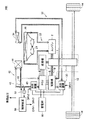
図1は、この発明の実施の形態に従うハイブリッド車両100の概略構成図である。
図1を参照して、ハイブリッド車両100は、エンジン2と、蓄電部16と、トランスアクスル1と、PCU(パワーコントロールユニット)8とを備える。
FIG. 1 is a schematic configuration diagram of a
Referring to FIG. 1,
エンジン2は、ガソリン等の燃料の燃焼による熱エネルギを源として駆動軸10を回転駆動させ、駆動輪14の駆動力を発生する。
The
蓄電部16は、PCU8と電気的に接続されて充放電可能に構成され、一例として、ニッケル水素電池やリチウムイオン電池などの充放電可能な二次電池、もしくは電気二重層キャパシタなどの大容量キャパシタで構成される。そして、蓄電部16は、PCU8から供給される直流電力を受けて電気エネルギーを蓄える一方、蓄えた電気エネルギーを直流電力としてPCU8へ供給する。
The
トランスアクスル1は、トランスミッションとアクスル(車軸)とが一体構造として構成されており、電動機6と、発電機7と、動力伝達機構4とを有する。そして、トランスアクスル1は、同一の駆動軸10を介して機械的に結合可能なエンジン2および電動機6から回転駆動力を受け、車輪軸12へ伝達可能に構成される。すなわち、トランスアクスル1は、エンジン2および電動機6の少なくとも一方からの回転駆動力を受けて、車輪軸12を介して駆動輪14の車両駆動力を発生する。
The transaxle 1 includes a transmission and an axle (axle) as an integral structure, and includes an
電動機6は、PCU8と電気的に接続され、PCU8から受けた交流電力に応じて、所定トルクの回転駆動力を発生する。そして、電動機6が発生した回転駆動力は、駆動軸10を介してエンジン2の回転駆動力とともに動力伝達機構4へ伝達可能に構成される。また、電動機6は、ハイブリッド車両100の回生制動時において、駆動輪14を介して与えられる運動エネルギーから電気エネルギー(交流電力)を発生し、その発生した交流電力をPCU8へ供給する。発電機7は、駆動軸10の回転駆動力の一部を受けて、交流電力を発生し、PCU8へ供給する。一例として、電動機6および発電機7は、三相交流電力に同期して回転する同期電動機であり、特に永久磁石が埋め込まれたロータを有する永久磁石型同期電動機からなる。
The
動力伝達機構4は、駆動軸10と車輪軸12との間に配置され、駆動軸10を介して入力される回転駆動力を車輪軸12へ伝達する一方、その一部の回転駆動力を発電機7へ伝達する。具体的には、動力伝達機構4は、プラネタリギアなどの変速機構を兼ねた動力分割機構を含み、図示しない外部ECU(Electrical Control Unit)などからの変速指令に応じて、駆動軸10からの入力回転数に対する車輪軸12への出力回転数の比率(変速比)を変化させる。
The power transmission mechanism 4 is disposed between the
PCU8は、蓄電部16から供給される直流電力を、図示しない外部ECUなどからのトルク指令および回転数指令などに従い、所定の電圧、周波数および位相をもつ電動機6を駆動するための交流電力に変換して、トランスアクスル1の電動機6へ供給する。また、回生制動時に電動機6が発生する交流電力を変換して蓄電部16を充電する。さらに、PCU8は、発電機7から供給される交流電力を受けて、電動機6および蓄電部16の少なくとも一方へ供給する。そして、PCU8は、IGBT(Insulated Gate Bipolar Transistor)やパワーMOSFET(Metal Oxide Semiconductor Field Effect Transistor)などのスイッチング素子を含む三相ブリッジ回路などからなる。
The PCU 8 converts the DC power supplied from the
上述したハイブリッド車両100は、走行状況に応じてエンジン2を間欠的に停止する。具体的には、図示しないECUが、運転者の操作によるアクセルペダルの踏込量、ブレーキペダルの踏込量およびシフトレバーの選択ポジションなどに応じて、エンジン2および電動機6に要求する車両駆動力を決定し、エンジン2に対する車両駆動力の要求がゼロになる場合には、エンジン2を停止する。そして、車速が所定値以上となった場合や急加速が要求された場合には、エンジン2を始動して、エンジン2から車両駆動力を発生する。
The
ハイブリッド車両100は、エンジンラジエタ20と、ラジエタファン24と、冷却水循環経路22と、電動機ラジエタ34と、冷却油循環経路32と、送出機構30と、PCUラジエタ44と、冷却水循環経路42と、バイパス経路48と、切換弁46と、送出機構40と、温度検出部52と、制御装置50とをさらに備える。
The
エンジンラジエタ20は、ハイブリッド車両100の前方側に配置された熱交換部であり、冷却水循環経路22を介してエンジン2との間で循環経路を形成する。この循環経路には、アルコール(エチレングリコールなど)や防錆剤を含有するエンジン冷却水が循環する。そして、エンジンラジエタ20は、車両走行に伴い生じる気流を受けて、内部を流動するエンジン冷却水と大気との間で熱交換を行ない、エンジン冷却水を冷却(放熱)する。すなわち、このエンジン冷却水は、エンジン2の熱を吸収(エンジン2を冷却)する一方、当該吸収した熱をエンジンラジエタ20から放熱する。このような過程によりエンジン2が冷却される。
The
ラジエタファン24は、一例として、エンジンラジエタ20の車両後方側に配置され、車両の後方側からエンジンラジエタ20に対する気流を発生させて、エンジンラジエタ20における熱交換効率を高める。
As an example, the
電動機ラジエタ34、送出機構30および冷却油循環経路32は、冷却媒体である電動機冷却油を介して電動機6を冷却する電動機6の冷却機構を構成する。
The
電動機ラジエタ34は、一例として、エンジンラジエタ20のさらに車両前方側に配置された熱交換部である。そして、電動機ラジエタ34は、冷却油循環経路32を介して電動機6との間で循環経路を形成する。この循環経路には、電動機冷却油が循環する。そして、電動機ラジエタ34は、車両走行に伴い生じる気流を受けて、内部を流動する電動機冷却油と大気との間で熱交換を行ない、電動機冷却油を冷却(放熱)する。すなわち、この電動機冷却油は、電動機6が生じる熱を吸収(電動機6を冷却)する一方、当該吸収した熱を電動機ラジエタ34から放熱する。送出機構30は、冷却油循環経路32に介挿され、電動機冷却油が冷却油循環経路32を流動するように、一方から受けた電動機冷却油に圧力を与えて他方から送出する。なお、送出機構30の詳細な構成については後述する。
As an example, the
一方、PCUラジエタ44、送出機構40および冷却水循環経路42は、冷却媒体であるPCU冷却水を介してPCU8を冷却するPCU8の冷却機構を構成する。
On the other hand, the
PCUラジエタ44は、一例として、エンジンラジエタ20のさらに車両前方側に配置された熱交換部である。そして、PCUラジエタ44は、冷却水循環経路42を介してPCU8との間で循環経路を形成する。この循環経路には、上述したエンジン冷却水と同様のアルコール(エチレングリコールなど)や防錆剤を含有するPCU冷却水が循環する。そして、PCUラジエタ44は、車両走行に伴い生じる気流を受けて、内部を流動するPCU冷却水と大気との間で熱交換を行ない、PCU冷却水を冷却(放熱)する。すなわち、このPCU冷却水は、PCU8が生じる熱を吸収(PCU8を冷却)する一方、当該吸収した熱をPCUラジエタ44から放熱する。送出機構40は、冷却水循環経路42に介挿され、PCU冷却水が冷却水循環経路42を流動するように、一方から受けたPCU冷却水に圧力を与えて他方から送出する。なお、送出機構40の詳細な構成については後述する。
As an example, the
PCU8の冷却機構は、さらにバイパス経路48、切換弁46、温度検出部52および制御装置50を含む。
The cooling mechanism of the
バイパス経路48は、その両端が冷却水循環経路42と接続され、PCU冷却水がPCU8を含み、かつPCUラジエタ44を含まない経路に循環可能なように形成する。切換弁46は、冷却水循環経路42とバイパス経路48との接続部に介挿される。そして、切換弁46は、制御装置50からの制御指令に応じて、PCU8から出力されたPCU冷却水が、PCUラジエタ44およびバイパス経路48の一方を流れるように経路を切換える。すなわち、切換弁46がPCUラジエタ44の経路を選択している時には、PCU8から出力されたPCU冷却水は、送出機構40により送出され、PCUラジエタ44で冷却される。一方、切換弁46がバイパス経路48の経路を選択している時には、PCU8から出力されたPCU冷却水は、PCU8およびバイパス経路48を含む経路で循環されるため冷却されない。
The
温度検出部52は、送出機構40と切換弁46との間に配置され、当該個所を流れるPCU冷却水の温度を検出し、その検出結果を制御装置50へ出力する。制御装置50は、PCU8を効率的に冷却するために、後述する制御構造に従い、温度検出部52からの検出結果に基づいて切換弁46へ制御指令を与える。制御装置50は、一例としてECUなどからなる。
The
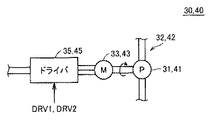
図2は、送出機構30および40のより詳細な概略構成図である。
図2を参照して、送出機構30は、送出ポンプ31と、ポンプ駆動電動機33と、ドライバ35とからなる。
FIG. 2 is a more detailed schematic configuration diagram of the
With reference to FIG. 2, the
送出ポンプ31は、ポンプ駆動電動機33と機械的に結合され、ポンプ駆動電動機33の回転駆動力により一方のポートから受けた電動機冷却油に圧力を与えて、他方のポートから送出する。一例として、送出ポンプ31は、インペラおよびベーンなどがポンプ駆動電動機33により回転されることで圧力を発生する。 The delivery pump 31 is mechanically coupled to the pump drive motor 33, applies pressure to the motor cooling oil received from one port by the rotational drive force of the pump drive motor 33, and sends it from the other port. As an example, the delivery pump 31 generates pressure when an impeller, a vane, and the like are rotated by a pump drive motor 33.
ポンプ駆動電動機33は、制御装置50からの指令DRV1に従い、ドライバ35から供給される電力を受けて回転する。一例として、ポンプ駆動電動機33は、DCセンサレスブラシレスモータである。
The pump drive motor 33 rotates in response to power supplied from the driver 35 in accordance with a command DRV1 from the
ドライバ35は、蓄電部16(図1)から受けた直流電力を所定の電圧に変換して、ポンプ駆動電動機33へ供給する。 The driver 35 converts the DC power received from the power storage unit 16 (FIG. 1) into a predetermined voltage and supplies it to the pump drive motor 33.
また、送出機構40は、送出機構30と略同一の構成で実現され、送出機構30において、送出ポンプ31、ポンプ駆動電動機33およびドライバ35に代えて、送出ポンプ41、ポンプ駆動電動機43およびドライバ45を配置し、かつ、指令DRV1に代えて指令DRV2を用いる構成と同様であるので、詳細な説明は繰返さない。
The
上述したように、この発明の実施の形態に従うハイブリッド車両100においては、電動機6の冷却機構(電動機ラジエタ34、送出機構30および冷却油循環経路32)と、PCU8の冷却機構(PCUラジエタ44、送出機構40および冷却水循環経路42)とは互いに独立に構成される。そのため、ハイブリッド車両100によれば、発生する車両駆動力(消費する電力)が大きくなるほど発熱量の増加する電動機6に対する冷却要求と、電動機6へ供給する電力にかかわらず発熱量が変化しないPCU8に対する冷却要求とをそれぞれ効率的に満足させることができる。
As described above, in
これに対して、電動機6およびPCU8を同一の冷却機構で冷却する構成においては、走行状況に応じて発熱量が変動する電動機6を十分冷却できるように、冷却能力を決定する必要がある。このように決定された冷却能力は、発熱量がほぼ同一のPCU8にとって過剰な冷却能力となることが多い。すなわち、電動機6およびPCU8が要求する冷却要求は互いに一致しないので、電動機6の冷却要求に合わせて過剰な冷却性能を発揮するように構成せざるを得なかった。その結果、ラジエタ、送出機構および循環経路が大型化するという問題があった。
On the other hand, in the configuration in which the
そこで、この発明の実施の形態に従うハイブリッド車両100においては、電動機6およびPCU8の冷却機構が独立に構成されるので、それぞれの発熱量に応じて適切に設計することができ、ラジエタ、送出機構および循環経路の大きさなどを効率化できる。
Therefore, in
以下、それぞれ電動機6およびPCU8の冷却機構における特徴的な構成について詳述する。
Hereinafter, characteristic configurations of the cooling mechanisms of the
(電動機6に対する冷却)
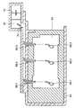
図3は、電動機6の冷却機構の一部である電動機冷却油の経路を示す部分断面図である。
(Cooling of the electric motor 6)
FIG. 3 is a partial cross-sectional view showing a path of electric motor cooling oil that is a part of the cooling mechanism of the
図3を参照して、電動機6を収納する収容室と減速ギアおよび車輪軸12を収容する各ケースの部分断面が示されている。
Referring to FIG. 3, a partial cross-section of a housing chamber that houses
図4は、図3のIV−IVにおける部分断面図である。
図3および図4を参照して、電動機6は隔壁60により形成された収容室に配置される。そして、隔壁60の上部には、電動機冷却油の通路64が設けられ、この通路64は、オイル溜り70および電動機6の収容室と連通している。
FIG. 4 is a partial cross-sectional view taken along the line IV-IV in FIG.
With reference to FIG. 3 and FIG. 4, the
電動機冷却油は、オイルレベルOLまで貯蔵されている。したがって、この収容室の底部はオイルパンとして機能する。そして、駆動軸10と機械的に連結された電動機6のロータ63の回転などに伴い、カウンタドリブンギア78が回転され、カウンタドリブンギア78の回転に伴い車輪軸12と機械的に連結されたディファレンシャルギア76が回転する。すると、図3の矢印に示すように、ディファレンシャルギア76が電動機冷却油を跳ね上げる。ケースの上部にはオイルキャッチ板72が設けられおり、ディファレンシャルギア76により跳ね上げられた電動機冷却油は、オイルキャッチ板72を通じてオイル溜り70に溜められる。オイル溜り70にはオイル出口74が設けられており、図4に示すように、オイル出口74は、オイル入口66.1,66.2,66.3と通じている。
The motor cooling oil is stored up to the oil level OL. Therefore, the bottom of the storage chamber functions as an oil pan. The counter driven
そして、通路64に到達した電動機冷却油は、隔壁60に設けられたオイル出口68.1,68.2,68.3を通りステータコイル62の上部に注がれる。ステータコイル62の上部に注がれた電動機冷却油は、ステータコイル62と熱交換をしながらその外周面を流動し、収容室の底部に戻される。すなわち、電動機冷却油は、ステータコイル62と直接接触してステータコイル62を冷却する。
Then, the motor cooling oil that has reached the
さらに、収容室の底部には、冷却油循環経路32と通じるための開口部が2箇所設けられており、貯蔵される電動機冷却油の一部が電動機ラジエタ34と間で循環されて電動機6の冷却が行なわれる。一例として、電動機6の直下に位置する開口部から電動機6の熱を吸収した比較的高温の電動機冷却油が抽出され、電動機ラジエタ34により冷却された後の電動機冷却油がディファレンシャルギア76の底部付近から戻される。
Furthermore, two openings for communicating with the cooling
このように、電動機6の上部から電動機冷却油をステータコイル62を注いで直接接触させるので、電動機6の発熱源であるステータコイル62を効率的に冷却することができる。そのため、電動機6により発生される車両駆動力が大きく、発熱量が多い場合であっても、電動機6を安定して冷却することができる。
Thus, since the
(PCU8に対する冷却)
再度、図1を参照して、電動機6およびPCU8の冷却機構が互いに独立に構成されるため、PCUラジエタ44の小型化などを実現できる一方で、PCUラジエタ44の小型化に伴い通水抵抗が増大する。この結果、送出機構40における消費電力が相対的に増加する。そこで、制御装置50は、PCU冷却水がPCU8とPCUラジエタ44との間で循環させる時間を短縮することにより、送出機構40における消費電力を抑制する。具体的には、制御装置50は、PCU8から出力されるPCU冷却水の温度が所定値以上であれば、切換弁46へ制御指令を与えて、PCU冷却水をPCUラジエタ44へ導いて冷却を行なう一方、PCU8から出力されるPCU冷却水の温度が所定値未満であれば、切換弁46へ制御指令を与えて、PCU冷却水をPCU8とバイパス経路48との間で循環させる。
(Cooling to PCU8)
Referring again to FIG. 1, since the cooling mechanisms of the
図5は、PCU8の冷却機構におけるPCU冷却水の経路を示す概略図である。
図5(a)は、PCU冷却水の温度が所定値以上である場合を示す。
FIG. 5 is a schematic view showing a path of PCU cooling water in the cooling mechanism of the
FIG. 5A shows a case where the temperature of the PCU cooling water is equal to or higher than a predetermined value.
図5(b)は、PCU冷却水の温度が所定値未満である場合を示す。
図5(a)を参照して、PCU冷却水の温度が所定値以上である場合には、制御装置50は、切換弁46がPCUラジエタ44側を選択するように制御指令を与える。すると、PCU冷却水は、PCU8とPCUラジエタ44との間を循環する。そのため、PCU8の熱を吸収(PCU8を冷却)したPCU冷却水は、PCUラジエタ44で熱交換されて冷却される。
FIG.5 (b) shows the case where the temperature of PCU cooling water is less than predetermined value.
Referring to FIG. 5 (a), when the temperature of the PCU cooling water is equal to or higher than a predetermined value,
一方、図5(b)を参照して、PCU冷却水の温度が所定値未満である場合には、制御装置50は、切換弁46がバイパス経路48を選択するように制御指令を与える。すると、PCU冷却水は、PCU8とバイパス経路48との間を循環する。そのため、PCU8の熱を吸収(PCU8を冷却)したPCU冷却水は、冷却されないままPCU8の熱を再度吸収する。したがって、PCU冷却水は、PCU8とバイパス経路48との間を繰返し循環することによって、温度が徐々に高まっていく。
On the other hand, referring to FIG. 5B, when the temperature of the PCU cooling water is less than a predetermined value,
このように、制御装置50は、PCU冷却水の温度が所定値以上となった場合にのみPCUラジエタ44にPCU冷却水を流し、それ以外の期間においてはPCUラジエタ44にPCU冷却水が流れないようにPCU冷却水をPCU8との間で循環させることで、送出機構40(ポンプ駆動電動機33)における消費電力を抑制する。
As described above, the
以下、制御装置50で実行されるプログラムの制御構造について説明する。
図6は、制御装置50で実行されるプログラムの制御構造を示すフローチャートである。制御装置50は、図6に示すフローチャートを所定周期(たとえば100msec)で繰返し実行する。
Hereinafter, a control structure of a program executed by the
FIG. 6 is a flowchart showing a control structure of a program executed by the
図6を参照して、制御装置50は、温度検出部52からPCU冷却水の温度を取得する(ステップS100)。そして、制御装置50は、PCU冷却水の温度が所定値以上であるか否かを判断する(ステップS102)。
Referring to FIG. 6,
PCU冷却水の温度が所定値以上である場合(ステップS102においてYESの場合)には、制御装置50は、PCUラジエタ44側を選択するように切換弁46に制御指令を与える(ステップS104)。
When the temperature of the PCU cooling water is equal to or higher than a predetermined value (YES in step S102),
PCU冷却水の温度が所定値未満である場合(ステップS102においてNOの場合)には、制御装置50は、バイパス経路48を選択するように切換弁46に制御指令を与える(ステップS106)。
When the temperature of the PCU cooling water is lower than the predetermined value (NO in step S102),
以下、制御装置50は、最初の処理に戻る。
この発明の実施の形態においては、電動機ラジエタ34、送出機構30および冷却油循環経路32が「第1の冷却機構」に相当し、冷却油循環経路32が「第1の循環経路」に相当し、電動機ラジエタ34が「第1の熱交換部」に相当し、送出機構30が「第1の送出機構」に相当する。また、PCUラジエタ44、送出機構40、冷却水循環経路42、バイパス経路48および切換弁46が「第2の冷却機構」に相当し、冷却水循環経路42が「第2の循環経路」に相当し、PCUラジエタ44が「第2の熱交換部」に相当し、送出機構40が「第2の送出機構」に相当し、切換弁46が「経路切換部」に相当する。さらに、制御装置50が「制御部」に相当する。
Hereinafter, the
In the embodiment of the present invention, the
なお、上述のこの発明の実施の形態においては、冷却媒体である電動機冷却油およびPCU冷却水の温度などの状態に応じて、ポンプ駆動電動機33および43の駆動タイミングや速度をさらに制御するように構成してもよい。このような構成によると、より効率的に電動機およびPCUを冷却できる。 In the above-described embodiment of the present invention, the drive timing and speed of the pump drive motors 33 and 43 are further controlled in accordance with the state of the motor cooling oil and the PCU cooling water as the cooling medium. It may be configured. According to such a configuration, the electric motor and the PCU can be cooled more efficiently.
また、上述のこの発明の実施の形態においては、電動機6を冷却する構成について詳述したが、電動機6の冷却構成と同様の構成により、発電機7を冷却するように構成してもよい。
Further, in the above-described embodiment of the present invention, the configuration for cooling the
また、上述のこの発明の実施の形態においては、本発明をパラレル/シリーズ式ハイブリッド車両に適用した場合の一例について説明したが、パラレル式ハイブリッド車両にも適用できることは言うまでもない。すなわち、図1において、図示しない他方の車輪を駆動するための電動機をさらに備えるようなパラレル/シリーズ式ハイブリッド車両に対しても本発明は適用可能である。 In the above-described embodiment of the present invention, an example in which the present invention is applied to a parallel / series hybrid vehicle has been described, but it goes without saying that the present invention can also be applied to a parallel hybrid vehicle. That is, in FIG. 1, the present invention can be applied to a parallel / series hybrid vehicle that further includes an electric motor for driving the other wheel (not shown).
この発明の実施の形態によれば、電動機6を冷却する冷却機構と、PCU8を冷却する冷却機構とを備えており、かつそれぞれの冷却機構は、蓄電部16から受けた電力により作動(冷却媒体の送出)を行なう。これにより、エンジン停止中であってもそれぞれの冷却機構により冷却媒体である電動機冷却油およびPCU冷却水が循環されて、電動機6およびPCU8を継続的に冷却できる。したがって、エンジンが間欠的に停止されるハイブリッド車両においても電動機および電力変換部を安定して冷却できる。
According to the embodiment of the present invention, the cooling mechanism for cooling the
また、この発明の実施の形態によれば、電動機6を冷却する冷却機構と、PCU8を冷却する冷却機構とは独立に配置されるので、それぞれの発熱量に応じて、ラジエタ、送出機構および循環経路などを適切に設計することができる。これにより、電動機6およびPCU8を共通の冷却機構で実現する場合のように、ラジエタ、送出機構および循環経路などを大型化して、過剰な冷却性能を発揮するように構成する必要がない。このため、各ポンプの総吐出量も抑制できるため、ポンプ駆動電動機33および43が消費する電力を低減できる。また、小型化された電動機ラジエタ34からの放熱量が低減されるので、電動機ラジエタ34を通過後の気流の温度上昇が抑制される。このため、その後方側に配置されるエンジンラジエタ20の雰囲気温度も低減されるので、エンジンラジエタ20の放熱効率を高めることができ、エンジンラジエタ20についてもより小型化することができる。
Further, according to the embodiment of the present invention, the cooling mechanism that cools the
さらに、この発明の実施の形態によれば、電動機6のステータコイル62の上部に電動機冷却油を注ぎ、当該電動機冷却油がステータコイル62の外周面を直接接触しながら流動することで、電動機6を冷却する。これにより、電動機6の発熱源であるステータコイル62を効率的に冷却できるため、急加速時や登坂走行時などの高負荷運転時において、電動機6の発熱量が多い場合であっても、電動機6を安定して冷却することができる。
Furthermore, according to the embodiment of the present invention, the electric motor cooling oil is poured onto the upper portion of the
さらに、この発明の実施の形態によれば、PCU冷却水の温度に応じて、PCU8およびPCUラジエタ44を含む経路、またはPCU8を含み、かつPCUラジエタ44を含まない経路を選択して、PCU冷却水を循環させることができる。これにより、PCUラジエタ44の小型化に伴って通水抵抗が増大し、送出機構40(実質的には、ポンプ駆動電動機43)における消費が増大する場合であっても、PCU冷却水をPCU8およびPCUラジエタ44を含む経路で循環させる時間比率を抑制できるので、総合的な消費電力を抑制できる。また、PCU冷却水をPCU8およびバイパス経路48を含む経路で循環させる期間においては、PCU8と接するPCU冷却水の流速を高めることで、PCU8に対する冷却効率を向上できる。すなわち、通水抵抗の増大に伴う消費電力の増加を抑制しつつ、PCU8に対する冷却効率の向上を同時に実現できる。
Further, according to the embodiment of the present invention, a
さらに、この発明の実施の形態によれば、電動機6の冷却に対して、油からなる冷却媒体(電動機冷却油)を用いることにより、絶縁性の低下および腐食を防止しつつ、電動機6のステータ上部に直接冷却媒体を注ぐことができる。そのため、電動機6の効率的な冷却を実現できる。一方、PCU8の冷却に対して、水からなる冷却媒体(PCU冷却水)を用いることにより、PCU8の温度上昇をPCU冷却水の沸点までに制限できる。
Furthermore, according to the embodiment of the present invention, a cooling medium (motor cooling oil) made of oil is used for cooling the
今回開示された実施の形態はすべての点で例示であって制限的なものではないと考えられるべきである。本発明の範囲は、上記した説明ではなく、特許請求の範囲によって示され、特許請求の範囲と均等の意味および範囲内でのすべての変更が含まれることが意図される。 The embodiment disclosed this time should be considered as illustrative in all points and not restrictive. The scope of the present invention is defined by the terms of the claims, rather than the description above, and is intended to include any modifications within the scope and meaning equivalent to the terms of the claims.
1 トランスアクスル、2 エンジン、4 動力伝達機構、6 電動機、7 発電機、8 PCU(パワーコントロールユニット)、10 駆動軸、12 車輪軸、14 駆動輪、16 蓄電部、20 エンジンラジエタ、22 冷却水循環経路、24 ラジエタファン、30,40 送出機構、31,41 送出ポンプ、32 冷却油循環経路、33,43 ポンプ駆動電動機、34 電動機ラジエタ、35,45 ドライバ、42 冷却水循環経路、44 PCUラジエタ、46 切換弁、48 バイパス経路、50 制御装置、52 温度検出部、60 隔壁、62 ステータコイル、63 ロータ、64 通路、66 オイル入口、68,74 オイル出口、72 オイルキャッチ板、76 ディファレンシャルギア、78 カウンタドリブンギア、100 ハイブリッド車両、DRV1,DRV2 指令、OL オイルレベル。 1 transaxle, 2 engine, 4 power transmission mechanism, 6 electric motor, 7 generator, 8 PCU (power control unit), 10 drive shaft, 12 wheel shaft, 14 drive wheel, 16 power storage unit, 20 engine radiator, 22 cooling water circulation Path, 24 radiator fan, 30, 40 delivery mechanism, 31, 41 delivery pump, 32 cooling oil circulation path, 33, 43 pump drive motor, 34 motor radiator, 35, 45 driver, 42 cooling water circulation path, 44 PCU radiator, 46 Switching valve, 48 Bypass path, 50 Control device, 52 Temperature detector, 60 Bulkhead, 62 Stator coil, 63 Rotor, 64 Passage, 66 Oil inlet, 68, 74 Oil outlet, 72 Oil catch plate, 76 Differential gear, 78 Counter Driven gear, 100 Hybrid vehicle, DRV1, DRV2 command, OL oil level.
Claims (3)
充放電可能に構成された蓄電部と、
前記蓄電部から受けた電力を前記電動機を駆動するために変換する電力変換部と、
第1の冷却媒体を介して前記電動機を冷却する第1の冷却機構と、
第2の冷却媒体を介して前記電力変換部を冷却する第2の冷却機構とを備え、
前記第1の冷却機構は、
前記第1の冷却媒体を熱交換して冷却する第1の熱交換部と、
前記電動機および前記第1の熱交換部を含んで形成される第1の循環経路に前記第1の冷却媒体を循環させるための第1の送出機構とを含み、
前記第2の冷却機構は、
前記第2の冷却媒体を熱交換して冷却する第2の熱交換部と、
前記電力変換部および前記第2の熱交換部を含んで形成される第2の循環経路に前記第2の冷却媒体を流動させる第2の送出機構と、
両端が前記第2の循環経路と接続され、前記電力変換部を含み、かつ前記第2の熱交換部を含まない経路に前記第2の冷却媒体を循環可能なように形成されたバイパス経路と、
前記電力変換部から出力された前記第2の冷却媒体が前記第2の熱交換部および前記バイパス経路のいずれか一方を流れるように切換え可能に構成された経路切換部と、
前記第2の冷却媒体の温度に基づいて前記経路切換部を制御する制御部とを含み、
前記エンジンは、走行状況に応じて間欠的に停止し、
前記第1および第2の送出機構は、電気的に作動することで前記エンジン停止中であっても作動可能に構成され、
前記電動機は、水平方向に回転軸を有するロータと、前記ロータの外周に配置されるステータコイルとを含み、
前記第1の冷却機構は、前記第1の冷却媒体を前記ステータコイルの重力上方位置より注ぐことで、前記ステータコイルに前記第1の冷却媒体を直接接触させて冷却する経路を含んで構成され、
前記制御部は、
前記第2の冷却媒体の温度が所定値以上であるときに、前記電力変換部および前記第2の熱交換部を含む経路に前記第2の冷却媒体を循環させるように前記経路切換部を制御し、
前記第2の冷却媒体の温度が所定値以上でないときに、前記バイパス経路に前記第2の冷却媒体を循環させるように前記経路切換部を制御するとともに、前記第2の冷却媒体が、前記第2の冷却媒体の温度が所定値以上である場合に比較してより高い流速で循環するように前記第2の送出機構を制御する、ハイブリッド車両。 An engine and an electric motor each configured to generate vehicle driving force;
A power storage unit configured to be chargeable and dischargeable;
A power converter that converts electric power received from the power storage unit to drive the electric motor;
A first cooling mechanism that cools the electric motor via a first cooling medium;
A second cooling mechanism for cooling the power conversion unit via a second cooling medium,
The first cooling mechanism includes:
A first heat exchanging section for exchanging heat to cool the first cooling medium;
A first delivery mechanism for circulating the first cooling medium in a first circulation path formed including the electric motor and the first heat exchange unit;
The second cooling mechanism includes:
A second heat exchanging section for exchanging heat to cool the second cooling medium;
A second delivery mechanism for causing the second cooling medium to flow in a second circulation path formed including the power conversion unit and the second heat exchange unit ;
A bypass path that is connected to the second circulation path at both ends, includes the power conversion unit, and is configured to circulate the second cooling medium in a path that does not include the second heat exchange unit; ,
A path switching unit configured to be switchable so that the second cooling medium output from the power conversion unit flows through one of the second heat exchange unit and the bypass path;
A control unit for controlling the path switching unit based on the temperature of the second cooling medium ,
The engine stops intermittently according to the driving situation,
The first and second delivery mechanisms are configured to be operable even when the engine is stopped by being electrically operated ,
The electric motor includes a rotor having a rotating shaft in a horizontal direction, and a stator coil disposed on an outer periphery of the rotor,
The first cooling mechanism includes a path that cools the first cooling medium by directly contacting the stator coil by pouring the first cooling medium from a position above the gravity of the stator coil. And
The controller is
When the temperature of the second cooling medium is equal to or higher than a predetermined value, the path switching unit is controlled to circulate the second cooling medium through a path including the power conversion unit and the second heat exchange unit. And
When the temperature of the second cooling medium is not equal to or higher than a predetermined value, the path switching unit is controlled to circulate the second cooling medium in the bypass path, and the second cooling medium is A hybrid vehicle that controls the second delivery mechanism to circulate at a higher flow rate than when the temperature of the second cooling medium is equal to or higher than a predetermined value .
前記電動機の駆動軸と機械的に連結されたギアと、
前記ギアを収容するとともに、その内部に前記第1の熱交換部によって冷却された後の前記第1の冷却媒体を前記ギアの一部と接するレベルまで溜めることのできるケースと、
前記ギアの回転により跳ね上げられる前記第1の冷却媒体を前記通路に導くキャッチ板とをさらに備える、請求項1に記載のハイブリッド車両。 A passage communicating above the gravity of the stator coil;
A gear mechanically coupled to the drive shaft of the electric motor;
A case capable of storing the gear and storing the first cooling medium after being cooled by the first heat exchanging part in a level in contact with a part of the gear;
The hybrid vehicle according to claim 1, further comprising: a catch plate that guides the first cooling medium splashed up by the rotation of the gear to the passage.
前記第2の冷却媒体は、水からなる、請求項1または2に記載のハイブリッド車両。 Said first cooling medium, Ri Do from the oil,
It said second cooling medium is composed of water, a hybrid vehicle according to claim 1 or 2.
Priority Applications (6)
| Application Number | Priority Date | Filing Date | Title |
|---|---|---|---|
| JP2006072834A JP4497113B2 (en) | 2006-03-16 | 2006-03-16 | Hybrid vehicle |
| CN2006800538766A CN101400557B (en) | 2006-03-16 | 2006-11-14 | Hybrid vehicle |
| US12/224,177 US7823669B2 (en) | 2006-03-16 | 2006-11-14 | Hybrid vehicle |
| KR1020087025177A KR101013469B1 (en) | 2006-03-16 | 2006-11-14 | Hybrid vehicle |
| PCT/JP2006/323069 WO2007108166A1 (en) | 2006-03-16 | 2006-11-14 | Hybrid vehicle |
| EP06823470A EP1995143B1 (en) | 2006-03-16 | 2006-11-14 | Hybrid vehicle |
Applications Claiming Priority (1)
| Application Number | Priority Date | Filing Date | Title |
|---|---|---|---|
| JP2006072834A JP4497113B2 (en) | 2006-03-16 | 2006-03-16 | Hybrid vehicle |
Publications (2)
| Publication Number | Publication Date |
|---|---|
| JP2007245946A JP2007245946A (en) | 2007-09-27 |
| JP4497113B2 true JP4497113B2 (en) | 2010-07-07 |
Family
ID=38522204
Family Applications (1)
| Application Number | Title | Priority Date | Filing Date |
|---|---|---|---|
| JP2006072834A Expired - Fee Related JP4497113B2 (en) | 2006-03-16 | 2006-03-16 | Hybrid vehicle |
Country Status (6)
| Country | Link |
|---|---|
| US (1) | US7823669B2 (en) |
| EP (1) | EP1995143B1 (en) |
| JP (1) | JP4497113B2 (en) |
| KR (1) | KR101013469B1 (en) |
| CN (1) | CN101400557B (en) |
| WO (1) | WO2007108166A1 (en) |
Families Citing this family (37)
| Publication number | Priority date | Publication date | Assignee | Title |
|---|---|---|---|---|
| JP4492672B2 (en) * | 2007-10-31 | 2010-06-30 | トヨタ自動車株式会社 | Control device for hybrid system |
| US8556011B2 (en) * | 2007-11-01 | 2013-10-15 | GM Global Technology Operations LLC | Prediction strategy for thermal management and protection of power electronic hardware |
| JP5099431B2 (en) * | 2008-02-15 | 2012-12-19 | アイシン・エィ・ダブリュ株式会社 | Inverter unit |
| JP2010213434A (en) * | 2009-03-10 | 2010-09-24 | Toyota Motor Corp | Motor control device and cooling device |
| US20100230189A1 (en) * | 2009-03-13 | 2010-09-16 | Gm Global Technology Operrations, Inc. | Cooling system for a vehicle |
| JP4911206B2 (en) * | 2009-08-31 | 2012-04-04 | トヨタ自動車株式会社 | Vehicle control apparatus and control method |
| EP2308708B1 (en) * | 2009-09-16 | 2016-08-17 | swissauto powersport llc | Electric vehicle with range extension |
| US8662968B2 (en) * | 2010-04-30 | 2014-03-04 | GM Global Technology Operations LLC | Air-based hybrid battery thermal conditioning system |
| KR20120036134A (en) * | 2010-10-07 | 2012-04-17 | 현대자동차주식회사 | Cooling system for hybrid vehicle |
| US8742701B2 (en) | 2010-12-20 | 2014-06-03 | Cummins Inc. | System, method, and apparatus for integrated hybrid power system thermal management |
| JP2012139000A (en) * | 2010-12-24 | 2012-07-19 | Aisin Aw Co Ltd | Vehicle drive device |
| US9096207B2 (en) | 2010-12-31 | 2015-08-04 | Cummins Inc. | Hybrid vehicle powertrain cooling system |
| JP5760215B2 (en) * | 2011-01-24 | 2015-08-05 | 株式会社 神崎高級工機製作所 | Axle drive device for work vehicle |
| JP5261514B2 (en) * | 2011-02-10 | 2013-08-14 | トヨタ自動車株式会社 | Mounting structure of power control device |
| US9132725B2 (en) | 2011-05-09 | 2015-09-15 | Cummins Inc. | Vehicle and hybrid drive system |
| CN102297009A (en) * | 2011-07-22 | 2011-12-28 | 奇瑞汽车股份有限公司 | Hybrid vehicle-cooling system |
| US9475574B2 (en) | 2011-09-14 | 2016-10-25 | Borealis Technical Limited | Heat dissipation system for aircraft drive wheel drive assembly |
| JP5790394B2 (en) * | 2011-10-14 | 2015-10-07 | トヨタ自動車株式会社 | Electric car |
| CN103298636B (en) * | 2011-11-14 | 2014-07-09 | 本田技研工业株式会社 | Electric vehicle |
| EP2792563B1 (en) * | 2011-12-15 | 2020-11-18 | Toyota Jidosha Kabushiki Kaisha | Hybrid vehicle control apparatus |
| JP5758820B2 (en) * | 2012-02-22 | 2015-08-05 | トヨタ自動車株式会社 | Rotating electric machine cooling system |
| US8978803B2 (en) | 2012-06-11 | 2015-03-17 | GM Global Technology Operations LLC | Divided dual inlet housing for an air-based hybrid battery thermal conditioning system |
| US10460865B2 (en) | 2012-11-09 | 2019-10-29 | Ford Global Technologies, Llc | Inductor assembly |
| US9892842B2 (en) | 2013-03-15 | 2018-02-13 | Ford Global Technologies, Llc | Inductor assembly support structure |
| US9543069B2 (en) | 2012-11-09 | 2017-01-10 | Ford Global Technologies, Llc | Temperature regulation of an inductor assembly |
| US9581234B2 (en) | 2012-11-09 | 2017-02-28 | Ford Global Technologies, Llc | Liquid cooled power inductor |
| WO2014076314A2 (en) * | 2012-11-19 | 2014-05-22 | Castrol Limited | Apparatus and method |
| US9631872B2 (en) | 2013-02-04 | 2017-04-25 | GM Global Technology Operations LLC | Multi-circuited vehicular thermal management system and method |
| US9126581B2 (en) * | 2013-05-08 | 2015-09-08 | GM Global Technology Operations LLC | Hybrid powertrain and modular rear drive unit for same |
| DE102014103471A1 (en) * | 2014-03-14 | 2015-09-17 | Dr. Ing. H.C. F. Porsche Aktiengesellschaft | Electric actuator |
| US9828025B1 (en) * | 2014-08-28 | 2017-11-28 | Hydro-Gear Limited Partnership | Electric transaxle with integral power generating device |
| US10183694B1 (en) | 2014-08-28 | 2019-01-22 | Hydro-Gear Limited Partnership | Electric transaxle with integral power generating device |
| JP6394770B1 (en) * | 2017-08-30 | 2018-09-26 | トヨタ自動車株式会社 | vehicle |
| DE102018213990B3 (en) | 2018-08-20 | 2019-09-05 | Magna Pt B.V. & Co. Kg | hybrid transmission |
| CN109878325A (en) * | 2018-12-29 | 2019-06-14 | 北京新能源汽车技术创新中心有限公司 | Cooling system for electric vehicle, electric vehicle and method for controlling cooling system of electric automobile |
| JP7392592B2 (en) * | 2020-07-01 | 2023-12-06 | マツダ株式会社 | vehicle |
| DE102022103357B4 (en) | 2022-02-14 | 2023-10-05 | Dr. Ing. H.C. F. Porsche Aktiengesellschaft | motor vehicle |
Citations (12)
| Publication number | Priority date | Publication date | Assignee | Title |
|---|---|---|---|---|
| JPH04275492A (en) * | 1991-03-04 | 1992-10-01 | Toyota Motor Corp | Cooler for power conversion means of electric vehicle |
| JPH05310048A (en) * | 1992-05-01 | 1993-11-22 | Aqueous Res:Kk | Driving device for vehicle |
| JPH08130856A (en) * | 1994-10-31 | 1996-05-21 | Aisin Aw Co Ltd | Cooling circuit for motor |
| JPH08196002A (en) * | 1995-01-12 | 1996-07-30 | Nissan Motor Co Ltd | Cooler for electric vehicle |
| JPH10238345A (en) * | 1997-02-25 | 1998-09-08 | Nissan Motor Co Ltd | Cooling device for hybrid electric automobile |
| JPH11511224A (en) * | 1995-08-31 | 1999-09-28 | イーエスアーデー・エレクトロニク・ジステームス・ゲーエムベーハー・ウント・コンパニ・カーゲー | Drive system, in particular for motor vehicles, and a method for operating this drive system |
| JPH11285106A (en) * | 1998-03-26 | 1999-10-15 | Nissan Motor Co Ltd | Cooler of hybrid vehicle |
| JP2003169448A (en) * | 2001-12-03 | 2003-06-13 | Nissan Motor Co Ltd | Driver for hybrid vehicle |
| JP2004048987A (en) * | 2002-06-17 | 2004-02-12 | Ford Motor Co | Method for controlling hybrid electric vehicle |
| JP2004100956A (en) * | 2002-09-06 | 2004-04-02 | Ford Global Technologies Llc | Cooling system and method for hybrid electric vehicle |
| JP2004112855A (en) * | 2002-09-13 | 2004-04-08 | Nissan Motor Co Ltd | Controller for vehicle |
| JP2005117790A (en) * | 2003-10-08 | 2005-04-28 | Toyota Motor Corp | Driver and automobile carrying the same |
Family Cites Families (6)
| Publication number | Priority date | Publication date | Assignee | Title |
|---|---|---|---|---|
| DE4327261C1 (en) * | 1993-08-13 | 1994-10-13 | Daimler Benz Ag | Coolant circuit |
| DE4433836C1 (en) * | 1994-09-22 | 1995-11-09 | Daimler Benz Ag | Device for heating an interior of an electric vehicle |
| US6450275B1 (en) * | 2000-11-02 | 2002-09-17 | Ford Motor Company | Power electronics cooling for a hybrid electric vehicle |
| CN100410095C (en) * | 2004-06-10 | 2008-08-13 | 株式会社电装 | Cooling system used for hybrid-powered automobile |
| DE102005047653B4 (en) * | 2005-10-05 | 2021-08-19 | Volkswagen Ag | Hybrid drive unit with low temperature circuit |
| US7377237B2 (en) * | 2006-09-13 | 2008-05-27 | Cummins Power Generation Inc. | Cooling system for hybrid power system |
-
2006
- 2006-03-16 JP JP2006072834A patent/JP4497113B2/en not_active Expired - Fee Related
- 2006-11-14 US US12/224,177 patent/US7823669B2/en active Active
- 2006-11-14 CN CN2006800538766A patent/CN101400557B/en not_active Expired - Fee Related
- 2006-11-14 KR KR1020087025177A patent/KR101013469B1/en not_active IP Right Cessation
- 2006-11-14 WO PCT/JP2006/323069 patent/WO2007108166A1/en active Application Filing
- 2006-11-14 EP EP06823470A patent/EP1995143B1/en not_active Expired - Fee Related
Patent Citations (12)
| Publication number | Priority date | Publication date | Assignee | Title |
|---|---|---|---|---|
| JPH04275492A (en) * | 1991-03-04 | 1992-10-01 | Toyota Motor Corp | Cooler for power conversion means of electric vehicle |
| JPH05310048A (en) * | 1992-05-01 | 1993-11-22 | Aqueous Res:Kk | Driving device for vehicle |
| JPH08130856A (en) * | 1994-10-31 | 1996-05-21 | Aisin Aw Co Ltd | Cooling circuit for motor |
| JPH08196002A (en) * | 1995-01-12 | 1996-07-30 | Nissan Motor Co Ltd | Cooler for electric vehicle |
| JPH11511224A (en) * | 1995-08-31 | 1999-09-28 | イーエスアーデー・エレクトロニク・ジステームス・ゲーエムベーハー・ウント・コンパニ・カーゲー | Drive system, in particular for motor vehicles, and a method for operating this drive system |
| JPH10238345A (en) * | 1997-02-25 | 1998-09-08 | Nissan Motor Co Ltd | Cooling device for hybrid electric automobile |
| JPH11285106A (en) * | 1998-03-26 | 1999-10-15 | Nissan Motor Co Ltd | Cooler of hybrid vehicle |
| JP2003169448A (en) * | 2001-12-03 | 2003-06-13 | Nissan Motor Co Ltd | Driver for hybrid vehicle |
| JP2004048987A (en) * | 2002-06-17 | 2004-02-12 | Ford Motor Co | Method for controlling hybrid electric vehicle |
| JP2004100956A (en) * | 2002-09-06 | 2004-04-02 | Ford Global Technologies Llc | Cooling system and method for hybrid electric vehicle |
| JP2004112855A (en) * | 2002-09-13 | 2004-04-08 | Nissan Motor Co Ltd | Controller for vehicle |
| JP2005117790A (en) * | 2003-10-08 | 2005-04-28 | Toyota Motor Corp | Driver and automobile carrying the same |
Also Published As
| Publication number | Publication date |
|---|---|
| KR20080109851A (en) | 2008-12-17 |
| KR101013469B1 (en) | 2011-02-14 |
| CN101400557B (en) | 2012-02-22 |
| CN101400557A (en) | 2009-04-01 |
| EP1995143A4 (en) | 2011-05-04 |
| JP2007245946A (en) | 2007-09-27 |
| US20090195093A1 (en) | 2009-08-06 |
| WO2007108166A1 (en) | 2007-09-27 |
| EP1995143B1 (en) | 2012-04-18 |
| EP1995143A1 (en) | 2008-11-26 |
| US7823669B2 (en) | 2010-11-02 |
Similar Documents
| Publication | Publication Date | Title |
|---|---|---|
| JP4497113B2 (en) | Hybrid vehicle | |
| EP3517335B1 (en) | Electric vehicle | |
| JP5257220B2 (en) | Battery system | |
| JP5433387B2 (en) | Vehicle equipment cooling and heating system | |
| JP4888558B2 (en) | Cooling structure of rotating electric machine | |
| JP5331666B2 (en) | Electric vehicle cooling system | |
| JP5497716B2 (en) | Vehicle charging device | |
| WO2008041761A1 (en) | Vehicle drive device | |
| WO2008032837A1 (en) | Drive device for vehicle | |
| WO2007049799A1 (en) | Drive device of vehicle | |
| JP2011125121A (en) | Warm-up control of motor | |
| GB2509308A (en) | Heat transfer arrangement for heating battery | |
| JP2009292319A (en) | Cooling device | |
| JP2013193511A (en) | Vehicle control system | |
| JP6705341B2 (en) | Hybrid car | |
| JP5985844B2 (en) | Vehicle control system | |
| JP2009040320A (en) | Cooling system | |
| JP2007131235A (en) | Drive device for hybrid vehicle | |
| JP2005113831A (en) | Cooling system for hybrid vehicle | |
| JP7035559B2 (en) | Electric vehicle | |
| JP2009040321A (en) | Cooling structure of drive device for vehicle, and vehicle | |
| JP5228545B2 (en) | Superconducting motor device and electric vehicle | |
| JP2013236525A (en) | Cooling controller | |
| JP2008260374A (en) | Cooling device of electric equipment mounted on vehicle | |
| JP5876290B2 (en) | Vehicle control system |
Legal Events
| Date | Code | Title | Description |
|---|---|---|---|
| A621 | Written request for application examination |
Free format text: JAPANESE INTERMEDIATE CODE: A621 Effective date: 20080616 |
|
| A131 | Notification of reasons for refusal |
Free format text: JAPANESE INTERMEDIATE CODE: A131 Effective date: 20081209 |
|
| A521 | Request for written amendment filed |
Free format text: JAPANESE INTERMEDIATE CODE: A523 Effective date: 20090205 |
|
| A02 | Decision of refusal |
Free format text: JAPANESE INTERMEDIATE CODE: A02 Effective date: 20091020 |
|
| A521 | Request for written amendment filed |
Free format text: JAPANESE INTERMEDIATE CODE: A523 Effective date: 20100120 |
|
| A911 | Transfer to examiner for re-examination before appeal (zenchi) |
Free format text: JAPANESE INTERMEDIATE CODE: A911 Effective date: 20100129 |
|
| TRDD | Decision of grant or rejection written | ||
| A01 | Written decision to grant a patent or to grant a registration (utility model) |
Free format text: JAPANESE INTERMEDIATE CODE: A01 Effective date: 20100323 |
|
| A01 | Written decision to grant a patent or to grant a registration (utility model) |
Free format text: JAPANESE INTERMEDIATE CODE: A01 |
|
| A61 | First payment of annual fees (during grant procedure) |
Free format text: JAPANESE INTERMEDIATE CODE: A61 Effective date: 20100405 |
|
| FPAY | Renewal fee payment (event date is renewal date of database) |
Free format text: PAYMENT UNTIL: 20130423 Year of fee payment: 3 |
|
| R151 | Written notification of patent or utility model registration |
Ref document number: 4497113 Country of ref document: JP Free format text: JAPANESE INTERMEDIATE CODE: R151 |
|
| FPAY | Renewal fee payment (event date is renewal date of database) |
Free format text: PAYMENT UNTIL: 20130423 Year of fee payment: 3 |
|
| LAPS | Cancellation because of no payment of annual fees |