JP4489609B2 - Liquid mixing device - Google Patents
Liquid mixing device Download PDFInfo
- Publication number
- JP4489609B2 JP4489609B2 JP2005020047A JP2005020047A JP4489609B2 JP 4489609 B2 JP4489609 B2 JP 4489609B2 JP 2005020047 A JP2005020047 A JP 2005020047A JP 2005020047 A JP2005020047 A JP 2005020047A JP 4489609 B2 JP4489609 B2 JP 4489609B2
- Authority
- JP
- Japan
- Prior art keywords
- liquid
- chamber
- liquid separation
- generating means
- mixing chamber
- Prior art date
- Legal status (The legal status is an assumption and is not a legal conclusion. Google has not performed a legal analysis and makes no representation as to the accuracy of the status listed.)
- Active
Links
Images


Description
この発明は、密閉された装置内において、種類の異なる所定量の液体同士を混合するために使用される液体混合装置に関するものである。 The present invention relates to a liquid mixing device used for mixing predetermined amounts of different kinds of liquids in a sealed device.
従来から、種々ある検査方法の一つとして、例えば、綿棒、綿球や吸湿性スポンジ等が先端に取り付けられた検体採取具で採取された検体(人体の鼻や喉等の粘膜や食器等への付着物など)を希釈液に浸漬し、検体を希釈液内に回収して検液とし、この検液を所定量だけピペットで吸い上げて反応液や処理液に分注するようなものがある。 Conventionally, as one of various testing methods, for example, a sample collected with a sample collecting tool attached to the tip of a cotton swab, cotton ball, hygroscopic sponge, etc. (to a mucous membrane such as a human nose or throat, tableware, etc.) Some specimens are soaked in a diluent, collected in the diluent, used as a test solution, and a predetermined amount of this test solution is drawn up with a pipette and dispensed into the reaction solution or treatment solution. .
しかしながら、このような方法では、検液を正確に所定量だけ分注する必要がある場合には、ピペットによる作業では困難である。 However, with such a method, when it is necessary to accurately dispense a predetermined amount of the test solution, it is difficult to work with a pipette.
そこで、図13に示すような検査キット100が開発された(特許文献1参照)。この検査キット100は、透明な有底筒状容器101の上部開口部に着脱可能なキャップ102が係合されるようになっており、キャップ102に固定された綿棒103の先端の綿球103aが容器101の上部開口部をキャップ102で閉じた場合に容器101内の希釈液104に浸漬され、綿球103aに付着した検体が希釈液104内に回収されて検液となるように構成されている(図13(a)参照)。また、この検査キット100の透明な容器101の側壁には、容器101内の液体(希釈液104又は検液)を目視によって計量するための計量目盛り105が付けられている(図13(a)〜(b)参照)。そして、キャップ102には、容器101内と容器101の外部とを連通する分注用開口106と、この分注用開口106を開閉する蓋部材107が取り付けられている(図13(a)〜(b)参照)。
Therefore, an
このように形成された検査キット100は、容器101内の希釈液104に検体を回収して検液とした後(図13(a)参照)、キャップ102の蓋部材107を開き(図13(b)参照)、キャップ102の分注用開口106を大気開放した後、容器101を天地逆転し、計量目盛り105にしたがって所定量の検液を下側の分注用開口106から図外の液体混合容器内に滴下するようになっている(図13(c)参照)。なお、液体混合容器内には予め反応液又は処理液等が所定量収容されており、容器101から滴下された検液と反応液又は処理液等とが液体混合容器内で撹拌され混合されることになる。
The thus formed
特許文献1に開示された従来技術は、計量目盛りにしたがって検液を容易に分注することができる優れたものであるが、検液を分注する際に、検液を大気中に放出することになるため、大気中の浮遊物(ウイルスや微小タンパク質等)が検液に混入することを厳しく規制する必要がある場合や、検液中の検体等が大気中に飛散することを厳しく規制する必要がある場合に使用することができないという不具合を有している。
The prior art disclosed in
また、特許文献1に開示された従来技術は、図13(c)に示すように、容器101の後端を指先で押して変形させ、計量目盛り105を目視しながら容器101外部への検液の滴下量を調整するようになっているが、この調整作業が作業者の目視と勘によるものであるため、検液の滴下量にばらつきを生じやすいという問題を有していた。
Further, as shown in FIG. 13C, the conventional technique disclosed in
また、検液と反応液等との混合作業を大気開放状態で行う場合には、大気中の異物が容器内の液体に混入したり、また検体等が容器外部に飛散して環境汚染を招いたりする虞もあった。 In addition, when mixing the test solution with the reaction solution, etc. in an open atmosphere, foreign matter in the atmosphere is mixed into the liquid in the container, or the sample is scattered outside the container, causing environmental pollution. There was also a risk of going.
また、検液と反応液等との撹拌混合作業が大気開放状態で行われると、空気が液体に混ざり、撹拌されている液体に気泡が発生することがあるため、気泡消滅まで後工程を実行できず、作業時間のロスを生じやすいという問題を有していた。 In addition, if the stirring and mixing work of the test solution and reaction solution is performed in an open air state, air may be mixed with the liquid and bubbles may be generated in the stirred liquid. It was not possible, and there was a problem that loss of working time was likely to occur.
そこで、本発明は、上記従来技術の不具合を解消するため、検液等の液体の計量・混合作業等を密閉空間内で正確に且つ容易に行うことができるようにしている。 Therefore, in order to eliminate the above-described problems of the prior art, the present invention is capable of accurately and easily performing measurement and mixing operations of liquids such as test solutions in a sealed space.
請求項1の発明に係る液体分注装置は、密閉された貯留室内の第1の液体の一部を密閉された液体分離室内に移動させた後、前記液体分離室に逆流防止機構を介して接続されている密閉された分注準備室に前記液体分離室内の第1の液体の所定量を移動させる液体分離部と、前記分注準備室内の第1の液体を密閉された液体混合室内に導入し、前記液体混合室内に予め注入してある第2の液体に前記第1の液体を注入し且つ混合する液体混合部と、を備えている。この発明に係る液体分注装置は、前記貯留室と前記液体分離室とを大気開放されない第1連通路で接続し、前記分注準備室と前記液体混合室とを大気開放されない第2連通路で接続し、前記液体分離室には前記貯留室内の圧力よりも前記液体分離室内の圧力の方を低くすることができる第1差圧発生手段を配置し、前記液体混合室には前記分注準備室内の圧力よりも前記液体混合室内の圧力を低くすることができる第2差圧発生手段を配置し、前記液体混合室にはこの液体混合室からの液体の流出を可能にする液体混合室開閉手段を取り付けてある。そして、この発明の液体分注装置は、前記第1の液体の移動及び前記第1の液体と前記第2の液体の混合を大気と遮断した状態で行い、且つ、前記貯留室から前記液体分離室への第1の液体の移動、及び前記分注準備室から前記液体混合室への第1の液体の移動を圧力差で行うようにしたことを特徴としている。 In the liquid dispensing apparatus according to the first aspect of the present invention, after a part of the first liquid in the sealed storage chamber is moved into the sealed liquid separation chamber, the liquid separation chamber is connected to the liquid separation chamber via a backflow prevention mechanism. A liquid separation unit that moves a predetermined amount of the first liquid in the liquid separation chamber to a connected sealed dispensing preparation chamber, and the first liquid in the dispensing preparation chamber to the sealed liquid mixing chamber And a liquid mixing section for injecting and mixing the first liquid into the second liquid previously introduced into the liquid mixing chamber. In the liquid dispensing apparatus according to the present invention, the storage chamber and the liquid separation chamber are connected by a first communication path that is not opened to the atmosphere, and the dispensing preparation chamber and the liquid mixing chamber are not opened to the atmosphere. And a first differential pressure generating means capable of lowering the pressure in the liquid separation chamber than the pressure in the storage chamber is disposed in the liquid separation chamber, and the dispensing is provided in the liquid mixing chamber. A second differential pressure generating means capable of lowering the pressure in the liquid mixing chamber than the pressure in the preparation chamber is disposed, and the liquid mixing chamber enables the liquid to flow out from the liquid mixing chamber. Opening and closing means are attached. In the liquid dispensing apparatus of the present invention, the movement of the first liquid and the mixing of the first liquid and the second liquid are performed while being isolated from the atmosphere, and the liquid separation is performed from the storage chamber. The movement of the first liquid into the chamber and the movement of the first liquid from the dispensing preparation chamber into the liquid mixing chamber are performed by a pressure difference.
請求項2の発明は、請求項1の発明に係る液体分注装置において、前記液体分離室の上部に前記第1差圧発生手段をスライド可能に収容する第1作業空間を配置する一方、前記液体分離室の下部に分注準備室を配置するようになっている。そして、前記液体分離室と前記第1作業空間とを前記第1差圧発生手段のピストンで仕切り、前記液体分離室と前記分注準備室とを前記液体分離室からの液体の流出のみを許容する逆流防止機構で仕切り、前記第1作業空間と大気とを前記第1差圧発生手段のサブピストンで仕切るようになっている。また、前記第1作業空間のうちの前記ピストンとサブピストンとで仕切られる空間、前記貯留室の空間、及び前記分注準備室の空間を、大気と遮断された圧力調整路で大気と遮断された圧力調整室に接続するようになっている。この圧力調整室は、有底筒状の穴内にスライド可能に収容された圧力調整ピストンによって大気と遮断された前記穴の空間であって、前記圧力調整ピストンで仕切られる穴内の圧力と外気圧との圧力差によって前記圧力調整ピストンが移動することにより体積が増減するようになっている。そして、前記第1差圧発生手段の前記ピストンが前記液体分離室の下端から前記液体分離室の容積を増加させる方向に移動すると、前記液体分離室内の圧力が低下していき、前記ピストンが前記第1連通路の前記液体分離室側開口部を開く位置まで移動すると、前記貯留室内の圧力と前記液体分室内の圧力との差に基づいて前記貯留室内の第1の液体が前記第1連通路内を流動して前記液体分離室内に移動する。その後、前記ピストンを前記液体分離室の下端方向に向けて移動させると、余分な第1の液体が前記第1連通路を介して前記貯留室に戻り、前記液体分離室内の所定量の第1の液体が前記逆流防止機構を押し広げて前記分注準備室の空間に移動する。その後、前記第2差圧発生手段を作動させて前記液体混合室内の圧力を低下させると、前記分注準備室と前記液体混合室との圧力差に基づいて前記分流準備室内の所定量の第1の液体が前記第2連通路内を流動して前記液体混合室内に流入し、前記液体混合室内の前記第2の液体と前記第1の液体とが混合するようになっている。 According to a second aspect of the present invention, in the liquid dispensing apparatus according to the first aspect of the present invention, the first working space that slidably accommodates the first differential pressure generating means is disposed above the liquid separation chamber. A dispensing preparation chamber is arranged at the bottom of the liquid separation chamber. The liquid separation chamber and the first work space are partitioned by a piston of the first differential pressure generating means, and the liquid separation chamber and the dispensing preparation chamber are allowed to flow out only from the liquid separation chamber. The first working space and the atmosphere are partitioned by a sub-piston of the first differential pressure generating means. In addition, the space of the first working space that is partitioned by the piston and the sub-piston, the space of the storage chamber, and the space of the dispensing preparation chamber are blocked from the atmosphere by a pressure adjustment path that is blocked from the atmosphere. It is designed to be connected to the pressure adjustment chamber. The pressure adjusting chamber is a space of the hole that is blocked from the atmosphere by a pressure adjusting piston that is slidably accommodated in a bottomed cylindrical hole, and the pressure in the hole partitioned by the pressure adjusting piston and the external pressure The volume is increased or decreased as the pressure adjusting piston moves due to the pressure difference. Then, when the piston of the first differential pressure generating means moves in the direction of increasing the volume of the liquid separation chamber from the lower end of the liquid separation chamber, the pressure in the liquid separation chamber decreases, and the piston When the first separation passage moves to a position where the liquid separation chamber side opening is opened, the first liquid in the storage chamber is moved to the first communication based on the difference between the pressure in the storage chamber and the pressure in the liquid compartment. It flows in the passage and moves into the liquid separation chamber. Thereafter, when the piston is moved toward the lower end of the liquid separation chamber, excess first liquid returns to the storage chamber via the first communication path, and a predetermined amount of the first liquid in the liquid separation chamber. Liquid spreads the backflow prevention mechanism and moves to the space of the dispensing preparation chamber. Thereafter, when the second differential pressure generating means is operated to reduce the pressure in the liquid mixing chamber, a predetermined amount of the first in the diversion preparation chamber is determined based on the pressure difference between the dispensing preparation chamber and the liquid mixing chamber. One liquid flows through the second communication passage and flows into the liquid mixing chamber, so that the second liquid and the first liquid in the liquid mixing chamber are mixed.
請求項3の発明は、請求項1又は2の発明に係る液体分注装置において、前記液体混合室は断面形状がほぼ円形の筒状空間である。そして、前記第2連通路は、前記液体混合室の斜め上方から斜めに降下して前記液体混合室内に開口し、且つ、前記液体混合室の中心に対して偏心した状態で開口して、前記第1の液体の前記液体混合室内への流入状態を、前記第1の液体が前記液体混合室の壁面に沿って回動しながら下降する旋回流とするようになっている。 According to a third aspect of the invention, in the liquid dispensing apparatus according to the first or second aspect of the invention, the liquid mixing chamber is a cylindrical space having a substantially circular cross-sectional shape. The second communication path is obliquely lowered from above the liquid mixing chamber and opened in the liquid mixing chamber, and is opened in a state eccentric to the center of the liquid mixing chamber, The inflow state of the first liquid into the liquid mixing chamber is a swirling flow in which the first liquid descends while rotating along the wall surface of the liquid mixing chamber.
本発明によれば、第1の液体(例えば、検体が希釈液内に回収された検液)を所定量だけ分離する作業、及び分離した第1の液体を第2の液体(反応液や処理液等)に混合する作業を、大気と遮断された密閉空間内で行うことができる。 According to the present invention, the operation of separating a first liquid (for example, a test solution in which a specimen is collected in a diluent) by a predetermined amount, and the separated first liquid into a second liquid (reaction liquid or treatment). The operation of mixing with a liquid or the like can be performed in an enclosed space that is shielded from the atmosphere.
その結果、本発明によれば、検液に大気中の浮遊物が混入することがなく、正確に検体検査を行うことができる。 As a result, according to the present invention, the specimen test can be performed accurately without the suspended matter in the atmosphere being mixed into the test solution.
また、本発明によれば、検液が大気中に飛散するようなことがなく、人体に有害な検体の検査の安全性を確保できる。 In addition, according to the present invention, the test solution is not scattered in the atmosphere, and the safety of the test of a specimen harmful to the human body can be ensured.
また、本発明によれば、第1の液体と第2の液体が密閉され且つ圧力降下した液体混合室内で混合されるため、気泡の発生がなく、第1の液体と第2の液体の混合作業が短時間に終了する。 In addition, according to the present invention, since the first liquid and the second liquid are mixed and mixed in the liquid mixing chamber in which the pressure has dropped, there is no generation of bubbles, and the first liquid and the second liquid are mixed. Work is completed in a short time.
また、本発明によれば、液体分離室から分注準備室内に所定量の第1の液体が分離移動させられるため、目視による計量が不要になり、第1の液体の分離作業がばらつきなく正確に行われる。 Further, according to the present invention, since a predetermined amount of the first liquid is separated and moved from the liquid separation chamber to the dispensing preparation chamber, visual measurement is not necessary, and the separation operation of the first liquid is accurate and uniform. To be done.
以下、本発明の最良の実施形態を図面に基づき詳述する。 Hereinafter, the best embodiment of the present invention will be described in detail with reference to the drawings.
(液体分注装置全体の概略構造)
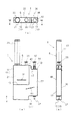
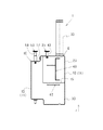
図1乃至図3は、本発明の液体分注装置1を模式的に示す図である。このうち、図1(a)は液体分注装置1の正面図、図1(b)は同右側面図、図1(c)は同平面図である。また、図2は、液体分注装置1の背面図である。また、図3は、液体分注装置1の縦断面図であり、図1(c)のA−A線に沿って切断して示す断面図である。
(Schematic structure of the entire liquid dispensing device)
1 to 3 are views schematically showing a
これらの図に示すように、液体分注装置1は、密閉された貯留室2内の第1の液体3の一部を密閉された液体分離室5内に移動させた後、液体分離室5の所定量の第1の液体3を逆流防止機構としての逆止弁40を介して分注準備室41内に移動させる液体分離部6と、分注準備室41内の第1の液体3を密閉された液体混合室7内に注入し、液体混合室7内に予め注入してある第2の液体8と第1の液体3とを混合する液体混合部10と、を備えている。そして、この液体分注装置1の装置本体11は、主に液体分離部6を配置する第1ブロック12と、主に液体混合部10を配置する第2ブロック13とに分割されている。このうち、第1ブロック12は、第2ブロック13の第1ブロック取付部15にねじ16,17で固定されるようになっている。ここで、液体分離部6は、第1連通路31,第1差圧発生手段取付穴36,第1差圧発生手段35,逆止弁40及び分注準備室41を備えている。また、液体混合部10は、第2連通路61,第2差圧発生手段取付穴52及び第2差圧発生手段53を備えている。
As shown in these drawings, the
第1ブロック12及び第2ブロック13は、図1(b)に示すように、厚さ寸法(図1の左右方向寸法)が略同一であり、しかもその厚さ寸法が貯留室2の外径寸法よりも僅かに大きくなる程度の寸法に決定されている(図5(b)参照)。また、第1ブロック12は、図1乃至図3に示すように、正面側の形状が略矩形形状であり、且つ、平面側の形状が細長い略矩形形状であって、全体としてシガレットケースのような直方体形状に形成されている。また、第2ブロック13に第1ブロック12を組み付けた状態の装置本体11の形状は、図1乃至図3に示すように、正面形状が上端部及び下端部に一部分切り欠きを有する略矩形形状を呈し、平面形状が細長い略矩形形状であって、全体として略直方体形状に形成されている。
As shown in FIG. 1B, the
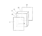
このうち、第1ブロック12は、図10に示すように、透明の合成樹脂材料で形成された第1ブロック本体18と、この第1ブロック本体18の正面側側面20のほぼ全面に貼り付けられる透明樹脂製の第1フィルム21と、第1ブロック本体18の背面側側面22のほぼ全面に貼り付けられる透明樹脂製の第2フィルム23と、を有している。また、第2ブロック13は、図11に示すように、透明の合成樹脂材料で形成された第2ブロック本体25と、この第2ブロック本体25の正面側側面26のほぼ全面に貼り付けられる透明樹脂製の第3フィルム27と、第2ブロック本体25の背面側側面28のほぼ全面に貼り付けられる透明樹脂製の第4フィルム30と、を有している。なお、本実施形態において、第1ブロック12及び第2ブロック13は、内部の第1の液体3及び第2の液体8の移動状態等が視認できるように、全体が透明樹脂材料で形成される態様を例示したが、これに限られず、全体を不透明な樹脂で形成してもよく、また、一部のみを透明樹脂材料で形成するようにしてもよい。また、第1ブロック本体18及び第2ブロック本体25の正面側側面20,26のほぼ全面を一枚の樹脂フィルムで覆うようにし、第1ブロック本体18及び第2ブロック本体25の背面側側面22,28のほぼ全面を一枚の樹脂フィルムで覆うようにしてもよい。さらに、後述する第1連通路31,第2連通路61,圧路力調整路48,62の開口部を覆うために、第1ブロック本体18及び第2ブロック本体25の正面側側面20,26及び背面側側面22,28に部分的に樹脂フィルムを貼り付けるようにしてもよい。
Among these, as shown in FIG. 10, the
(液体分注装置の第1ブロックの構成)
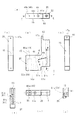
図4乃至図6は、第1ブロック本体18の詳細を示す図である。このうち、図4(a)〜(f)は、それぞれ順に、第1ブロック本体18の正面側側面図、右側側面図、左側側面図、平面図、底面図、図4(a)のB−B線に沿って切断して示す断面図、に対応している。また、図5(a)〜(d)は、それぞれ順に、第1ブロック本体18の背面図、C1−C1線に沿って切断して示す断面図、図5(b)の一部拡大断面図、図5(a)のC2−C2線に沿って切断して示す断面図、に対応している。また、図6(a)〜(b)は、それぞれ、順に、図4(d)のD−D線に沿って切断して示す断面図、図6(a)の一部拡大断面図である。
(Configuration of the first block of the liquid dispensing device)
4 to 6 are views showing details of the
これらの図に示すように、第1ブロック本体18には、希釈液が注入される貯留室2が形成されている。この貯留室2は、有底筒形形状に形成されており、上方に開口し、下端側に第1連通路31の一端が接続し、その下端側が第1連通路31を介して隣りの液体分離室5に連通するようになっている。そして、この貯留室2は、綿棒32を保持したキャップ33が上方の開口部に着脱可能に装着されるようになっており、キャップ33を開口部に装着した状態で開口部が塞がれ(大気と遮断され)、キャップ33を開口部から取り外した状態で開口部が大気開放されるようになっている(図1乃至図3参照)。なお、綿棒32は、先端に設けられている綿体部が貯留室2内に注入してある希釈液に浸漬されるようになっている。そして、この綿棒32の綿体部に付着した検体が希釈液に回収された検液を、便宜上第1の液体3という。
As shown in these drawings, the
また、第1ブロック本体18には、貯留室2に隣り合うように第1差圧発生手段35を装着する第1差圧発生手段取付穴36が形成されている(図3参照)。この第1差圧発生手段取付穴36は、平面形状が円形であって、第1ブロック本体18を上下(図4(a),図5(a)及び図6(a)のz方向)に貫通しており、第1差圧発生手段35のピストン37によって仕切られ、ピストン37によって仕切られた下方側の空間が液体分離室5となり、ピストン37によって仕切られた上方側の空間が第1作業空間38となるように構成されている(図3参照)。また、液体分離室5は、その下端に取り付けられる逆止弁40を介して第2ブロック本体25に形成された分注準備室41に接続されるようになっている(図3参照)。そして、貯留室2から延びる第1連通路31の他端が液体分離室5に開口している(図4(a),(f),図5(b),図3参照)。この第1連通路31の液体分離室5への開口位置は、貯留室2内の第1の液体3から分離される第1の液体3の液量に応じて定められるようになっている。すなわち、液体分離室5の下端から第1連通路31までの液体分離室5内の容積が分離される所定量の第1の液体3の液量となる。
The
この第1差圧発生手段取付穴36に装着される第1差圧発生手段35は、図3に示すように、液体分離室5の壁面に密接しながら移動できるように収容されているピストン37と、このピストン37から第1差圧発生手段取付穴36の上部外方まで延びる操作ロッド42と、この操作ロッド42に取り付けられて第1作業空間38と外部(大気側)とを仕切るサブピストンとしてのシールリング43と、を有している。なお、シールリング43は、第1差圧発生手段35の通常の操作時においては第1差圧発生手段取付穴36から抜け出るようなことがなく、第1作業空間38と外部とを確実に遮断できるようになっている。
As shown in FIG. 3, the first differential pressure generating means 35 mounted in the first differential pressure generating means mounting
図3に示す逆止弁40は、液体分離室5内の圧力が所定圧まで高まると、液体分離室5から分注準備室41への第1の液体3の移動を許容するものであるが、分注準備室41内の圧力が液体分離室5内の圧力よりも高くなった場合でも、分注準備室41側から液体分離室5側への液体の移動を阻止するようになっている。
The
図12は、この逆止弁40の構造を模式的に示すものである。この図12(a)に示すように、逆止弁40は、液体分離室5と分注準備室41との境界部分に装着されるバルブ本体45と(図3参照)、このバルブ本体45に取り付けられた弁体としての略円筒状のゴムチューブ46とをそなえている。このうち、バルブ本体45は、液体分離室5と分注準備室41とを連通する連通穴47の分注準備室41側の開口端をゴムチューブ46が所定の弾性力で塞いでおり、液体分離室5側の圧力が所定圧以上になるとゴムチューブ46が押し拡げられて(図12(b)参照)、連通穴47が開口し、液体分離室5側の所定量の第1の液体3が分注準備室41内に流入する(図3参照)。
FIG. 12 schematically shows the structure of the
そして、第1作業空間38、分注準備室41、及び貯留室2の上部空間は、圧力調整路48,62を介して第2ブロック本体25に形成された圧力調整室50に接続されている(図2、図5(a)〜(c)、図4(a),(e)、図6(a)及び図8(a)〜(b)参照)。
The
なお、第1ブロック本体18のうちの第2ブロック本体25に密接される下面19には、圧力調整路48のうちの後述する第2通路48bを囲むように、下面19から僅かに凹む凹部39aが形成され、この凹部39aの外周端に凹部39aよりも大きく凹む環状溝49aが形成されている(図4(e)、図6参照)。この環状溝49a内には図示しないOリングが装着され、このOリングが第1ブロック本体18の下面19と第2ブロック本体25の第1ブロック取付部15との隙間を密封するようになっている。
The
また、第1ブロック本体18のうちの第2ブロック本体25に密接される下面19には、第1差圧発生手段取付穴36の下端に形成された逆止弁取付穴44を取り囲むように、下面19から僅かに凹む凹部39bが形成され、この凹部39bの外周端に凹部39bよりも大きく凹む環状溝49bが形成されている(図4(e)、図5(c)参照)。この環状溝49b内には図示しないOリングが装着され、このOリングが第1ブロック本体18の下面19と第2ブロック本体25の第1ブロック取付部15との隙間を密封するようになっている。
The
また、第1ブロック本体18の下面19の環状溝49aと環状溝49bとの間には、第2ブロック本体25側から延びるねじ16に螺合する雌ねじ34aが形成されている。第1ブロック本体18の側面24の上部には、第2ブロック本体25側から延びるねじ17が螺合する雌ねじ34bが形成されている(図4(a)〜(b)、図5(a)、図6(a)、及び図3参照)。
A
(液体分注装置の第2ブロックの構成)
図7乃至図9は、第2ブロック本体25の詳細を示す図である。このうち、図7(a)〜(g)は、それぞれ順に、第2ブロック本体25の正面側側面図、右側側面図、左側側面図、平面図、底面図、図7(a)のF−F線に沿って切断して示す断面図、図7(a)のG−G線に沿って切断して示す断面図、に対応している。また、図8(a)〜(c)は、それぞれ順に、第2ブロック本体25の背面図、図8(a)のH−H線に沿って切断して示す断面図、図8(a)のJ−J線に沿って切断して示す断面図、に対応している。また、図9は、図7(d)のE−E線に沿って切断して示す断面図である。
(Configuration of second block of liquid dispensing device)
7 to 9 are views showing details of the second block
これらの図に示すように、圧力調整室50は、第1ブロック本体18の貯留室2の下方に位置するように第2ブロック本体25に形成されており、その下端が大気に開口する有底筒形形状の穴50aを圧力調整ピストン51によって大気と遮断されてできる密閉空間である(図3参照)。なお、圧力調整ピストン51は、圧力調整室50内のガス量に応じて穴50a内をスライドし、圧力調整室50の容積を変化させることができるようになっている。
As shown in these drawings, the
また、第2ブロック本体25には、第1ブロック本体18の第1差圧発生手段取付穴36に隣り合うように第2差圧発生手段取付穴52が形成されている(図3参照)。この第2差圧発生手段取付穴52は、平面形状が円形であり、第2ブロック本体25を上下(図3、図7(a)、図8(a)、図9のz方向)に貫通しており、第2差圧発生手段53のピストン55によって仕切られており、ピストン55によって仕切られた下方側の空間が液体混合室7となり、ピストン55によって仕切られた上方側の空間が第2作業空間56となるように構成されている(図3参照)。
Further, a second differential pressure generating means mounting
また、第2差圧発生手段取付穴52の下端の開口部、すなわち液体混合室7の下端の開口部には、液体混合室7の下端の開口部を塞ぐ蓋部材(液体混合室開閉手段)57が着脱可能に取り付けられている(図3参照)。なお、蓋部材57は、液体混合室7の下端に着脱可能に取り付けられる単なる蓋体でもよく、また、液体混合室7の下端を開閉できるバルブでもよい。そして、この蓋部材57としての蓋体を取り外すか、又は蓋部材57としてのバルブを開くことにより、液体混合室7内の液体を取り出すことができる。
A lid member (liquid mixing chamber opening / closing means) that closes the lower end opening of the
図3に示すように、第2差圧発生手段取付穴52に装着される第2差圧発生手段53は、第2差圧発生手段取付穴52の壁面に密接しながら移動できるように収容されているピストン55と、このピストン55から第2差圧発生手段取付穴52の上部外方まで延びる操作ロッド58と、この操作ロッド58に取り付けられて第2作業空間56と外部(大気側)とを仕切るサブピストンとしてのシールリング60と、を有している。なお、シールリング60は、第2差圧発生手段53の通常の操作時においては第2差圧発生手段取付穴52から抜け出るようなことがなく、第2作業空間56と外部とを確実に遮断できるようになっている(図3参照)。
As shown in FIG. 3, the second differential pressure generating means 53 mounted in the second differential pressure generating means mounting
液体混合室7は、第2連通路61によって分注準備室41に連通されており、第2差圧発生手段53のピストン55が室内容積を増大させる方向に移動し、分注準備室41の内圧よりも十分に低くなると、分注準備室41内の第1の液体3が第2連通路61を介して流入するようになっている(図7(a),(f)〜(g)、図3参照)。この液体混合室7には、予め第2の液体8が所定量注入してあり、分注準備室41から第2連通路61を介して流入する第1の液体3と第2の液体8とを混合するようになっている(図3参照)。
The
第2連通路61の液体混合室7側の開口端は、液体混合室7内の第2の液体8の液面よりも上方の空間に開口するように形成されている(図7(f)、図3参照)。そして、この第2連通路61は、分注準備室41内に第1の液体3が流入する前であって、第2差圧発生手段53が第2差圧発生手段取付穴52内に装着される前の状態において、第2差圧発生手段取付穴52の第2の液体8の液面よりも上方の空間に開口し、第2差圧発生手段取付穴52内の空間を分注準備室41及び圧力調整路62を介して圧力調整室50に連通している(図7(a),(f)、図8(a)〜(b)、図3参照)。
The opening end of the
また、第2連通路61は、図1、図3及び図7(a)に示すように、分注準備室41から第2差圧発生手段取付穴52に向かって斜め上方に傾斜し、その第2差圧発生手段取付穴52側の端部が斜め上方から下降して第2差圧発生手段取付穴52に開口し(図7(f)参照)、且つ、第2差圧発生手段取付穴52の中心からずれた位置(偏心した位置)に開口するように形成されている(図7(a)参照)。その結果、第2連通路61を通過して液体混合室7内に流入する第1の液体3は、液体混合室7の壁面に沿うように回動しながら下降する螺旋状の流れとなり、予め液体混合室7内に注入されていた第2の液体8と撹拌されるようにして混合され、第2の液体8とが瞬時に且つ確実に均一に混ざり合う。
Further, as shown in FIGS. 1, 3 and 7A, the
なお、図7(a)、図8(a)及び図9に示すように、第2ブロック本体25の圧力調整室50と分注準備室41との間には、第1ブロック本体18の雌ねじ34aと螺合するねじ16を取り付ける穴16aが形成されている(図3参照)。また、図7(a)、図8(a)及び図9に示すように、第2ブロック本体25の上端部に形成されたねじ取付用突片63には、第1ブロック本体18の雌ねじ34bと螺合するねじ17を取り付ける穴17aが形成されている(図3参照)。
As shown in FIGS. 7A, 8A, and 9, the female screw of the
(圧力調整路の構造)
次に、図2、図5、図6、図8及び図9に基づいて、圧力調整路48,62の構造について説明する。
(Structure of pressure adjustment path)
Next, the structure of the
先ず、図2、図5及び図6に示すように、貯留室2、第1作業空間38、及び圧力調整室50のそれぞれを連通する圧力調整路48は、圧力調整室50の頂部から上方に延びて第2ブロック本体25の第1ブロック取付部15に開口する第1通路48aと、この第1通路48aに連通するように第1ブロック本体18に形成された第2通路48bと、この第2通路48bの端部から第1ブロック本体18の背面側側面22にほぼ直角に曲がる第3通路48cと、この第3通路48cの開口端から第1差圧発生手段取付穴36側に向かい所定寸法だけ第1ブロック本体18の背面側側面22に沿って形成された横溝48dと、この横溝48dの一端から第1ブロック本体18の背面側側面22に沿って上方に延びる縦溝48eと、この縦溝48eの上端から貯留室2の中心側に向かい所定寸法だけ第1ブロック本体18の背面側側面22に沿って形成された横溝48fと、この横溝48fの端部と貯留室2とを連通する第4通路48gと、縦溝48eの途中から第1差圧発生手段取付穴36側に向かい第1ブロック本体18の背面側側面22に沿って形成された横溝48hと、この横溝48hの端部と第1差圧発生手段取付穴36の第1作業空間38とを連通する第5通路48iとを備え、第1ブロック本体18の背面側側面22に貼り付ける第2フィルム23によって横溝48d,48f,48hと縦溝48eの開口部を塞ぐことにより構成されるようになっている(図10参照)。これにより、圧力調整路48は、貯留室2、第1作業空間38及び圧力調整室50の内圧を大気と遮断した状態で調整することが可能になる。
First, as shown in FIGS. 2, 5, and 6, the
また、図2,図8及び図9に示すように、分注準備室41と圧力調整室50とを連通する圧力調整路62は、第2ブロック本体25に形成されている。この圧力調整路62は、圧力調整室50の頂部から上方に延びる第1通路48aに一端が接続され、他端が第2ブロック本体25の背面側側面28に開口する第6通路62aと、この第6通路62aから第2ブロック本体25の背面側側面28に沿い分注準備室41に向かって延びる横溝62bと、この横溝62bの端部と分注準備室41の内部とを連通する第7通路62cとを備え、横溝62bの開口部を第2ブロック本体25の背面側側面28に貼り付けられる第4フィルム30によって塞ぐことにより構成されるようになっている(図11参照)。これにより、圧力調整路62は、分注準備室41と圧力調整室50の内圧を大気と遮断した状態で調整することが可能になる。
In addition, as shown in FIGS. 2, 8, and 9, a
このように、本実施形態によれば、貯留室2の中心部から第1差圧発生手段取付穴36側に所定寸法だけ延びる横溝48d,48gを形成することにより、貯留室2の周囲の壁面の肉厚を薄くすることができ、第1ブロック本体18の厚さ寸法を小さくすることが可能になる。
Thus, according to the present embodiment, by forming the
また、本実施形態によれば、圧力調整路48,62のうちで長さが長い部分を横溝48h,62bや縦溝48eとして第1ブロック本体18や第2ブロック本体25の背面側側面22,28に形成し、これら横溝48h,62bや縦溝48eの開口部を第2フィルム23や第4フィルム30で塞いで圧力調整路48,62を構成するようにしてあるため、大気中に開口しない微小な通路断面積の圧力調整路48,62を比較的容易に形成できる。なお、圧力調整路48,62の全域を孔あけ工具で加工する場合には、微小径の長い孔を開けなければならないため、加工工具が折損し易くなり、孔あけ加工が極めて困難になる。
Further, according to the present embodiment, the long side portions of the
(第1連通路の構造)
図1、図3乃至図5に示すように、貯留室2の下端部と液体分離室5とを連通する第1連通路31は、貯留室2の内部を第1ブロック本体18の正面側側面20に開口する貫通路31aと、この貫通路31aの開口端から第1ブロック本体18の正面側側面20に沿って第1差圧発生手段取付穴36に向かって延びる横溝31bと、この横溝31bの第1差圧発生手段取付穴36側の端部と第1差圧発生手段取付穴36の液体分離室5とを連通する貫通路31cとを備え、横溝31bの開口部を第1ブロック本体18の正面側側面20に貼り付けられる第1フィルム21によって塞ぐことにより構成されている(図10参照)。これにより、貯留室2と液体分離室5とを大気と遮断した状態で連通することが可能になる。
(Structure of the first communication path)
As shown in FIGS. 1, 3 to 5, the
このように、本実施形態によれば、第1連通路31のうちで長さが長い部分を横溝31bとして第1ブロック本体18の正面側側面20に形成し、その横溝31bの開口部を第1フィルム21で塞ぐことにより第1連通路31の一部を構成するようになっているため、大気中に開口しない微小な通路断面積の第1連通路31を比較的容易に形成することができる。
As described above, according to the present embodiment, the long portion of the
(第2連通路の構造)
図1、図3及び図7に示すように、分注準備室41と液体混合室7とを連通する第2連通路61は、分注準備室41の下端を第2ブロック本体25の正面側側面26に開口する貫通路61aと、この貫通路61aの開口端から第2差圧発生手段取付穴52に向かい第2ブロック本体25の正面側側面26に沿って斜め上方に延びる傾斜溝61bと、この傾斜溝61bの第2差圧発生手段取付穴52側の端部と第2差圧発生手段取付穴52の液体混合室7とを連通する貫通路61cとを備え、傾斜溝61bの開口部を第2ブロック本体25の正面側側面26に貼り付けられる第3フィルム27によって塞ぐことにより構成されている(図11参照)。これにより、分注準備室41と液体混合室7を大気と遮断した状態で連通することが可能になる。
(Structure of second communication path)
As shown in FIGS. 1, 3, and 7, the
このように、本実施形態によれば、第2連通路61のうちで長さが長い部分を傾斜溝61bとして第2ブロック本体25の正面側側面26に形成し、その傾斜溝61bの開口部を第3フィルム27で塞ぐことにより第2連通路61の一部を構成するようになっているため、大気中に開口しない微小な通路断面積の第2連通路61を比較的容易に形成することができる。
Thus, according to the present embodiment, the long portion of the
(液体分注装置の作用・効果)
以下、本実施形態に係る液体分注装置1の作用・効果を図3に基づき説明する。
(Operation / effect of liquid dispensing device)
Hereinafter, the operation and effect of the
第1ブロック本体18の貯留室2の開口部からキャップ33を取り外し、貯留室2内に希釈液を注入し、検体が付着した綿棒32を保持したキャップ33を貯留室2の開口部に嵌合して、綿棒32の検体が付着した綿体部を希釈液に浸漬し、綿棒32に付着している検体を希釈液中に回収する。また、第1ブロック本体18の第1差圧発生手段取付穴36に第1差圧発生手段35を装着する。また、第2ブロック本体25の第2差圧発生手段取付穴52から第2差圧発生手段53を取り外し、第2差圧発生手段取付穴52の内部に第2の液体8を注入した後、第2差圧発生手段取付穴52に第2差圧発生手段53を装着する。
The
次に、第1差圧発生手段35の操作ロッド42を引き上げ、操作ロッド42の先端のピストン37を第1差圧発生手段取付穴36の下端から上方へ移動させ、第1差圧発生手段取付穴36の密閉された液体分離室5の容積を増大させ、液体分離室5内の内圧を低下させ、ピストン37が第1連通路31の開口端を液体分離室5内に開口させると、貯留室2内の第1の液体3が所定量(液体分離室5の容積分だけの液量)液体分離室5内に移動する。
Next, the operating
次に、第1差圧発生手段35の操作ロッド42を押し込むと、第1連通路31の液体分離室5側の開口端よりも上方に位置する第1の液体(余分な液体)3が第1連通路31を介して貯留室2側に戻される。これにより、第1の液体3を液体分離室5内に計りとることができる。そして、ピストン37が第1連通路31を塞ぐ位置から液体分離室5の下端に向けてさらに移動すると、液体分離室5内の第1の液体3がゴムチューブ46を押し拡げてバルブ本体45の連通穴47から分注準備室41内に移動する。
Next, when the
次に、第2差圧発生手段53の操作ロッド58を引き上げ、操作ロッド58の先端のピストン55を上方へ移動させ、液体混合室7の容積を増大させ、液体混合室7内の圧力を低下させると、液体分注室41内の第1の液体3が第2連通路61を介して液体混合室7内に勢いよく(液体同士を撹拌するのに十分な流速で)流入する。この際、第1の液体3は、第2連通路61の第2差圧発生手段取付穴52側の端部構造の作用により、下向きの螺旋状の流れとなって液体混合室7内の第2の液体8と混ざり合う。その結果、液体混合室7内において、所定量の第1の液体3と第2の液体8とが瞬時に且つ確実に均一に混ざり合う。
Next, the
以上のように本実施形態によれば、貯留室2内の第1の液体(検体が希釈液内に回収された検液)を所定量だけ分離する作業からその分離した第1の液体3を液体混合室7内の第2の液体(反応液や処理液等)8に混合する作業までの一連の作業を、大気と遮断された密閉空間内で行うことができるため、第1の液体3に大気中の浮遊物が混入することがなく、正確に検体検査を行うことができると共に、第1の液体3が大気中に飛散するようなことがなく、人体に有害な検体の検査の安全性を確保できる。
As described above, according to the present embodiment, the
また、本実施形態によれば、第1の液体3と第2の液体8が密閉され且つ初期の内圧の値から圧力降下した液体混合室7内で混合されるため、気泡の発生がなく、第1の液体3と第2の液体8の混合作業が短時間に終了する。なお、初期の内圧とは、第2差圧発生手段53を第2差圧発生手段取付穴52から引き抜く方向に移動させる前における第2の液体8が注入された液体混合室7の内圧をいう。
Further, according to the present embodiment, the
また、本実施形態によれば、所定量の第1の液体3が液体分離室5から分注準備室41内に逆止弁40を介して分離移動させられるため、目視による計量が不要になり、第1の液体3の分離作業がばらつきなく正確に行われる。
Further, according to the present embodiment, since a predetermined amount of the
また、本実施形態によれば、第1差圧発生手段35の操作ロッド42を操作することだけで液体分離室5内を圧力降下させ、貯留室2から液体分離室5内への第1の液体3の移動を可能にし、第2差圧発生手段53の操作ロッド58を操作することだけで液体混合室7内を圧力降下させ、分注準備室41から液体混合室7内への第1の液体3の移動を可能にするようになっているため、液体分注装置1の全体構造が簡単であり、小型化が可能であるため、容易に持ち運びができる。なお、図13に示した従来の検査キット100から滴下する検液を液体混合容器(図示せず)内の反応液又は処理液等と混合する場合、撹拌器具を使用して均一に両液を撹拌しながら混合することになるが、専用の撹拌治具が必要になり、検査キット,液体混合容器及び撹拌器具等を含めた検液分注装置全体の構造が大型化することになり、容易に持ち運ぶことができない。
Further, according to the present embodiment, the pressure in the
なお、本実施形態の液体分注装置1は、蓋部材57を取り外すか、又は蓋部材57としてのバルブを介して他の液体分流装置1に接続したり、また、他の液体収納容器に接続することができる。
In addition, the
本発明に係る液体分注装置は、特に、密閉した空間で処理しなければならない検体(ウイルス等)の検査キットとして有効であるばかりでなく、不純物の混入をきらう複数液の正確な混合を行うための装置として広く適用できる。 The liquid dispensing apparatus according to the present invention is not only effective as a test kit for a specimen (such as a virus) that must be processed in a sealed space, but also performs accurate mixing of a plurality of liquids that do not allow impurities to be mixed. It can be widely applied as a device for
1……液体分注装置、2……貯留室、3……第1の液体、5……液体分離室、6……液体分離部、7……液体混合室、8……第2の液体、10……液体混合部、31……第1連通路、35……第1差圧発生手段、37……ピストン、38……第1作業空間、40……逆止弁、41……分注準備室、43……シールリング(サブピストン)、48,62……圧力調整路、50……圧力調整室、50a……穴、51……圧力調整ピストン、53……第2差圧発生手段、57……蓋部材(液体混合室開閉手段)、61……第2連通路
DESCRIPTION OF
Claims (3)
前記分注準備室内の第1の液体を密閉された液体混合室内に導入し、前記液体混合室内に予め注入してある第2の液体に前記第1の液体を注入し且つ混合する液体混合部と、
を備えた液体分注装置であって、
前記貯留室と前記液体分離室とを大気開放されない第1連通路で接続し、前記分注準備室と前記液体混合室とを大気開放されない第2連通路で接続し、
前記液体分離室には前記貯留室内の圧力よりも前記液体分離室内の圧力の方を低くすることができる第1差圧発生手段を配置し、前記液体混合室には前記分注準備室内の圧力よりも前記液体混合室内の圧力を低くすることができる第2差圧発生手段を配置し、
前記液体混合室にはこの液体混合室からの液体の流出を可能にする液体混合室開閉手段を取り付け、
前記第1の液体の移動及び前記第1の液体と前記第2の液体との混合を大気と遮断した状態で行い、且つ、前記貯留室から前記液体分離室への第1の液体の移動、及び前記分注準備室から前記液体混合室への第1の液体の移動を圧力差で行うようにしたことを特徴とした液体分注装置。 After moving a part of the first liquid in the sealed storage chamber into the sealed liquid separation chamber, the sealed liquid preparation chamber connected to the liquid separation chamber via a backflow prevention mechanism is used. A liquid separation unit for moving a predetermined amount of the first liquid in the liquid separation chamber;
A liquid mixing unit that introduces the first liquid in the dispensing preparation chamber into a sealed liquid mixing chamber, and injects and mixes the first liquid into the second liquid previously injected into the liquid mixing chamber. When,
A liquid dispensing device comprising:
The storage chamber and the liquid separation chamber are connected by a first communication path that is not open to the atmosphere, and the dispensing preparation chamber and the liquid mixing chamber are connected by a second communication path that is not open to the atmosphere,
A first differential pressure generating means capable of lowering the pressure in the liquid separation chamber than the pressure in the storage chamber is disposed in the liquid separation chamber, and the pressure in the dispensing preparation chamber is disposed in the liquid mixing chamber. Disposing a second differential pressure generating means capable of lowering the pressure in the liquid mixing chamber than
The liquid mixing chamber is provided with a liquid mixing chamber opening / closing means that allows the liquid to flow out of the liquid mixing chamber,
The movement of the first liquid and the mixing of the first liquid and the second liquid are performed in a state of being blocked from the atmosphere, and the movement of the first liquid from the storage chamber to the liquid separation chamber; And a liquid dispensing apparatus, wherein the first liquid is moved from the dispensing preparation chamber to the liquid mixing chamber by a pressure difference.
前記液体分離室と前記第1作業空間とを前記第1差圧発生手段のピストンで仕切り、前記液体分離室と前記分注準備室とを前記液体分離室からの液体の流出のみを許容する逆流防止機構で仕切り、前記第1作業空間と大気とを前記第1差圧発生手段のサブピストンで仕切り、
前記第1作業空間のうちの前記ピストンとサブピストンとで仕切られる空間、前記貯留室の空間、及び前記分注準備室の空間を、大気と遮断された圧力調整路で大気と遮断された圧力調整室に接続し、
この圧力調整室は、有底筒状の穴内にスライド可能に収容された圧力調整ピストンによって大気と遮断された前記穴の空間であって、前記圧力調整ピストンで仕切られる穴内の圧力と外気圧との圧力差によって前記圧力調整ピストンが移動することにより体積が増減するようになっており、
前記第1差圧発生手段の前記ピストンが前記液体分離室の下端から前記液体分離室の容積を増加させる方向に移動すると、前記液体分離室内の圧力が低下していき、前記ピストンが前記第1連通路の前記液体分離室側開口部を開く位置まで移動すると、前記貯留室内の圧力と前記液体分室内の圧力との差に基づいて前記貯留室内の第1の液体が前記第1連通路内を流動して前記液体分離室内に移動し、
その後、前記ピストンを前記液体分離室の下端方向に向けて移動させると、余分な第1の液体が前記第1連通路を介して前記貯留室に戻り、前記液体分離室内の所定量の第1の液体が前記逆流防止機構を押し広げて前記分注準備室の空間に移動し、
その後、前記第2差圧発生手段を作動させて前記液体混合室内の圧力を低下させると、前記分注準備室と前記液体混合室との圧力差に基づいて前記分流準備室内の所定量の第1の液体が前記第2連通路内を流動して前記液体混合室内に流入し、前記液体混合室内の前記第2の液体と前記第1の液体とが混合する、
ことを特徴とする請求項1に記載の液体分注装置。 While disposing a first working space for slidably housing the first differential pressure generating means at the top of the liquid separation chamber, disposing a dispensing preparation chamber at the bottom of the liquid separation chamber,
The liquid separation chamber and the first working space are partitioned by a piston of the first differential pressure generating means, and the liquid separation chamber and the dispensing preparation chamber are allowed to flow back only from the liquid separation chamber. Partitioning with a prevention mechanism, partitioning the first working space and the atmosphere with a sub-piston of the first differential pressure generating means,
Pressure that is blocked from the atmosphere by a pressure adjusting path that is cut off from the atmosphere in the space of the first working space that is partitioned by the piston and the sub-piston, the space of the storage chamber, and the space of the dispensing preparation chamber. Connect to the adjustment room,
The pressure adjusting chamber is a space of the hole that is blocked from the atmosphere by a pressure adjusting piston that is slidably accommodated in a bottomed cylindrical hole, and the pressure in the hole partitioned by the pressure adjusting piston and the external pressure The volume is increased or decreased by moving the pressure adjusting piston due to the pressure difference of
When the piston of the first differential pressure generating means moves in the direction of increasing the volume of the liquid separation chamber from the lower end of the liquid separation chamber, the pressure in the liquid separation chamber decreases, and the piston moves to the first. When moving to the position where the liquid separation chamber side opening of the communication passage is opened, the first liquid in the storage chamber is moved into the first communication passage based on the difference between the pressure in the storage chamber and the pressure in the liquid compartment. To flow into the liquid separation chamber,
Thereafter, when the piston is moved toward the lower end of the liquid separation chamber, excess first liquid returns to the storage chamber via the first communication path, and a predetermined amount of the first liquid in the liquid separation chamber. Liquid spreads the backflow prevention mechanism and moves to the space of the dispensing preparation chamber,
Thereafter, when the second differential pressure generating means is operated to reduce the pressure in the liquid mixing chamber, a predetermined amount of the first in the diversion preparation chamber is determined based on the pressure difference between the dispensing preparation chamber and the liquid mixing chamber. 1 liquid flows in the second communication passage and flows into the liquid mixing chamber, and the second liquid and the first liquid in the liquid mixing chamber mix.
The liquid dispensing apparatus according to claim 1.
前記第2連通路は、前記液体混合室の斜め上方から斜めに降下して前記液体混合室内に開口し、且つ、前記液体混合室の中心に対して偏心した状態で開口して、前記第1の液体の前記液体混合室内への流入状態を、前記第1の液体が前記液体混合室の壁面に沿って回動しながら下降する旋回流とする、
ことを特徴とする請求項1又は2に記載の液体分注装置。 The liquid mixing chamber is a cylindrical space having a substantially circular cross section,
The second communication path descends obliquely from above the liquid mixing chamber and opens into the liquid mixing chamber, and opens in a state eccentric to the center of the liquid mixing chamber. The inflow state of the liquid into the liquid mixing chamber is a swirling flow in which the first liquid descends while rotating along the wall surface of the liquid mixing chamber.
The liquid dispensing apparatus according to claim 1, wherein the liquid dispensing apparatus is a liquid dispensing apparatus.
Priority Applications (1)
| Application Number | Priority Date | Filing Date | Title |
|---|---|---|---|
| JP2005020047A JP4489609B2 (en) | 2005-01-27 | 2005-01-27 | Liquid mixing device |
Applications Claiming Priority (1)
| Application Number | Priority Date | Filing Date | Title |
|---|---|---|---|
| JP2005020047A JP4489609B2 (en) | 2005-01-27 | 2005-01-27 | Liquid mixing device |
Publications (2)
| Publication Number | Publication Date |
|---|---|
| JP2006208167A JP2006208167A (en) | 2006-08-10 |
| JP4489609B2 true JP4489609B2 (en) | 2010-06-23 |
Family
ID=36965196
Family Applications (1)
| Application Number | Title | Priority Date | Filing Date |
|---|---|---|---|
| JP2005020047A Active JP4489609B2 (en) | 2005-01-27 | 2005-01-27 | Liquid mixing device |
Country Status (1)
| Country | Link |
|---|---|
| JP (1) | JP4489609B2 (en) |
Families Citing this family (4)
| Publication number | Priority date | Publication date | Assignee | Title |
|---|---|---|---|---|
| JP2009053030A (en) * | 2007-08-27 | 2009-03-12 | Yokogawa Electric Corp | Liquid dispensing apparatus |
| JP6018779B2 (en) * | 2012-04-04 | 2016-11-02 | ローム株式会社 | Sample collection device |
| WO2015012390A1 (en) * | 2013-07-26 | 2015-01-29 | 積水メディカル株式会社 | Container for specimen preparation |
| CN111855307B (en) * | 2020-07-14 | 2023-11-07 | 上海交通大学 | Traction sampling type active pressure-maintaining in-situ seawater sampler and sampling method thereof |
Citations (6)
| Publication number | Priority date | Publication date | Assignee | Title |
|---|---|---|---|---|
| JP2001116739A (en) * | 1999-08-06 | 2001-04-27 | Sekisui Chem Co Ltd | Instrument for inspection |
| JP2001208761A (en) * | 2000-01-24 | 2001-08-03 | Nippon Koden Corp | Method and device for diluting sample |
| JP2001255323A (en) * | 2000-01-05 | 2001-09-21 | Hiromi Nanba | Blood separation instrument, blood separation method, method for preparing living body specimen, method for determining living body specimen and living body specimen preserving container |
| JP2001343310A (en) * | 2000-03-27 | 2001-12-14 | Arkray Inc | Liquid stirring method |
| JP2002333442A (en) * | 2001-05-09 | 2002-11-22 | Hiromi Nanba | Plasma component separator and method |
| JP2003344232A (en) * | 2002-03-18 | 2003-12-03 | Elmex Ltd | Wipe inspection kit, and wipe inspection method using the same |
-
2005
- 2005-01-27 JP JP2005020047A patent/JP4489609B2/en active Active
Patent Citations (6)
| Publication number | Priority date | Publication date | Assignee | Title |
|---|---|---|---|---|
| JP2001116739A (en) * | 1999-08-06 | 2001-04-27 | Sekisui Chem Co Ltd | Instrument for inspection |
| JP2001255323A (en) * | 2000-01-05 | 2001-09-21 | Hiromi Nanba | Blood separation instrument, blood separation method, method for preparing living body specimen, method for determining living body specimen and living body specimen preserving container |
| JP2001208761A (en) * | 2000-01-24 | 2001-08-03 | Nippon Koden Corp | Method and device for diluting sample |
| JP2001343310A (en) * | 2000-03-27 | 2001-12-14 | Arkray Inc | Liquid stirring method |
| JP2002333442A (en) * | 2001-05-09 | 2002-11-22 | Hiromi Nanba | Plasma component separator and method |
| JP2003344232A (en) * | 2002-03-18 | 2003-12-03 | Elmex Ltd | Wipe inspection kit, and wipe inspection method using the same |
Also Published As
| Publication number | Publication date |
|---|---|
| JP2006208167A (en) | 2006-08-10 |
Similar Documents
| Publication | Publication Date | Title |
|---|---|---|
| US20030228241A1 (en) | Apparatus for liquid sample handling | |
| US8518662B2 (en) | Disposable cassette and method of use for blood analysis on blood analyzer | |
| KR101921405B1 (en) | Sampling and assay kit, sample holder and method | |
| JP4963282B2 (en) | Microchip and method of using microchip | |
| JP3989446B2 (en) | Flow system for protein detection and protein detection method | |
| JP4489609B2 (en) | Liquid mixing device | |
| DE19535046A1 (en) | Pipetting and photometric measuring system | |
| CN103487596A (en) | Analyzing method using analyzing device | |
| US9354152B2 (en) | Rheometry apparatus | |
| CA2320296A1 (en) | Liquid analysis cartridge | |
| US9574978B2 (en) | Sampler | |
| JP4811267B2 (en) | Microchip and analytical device using the same | |
| JPWO2008044594A1 (en) | Cartridge, residual liquid removal method and automatic analyzer | |
| ITMI20020287U1 (en) | EXTRACTION TUBE FOR THE COLLECTION OF STICKS OF FAECES | |
| CA2691568A1 (en) | Sample plate | |
| CN103518125A (en) | Integrated collecting and dispensing device | |
| JP5254751B2 (en) | Microchip | |
| US20150273466A1 (en) | Sample analyzer and reagent container | |
| CN105142790B (en) | The method and corresponding test system of micro fluidic device are filled by distribution system | |
| KR20210025718A (en) | Multiple-use sensor assembly for body fluids | |
| WO2019104945A1 (en) | Sampling and loading device and use method of same | |
| JP2008134126A (en) | Microchip and analysis device using it | |
| KR20080034907A (en) | Apparatus assembly and method for detecting an analyte | |
| EP2394167B1 (en) | Surface-deposited particle and substance sampling, dilution and analysis device | |
| CN208373116U (en) | A kind of easy-to-dismount micro-fluidic chip |
Legal Events
| Date | Code | Title | Description |
|---|---|---|---|
| A621 | Written request for application examination |
Free format text: JAPANESE INTERMEDIATE CODE: A621 Effective date: 20071221 |
|
| A977 | Report on retrieval |
Free format text: JAPANESE INTERMEDIATE CODE: A971007 Effective date: 20100215 |
|
| TRDD | Decision of grant or rejection written | ||
| A01 | Written decision to grant a patent or to grant a registration (utility model) |
Free format text: JAPANESE INTERMEDIATE CODE: A01 Effective date: 20100315 |
|
| A01 | Written decision to grant a patent or to grant a registration (utility model) |
Free format text: JAPANESE INTERMEDIATE CODE: A01 |
|
| A61 | First payment of annual fees (during grant procedure) |
Free format text: JAPANESE INTERMEDIATE CODE: A61 Effective date: 20100331 |
|
| FPAY | Renewal fee payment (event date is renewal date of database) |
Free format text: PAYMENT UNTIL: 20130409 Year of fee payment: 3 |
|
| R150 | Certificate of patent or registration of utility model |
Ref document number: 4489609 Country of ref document: JP Free format text: JAPANESE INTERMEDIATE CODE: R150 Free format text: JAPANESE INTERMEDIATE CODE: R150 |
|
| FPAY | Renewal fee payment (event date is renewal date of database) |
Free format text: PAYMENT UNTIL: 20140409 Year of fee payment: 4 |
|
| R250 | Receipt of annual fees |
Free format text: JAPANESE INTERMEDIATE CODE: R250 |
|
| R250 | Receipt of annual fees |
Free format text: JAPANESE INTERMEDIATE CODE: R250 |
|
| R250 | Receipt of annual fees |
Free format text: JAPANESE INTERMEDIATE CODE: R250 |
|
| R250 | Receipt of annual fees |
Free format text: JAPANESE INTERMEDIATE CODE: R250 |
|
| R250 | Receipt of annual fees |
Free format text: JAPANESE INTERMEDIATE CODE: R250 |