JP4482749B2 - Floor material manufacturing method and surface treatment apparatus used therefor - Google Patents
Floor material manufacturing method and surface treatment apparatus used therefor Download PDFInfo
- Publication number
- JP4482749B2 JP4482749B2 JP2003342609A JP2003342609A JP4482749B2 JP 4482749 B2 JP4482749 B2 JP 4482749B2 JP 2003342609 A JP2003342609 A JP 2003342609A JP 2003342609 A JP2003342609 A JP 2003342609A JP 4482749 B2 JP4482749 B2 JP 4482749B2
- Authority
- JP
- Japan
- Prior art keywords
- base material
- adhesive
- decorative sheet
- pressing
- substrate
- Prior art date
- Legal status (The legal status is an assumption and is not a legal conclusion. Google has not performed a legal analysis and makes no representation as to the accuracy of the status listed.)
- Expired - Fee Related
Links
Images


Landscapes
- Finished Plywoods (AREA)
Description
本発明は、化粧シートを木材からなる基材にラミネートする床材の製造方法、及びラミネートに先立って基材の表面処理を行う表面処理装置に関するものである。 The present invention relates to a method for producing a flooring material in which a decorative sheet is laminated on a base material made of wood, and a surface treatment apparatus that performs surface treatment of the base material prior to lamination.
従来より、屋内の壁面等には、装飾用に化粧シートを貼り付けることが多い。このような化粧シートは、接着剤を介して基材にラミネートした後、壁材として壁面に貼り付けられる(例えば、特許文献1)。 Conventionally, a decorative sheet is often pasted on an indoor wall surface or the like for decoration. Such a decorative sheet is laminated on a base material via an adhesive, and then attached to a wall surface as a wall material (for example, Patent Document 1).
上記のような化粧シートは、従来は壁材や家具の表面材として用いられることが一般的であったが、近年になって、この化粧シートを床材として使用することが提案されている。化粧シートを床材として使用する場合、壁材に使用するのに比べて強度が必要なことから、床材用には、硬質のプラスチックシートで補強された化粧シートが使用されている。このように床材用の化粧シートは、壁材用に比べて厚く、また硬質であるため、ロールではなく、枚葉で準備することが多い。そして、この化粧シートを接着剤が塗布された基材に貼り付けることで、床材を形成している。
ところで、上記のように化粧シートは枚葉で準備されることが多いため、基材に対する貼り付けは、手作業で行われているのが現状であり、この作業の自動化が要望されていた。しかしながら、自動化のためには種々の課題があり、中でも製造コストの低減は重要課題の一つである。この課題の解決のためには、原料コストの低減が要求されるが、特に、基材と化粧シートとをラミネートするための接着剤は高価なものが多いため、接着剤の塗布量をできるだけ少なくすることが要求されている。 By the way, since the decorative sheet is often prepared as a single sheet as described above, the application to the base material is currently performed manually, and there has been a demand for automation of this operation. However, there are various problems for automation, and reduction of manufacturing cost is one of important problems. In order to solve this problem, it is required to reduce the raw material cost. In particular, since many adhesives for laminating a base material and a decorative sheet are expensive, the application amount of the adhesive is minimized. Is required to do.
本発明は、上記問題を解決するためになされたものであり、基材に化粧シートをラミネートする際に、接着剤の塗布量を低減することが可能な床材の製造方法、及びこれに用いる表面処理装置を提供することを目的とする。 The present invention has been made to solve the above-described problem, and a method for producing a flooring capable of reducing the amount of adhesive applied when a decorative sheet is laminated on a base material, and to be used in this method. An object is to provide a surface treatment apparatus.
本発明は、木材からなる基材に、接着剤を介して化粧シートをラミネートする床材の製造方法であって、上記問題を解決するためになされたものであり、表面が平滑な押圧部材で基材の一方面を押圧する第1工程と、押圧された基材の一方面に、接着剤を塗布する第2工程と、接着剤が塗布された基材の一方面に化粧シートをラミネートする第3工程とを備えている。 The present invention is a method for manufacturing a flooring material in which a decorative sheet is laminated to a base material made of wood via an adhesive, and is made in order to solve the above-described problem, and is a pressing member having a smooth surface. A first step of pressing one side of the substrate, a second step of applying an adhesive to one side of the pressed substrate, and a decorative sheet laminated to one side of the substrate coated with the adhesive A third step.
この方法によれば、接着剤を塗布する工程に先立って、基材の一方面を押圧しているため、この面を平滑化することができる。特に、本発明は木材からなる基材を使用しているため、押圧工程によって表面の平滑化が可能となる。これにより、接着剤が入り込むような基材表面の凹部をなくすことができ、余分な接着剤が使用されるのを防止することができる。その結果、床材の製造に係るコストを低減することができる。さらに、基材の一方面が平滑化されるため、接着剤の塗布量を均一にすることができる。そのため、化粧シートと基材との接着力が部分的にばらつくのを防止することができ、化粧シートのはがれを未然に防ぐことができる。 According to this method, since the one surface of the substrate is pressed prior to the step of applying the adhesive, this surface can be smoothed. In particular, since the present invention uses a base material made of wood, the surface can be smoothed by the pressing step. Thereby, the recessed part of the base-material surface which an adhesive agent penetrates can be eliminated, and it can prevent that an excess adhesive agent is used. As a result, the cost for manufacturing the flooring can be reduced. Furthermore, since the one surface of the base material is smoothed, the application amount of the adhesive can be made uniform. Therefore, the adhesive force between the decorative sheet and the base material can be prevented from partially varying, and the decorative sheet can be prevented from peeling off.
ここで、上記第1工程において基材表面の平滑化を確実にするためには、基材に作用する圧力を、例えば、0.1〜0.5kg/cm2とすることが好ましい。 Here, in order to ensure smoothing of the substrate surface in the first step, it is preferable that the pressure acting on the substrate is, for example, 0.1 to 0.5 kg / cm 2 .
また、前記第1工程では、基材の一方面を加熱することがさらに好ましい。このように押圧と加熱とを組み合わせることにより、基材の表面をより確実に平滑化することができる。このときの基材の表面を、例えば30〜60℃に加熱することが好ましい。 In the first step, it is more preferable to heat one surface of the substrate. Thus, the surface of a base material can be smoothed more reliably by combining pressing and heating. It is preferable to heat the surface of the base material at this time to, for example, 30 to 60 ° C.
また、押圧部材によって基材を押圧した状態で、当該基材を移動させると、基材の一方面と押圧部材との間に作用する摩擦力で、基材の一方面が擦られるため、平滑化をより確実に行うことができる。 In addition, when the base material is moved in a state in which the base material is pressed by the pressing member, the one surface of the base material is rubbed by the frictional force acting between the one surface of the base material and the pressing member. Can be more reliably performed.
また、本発明は、木材からなる基材に接着剤を塗布した後、化粧シートをラミネートする床材の製造において、接着剤の塗布に先立って基材の表面処理を行う表面処理装置であって、上記問題を解決するためになされたものであり、基材が通過する通路が形成された押圧部と、前記通路内に基材を通過させる駆動手段とを備え、前記押圧部材は、前記通路を通過中の基材の表面を加圧する平滑面を有している。 Further, the present invention is a surface treatment apparatus for performing a surface treatment of a substrate prior to the application of the adhesive in the production of a flooring material in which a decorative sheet is laminated after an adhesive is applied to a substrate made of wood. In order to solve the above problem, the pressure member includes a pressing portion in which a passage through which a base passes is formed, and a driving unit that allows the base to pass through the passage, and the pressing member includes the passage. It has a smooth surface which pressurizes the surface of the base material which is passing through.
この構成によれば、通路を通過する基材の表面を加圧するので、基材表面を平滑化することができる。したがって、基材表面の凹凸をなくすことができ、接着剤を塗布する際に、接着剤が凹部に入り込んで余分に使用されるのを防止することができる。その結果、製造コストを低減することが可能となる。また、駆動手段によって基材が通路を通過するように構成されているので、基材を押圧しつつ移動させることができる。こうすることで、基材の表面と平滑面との間の摩擦力によって基材表面が擦られるため、平滑化をさらに確実に行うことができる。しかも、基材の移動によって平滑化を連続的に行うことができるため、床材の製造を効率的に行うことができる。 According to this configuration, since the surface of the base material passing through the passage is pressurized, the base material surface can be smoothed. Therefore, the unevenness | corrugation of the base-material surface can be eliminated and when apply | coating an adhesive agent, it can prevent that an adhesive agent penetrates into a recessed part and is used extra. As a result, the manufacturing cost can be reduced. Moreover, since it is comprised so that a base material may pass a channel | path by a drive means, it can be moved, pressing a base material. By carrying out like this, since the base-material surface is rubbed with the frictional force between the surface of a base material, and a smooth surface, smoothing can be performed still more reliably. And since smoothing can be continuously performed by movement of a base material, manufacture of a flooring can be performed efficiently.
ここで、前記押圧部は、基材を加熱可能に構成されていることが好ましい。このようにすると、基材表面の平滑化をより確実に行うことができる。 Here, it is preferable that the said press part is comprised so that a base material can be heated. If it does in this way, smoothing of the substrate surface can be performed more certainly.
本発明によれば、木材からなる基材に対して、化粧シートをラミネートする際に使用する接着剤の量を低減することが可能となり、その結果、製造コストを低減することができる。 ADVANTAGE OF THE INVENTION According to this invention, it becomes possible to reduce the quantity of the adhesive agent used when laminating a decorative sheet with respect to the base material which consists of wood, As a result, manufacturing cost can be reduced.
以下、本発明に係る床材の製造方法の一実施形態について図面を参照しつつ説明する。図1は床材の一例を示す断面図、図2は本実施形態で用いられる床材の製造ラインである。 Hereinafter, an embodiment of a method for producing a flooring according to the present invention will be described with reference to the drawings. FIG. 1 is a cross-sectional view showing an example of a flooring, and FIG. 2 is a flooring production line used in this embodiment.
まず、本実施形態で製造される床材の一例について説明する。図1に示すように、この床材は、化粧シートAと基材Bとを接着剤Cを介してラミネートしたものである。化粧シートAは、従来から使用されている表装シートA1と、補強シートA2とを接着剤でラミネートしたものである。表装シートA1は、厚さが約150μmで、次のように形成されている。すなわち、基本色が着色されたポリエチレンフィルム上にべた印刷部を介して印刷層(模様)が形成され、さらにこの印刷層上にプライマー、接着剤及びポリプロピレンフィルムを介してEB硬化型樹脂シートが形成されている。このEB硬化型樹脂シートの表面は、エンボス加工がなされている。補強シートはA2、厚さが約400μmであり、ポリエステルで形成されている。このように構成された化粧シートAは、補強シートA2によって厚みが大きくて硬いため、ロールではなく枚葉で準備される。また、この化粧シートAが貼り付けられる基材Bは、木材からなり、例えば木質繊維板、合板等で構成されている。 First, an example of the flooring manufactured in the present embodiment will be described. As shown in FIG. 1, this flooring is obtained by laminating a decorative sheet A and a base material B with an adhesive C interposed therebetween. The decorative sheet A is obtained by laminating a conventionally used cover sheet A 1 and a reinforcing sheet A 2 with an adhesive. The cover sheet A 1 has a thickness of about 150 μm and is formed as follows. That is, a printing layer (pattern) is formed on a polyethylene film colored with a basic color through a solid printing section, and an EB curable resin sheet is formed on the printing layer through a primer, an adhesive, and a polypropylene film. Has been. The surface of this EB curable resin sheet is embossed. The reinforcing sheet is A 2 and has a thickness of about 400 μm and is made of polyester. Since the decorative sheet A configured in this way is thick and hard due to the reinforcing sheet A 2 , it is prepared not as a roll but as a single sheet. Moreover, the base material B on which the decorative sheet A is affixed is made of wood, and is made of, for example, a wood fiber board or a plywood board.
次に、本実施形態に係る床材の製造ラインについて図2を参照しつつ説明する。この製造ラインは、木材からなる基材Bに、接着剤Cを介して化粧シートAをラミネートするためのものである。図2に示すように、この製造ラインは、上流から下流(同図の右側から左側)に向かって配置された表面処理装置1、接着剤塗布装置3、ラミネート装置5、及び押圧装置7を備えている。表面処理装置1は、基材Bの表面処理を行うものであり、その上流側及び下流側に基材Bを搬送する第1及び第2のコンベア91,92が配置されている。
Next, the flooring production line according to the present embodiment will be described with reference to FIG. This production line is for laminating the decorative sheet A on the base material B made of wood via the adhesive C. As shown in FIG. 2, this production line includes a surface treatment device 1, an
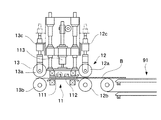
図3は、表面処理装置の側面図である。同図に示すように、この装置には、基材Bを押圧する押圧部11が設けられ、この押圧部11の上流側及び下流側に基材を搬送する第1及び第2ローラ部(駆動手段)12,13がそれぞれ配置されている。押圧部11は、基材Bを上下方向から挟む一対の押圧板(押圧部材)111,112とプレス機113とを備え、このプレス機113によって上側の押圧板111が押圧される。両押圧板111,112は、上下方向に所定間隔をおいて配置されており、その隙間が、基材Bが進入する通路となっている。そして、両押圧板111,112間の間隔は、基材Bの厚さよりも若干小さく設定されている。また、両押圧板111,112は、その間の隙間に基材Bがスムーズに進入するようにするため、次のように構成されている。すなわち、上側の押圧板111の端部を上向きに傾斜させる一方、下側の押圧板112の端部を下向きに傾斜させることで、押圧板111,112間の上流側の隙間を広くしている。また、上側の押圧板111には、図示を省略する加熱装置が設けられており、押圧板間を通過する基材Bを加熱できるようになっている。なお、各押圧板111,112は、例えば、クロームメッキがなされた金属板で形成され、基材Bと対向する面が平滑に形成されている。
FIG. 3 is a side view of the surface treatment apparatus. As shown in the figure, this apparatus is provided with a
各ローラ部12,13は、上下方向から基材Bを挟む駆動ローラ12a,13a及び従動ローラ12b,13bで構成されている。上側に配置された駆動ローラ12a,13aの各軸受けにはプレス機12c,13cが取り付けられており、駆動ローラ12a,13aは基材Bに対して圧力を付与しながら回転する。これにより、基材Bを強い力で前進させ、両押圧板111,112間の隙間に進入させることができる。
Each
図2に戻って、製造ラインの説明を続ける。表面処理装置1の下流には、上記のように接着剤塗布装置3が配設されている。接着剤塗布装置3は、基材Bに対して接着剤を塗布する公知のローラ(図示省略)が設けられている。すなわち、ローラの表面に塗布された接着剤が、基材Bの上面(一方面)を回転することで、ローラ表面の接着剤が基材Bの上面に転写されるように構成されている。ここで使用される接着剤としては、種々のものを使用することができるが、シートの初期接着性の観点から、PUR(Poly Urethane Reactive)型接着剤を使用することが好ましい。また、ここで用いられる接着剤の粘度は8000mPas以下であることが好ましく、6500mPas以下であることがさらに好ましく、5000mPas以下であることが特に好ましい。接着剤塗布装置3の下流側には、第3コンベア93が配設されており、接着剤が塗布された基材Bは、このコンベア93によってラミネート装置5へ搬送される。
Returning to FIG. 2, the description of the production line will be continued. As described above, the
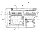
ラミネート装置5は、基材Bと化粧シートAとをラミネートする装置である。図4に示すように、ラミネート装置5には、製造ラインと平行に並ぶ待機部51が設けられており、この待機部51に枚葉の状態で配置された化粧シートAが、移動装置52によって製造ライン上に移動される。移動装置52は、製造ラインの上方でラインと垂直に延びるレール521を備えており、このレール521に沿って化粧シートAを保持する保持部522が移動するようになっている。保持部522は、レール521に沿って移動しつつシリンダ523によって上下方向に移動可能であり、化粧シートと当接する当接面522aを有している。この当接面522aには、複数の空気孔(図示省略)が形成されており、この空気孔から空気を吸引することで負圧を形成可能となっている。これにより、当接面522aに当接する化粧シートAを吸着保持することができる。そして、このラミネート装置5で形成された床材Sは、ラミネート装置5上の第4コンベア524によって押圧装置7へと搬送される。
The
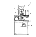
図5は押圧装置の側面図である。同図に示すように、この押圧装置7は、上下方向に並ぶ一対のローラ71,72で構成されている。下側に配置されたローラ72は軸受けに券回されたベルト73を介してモータ74と接続されており、駆動ローラを構成している。一方、上側に配置されたローラ71は従動ローラを構成している。この従動ローラ71の軸受けにはプレス機75が設けられており、このプレス機75によって従動ローラ71が駆動ローラ72に押しつけられている。そして、このように構成された両ローラ71,72の間を床材Sが通過する。
FIG. 5 is a side view of the pressing device. As shown in the figure, the
次に、上記のように構成された製造ラインによる床材の製造工程について説明する。まず、第1コンベア91によって基材Bを一枚ずつ表面処理装置1へ搬送する。搬送された基材Bは、第1ローラ部12によって挟まれながら前進し、押圧部11の隙間へ進入する。このとき、上側の押圧板111にはプレス機113によって圧力が作用しているため、基材Bは、表面を押圧されつつ前進する。これによって基材Bの表面は、擦られながら凹凸が均され平滑化される。基材Bにおいて押圧部11を通過した部分は、第2ローラ13に挟まれつつその回転によって下流側へ引っ張られる。このように、基材Bは、第1及び第2ローラ12,13の回転によって強い力で前進されるため、押圧板111,112による圧力に抗して下流側へ前進することが可能となっている。
Next, the manufacturing process of the flooring by the manufacturing line comprised as mentioned above is demonstrated. First, the base material B is conveyed to the surface treatment apparatus 1 one by one by the
このとき、押圧部11によって基材Bを押圧する圧力は、0.1〜0.5kg/cm2であることが好ましい。これは、圧力が0.1kg/cm2より小さいと基材表面の平滑化が不十分になる一方、0.5kg/cm2より大きいと、基材Bと押圧板112,113との摩擦力が大きすぎて、基材Bが前進しにくくなるからである。また、製造効率の観点から、第1及び第2ローラ12,13によって基材Bが前進する速度は、1m/min以上であることが好ましい。さらに、基材Bの表面を30〜60℃に加熱することが好ましく、この場合,押圧板112,113を150〜250℃にして基材Bの加熱を行うことか好ましい。
At this time, it is preferable that the pressure which presses the base material B by the
こうして、表面処理装置1を通過した基材は、第2コンベア92によって接着剤塗布装置3に搬送される。この接着剤塗布装置3では、ローラによって基材の上面に接着剤が塗布される。このとき、基材の表面に塗布される接着剤は、15〜100g/cm2であることが好ましい。
In this way, the base material that has passed through the surface treatment device 1 is conveyed to the
続いて、接着剤が塗布された基材Bは、第3コンベア93によって図4に示すラミネート装置5に搬送され、一旦停止される。これに続いて、待機部51に配置された化粧シートAが保持部522によって吸引保持された後、レール521に沿って製造ライン側へ移動し、基材Bの上方に位置決めされる。この状態から保持部522が下降して基材Bの上面に化粧シートAが当接すると、空気孔における空気の吸引を停止し、化粧シートAを保持部522から分離する。こうして、化粧シートAは、基材Bにラミネートされて床材Sが形成され、第4コンベア524によって押圧装置7へと搬送される。
Subsequently, the base material B to which the adhesive is applied is conveyed to the
図5に示す押圧装置7において両ローラ71,72の間に床材Sが進入すると、この床材Sは駆動ローラ72の回転によって前進し、両ローラ71,72の間を通過する。これにより、床材Sの表面が押圧されて接着剤が基材Bに浸透し、化粧シートAと基材Bとが強固に固着される。以上の工程を経ることによって床材が完成する。
When the floor material S enters between the
以上のように、本実施形態によれば、接着剤の塗布に先立って、表面処理装置1において基材Bの表面を押圧している。こうすることで、基材Bの表面の凹凸が均されて平滑化される。これにより次の効果を得ることができる。すなわち、基材表面に凹凸が存在すると、凹部に接着剤が入り込み易く、接着剤が余分に必要となる。これに対して、本実施形態のように構成すると、凹凸を均すことができ、余分な接着剤が使用されるのを防止することができる。その結果、接着剤の使用量を低減することができ、製造コストを低減することが可能となる。特に、濃度の低い接着剤を使用した場合には、接着剤で低粘度であることから凹部に入り込み易いため、このような製造ラインを用いると有利である。また、本実施形態では、基材表面を押圧するのに加え、加熱しているため、表面の平滑化を確実に行うことができる。 As described above, according to this embodiment, the surface of the base material B is pressed by the surface treatment apparatus 1 prior to the application of the adhesive. By carrying out like this, the unevenness | corrugation of the surface of the base material B is leveled and smoothed. As a result, the following effects can be obtained. That is, if there are irregularities on the surface of the base material, the adhesive easily enters the concave portions, and an extra adhesive is required. On the other hand, if comprised like this embodiment, an unevenness | corrugation can be leveled and it can prevent that an excess adhesive agent is used. As a result, the amount of adhesive used can be reduced, and the manufacturing cost can be reduced. In particular, when a low-concentration adhesive is used, it is advantageous to use such a production line because the adhesive has a low viscosity and can easily enter the recess. Moreover, in this embodiment, since it heats in addition to pressing the base-material surface, smoothing of the surface can be performed reliably.
さらに、基材表面が平滑化されるため、接着剤を均一に塗布することができる。これにより、接着力にバラツキが生じるのを防止することができ、化粧シートAが基材Bからはがれたり、部分的に基材Bから浮き上がったりするのを確実に防止することができる。 Furthermore, since the substrate surface is smoothed, the adhesive can be applied uniformly. Thereby, it is possible to prevent the adhesive force from being varied, and it is possible to reliably prevent the decorative sheet A from being peeled off from the base material B or partially from the base material B.
以上、本発明の一実施形態について説明したが、本発明はその趣旨を逸脱しない限りにおいて種々の変更が可能である。例えば、上記実施形態では、基材表面の押圧時に、押圧板によって基材Bを加熱しているが、加熱は必ずしも必要ではなく、押圧のみでも基材表面の平滑化は可能である。但し、より確実な平滑化のためには、基材表面の加熱を行うことが好ましい。 As mentioned above, although one Embodiment of this invention was described, this invention can be variously changed unless it deviates from the meaning. For example, in the above-described embodiment, the substrate B is heated by the pressing plate when the substrate surface is pressed. However, heating is not always necessary, and the substrate surface can be smoothed only by pressing. However, for more reliable smoothing, it is preferable to heat the substrate surface.
また、上記実施形態では、表面処理装置1において基材を前進させる駆動手段として、第1及び第2ローラ部12,13を用いているが、これに限定されるものではなく、基材Bを両押圧板111,112の間に進入させて通過させることができるものであればよい。
Moreover, in the said embodiment, although the 1st and
1 表面処理装置
11 押圧部
111 押圧板(押圧部材)
12 第1ローラ部(駆動手段)
13 第2ローラ部(駆動手段)
DESCRIPTION OF SYMBOLS 1
12 1st roller part (drive means)
13 Second roller part (drive means)
Claims (6)
表面が平滑な板状の押圧部材で基材の一方面を押圧する第1工程と、
押圧された基材の一方面に、接着剤を塗布する第2工程と、
接着剤が塗布された基材の一方面に化粧シートをラミネートする第3工程とを備え、
前記第1工程では、前記押圧部材によって基材の表面を押圧した状態で、当該基材を移動させる床材の製造方法。 A method for producing a flooring material in which a decorative sheet is laminated to a base material made of wood via an adhesive,
A first step of pressing one surface of the substrate with a plate-like pressing member having a smooth surface;
A second step of applying an adhesive to one side of the pressed substrate;
A third step of laminating a decorative sheet on one side of the base material coated with the adhesive ,
In the first step, the floor material manufacturing method of moving the base material while the surface of the base material is pressed by the pressing member .
基材が通過する通路が形成された押圧部と、
前記通路内に、基材を通過させる駆動手段とを備え、
前記押圧部は、前記通路を通過中の基材の表面を加圧する平滑面を有する板状部を備えている表面処理装置。 In the production of a flooring material for laminating a decorative sheet after applying an adhesive to a base material made of wood, a surface treatment apparatus for performing a surface treatment of the base material prior to the application of the adhesive,
A pressing portion formed with a passage through which the substrate passes;
A driving means for passing the substrate through the passage;
The said press part is a surface treatment apparatus provided with the plate-shaped part which has a smooth surface which pressurizes the surface of the base material which is passing the said channel | path.
Priority Applications (1)
| Application Number | Priority Date | Filing Date | Title |
|---|---|---|---|
| JP2003342609A JP4482749B2 (en) | 2003-09-30 | 2003-09-30 | Floor material manufacturing method and surface treatment apparatus used therefor |
Applications Claiming Priority (1)
| Application Number | Priority Date | Filing Date | Title |
|---|---|---|---|
| JP2003342609A JP4482749B2 (en) | 2003-09-30 | 2003-09-30 | Floor material manufacturing method and surface treatment apparatus used therefor |
Publications (2)
| Publication Number | Publication Date |
|---|---|
| JP2005104049A JP2005104049A (en) | 2005-04-21 |
| JP4482749B2 true JP4482749B2 (en) | 2010-06-16 |
Family
ID=34536835
Family Applications (1)
| Application Number | Title | Priority Date | Filing Date |
|---|---|---|---|
| JP2003342609A Expired - Fee Related JP4482749B2 (en) | 2003-09-30 | 2003-09-30 | Floor material manufacturing method and surface treatment apparatus used therefor |
Country Status (1)
| Country | Link |
|---|---|
| JP (1) | JP4482749B2 (en) |
-
2003
- 2003-09-30 JP JP2003342609A patent/JP4482749B2/en not_active Expired - Fee Related
Also Published As
| Publication number | Publication date |
|---|---|
| JP2005104049A (en) | 2005-04-21 |
Similar Documents
| Publication | Publication Date | Title |
|---|---|---|
| JP4973783B2 (en) | Film sticking apparatus, film sticking method, and electronic paper manufacturing method | |
| CN100575000C (en) | Forming method of layered polishing pad | |
| CN101524924B (en) | Device and method for applying pictures to workpieces | |
| US20100112285A1 (en) | Methods for manufacturing laminate, device applied herewith, laminate obtained herewith, method for encasing substrates and encased substrate obtained herewith | |
| JP4296763B2 (en) | Substrate coating method, substrate, coating apparatus, laminate manufacturing method and laminate | |
| JP4482749B2 (en) | Floor material manufacturing method and surface treatment apparatus used therefor | |
| JP4461318B2 (en) | Laminating apparatus and floor material manufacturing method | |
| JP4366573B2 (en) | Manufacturing method for flooring | |
| JP4505682B2 (en) | Manufacturing method for flooring | |
| KR101866856B1 (en) | MDF laminated plywood seat system in the | |
| JP2002322440A (en) | Bonding tape, method for bonding, and for coating the substrate | |
| JP4243180B2 (en) | LAMINATE MATERIAL MANUFACTURING METHOD AND LAMINATE MATERIAL MANUFACTURING DEVICE | |
| KR20010094665A (en) | method for preparing roll compley thin plate for pattern wool amd apparatus therefor | |
| JP2007090187A (en) | Adhesive application device and method for producing flooring using the same | |
| US20240375395A1 (en) | Method for laminating a building panel core with a self-adhesive use layer and building panel core laminated with a self-adhesive use layer | |
| JP2886827B2 (en) | Manufacturing method of seat for seat | |
| TH2401001019A (en) | Methods for Laminating and Laminating Stations | |
| JP5515215B2 (en) | Cosmetic sheet sticking method and decorative sheet sticking unit | |
| JP3610869B2 (en) | Decorative plate manufacturing method | |
| JP5743761B2 (en) | Substrate laminating method | |
| JP2024112053A (en) | Surface processing system and laminator | |
| CN212194621U (en) | From type paper laminating device | |
| CN1074980C (en) | Method and device for introducing surface structures into laminated or substrate coverings | |
| JP2010042606A (en) | Lapping device and lapping method | |
| JP3614107B2 (en) | Manufacturing method of decorative panel |
Legal Events
| Date | Code | Title | Description |
|---|---|---|---|
| A621 | Written request for application examination |
Free format text: JAPANESE INTERMEDIATE CODE: A621 Effective date: 20060905 |
|
| A711 | Notification of change in applicant |
Free format text: JAPANESE INTERMEDIATE CODE: A711 Effective date: 20090313 |
|
| A521 | Request for written amendment filed |
Free format text: JAPANESE INTERMEDIATE CODE: A821 Effective date: 20090313 |
|
| A977 | Report on retrieval |
Free format text: JAPANESE INTERMEDIATE CODE: A971007 Effective date: 20090423 |
|
| A521 | Request for written amendment filed |
Free format text: JAPANESE INTERMEDIATE CODE: A523 Effective date: 20090501 |
|
| A131 | Notification of reasons for refusal |
Free format text: JAPANESE INTERMEDIATE CODE: A131 Effective date: 20090610 |
|
| A521 | Request for written amendment filed |
Free format text: JAPANESE INTERMEDIATE CODE: A523 Effective date: 20090806 |
|
| TRDD | Decision of grant or rejection written | ||
| A01 | Written decision to grant a patent or to grant a registration (utility model) |
Free format text: JAPANESE INTERMEDIATE CODE: A01 Effective date: 20100303 |
|
| A01 | Written decision to grant a patent or to grant a registration (utility model) |
Free format text: JAPANESE INTERMEDIATE CODE: A01 |
|
| A61 | First payment of annual fees (during grant procedure) |
Free format text: JAPANESE INTERMEDIATE CODE: A61 Effective date: 20100309 |
|
| R150 | Certificate of patent or registration of utility model |
Ref document number: 4482749 Country of ref document: JP Free format text: JAPANESE INTERMEDIATE CODE: R150 Free format text: JAPANESE INTERMEDIATE CODE: R150 |
|
| FPAY | Renewal fee payment (event date is renewal date of database) |
Free format text: PAYMENT UNTIL: 20130402 Year of fee payment: 3 |
|
| FPAY | Renewal fee payment (event date is renewal date of database) |
Free format text: PAYMENT UNTIL: 20140402 Year of fee payment: 4 |
|
| LAPS | Cancellation because of no payment of annual fees |