JP4481879B2 - Switching power supply - Google Patents
Switching power supply Download PDFInfo
- Publication number
- JP4481879B2 JP4481879B2 JP2005163942A JP2005163942A JP4481879B2 JP 4481879 B2 JP4481879 B2 JP 4481879B2 JP 2005163942 A JP2005163942 A JP 2005163942A JP 2005163942 A JP2005163942 A JP 2005163942A JP 4481879 B2 JP4481879 B2 JP 4481879B2
- Authority
- JP
- Japan
- Prior art keywords
- power supply
- switching
- voltage
- supply voltage
- control circuit
- Prior art date
- Legal status (The legal status is an assumption and is not a legal conclusion. Google has not performed a legal analysis and makes no representation as to the accuracy of the status listed.)
- Expired - Fee Related
Links
Images


Classifications
-
- B—PERFORMING OPERATIONS; TRANSPORTING
- B23—MACHINE TOOLS; METAL-WORKING NOT OTHERWISE PROVIDED FOR
- B23K—SOLDERING OR UNSOLDERING; WELDING; CLADDING OR PLATING BY SOLDERING OR WELDING; CUTTING BY APPLYING HEAT LOCALLY, e.g. FLAME CUTTING; WORKING BY LASER BEAM
- B23K9/00—Arc welding or cutting
- B23K9/10—Other electric circuits therefor; Protective circuits; Remote controls
- B23K9/1006—Power supply
- B23K9/1043—Power supply characterised by the electric circuit
- B23K9/1056—Power supply characterised by the electric circuit by using digital means
Landscapes
- Engineering & Computer Science (AREA)
- Physics & Mathematics (AREA)
- Plasma & Fusion (AREA)
- Mechanical Engineering (AREA)
- Dc-Dc Converters (AREA)
Description
本発明は、スイッチング電源装置に関し、特に待機時の省電力化と定常負荷動作時の高効率化を可能とする装置に関する。 The present invention relates to a switching power supply apparatus, and more particularly to an apparatus that enables power saving during standby and high efficiency during steady load operation.
従来の降圧型スイッチング電源装置例を図9、10、11に示す。降圧型スイッチング電源装置として、一般的に、図9、10に示すようにハイサイドブロックの制御電源を確保するためにブートストラップ回路を有する電源と、図11に示すようにブートストラップ回路を有さずにハイサイドブロックのみでスイッチング電源をコントロールする電源がある。 Examples of conventional step-down switching power supply devices are shown in FIGS. As a step-down switching power supply device, generally, a power supply having a bootstrap circuit for securing a control power supply for a high-side block as shown in FIGS. 9 and 10 and a bootstrap circuit as shown in FIG. There is a power supply that controls the switching power supply using only the high-side block.
図9に第1の従来例(特開2000−350440号公報)を示す。図9に示す第1の従来例における制御回路108はグランド端子106を基準として動作し、ハイサイドのスイッチングデバイス107がオン状態におけるスイッチングデバイス107の制御電源を、ハイサイドのスイッチングデバイス107がオフ状態に、入力電源101からダイオード109を介して電流供給されたブートストラップ回路111のコンデンサ110の両端電圧から得ることで、電源として動作させる。
FIG. 9 shows a first conventional example (Japanese Patent Laid-Open No. 2000-350440). The
図10に第2の従来例(特開2001−112241号公報)を示す。図10に示す電源装置は図9の第1の従来例同様にブートストラップ回路を有する同期整流式で、図9の第1の従来例と比較して、図9中のダイオード103をスイッチングデバイス202に変更されている点が大きく異なる。スイッチングデバイス201と202は同時にオン状態とならないようにレベルシフト回路209を設けられ、一方がオン状態のときは他方がオフ状態となるように制御される。ローサイドにダイオードの代わりにスイッチングデバイスを使用することで、ハイサイドのスイッチングデバイスがオフ状態における図9のダイオード103両端に発生する電圧降下分をスイッチングデバイス202のオン抵抗による電圧降下に低減させることで電源効率を向上させる。
FIG. 10 shows a second conventional example (Japanese Patent Laid-Open No. 2001-112241). The power supply device shown in FIG. 10 is a synchronous rectification type having a bootstrap circuit as in the first conventional example of FIG. 9, and the
このように、図10の同期整流式降圧型スイッチング電源装置の主な特徴は、以下の2点である。
(1)例えば図9の従来例において、一般的にハイサイドのスイッチング素子107に流れる電流が高くなると、ハイサイドのスイッチング素子107がオフ状態において、ダイオード103に流れる電流も高くなるので順方向電圧も高くなるため、このダイオード103による電力損失も高くなる。そこで、このダイオード103と並列に低オン抵抗のスイッチング素子を接続(又は、従来例図10に示すようにダイオードの変わりにスイッチング素子202を使用する)し、導通状態において発生する電圧をダイオード103の順方向電圧よりも低くすることで電力損失を低減させる。
(2)このハイサイドとローサイドにそれぞれ接続されたスイッチング素子を同時オン状態とならない様にPWM制御によりオンオフ制御させる。
Thus, the main features of the synchronous rectification step-down switching power supply device of FIG. 10 are the following two points.
(1) For example, in the conventional example of FIG. 9, when the current flowing through the high-
(2) On / off control is performed by PWM control so that the switching elements respectively connected to the high side and the low side are not simultaneously turned on.
また、図11に第3の従来例(特開平10−191625号公報)を示す。図11において、VOUTは出力端子電圧、IOUTは出力端子電流、VDSはスイッチングデバイス302のDRAIN−SOURCE端子間電圧、IDSはスイッチングデバイス302に流れるDRAIN電流、VCCは図11中のCONTROL端子電圧をそれぞれ意味する。回路構成としては、入力コンデンサ301、スイッチングデバイス302とスイッチングデバイス302の制御回路303、制御回路基準電圧用コンデンサ304、変換回路305、出力電圧検出回路309、及び保護素子310からなる。
FIG. 11 shows a third conventional example (Japanese Patent Laid- Open No. 10-191625 ). 11, VOUT is an output terminal voltage, IOUT is an output terminal current, VDS is a DRAIN-SOURCE terminal voltage of the
スイッチングデバイス302のDRAIN端子に、入力端子電圧VIN(商用の交流電源をダイオードブリッジなどの整流器により整流された電圧を入力コンデンサ301により平滑した電圧、又は直流電圧)を印加すると、制御回路303の内部回路電流供給回路311により、スイッチ312を介してCONTROL端子に接続された制御回路基準電圧用コンデンサ304に電流が供給されることでVCCが上昇し、制御回路303がスイッチングデバイス302のオンオフ制御を開始する。ここで、スイッチングデバイス302のオンオフ制御は、内部の発振器313の出力信号である三角波とVCCを2つの抵抗314、315で分割された電圧をコンパレータ316により比較することで行われる。
When an input terminal voltage VIN (a voltage obtained by smoothing a commercial AC power supply voltage rectified by a rectifier such as a diode bridge or a DC voltage by a input capacitor 301) is applied to the DRAIN terminal of the
スイッチングデバイス302のオンオフ制御が開始すると、ダイオード306、コイル307、出力コンデンサ308から構成される変換回路305に電力が供給され、VOUTが上昇する。VOUTは出力電圧検出回路309により検出され、VOUTが規定値以上となると、スイッチングデバイス302がオフ状態において、OUT端子から制御回路303のCONTROL端子に電流が流れる。これにより、VCCが上昇し、コンパレータ316の出力信号のオンデューティーが小さくなることでスイッチングデバイス302のオンデューティーも小さくなり、スイッチングデバイス302のPWM制御が成される。
When the on / off control of the
以上のように、PWM制御方式では、出力が軽負荷になるにつれて、徐々にスイッチングデバイスのオンデューティーを小さくする(結果的にスイッチングデバイスに流れる電流IDSのピーク値は下がる)ことで、出力電圧の安定化と省電力化を図るというものである。 As described above, in the PWM control method, as the output becomes lighter, the on-duty of the switching device is gradually reduced (as a result, the peak value of the current IDS flowing through the switching device is lowered), so that the output voltage is reduced. It aims to stabilize and save power.
図12に第4の従来例(特開2003−189632公報)を示す。同図は、HVIC(高耐圧ドライバIC)回路450、451、452を使用したモータのインバータ駆動用ブリッジ回路であり、ハーフブリッジ回路を3つ並列に接続して、各出力端子をモータと接続した3相モータの駆動回路になっている。インバータ駆動用主直流電源423の高電位側と低電位側の間には、U、V、W相の3相のブリッジ回路のパワースイッチング素子417、418、419、420、421、422が接続されており、それらのパワースイッチング素子と並列に、ダイオード431、432、433、434、435、436が接続されている。
FIG. 12 shows a fourth conventional example (Japanese Patent Laid-Open No. 2003-189632). This figure shows a bridge circuit for driving an inverter of a motor using HVIC (High Voltage Driver IC)
HVIC回路450は、入力信号処理回路402、パワー素子駆動回路412およびフォトカプラと電気的絶縁機能を有するレベルシフト回路437から構成され、U、V、Wの各相毎に1チップ化した回路構成となっている。このHVIC回路はU、V、Wの3相を1チップ化した回路構成のデバイスもある。
The
そして、3つのHVIC回路の各基準電位端子と低電位側パワースイッチング素子の各エミッタ端子が、U、V、W相毎に接続されている。高電位側パワースイッチング素子の各エミッタ端子は、HVIC回路のレベルシフト回路と結ばれている高電位側駆動回路の第2の基準電位端子と、それぞれがU、V、W相毎に接続されている。また、HVIC回路の出力駆動信号端子は各パワースイッチング素子のゲート端子と接続されている。 The reference potential terminals of the three HVIC circuits and the emitter terminals of the low potential side power switching element are connected for each of the U, V, and W phases. Each emitter terminal of the high-potential side power switching element is connected to the second reference potential terminal of the high-potential side drive circuit connected to the level shift circuit of the HVIC circuit, for each of the U, V, and W phases. Yes. The output drive signal terminal of the HVIC circuit is connected to the gate terminal of each power switching element.
各々のパワースイッチング素子を駆動するための制御信号を生成するマイコン等の出力ポートにHVIC回路の入力信号処理回路が接続され、各HVIC回路の制御・駆動用電力は外部電源430より供給される。HVIC回路の高電位側パワースイッチング素子を駆動するための電力は、外部電源430とU、V、Wの相毎に高耐圧ダイオード440、441、442、コンデンサ443、444、445がそれぞれ直列に接続され、コンデンサ443、444、445の両端が高電位側パワースイッチング素子の駆動回路両端と接続されているブートストラップ電源回路より供給される。
An input signal processing circuit of the HVIC circuit is connected to an output port of a microcomputer or the like that generates a control signal for driving each power switching element, and power for controlling and driving each HVIC circuit is supplied from an
実際のモータをインバータ駆動する場合は、マイコンのインバータ駆動用の制御信号生成回路から各U、V、W相のHVIC回路へ制御信号が伝達され、駆動信号に従ってU、V、W各相のブリッジ回路の高電位側と低電位側の各パワースイッチング素子をスイッチングさせることにより、各出力端子間に交流電力を供給することでモータ制御を行っている。 When an actual motor is driven by an inverter, a control signal is transmitted from the control signal generation circuit for driving the inverter of the microcomputer to each U, V, W phase HVIC circuit, and the U, V, W phase bridges according to the drive signal The motor control is performed by supplying AC power between the output terminals by switching the power switching elements on the high potential side and the low potential side of the circuit.
このブリッジ駆動回路においては、ブートストラップ電源回路で、高電位側パワースイッチング回路を駆動している。このブートストラップ電源回路の動作は、主直流電源がブリッジ回路に印加された状態で、低電位側パワースイッチング素子を駆動するマイコン駆動信号がHVICに伝達され、低電位側パワースイッチング素子がオン状態になる。この状態では外部電源→高耐圧ダイオード→コンデンサ→低電位側パワースイッチング素子→外部電源の基準端子の順番で電流が流れることで、コンデンサの両端に、
Vcap=V(外部電源電圧)−Vf−Vc (V) ・・・・(1)
Vf:高耐圧ダイオードの順方向降下電圧
Vc:低電位側パワースイッチング素子のコレクタ電位
で表される電圧Vcapが充電される。
In this bridge driving circuit, the high potential side power switching circuit is driven by the bootstrap power supply circuit. The operation of the bootstrap power supply circuit is as follows. In the state where the main DC power supply is applied to the bridge circuit, the microcomputer drive signal for driving the low potential side power switching element is transmitted to the HVIC, and the low potential side power switching element is turned on. Become. In this state, the current flows in the order of the external power supply-> high voltage diode->capacitor-> low potential side power switching element-> external power supply reference terminal.
Vcap = V (external power supply voltage) −Vf−Vc (V) (1)
Vf: forward voltage drop of the high voltage diode Vc: a voltage Vcap expressed by the collector potential of the low potential side power switching element is charged.
HVIC回路の高電位側パワースイッチング素子を駆動する駆動回路は、このコンデンサに充電された電力により動作が維持される。従って、インバータ駆動回路に、主直流電源が印加された時は、コンデンサ443、444、445には電荷が充電されていないので、高電位側駆動回路は動作不可能の状態にある。
The drive circuit that drives the high potential side power switching element of the HVIC circuit is maintained in operation by the electric power charged in the capacitor. Therefore, when main DC power is applied to the inverter drive circuit, the
主直流電源を印加後は、まず各相の低電位側パワースイッチング素子が一定時間オンとなる駆動信号をマイコンからHVIC回路に伝達して、コンデンサ443、444、445に電力を充電する必要がある。その後、モータ駆動用の制御信号をマイコンから各HVIC回路へ伝達することでモータ制御が実現する。
After the main DC power supply is applied, first, it is necessary to charge the
コンデンサ443、444、445の両端電圧は、定期的に充電されなければ自然放電現象により、一定時間後にはパワースイッチング素子を駆動するために十分な電圧以下に低下する。そのため、モータ駆動時においても、インバータ駆動回路の定数によって決定される最大時間以内に、低電位側パワースイッチング素子をオンさせる信号をHVIC回路に伝達して、コンデンサ443、444、445に電力を充電する制御信号でモータ制御を実施している。
しかし、図10の同期整流式には、以下の3つの課題がある。
(1)入力電源電圧は一般的に20V程度までである。これは、PWM制御をさせるためのハイサイドのスイッチング素子制御回路部とローサイドのスイッチング素子制御回路部間の信号伝達が必要であるからである。
(2)入力電源電圧が20V程度以上となると、ハイサイドのスイッチング素子制御回路部への電源電圧供給のためのブートストラップ回路(図9の111や図10の203)と信号伝達のためのレベルシフト回路(図10の209)が必要である。ブートストラップ回路を介したハイサイドのスイッチング素子制御回路部へ電源電圧供給とレベルシフト回路によるローサイドからハイサイドへの信号伝達は、ハイサイドのスイッチング素子がオフの状態(すなわちローサイドのスイッチング素子がオン状態)のときのみという制約を有する。そのため、ハイサイドのスイッチング素子がオン状態において、ハイサイドのスイッチング素子制御回路電源電圧が自然放電により徐々に低下する(すなわちハイサイドのスイッチング素子制御回路の不安定動作となり得る)ため、ハイサイドのスイッチング素子のオン時間制御が非常に難しくなる。このことは、次の(3)についても同様である。
(3)例えば、60V程度以上のように、更に高い入力電源電圧下で使用する場合、第4の従来例(図12)におけるモータのインバータ駆動用ブリッジ回路に示すように、ハイサイドのスイッチング素子制御回路電源のためのブートストラップ回路は、ダイオード440とコンデンサ443で構成され、ハイサイドのスイッチング素子417の高電位側端子に接続された電源423とは別の電源430に接続されるため、2つ以上の入力電源が必要になる。
However, the synchronous rectification type in FIG. 10 has the following three problems.
(1) The input power supply voltage is generally up to about 20V. This is because signal transmission between the high-side switching element control circuit unit and the low-side switching element control circuit unit for PWM control is necessary.
(2) When the input power supply voltage is about 20 V or more, the bootstrap circuit (111 in FIG. 9 and 203 in FIG. 10) for supplying the power supply voltage to the high-side switching element control circuit unit and the level for signal transmission A shift circuit (209 in FIG. 10) is required. Power supply voltage supply to the high-side switching element control circuit section via the bootstrap circuit and signal transmission from the low side to the high side by the level shift circuit are in a state where the high-side switching element is off (that is, the low-side switching element is on). State)). Therefore, when the high-side switching element is in the ON state, the power supply voltage of the high-side switching element control circuit gradually decreases due to natural discharge (that is, an unstable operation of the high-side switching element control circuit). It becomes very difficult to control the on-time of the switching element. The same applies to the following (3).
(3) For example, when used under a higher input power supply voltage such as about 60 V or higher, as shown in the inverter drive bridge circuit of the motor in the fourth conventional example (FIG. 12), the high-side switching element The bootstrap circuit for the control circuit power supply includes a
このように、上記従来の降圧型スイッチング電源装置では、以下の理由により、スイッチング電源装置の小型化、電源効率の向上、更には待機状態、特に無負荷状態における更なる消費電力の削減は期待できない。
(1)第3の従来例における降圧型スイッチング電源装置において、PWM制御方式における無負荷状態では、スイッチングデバイスに流れる電流のピーク値は下がるが、スイッチング回数は負荷状態によらず一定であるため、更なる低消費電力化は困難である。
(2)第1、第2の従来例における降圧型スイッチング電源装置では、外付けにブートストラップ回路が必要なため、電源装置自体の小型化に支障が出る。
(3)第1、第2の従来例における降圧型スイッチング電源装置では、ハイサイドのスイッチングデバイスのオン・オフ制御はブートストラップ回路のコンデンサ両端電圧にて行われており、このコンデンサ両端電圧の低下による制御精度悪化やスイッチングデバイスのゲート電圧変動によるドレイン電流変動も発生しやすい。
(4)第1、第2の従来例における降圧型スイッチング電源装置では、比較的低電圧でしか使用することが困難であるため、入力電圧範囲に制限が発生する。
(5)第3の従来例における降圧型スイッチング電源装置では、第1の従来例同様にローサイドがダイオードで構成されるため、定常動作状態におけるダイオードでの電力損失が高くなり、更なる高電源効率化の支障となる。
(6)第4の従来例のような高入力電源電圧の場合、制御回路用とスイッチング素子用に2電源を必要とする。
As described above, the conventional step-down switching power supply device cannot be expected to reduce the size of the switching power supply device, improve the power supply efficiency, and further reduce the power consumption in the standby state, particularly in the no-load state, for the following reasons. .
(1) In the step-down switching power supply device according to the third conventional example, the peak value of the current flowing through the switching device decreases in the no-load state in the PWM control method, but the number of times of switching is constant regardless of the load state. It is difficult to further reduce power consumption.
(2) Since the step-down switching power supply in the first and second conventional examples requires an external bootstrap circuit, there is an obstacle to miniaturization of the power supply itself.
(3) In the step-down switching power supply apparatus in the first and second conventional examples, the on / off control of the high-side switching device is performed by the voltage across the capacitor of the bootstrap circuit. Deterioration of control accuracy due to, and drain current fluctuation due to switching device gate voltage fluctuation are also likely to occur.
(4) Since the step-down switching power supply devices in the first and second conventional examples are difficult to use only at a relatively low voltage, the input voltage range is limited.
(5) In the step-down switching power supply device according to the third conventional example, the low side is constituted by a diode as in the first conventional example, so that the power loss at the diode in a steady operation state is increased, and further high power supply efficiency is achieved. It will be a hindrance.
(6) In the case of a high input power supply voltage as in the fourth conventional example, two power supplies are required for the control circuit and the switching element.
本発明は上記従来の問題点を解決するもので、スイッチング電源装置のさらなる低消費電力化、小型化、および高効率化を目的とする。 The present invention solves the above-described conventional problems, and aims to further reduce the power consumption, size, and efficiency of the switching power supply.
上記目的を達成するために本発明のスイッチング電源装置は、第1電源電圧を供給する第1電源電圧供給器と、PWM信号を生成するPWM信号生成器と、PWM信号に基づいて、第1電源電圧をスイッチングする第1スイッチング器と、スイッチングされた第1電源電圧を第2電源電圧に変換する変換器と、第2電源電圧と所定の基準電圧との差を誤差信号として出力する誤差信号検出器と、誤差信号が所定の第1閾値以下の場合、第1スイッチング器のスイッチング動作を停止させる間欠制御器とを有し、PWM信号生成器は、誤差信号に基づいてパルス幅を変化させPWM信号を生成することを特徴としている。 In order to achieve the above object, a switching power supply of the present invention includes a first power supply voltage supplier that supplies a first power supply voltage, a PWM signal generator that generates a PWM signal, and a first power supply based on the PWM signal. A first switch that switches the voltage; a converter that converts the switched first power supply voltage to a second power supply voltage; and an error signal detection that outputs a difference between the second power supply voltage and a predetermined reference voltage as an error signal. And an intermittent controller that stops the switching operation of the first switching device when the error signal is equal to or less than a predetermined first threshold, and the PWM signal generator changes the pulse width based on the error signal and performs PWM It is characterized by generating a signal.
また上記目的を達成するために本発明のスイッチング電源装置は、第1電源電圧を供給する第1電源電圧供給器と、PWM信号を生成するPWM信号生成器と、PWM信号に基づいて、第1電源電圧をスイッチングする第1スイッチング器と、スイッチングされた第1電源電圧を第2電源電圧に変換する変換器と、第2電源電圧と所定の基準電圧との差を誤差信号として出力する誤差信号検出器と、誤差信号を電流変換する電流変換器と、電流変換された誤差信号を電圧変換する電圧変換器と、第1電源電圧を所定の第3電源電圧に変換し、PWM信号生成器と電圧変換器に第3電源電圧を供給する第1レギュレータと、第2電源電圧を所定の第4電源電圧に変換し、誤差信号検出器と電流変換器に第4電源電圧を供給する第2レギュレータとを有し、PWM信号生成器は、電圧変換された誤差信号に基づいてPWM信号を生成することを特徴としている。 In order to achieve the above object, the switching power supply apparatus of the present invention includes a first power supply voltage supplier that supplies a first power supply voltage, a PWM signal generator that generates a PWM signal, and a first signal based on the PWM signal. A first switch for switching the power supply voltage; a converter for converting the switched first power supply voltage to a second power supply voltage; and an error signal for outputting a difference between the second power supply voltage and a predetermined reference voltage as an error signal. A detector, a current converter for converting an error signal into a current, a voltage converter for converting a voltage of the converted error signal, a first power supply voltage into a predetermined third power supply voltage, and a PWM signal generator; A first regulator for supplying a third power supply voltage to the voltage converter; and a second regulator for converting the second power supply voltage to a predetermined fourth power supply voltage and supplying the fourth power supply voltage to the error signal detector and the current converter. Has, PWM signal generator is characterized in that for generating a PWM signal based on the voltage conversion error signal.
本発明のスイッチング電源装置は、上記構成を有し、従来例と比較して、広い入力電圧範囲で、待機状態、特に無負荷状態における更なる消費電力の削減と、定常動作状態における電源の高効率化を実現できる。 The switching power supply device of the present invention has the above-described configuration, and further reduces power consumption in a standby state, particularly in a no-load state, and increases the power supply in a steady operation state over a wide input voltage range as compared with the conventional example. Efficiency can be realized.
また、ブートストラップ回路が不要であり、且つ第1のスイッチングデバイスのゲート駆動電圧精度が向上するため、第1のスイッチングデバイスによる出力端子への電力供給も安定させることができる。 In addition, since the bootstrap circuit is unnecessary and the gate drive voltage accuracy of the first switching device is improved, the power supply to the output terminal by the first switching device can be stabilized.
以下、本発明の実施の形態を、図面を参照しながら説明する。
(第1の実施形態)
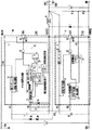
図1は本発明の第1の実施形態であるスイッチング電源装置を、図2は本発明の第1の実施形態であるスイッチング電源装置の出力の負荷状態が重負荷から軽負荷に移行したときの動作波形を表す。図1、2において、第1電源電圧VINは、第1電源電圧供給器によりグランド端子GNDのグランド電位を最下位電位として入力端子INに入力される電圧、第2電源電圧VOUTはグランド電位を最下位電位として出力端子OUTに出力される電圧、IOUTは出力端子OUTの電流、VDS1はスイッチングデバイスQ1のDRAIN1端子電圧、IFBはFB1端子電流(=FB2端子電流)、IDS1はスイッチングデバイスQ1に流れるDRAIN1端子電流をそれぞれ意味する。回路構成としては、入力コンデンサ1、スイッチングデバイスQ1とスイッチングデバイスQ1の制御回路3、制御回路基準電圧用第1コンデンサ4、第3ダイオード5とコイル6と出力コンデンサ7からなる変換回路、スイッチングデバイスQ2、スイッチングデバイスQ2のオンオフ制御と出力電圧検出を行う制御回路9、制御回路9の基準電圧用第2コンデンサ10、及び2つの抵抗R1とR2からなる。スイッチングデバイスQ1は、MOSトランジスタもしくは高耐圧トランジスタ等で構成される。
Hereinafter, embodiments of the present invention will be described with reference to the drawings.
(First embodiment)
FIG. 1 shows the switching power supply according to the first embodiment of the present invention, and FIG. 2 shows the state when the output load state of the switching power supply according to the first embodiment of the present invention shifts from a heavy load to a light load. Represents the operating waveform. 1 and 2, the first power supply voltage VIN is a voltage input to the input terminal IN with the ground potential of the ground terminal GND as the lowest potential by the first power supply voltage supplier, and the second power supply voltage VOUT is the ground potential of the highest. The voltage output to the output terminal OUT as a lower potential, IOUT is the current at the output terminal OUT, VDS1 is the DRAIN1 terminal voltage of the switching device Q1, IFB is the FB1 terminal current (= FB2 terminal current), and IDS1 is DRAIN1 flowing through the switching device Q1 Each terminal current is meant. The circuit configuration includes an
制御回路3は、図1に示すように、VIN1端子に接続され、第1電源電圧VINから制御回路3の各要素に電源電圧を供給する第3電源電圧をBY1端子に生成し、一定に制御する第1レギュレータ11、第3電源電圧が規定値以上なると制御回路3を起動、規定値以下になると制御回路3を停止させる起動/停止回路12、電源電圧として第3電源電圧がBY1端子から供給され、FB1端子から制御回路3の外部に流れ出す電流を出力電圧信号VLとして出力するI−V変換回路13、スイッチングデバイスQ1の最大オンデューティーを規定するMAX DUTY信号14と内部基準信号であるCLOCK信号15を出力する発振器16、I−V変換回路の出力電圧信号VLを基準電圧としてスイッチングデバイスQ1に流れるDRAIN1端子電流を検出し、スイッチングデバイスQ1をオフさせる過電流検出回路17、I−V変換回路の出力電圧信号VLが反転入力端子の第1閾値Vp1よりも低くなるとスイッチングデバイスQ1のオンオフ制御を休止、又は停止させ(このとき反転入力端子の閾値は第1閾値Vp1から第2閾値Vp2に変化する)、I−V変換回路の出力電圧信号VLが第2閾値Vp2よりも高くなるとスイッチングデバイスQ1のオンオフ制御を再開させる間欠発振制御回路18、間欠発振制御回路18の出力と発振器16のCLOCK信号15を入力信号とし、出力をフリップフロップ21のセット端子に出力するAND回路19、発振器16のMAX DUTY信号14の反転信号と過電流検出回路17の出力信号を入力し、フリップフロップ21のリセット端子に出力するOR回路20、フリップフロップ21、起動/停止回路12の出力信号と発振器16のMAX DUTY信号14とフリップフロップ21の出力信号を入力し、スイッチングデバイスQ1のGATE1端子を制御するAND回路22から構成されている。I−V変換回路13のFB1端子とSOURCE1端子間にはコンデンサ23と第2ダイオード24が接続されている。
As shown in FIG. 1, the control circuit 3 is connected to the VIN1 terminal, generates a third power supply voltage for supplying a power supply voltage from the first power supply voltage VIN to each element of the control circuit 3 at the BY1 terminal, and controls it to be constant. The
また、スイッチングデバイスQ2のオンオフ制御と出力電圧検出を行う制御回路9は、第2電源電圧VOUTから制御回路9の各要素に電源電圧を供給する第4電源電圧をBY2端子に生成し、一定に制御する第2レギュレータ25、BY2の電圧が規定値以上になると制御回路9を起動し、規定値以下になると制御回路9を停止させる起動/停止回路26、電源電圧として第4電源電圧がBY2端子から供給されるとともに、第2電源電圧VOUTの電圧を2つの抵抗R1とR2で分圧した信号を入力し、非反転入力端子に入力される基準電圧との電位差を誤差信号として増幅して出力する誤差増幅器27、電源電圧として第4電源電圧がBY2端子から供給され、誤差信号をFB2端子電流IFBに変換するV−I変換回路28、FB2端子電圧によりスイッチングデバイスQ1のオフ状態を検出するQ1オフ状態検出回路29、起動/停止回路26の出力信号がH(ハイ)のときQ1オフ状態検出回路29の出力信号によりスイッチングデバイスQ2のGATE2端子を制御するAND回路30から構成される。
In addition, the
入力端子INに、第1電源電圧VIN(商用の交流電源をダイオードブリッジなどの整流器により整流された電圧を入力コンデンサ1により平滑した電圧、又は直流電圧)を印加すると、制御回路3の第1レギュレータ11により、BY1端子に接続された制御回路基準電圧用第1コンデンサ4に電流が供給されることで、BY1端子電圧が上昇し、起動/停止回路12により制御回路3が動作し、スイッチングデバイスQ1のオンオフ制御が開始する。スイッチングデバイスQ1のオンオフ制御が開始すると、第3ダイオード5、コイル6、出力コンデンサ7から構成される変換回路に電力が供給され、出力端子OUTの第2電源電圧VOUTが上昇する。
When a first power supply voltage VIN (a voltage obtained by rectifying a commercial AC power supply rectified by a rectifier such as a diode bridge or a DC voltage) is applied to the input terminal IN, the first regulator of the control circuit 3 11, the current is supplied to the control circuit reference voltage
VOUTが上昇すると、第2レギュレータ25が動作し、制御回路9の基準電圧端子BY2の電圧が上昇する。基準電圧端子BY2の電圧が起動/停止回路26の規定値以上では制御回路9が起動し、誤差増幅器27による出力端子OUTの電圧検出が開始される。第2電源電圧VOUTは2つの抵抗R1とR2、及び誤差増幅器27により検出され、第2電源電圧VOUTが所望する電圧以上(正確にはVO1端子電圧が誤差増幅器27の非反転入力端子に入力される所定の基準電圧値以上)となると、誤差増幅器27の基準電圧とVO1端子電圧差を増幅し、誤差信号としてV−I変換回路28に伝達する。第2電源電圧VOUTが所望する電圧以上において、第2電源電圧VOUTが上昇すると誤差信号は線形的に減少し、そしてV−I変換回路28でFB2端子電流が増加するように変換され、更にI−V変換回路13の出力電圧信号VLが減少する。
When VOUT rises, the
VLは過電流検出回路17の基準電圧となっており、VLが減少することで、スイッチングデバイスQ1に流れるDRAIN1端子電流ピーク値を減少させる。これにより図2に示すように、DRAIN1端子電流IDS1は電流モードによるPWM制御となり、DRAIN1端子電圧VDS1はPWMスイッチングされる。すなわち発振器16、過電流検出回路17、OR回路20、フリップフロップ21はPWM信号生成器42を構成しており、PWM信号生成器42により生成されたPWM信号に基づいて、スイッチングデバイスQ1のGATE1端子におけるゲート電圧は制御され、スイッチングデバイスQ1はPWMスイッチングされる。PWM信号生成器42には、電源電圧として第3電源電圧がBY1端子から供給される。
VL is a reference voltage for the
そして、更に第2電源電圧VOUTが所望する電圧以上(出力負荷状態としては軽負荷状態)となり、I−V変換回路13の出力電圧信号VLが間欠発振制御回路18の第1閾値Vp1以下になると、出力負荷状態を軽負荷と判断し、間欠発振制御回路18はスイッチングデバイスQ1の休止、又は停止させる。スイッチングデバイスQ1のオンオフ制御が停止することで、出力への電力供給が停止するため、第2電源電圧VOUTは徐々に低下する。第2電源電圧VOUTの低下により、VLは徐々に上昇し、間欠発振制御回路18の第2閾値Vp2以上となると、スイッチングデバイスQ1のオンオフ制御が再開され、出力へ電力が供給される。これにより、第2電源電圧VOUTは再び上昇し、スイッチングデバイスQ1のオンオフ制御は停止する。軽負荷状態においては、これを繰り返す間欠制御となる。通常、第2閾値Vp2は、第1閾値Vp1より大きい値に設定される。
When the second power supply voltage VOUT further exceeds a desired voltage (light load state as the output load state), and the output voltage signal VL of the
ここで、制御回路3によるスイッチングデバイスQ1のPWM制御、及び間欠制御中において、スイッチングデバイスQ2は、スイッチングデバイスQ1がオフ状態のときのみにオンするようにスイッチングデバイスQ1のオフ状態をQ1オフ状態検出回路29でFB2端子電圧をモニターすることで検出し、AND回路30による制御される。スイッチングデバイスQ1オン時のDRAIN2−SOURCE2間電圧(図2中のVDS2で表されるIDS2×Ron(Q2))は、第3ダイオード5の順方向電圧Vfよりも低く設定されている。そして、第3ダイオード5は、スイッチングデバイスQ2のターンオン時間を改善するためにスイッチングデバイスQ2と並列接続されている。
Here, during PWM control and intermittent control of the switching device Q1 by the control circuit 3, the switching device Q2 detects the OFF state of the switching device Q1 so that the switching device Q1 is turned on only when the switching device Q1 is in the OFF state. The
このような本発明の第1の実施形態におけるスイッチング電源装置を使用した場合、広い入力範囲において、次のような効果が得られる。
(1)出力負荷状態が軽負荷になる程、スイッチングデバイスQ1に流れる電流のピーク値が減少することでPWM制御され、更に無負荷状態に近くなると間欠制御されるため、待機状態での更なる省電力化が実現できる。
(2)スイッチングデバイスQ1がオフ状態において、スイッチングデバイスQ2がオンすることで、第3ダイオード5の順方向電圧を更に低減させることが可能となり、定常動作状態における電源の高効率化を実現できる。
(3)ハイサイドの制御回路3とローサイドの制御回路9間の信号伝達において、ローサイドのV−I変換回路28とハイサイドのI−V変換回路13を設け、電流信号を用いた新しい信号伝達方式を採用することにより、高電圧電源時でもレベルシフト回路が不要でシンプルな構成を実現できる。
(4)高い入力電源電圧において必要となるブートストラップ回路やレベルシフト回路が不要であるため、入力電源電圧の範囲に関係無く、1つの入力電源電圧で同期整流式スイッチング電源装置を実現することが出来る。
(5)ハイサイドの制御回路3の電源電圧とローサイドの制御回路9の電源電圧は、それぞれ第1レギュレータ11と第2レギュレータ25により、常に一定となるように制御され、自然放電による電源電圧低下は発生しない。そのため、ハイサイドのスイッチングデバイスQ1のオン時間制御は容易である。
When such a switching power supply device according to the first embodiment of the present invention is used, the following effects are obtained in a wide input range.
(1) As the output load state becomes lighter, PWM control is performed by reducing the peak value of the current flowing through the switching device Q1, and intermittent control is performed when the output load state is closer to the no-load state. Power saving can be realized.
(2) Since the switching device Q2 is turned on while the switching device Q1 is in the off state, the forward voltage of the
(3) In signal transmission between the high-side control circuit 3 and the low-
(4) Since a bootstrap circuit and a level shift circuit required at a high input power supply voltage are not required, a synchronous rectification switching power supply device can be realized with one input power supply voltage regardless of the range of the input power supply voltage. I can do it.
(5) The power supply voltage of the high-side control circuit 3 and the power supply voltage of the low-
また、スイッチングデバイスQ1と制御回路3を、同一の半導体基板上に集積化すると良い。その際、DRAIN1端子、SOURCE1端子、BY1端子、及びFB1端子の少なくとも4つの端子を外部接続端子として集積化する。そして、4つ以上の端子を有したパッケージに組み込むことにより、部品点数が大幅に削減でき、部品の寸法も小さくなり、より小型・低価格の電源を実現できる。 Also, the switching device Q1 and the control circuit 3 are preferably integrated on the same semiconductor substrate. At that time, at least four terminals of the DRAIN1 terminal, the SOURCE1 terminal, the BY1 terminal, and the FB1 terminal are integrated as external connection terminals. By incorporating it into a package having four or more terminals, the number of components can be greatly reduced, the size of the components can be reduced, and a more compact and inexpensive power supply can be realized.
更に、スイッチングデバイスQ2と制御回路9を、それぞれ同一の半導体基板上に集積化すると良い。その際、DRAIN2端子、SOURCE2端子、BY2端子、及びFB2端子の少なくとも4つの端子を外部接続端子として集積化する。そして、4つ以上の端子を有したパッケージに組み込むことにより、部品点数が大幅に削減でき、部品の寸法も小さくなり、より小型・低価格の電源を実現できる。
Further, the switching device Q2 and the
更に、スイッチングデバイスQ1と制御回路3を同一の半導体基板上に集積化し、且つスイッチングデバイスQ2と制御回路9を同一の半導体基板上に集積化したものを、7つ以上の端子を有したパッケージに組み込むことにより、部品点数が大幅に削減でき、部品の寸法も小さくなり、より小型・低価格の電源を実現できる。
Further, the switching device Q1 and the control circuit 3 are integrated on the same semiconductor substrate, and the switching device Q2 and the
更に、スイッチングデバイスQ1と制御回路3を同一の半導体基板上に集積化し、且つスイッチングデバイスQ2と制御回路9を同一の半導体基板上に集積化したもの、制御回路3の基準電圧用第1コンデンサ4、制御回路9の基準電圧用第2コンデンサ10、コンデンサ23、第3ダイオード5、出力コンデンサ7、抵抗R1、R2を、DRAIN1端子、SOURCE1端子、SOURCE2端子、OUT端子の少なくとも4つの端子を外部端子として同一パッケージに組み込むことにより、部品点数が大幅に削減でき、部品の寸法も小さくなり、より小型・低価格の電源を実現できる。
Further, the switching device Q1 and the control circuit 3 are integrated on the same semiconductor substrate, and the switching device Q2 and the
ここでそれぞれ、スイッチングデバイスQ1は第1スイッチング器、スイッチングデバイスQ2は第2スイッチング器、間欠発振制御回路18は間欠制御器、誤差増幅器27は誤差信号検出器、I−V変換回路13は電圧変換器、V−I変換回路28は電流変換器、Q1オフ状態検出回路29は反転信号生成器、とも呼ぶ。また過電流検出回路17を含む回路を、過電流保護回路とも呼ぶ。
(第2の実施形態)
Here, the switching device Q1 is the first switching device, the switching device Q2 is the second switching device, the intermittent oscillation control circuit 18 is the intermittent controller, the
(Second Embodiment)
図3は、本発明の第2の実施形態であるスイッチング電源装置を表す。図1の第3ダイオード5のアノードに接続されている入力コンデンサ1の(−)端子を出力コンデンサ7の(+)端子に接続することにより、負出力電源を実現したものであり、第2電源電圧VOUTの最下位電位は、第1電源電圧VINの最下位電位から第2電源電圧VOUTを差し引いた電位になっている。すなはち、図1の第1の実施形態においては、第2電源電圧の極性は第1電源電圧の極性に対して同極性であったが、図3の第2の実施形態においては、第2電源電圧の極性は第1電源電圧の極性に対して逆極性になる。電源動作としては本発明の第1の実施形態におけるスイッチング電源装置と同じである。
FIG. 3 shows a switching power supply device according to the second embodiment of the present invention. A negative output power source is realized by connecting the (−) terminal of the
このような本発明の第2の実施形態におけるスイッチング電源装置を使用した場合、本発明の第1の実施形態と同じ効果が得られると共に、容易に出力電圧の極性を変えることが出来る。
(第3の実施形態)
When such a switching power supply device according to the second embodiment of the present invention is used, the same effects as those of the first embodiment of the present invention can be obtained, and the polarity of the output voltage can be easily changed.
(Third embodiment)
図4は、本発明の第3の実施形態であるスイッチング電源装置を表す。図1の制御回路9の第2レギュレータ25への電力供給源を第2電源電圧VOUTからではなく、直接第1電源電圧VINから得ているものであり、電源動作としては本発明の第1の実施形態におけるスイッチング電源装置と同じである。
このような本発明の第3の実施形態におけるスイッチング電源装置を使用した場合、本発明の第1の実施形態と同じ効果が得られると共に、出力の低電圧化に容易に対応することが可能となる。
(第4の実施形態)
FIG. 4 shows a switching power supply device according to the third embodiment of the present invention. The power supply source to the
When such a switching power supply device according to the third embodiment of the present invention is used, the same effects as those of the first embodiment of the present invention can be obtained, and it is possible to easily cope with a low output voltage. Become.
(Fourth embodiment)
図5は、本発明の第4の実施形態であるスイッチング電源装置を表す。図1の制御回路3に、スイッチングデバイスQ1のジャンクション温度が規定温度以上になると、スイッチングデバイスQ1のオンオフ制御を強制的に停止させる保護機能を果たす過熱保護回路33と、過熱保護回路33による停止状態を解除するための再起動トリガ回路34がAND回路22の入力に接続されているものであり、電源動作としては本発明の第1の実施形態におけるスイッチング電源装置と同じである。
FIG. 5 shows a switching power supply apparatus according to the fourth embodiment of the present invention. In the control circuit 3 of FIG. 1, when the junction temperature of the switching device Q1 becomes equal to or higher than the specified temperature, the overheat protection circuit 33 that performs a protection function for forcibly stopping the on / off control of the switching device Q1 and the stop state by the overheat protection circuit 33 The restart trigger circuit 34 for canceling is connected to the input of the AND
このような本発明の第4の実施形態におけるスイッチング電源装置を使用した場合、本発明の第1の実施形態と同じ効果が得られると共に、スイッチングデバイスの保護と、スイッチング電源装置の安全性確保が実現できる。
(第5の実施形態)
When the switching power supply device according to the fourth embodiment of the present invention is used, the same effects as those of the first embodiment of the present invention can be obtained, and the switching device can be protected and the switching power supply device can be secured. realizable.
(Fifth embodiment)
図6は、本発明の第5の実施形態であるスイッチング電源装置を表す。図1の制御回路3における第1レギュレータ11内部にVIN1端子に接続された接合型電界効果トランジスタJFET1を、そして図1の制御回路9におけるQ1オフ状態検出回路29内部にFB2端子に接続された接合型電界効果トランジスタJFET2を有しているものであり、電源動作としては本発明の第1の実施形態におけるスイッチング電源装置と同じである。
FIG. 6 shows a switching power supply apparatus according to the fifth embodiment of the present invention. A junction field effect transistor JFET1 connected to the VIN1 terminal in the
このような本発明の第5の実施形態におけるスイッチング電源装置を使用した場合、入力電圧が高電圧の場合でも、本発明の第1の実施形態と同じ効果が得られる。
(第6の実施形態)
When the switching power supply device according to the fifth embodiment of the present invention is used, the same effect as that of the first embodiment of the present invention can be obtained even when the input voltage is high.
(Sixth embodiment)
図7は、本発明の第6の実施形態であるスイッチング電源装置を表す。図7に示すように、第1の実施形態に加えて制御回路3の基準電圧端子BY1端子と出力端子OUTの間に第1ダイオード35とツェナーダイオード36を接続したものであり、電源動作としては本発明の第1の実施形態におけるスイッチング電源装置と同じである。
FIG. 7 shows a switching power supply device according to the sixth embodiment of the present invention. As shown in FIG. 7, in addition to the first embodiment, the
このような本発明の第6の実施形態におけるスイッチング電源装置を使用した場合、制御回路3の基準電圧端子BY1への電力供給を、第1レギュレータ11からでは無く、出力端子OUTからとなるために、待機状態での省電力化に関して、本発明の第1の実施形態以上の効果が得られる。
(第7の実施形態)
When such a switching power supply device according to the sixth embodiment of the present invention is used, the power supply to the reference voltage terminal BY1 of the control circuit 3 is not from the
(Seventh embodiment)
図8は、本発明の第7の実施形態であるスイッチング電源装置を表す。図1の過電流検出回路17の形態がセンスMOSトランジスタ37とセンス抵抗38とコンパレータで構成されており、電源動作としては本発明の第1の実施形態におけるスイッチング電源装置と同じである。
FIG. 8 shows a switching power supply device according to a seventh embodiment of the present invention. The form of the
このような本発明の第7の実施形態におけるスイッチング電源装置を使用した場合、本発明の第1の実施形態と同じ効果が得られる。
(実施の形態のまとめ)
When such a switching power supply device according to the seventh embodiment of the present invention is used, the same effect as that of the first embodiment of the present invention can be obtained.
(Summary of embodiment)
以上の実施の形態では、降圧型スイッチング電源装置について説明したが、本発明は降圧型だけに限定されるものではなく、昇圧型、昇降圧型を含むあらゆるスイッチング電源装置に適用可能である。また、実施の形態において展開した説明は、すべて本発明を具体化した一例であり、本発明はこれらの例に限定されるものではない。 In the above embodiment, the step-down switching power supply device has been described. However, the present invention is not limited to the step-down type, and can be applied to any switching power supply device including a step-up type and a step-up / step-down type. Moreover, all the descriptions developed in the embodiments are examples embodying the present invention, and the present invention is not limited to these examples.
本発明は、スイッチング電源装置に利用できる。 The present invention can be used for a switching power supply.
Q1 スイッチングデバイス
Q2 スイッチングデバイス
1 入力コンデンサ
3 制御回路
4 制御回路基準電圧用第1コンデンサ
5 第3ダイオード
6 コイル
7 出力コンデンサ
9 制御回路
10 第2コンデンサ
11 第1レギュレータ
12 起動/停止回路
13 I−V変換回路
14 MAX−DUTY信号
15 CLOCK信号
16 発振器
17 過電流検出回路
18 間欠発振制御回路
19 AND回路
20 OR回路
21 フリップフロップ
22 AND回路
23 コンデンサ
24 第2ダイオード
25 第2レギュレータ
26 起動/停止回路
27 誤差増幅器
28 V−I変換回路
29 Q1オフ状態検出回路
30 AND回路
R1 抵抗
R2 抵抗
33 過熱保護回路
34 再起動トリガ回路
35 第1ダイオード
36 ツェナーダイオード
37 センスMOSトランジスタ
38 センス抵抗
42 PWM信号生成器
101 入力電源
102 出力端子
103 ダイオード
104 出力コンデンサ
105 コイル
106 グランド端子
107 スイッチングデバイス
108 制御回路
109 ダイオード
110 コンデンサ
111 ブートストラップ回路
201 スイッチングデバイス
202 スイッチングデバイス
203 ブートストラップ回路
204 コイル
205 出力コンデンサ
206 抵抗
207 抵抗
208 PWMコントローラ
209 レベルシフト回路
301 入力コンデンサ
302 スイッチングデバイス
303 制御回路
304 コンデンサ
305 変換回路
306 ダイオード
307 コイル
308 出力コンデンサ
309 ダイオード
310 ツェナーダイオード
311 内部回路電流供給回路
312 スイッチ
313 発振器
314 抵抗
315 抵抗
316 コンパレータ
Q1 switching device
Claims (26)
PWM信号を生成するPWM信号生成手段と、
前記PWM信号に基づいて、前記第1電源電圧をスイッチングする第1スイッチング手段と、
前記スイッチングされた第1電源電圧を第2電源電圧に変換する変換手段と、
前記第2電源電圧と所定の基準電圧との差を誤差信号として出力する誤差信号検出手段と、
前記誤差信号が所定の第1閾値以下の場合、前記第1スイッチング手段のスイッチング動作を停止させる間欠制御手段と、
前記PWM信号の反転信号を生成する反転信号生成手段と、
前記第1スイッチング手段に接続され、前記反転信号に基づいてスイッチングする第2スイッチング手段と、
前記PWM信号生成手段及び前記間欠制御手段からなる第1制御回路と、
前記誤差信号検出手段及び前記反転信号生成手段からなる第2制御回路とを有し、
前記PWM信号生成手段は、前記誤差信号に基づいてパルス幅を変化させ、前記PWM信号を生成し、
前記第1スイッチング手段の基準電圧と前記第1制御回路の基準電圧は等しく、
前記第2スイッチング手段の基準電圧と前記第2制御回路の基準電圧は等しいことを特徴とする、スイッチング電源装置。 First power supply voltage supply means for supplying a first power supply voltage;
PWM signal generating means for generating a PWM signal;
First switching means for switching the first power supply voltage based on the PWM signal;
Conversion means for converting the switched first power supply voltage to a second power supply voltage;
Error signal detection means for outputting a difference between the second power supply voltage and a predetermined reference voltage as an error signal;
Intermittent control means for stopping the switching operation of the first switching means when the error signal is not more than a predetermined first threshold ;
An inverted signal generating means for generating an inverted signal of the PWM signal;
Second switching means connected to the first switching means for switching based on the inverted signal;
A first control circuit comprising the PWM signal generating means and the intermittent control means;
A second control circuit comprising the error signal detection means and the inverted signal generation means ,
The PWM signal generation means changes a pulse width based on the error signal, generates the PWM signal ,
The reference voltage of the first switching means and the reference voltage of the first control circuit are equal,
The switching power supply device according to claim 1, wherein a reference voltage of the second switching means is equal to a reference voltage of the second control circuit .
前記第2制御回路は、前記誤差信号を電流変換する電流変換手段と、
前記第2電源電圧を所定の第4電源電圧に変換し、前記第4電源電圧を前記誤差信号検出手段と前記電流変換手段に供給する第2レギュレータとを有し、
前記第1制御回路は、前記電流変換された誤差信号を電圧変換する電圧変換手段と、
前記第1電源電圧を所定の第3電源電圧に変換し、前記第3電源電圧を前記PWM信号生成手段と前記電圧変換手段に供給する第1レギュレータとを有し、
前記PWM信号生成手段は、前記電圧変換された誤差信号に基づいて前記PWM信号を生成することを特徴とする、請求項1記載のスイッチング電源装置。 Furthermore,
The second control circuit includes current conversion means for current-converting the error signal;
A second regulator that converts the second power supply voltage into a predetermined fourth power supply voltage and supplies the fourth power supply voltage to the error signal detection means and the current conversion means;
The first control circuit includes voltage conversion means for converting the current-converted error signal into voltage,
A first regulator that converts the first power supply voltage to a predetermined third power supply voltage and supplies the third power supply voltage to the PWM signal generation means and the voltage conversion means;
2. The switching power supply device according to claim 1, wherein the PWM signal generating means generates the PWM signal based on the voltage-converted error signal.
前記第1レギュレータの出力端子に接続された第1コンデンサを有することを特徴とする、請求項2記載のスイッチング電源装置。 Furthermore,
The switching power supply device according to claim 2, further comprising a first capacitor connected to an output terminal of the first regulator.
前記直列接続した回路は、前記第2電源電圧を前記第3電源電圧に変換することを特徴とする、請求項2から5のいずれかに記載のスイッチング電源装置。 Furthermore, it has a circuit in which a first diode and a Zener diode are connected in series,
6. The switching power supply device according to claim 2, wherein the circuit connected in series converts the second power supply voltage into the third power supply voltage. 7.
PWM信号を生成するPWM信号生成手段と、
前記PWM信号に基づいて、前記第1電源電圧をスイッチングする第1スイッチング手段と、
前記スイッチングされた第1電源電圧を第2電源電圧に変換する変換手段と、
前記第2電源電圧と所定の基準電圧との差を誤差信号として出力する誤差信号検出手段と、
前記誤差信号を電流変換する電流変換手段と、
前記電流変換された誤差信号を電圧変換する電圧変換手段と、
前記第1電源電圧を所定の第3電源電圧に変換し、前記第3電源電圧を前記PWM信号生成手段と前記電圧変換手段に供給する第1レギュレータと、
前記第2電源電圧を所定の第4電源電圧に変換し、前記第4電源電圧を前記誤差信号検出手段と前記電流変換手段に供給する第2レギュレータと、
前記PWM信号の反転信号を生成する反転信号生成手段と、
前記第1スイッチング手段に接続され、前記反転信号に基づいてスイッチングする第2スイッチング手段と、
前記PWM信号生成手段、前記電圧変換手段、及び前記第1レギュレータからなる第1制御回路と、
前記誤差信号検出手段、前記電流変換手段、前記第2レギュレータ、及び前記反転信号生成手段からなる第2制御回路とを有し、
前記PWM信号生成手段は、前記電圧変換された誤差信号に基づいてパルス幅を変化させ、前記PWM信号を生成し、
前記第1スイッチング手段の基準電圧と前記第1制御回路の基準電圧は等しく、
前記第2スイッチング手段の基準電圧と前記第2制御回路の基準電圧は等しいことを特徴とする、スイッチング電源装置。 First power supply voltage supply means for supplying a first power supply voltage;
PWM signal generating means for generating a PWM signal;
First switching means for switching the first power supply voltage based on the PWM signal;
Conversion means for converting the switched first power supply voltage to a second power supply voltage;
Error signal detection means for outputting a difference between the second power supply voltage and a predetermined reference voltage as an error signal;
Current conversion means for current-converting the error signal;
Voltage converting means for converting the current-converted error signal into a voltage;
A first regulator that converts the first power supply voltage to a predetermined third power supply voltage, and supplies the third power supply voltage to the PWM signal generation means and the voltage conversion means;
A second regulator that converts the second power supply voltage into a predetermined fourth power supply voltage and supplies the fourth power supply voltage to the error signal detection means and the current conversion means ;
An inverted signal generating means for generating an inverted signal of the PWM signal;
Second switching means connected to the first switching means for switching based on the inverted signal;
A first control circuit comprising the PWM signal generating means, the voltage converting means, and the first regulator;
A second control circuit comprising the error signal detection means, the current conversion means, the second regulator, and the inverted signal generation means ;
The PWM signal generating means changes a pulse width based on the voltage-converted error signal, generates the PWM signal ,
The reference voltage of the first switching means and the reference voltage of the first control circuit are equal,
The switching power supply device according to claim 1, wherein a reference voltage of the second switching means is equal to a reference voltage of the second control circuit .
前記第1レギュレータの出力端子に接続された第1コンデンサを有することを特徴とする、請求項14記載のスイッチング電源装置。 Furthermore,
The switching power supply device according to claim 14 , further comprising a first capacitor connected to an output terminal of the first regulator.
前記直列接続した回路は、前記第2電源電圧を前記第3電源電圧に変換することを特徴とする、請求項14から18のいずれかに記載のスイッチング電源装置。 Furthermore, it has a circuit in which a first diode and a Zener diode are connected in series,
The switching power supply according to any one of claims 14 to 18 , wherein the circuit connected in series converts the second power supply voltage into the third power supply voltage.
Priority Applications (2)
| Application Number | Priority Date | Filing Date | Title |
|---|---|---|---|
| JP2005163942A JP4481879B2 (en) | 2005-06-03 | 2005-06-03 | Switching power supply |
| US11/441,374 US7348766B2 (en) | 2005-06-03 | 2006-05-25 | Switching power supply device |
Applications Claiming Priority (1)
| Application Number | Priority Date | Filing Date | Title |
|---|---|---|---|
| JP2005163942A JP4481879B2 (en) | 2005-06-03 | 2005-06-03 | Switching power supply |
Publications (3)
| Publication Number | Publication Date |
|---|---|
| JP2006340538A JP2006340538A (en) | 2006-12-14 |
| JP2006340538A5 JP2006340538A5 (en) | 2007-02-01 |
| JP4481879B2 true JP4481879B2 (en) | 2010-06-16 |
Family
ID=37493461
Family Applications (1)
| Application Number | Title | Priority Date | Filing Date |
|---|---|---|---|
| JP2005163942A Expired - Fee Related JP4481879B2 (en) | 2005-06-03 | 2005-06-03 | Switching power supply |
Country Status (2)
| Country | Link |
|---|---|
| US (1) | US7348766B2 (en) |
| JP (1) | JP4481879B2 (en) |
Families Citing this family (24)
| Publication number | Priority date | Publication date | Assignee | Title |
|---|---|---|---|---|
| JP2009011045A (en) * | 2007-06-27 | 2009-01-15 | Nec Electronics Corp | Switching regulator and direct-current voltage conversion method |
| KR101079900B1 (en) * | 2007-10-31 | 2011-11-04 | 주식회사 케이티 | Static transfer switch device, power supply apparatus using the switch device and switching method thereof |
| KR20090050318A (en) * | 2007-11-15 | 2009-05-20 | 삼성전자주식회사 | Power converter having auto conversion function for pulse skip mode and control method of thereof |
| US8390146B2 (en) * | 2008-02-27 | 2013-03-05 | Panasonic Corporation | Semiconductor integrated circuit and various devices provided with the same |
| US8385088B2 (en) | 2010-12-06 | 2013-02-26 | Power Integrations, Inc. | Method and apparatus for implementing an unregulated dormant mode with output reset in a power converter |
| US7952895B2 (en) | 2008-05-29 | 2011-05-31 | Power Integrations, Inc. | Method and apparatus for implementing an unregulated dormant mode in a power converter |
| US7995359B2 (en) * | 2009-02-05 | 2011-08-09 | Power Integrations, Inc. | Method and apparatus for implementing an unregulated dormant mode with an event counter in a power converter |
| US7779278B2 (en) | 2008-05-29 | 2010-08-17 | Igo, Inc. | Primary side control circuit and method for ultra-low idle power operation |
| US7770039B2 (en) | 2008-05-29 | 2010-08-03 | iGo, Inc | Primary side control circuit and method for ultra-low idle power operation |
| JP5147554B2 (en) * | 2008-06-10 | 2013-02-20 | パナソニック株式会社 | Switching power supply device and semiconductor device used therefor |
| US7795759B2 (en) | 2008-06-27 | 2010-09-14 | iGo, Inc | Load condition controlled power strip |
| US7800252B2 (en) | 2008-06-27 | 2010-09-21 | Igo, Inc. | Load condition controlled wall plate outlet system |
| US7795760B2 (en) | 2008-07-25 | 2010-09-14 | Igo, Inc. | Load condition controlled power module |
| TWI363474B (en) * | 2008-11-13 | 2012-05-01 | Advanced Analog Technology Inc | Bootstrap circuit and bulk circuit thereof |
| JP5330084B2 (en) * | 2009-05-12 | 2013-10-30 | パナソニック株式会社 | Current detection circuit and switching regulator using the same |
| JP5629191B2 (en) | 2010-05-28 | 2014-11-19 | ルネサスエレクトロニクス株式会社 | Power supply |
| US9219411B2 (en) * | 2011-09-13 | 2015-12-22 | Intel Deutschland Gmbh | DC/DC converter, method for providing an output voltage on the basis of an input voltage and computer program |
| CN103079323B (en) * | 2013-02-06 | 2015-04-29 | 杭州士兰微电子股份有限公司 | Non-isolated LED (Light Emitting Diode) drive circuit not powered by auxiliary winding |
| JP2016174453A (en) * | 2015-03-16 | 2016-09-29 | 株式会社東芝 | Dc/dc converter |
| CN107925351B (en) * | 2015-07-15 | 2020-05-15 | 三菱电机株式会社 | Control circuit |
| CN107231084B (en) * | 2016-04-29 | 2023-12-12 | 上海良信电器股份有限公司 | Controllable power supply circuit with wide voltage input |
| DE202016104993U1 (en) | 2016-09-09 | 2017-12-12 | Deutsches Zentrum für Luft- und Raumfahrt e.V. | switching converters |
| JP7421958B2 (en) * | 2020-03-02 | 2024-01-25 | ローム株式会社 | drive device |
| CN112756748A (en) * | 2021-01-08 | 2021-05-07 | 上海广为焊接设备有限公司 | Control system and method for alternating current-direct current argon arc welding |
Family Cites Families (5)
| Publication number | Priority date | Publication date | Assignee | Title |
|---|---|---|---|---|
| JP3100914B2 (en) | 1996-12-25 | 2000-10-23 | 松下電器産業株式会社 | Switching power supply |
| JP3335587B2 (en) * | 1998-12-25 | 2002-10-21 | 富士通株式会社 | DC-DC converter circuit |
| JP2000350440A (en) | 1999-06-01 | 2000-12-15 | Murata Mfg Co Ltd | Stepdown switching power source circuit |
| JP2001112241A (en) | 1999-10-08 | 2001-04-20 | Nippon Avionics Co Ltd | Synchronous-rectification type dc/dc converter |
| JP3806644B2 (en) | 2001-12-13 | 2006-08-09 | 三菱電機株式会社 | Power semiconductor device |
-
2005
- 2005-06-03 JP JP2005163942A patent/JP4481879B2/en not_active Expired - Fee Related
-
2006
- 2006-05-25 US US11/441,374 patent/US7348766B2/en not_active Expired - Fee Related
Also Published As
| Publication number | Publication date |
|---|---|
| US20060273662A1 (en) | 2006-12-07 |
| US7348766B2 (en) | 2008-03-25 |
| JP2006340538A (en) | 2006-12-14 |
Similar Documents
| Publication | Publication Date | Title |
|---|---|---|
| JP4481879B2 (en) | Switching power supply | |
| US7262587B2 (en) | Circuit and method for controlling DC-DC converter | |
| US6980444B2 (en) | Switching power supply | |
| JP4687958B2 (en) | DC-DC converter | |
| US9331583B2 (en) | Switch mode power supply, control circuit and associated control method | |
| JP3571690B2 (en) | Switching power supply device and semiconductor device for switching power supply | |
| US7221129B2 (en) | Switching regulator and method for changing output voltages thereof | |
| US7714556B2 (en) | Quick response switching regulator and control method thereof | |
| JP4347249B2 (en) | DC-DC converter, control circuit for DC-DC converter, and control method for DC-DC converter | |
| US8193793B2 (en) | DC-DC converter | |
| US8310845B2 (en) | Power supply circuit with a control terminal for different functional modes of operation | |
| US20090201705A1 (en) | Energy converting apparatus, and semiconductor device and switching control method used therein | |
| JP3300683B2 (en) | Switching power supply | |
| WO2012147453A1 (en) | Direct current power supply device | |
| US10651759B2 (en) | Switching power supply device and semiconductor device | |
| JP2007142057A (en) | Light emitting diode driving device, and semiconductor device for driving light emitting diode | |
| JP2014023269A (en) | Semiconductor integrated circuit and method of operating the same | |
| US9780690B2 (en) | Resonant decoupled auxiliary supply for a switched-mode power supply controller | |
| JP2007174890A (en) | Switching power supply and semiconductor device used for it | |
| JP4173115B2 (en) | Switching power supply control semiconductor device | |
| JP3425403B2 (en) | Semiconductor device and switching power supply device using this semiconductor device | |
| JP6810150B2 (en) | Switching power supply and semiconductor device | |
| JP3490049B2 (en) | Switching power supply | |
| JP7543296B2 (en) | Switching control circuit and switching power supply device | |
| WO2022138540A1 (en) | Power supply control device |
Legal Events
| Date | Code | Title | Description |
|---|---|---|---|
| A521 | Written amendment |
Free format text: JAPANESE INTERMEDIATE CODE: A523 Effective date: 20061116 |
|
| A621 | Written request for application examination |
Free format text: JAPANESE INTERMEDIATE CODE: A621 Effective date: 20061116 |
|
| RD03 | Notification of appointment of power of attorney |
Free format text: JAPANESE INTERMEDIATE CODE: A7423 Effective date: 20061116 |
|
| A977 | Report on retrieval |
Free format text: JAPANESE INTERMEDIATE CODE: A971007 Effective date: 20090820 |
|
| A131 | Notification of reasons for refusal |
Free format text: JAPANESE INTERMEDIATE CODE: A131 Effective date: 20090908 |
|
| A521 | Written amendment |
Free format text: JAPANESE INTERMEDIATE CODE: A523 Effective date: 20091106 |
|
| TRDD | Decision of grant or rejection written | ||
| A01 | Written decision to grant a patent or to grant a registration (utility model) |
Free format text: JAPANESE INTERMEDIATE CODE: A01 Effective date: 20100216 |
|
| A01 | Written decision to grant a patent or to grant a registration (utility model) |
Free format text: JAPANESE INTERMEDIATE CODE: A01 |
|
| A61 | First payment of annual fees (during grant procedure) |
Free format text: JAPANESE INTERMEDIATE CODE: A61 Effective date: 20100318 |
|
| FPAY | Renewal fee payment (event date is renewal date of database) |
Free format text: PAYMENT UNTIL: 20130326 Year of fee payment: 3 |
|
| R150 | Certificate of patent or registration of utility model |
Free format text: JAPANESE INTERMEDIATE CODE: R150 |
|
| FPAY | Renewal fee payment (event date is renewal date of database) |
Free format text: PAYMENT UNTIL: 20130326 Year of fee payment: 3 |
|
| FPAY | Renewal fee payment (event date is renewal date of database) |
Free format text: PAYMENT UNTIL: 20140326 Year of fee payment: 4 |
|
| S111 | Request for change of ownership or part of ownership |
Free format text: JAPANESE INTERMEDIATE CODE: R313113 |
|
| R250 | Receipt of annual fees |
Free format text: JAPANESE INTERMEDIATE CODE: R250 |
|
| R250 | Receipt of annual fees |
Free format text: JAPANESE INTERMEDIATE CODE: R250 |
|
| LAPS | Cancellation because of no payment of annual fees |