JP4467472B2 - Bullet ball machine - Google Patents
Bullet ball machine Download PDFInfo
- Publication number
- JP4467472B2 JP4467472B2 JP2005173713A JP2005173713A JP4467472B2 JP 4467472 B2 JP4467472 B2 JP 4467472B2 JP 2005173713 A JP2005173713 A JP 2005173713A JP 2005173713 A JP2005173713 A JP 2005173713A JP 4467472 B2 JP4467472 B2 JP 4467472B2
- Authority
- JP
- Japan
- Prior art keywords
- display
- game
- display area
- game information
- display device
- Prior art date
- Legal status (The legal status is an assumption and is not a legal conclusion. Google has not performed a legal analysis and makes no representation as to the accuracy of the status listed.)
- Expired - Fee Related
Links
Images


Landscapes
- Pinball Game Machines (AREA)
- Display Devices Of Pinball Game Machines (AREA)
Description
本発明は、遊技情報を表示可能な少なくとも2つの表示領域を有する遊技情報表示装置を具備した弾球遊技機に関する。 The present invention relates to a ball game machine equipped with a game information display device having at least two display areas capable of displaying game information.
一般に、パチンコ遊技機の遊技領域には、所定の遊技情報を可変表示可能な液晶表示装置やCRT表示装置等の遊技情報表示装置が設けられており、例えば遊技球の始動口への入賞等、始動条件の成立に基づき、当該遊技情報表示装置に図柄等を可変表示させ、その可変表示が停止したときの停止状態が予め定められた特定の図柄又はその組み合わせであれば、大当たり状態として遊技者に有利な状態を発生させている。 In general, game information display devices such as a liquid crystal display device and a CRT display device capable of variably displaying predetermined game information are provided in the game area of a pachinko gaming machine. Based on the establishment of the start condition, if the game information display device variably displays a symbol or the like, and the stop state when the variable display is stopped is a predetermined symbol or a combination thereof, the player is regarded as a jackpot state. This is an advantageous situation.
かかる遊技情報表示装置で可変表示される図柄は、例えば特定図柄(始動口への入賞を条件に可変表示される3つの図柄の組み合わせ等)や普通図柄(ゲートへの入賞を条件に可変表示される1つの図柄等)が挙げられ、従来の多くのパチンコ遊技機においては、それらは各々別個の遊技情報表示装置にて表示されていた。尚、特定図柄が表示されるものをメインデジタル、普通図柄が表示されるものをサブデジタルと呼ぶこともある。かかる先行技術は、文献公知発明に係るものでないため、記載すべき先行技術文献情報はない。 The symbols variably displayed on such a game information display device are variably displayed, for example, specific symbols (such as a combination of three symbols variably displayed on the condition of winning at the start opening) or normal symbols (conditions on winning the gate) In many conventional pachinko gaming machines, they are displayed on separate game information display devices. In addition, what displays a specific symbol may be called main digital, and what displays a normal symbol may be called a sub-digital. Since this prior art is not related to the literature known invention, there is no prior art document information to be described.
しかしながら、上記従来の弾球遊技機においては、その遊技情報表示装置が遊技情報を複数種表示させる場合、各々別個のものが用いられていたため、それぞれの遊技情報の表示を制御する制御手段が複数となり、部品点数増加に伴う製造コストの悪化や弾球遊技機に設置される各種機器のレイアウトの制約、及びメンテナンス時における作業性の悪化等が生じる虞があった。 However, in the above conventional ball game machine, when the game information display device displays a plurality of types of game information, separate ones are used, so there are a plurality of control means for controlling the display of each game information. As a result, there is a possibility that the manufacturing cost is reduced due to an increase in the number of parts, the layout of various devices installed in the ball game machine is restricted, and the workability during maintenance is deteriorated.
一方、一つの画面に複数の遊技情報を一括表示させることも考え得るが、この場合、従来の弾球遊技機に見慣れた遊技者にとっては、特定図柄と普通図柄の表示手段は別個に設けられているのが普通であるため、外観上違和感が大きくなってしまうとともに意匠上もあまり好ましくなく、また、遊技者から視認し難いという問題もあった。例えば、特定図柄を可変表示するメインデジタルと普通図柄を可変表示するサブデジタルとは別個の表示手段であるのが外観上好ましいという意見もある。 On the other hand, it is possible to display a plurality of game information on one screen at a time, but in this case, for a player who is familiar with conventional ball game machines, a display unit for specific symbols and normal symbols is provided separately. Therefore, there is a problem in that the appearance is uncomfortable and the design is not so favorable, and it is difficult for the player to visually recognize. For example, there is an opinion that it is preferable in terms of appearance that the main digital for variably displaying a specific symbol and the sub-digital for variably displaying a normal symbol are separate display means.
本発明は、このような事情に鑑みてなされたもので、遊技情報表示装置に複数種類の遊技情報を一括表示し、且つ遊技者側に対して別個の表示であることを明確にすることができるとともに、遊技情報表示装置を制御する制御手段を集約することにより、部品点数を削減して製造コストを削減することができる弾球遊技機を提供することにある。 The present invention has been made in view of such circumstances, and it is clear that a plurality of types of game information are collectively displayed on the game information display device, and that it is a separate display for the player side. Another object of the present invention is to provide a ball game machine capable of reducing the number of parts and manufacturing costs by integrating control means for controlling the game information display device.
請求項1記載の発明は、所定の遊技情報が表示される表示領域を有する遊技情報表示装置と、該遊技情報表示装置による表示領域への表示を制御する遊技情報表示制御手段と、遊技球が通過したことを条件に、前記遊技情報表示装置の表示領域で図柄を可変表示させる始動口又は始動ゲートとを備えた弾球遊技機において、前記遊技情報表示装置は、その単一の表示領域が少なくとも第1表示領域と、第2表示領域とに区画され、前記始動口又は始動ゲートを遊技球が通過したことを条件に当該第1表示領域又は第2表示領域で図柄を可変表示させるとともに、当該遊技情報表示装置の前面側には、前記第1表示領域と第2表示領域との境界部に沿って延びた境界手段が設けられ、境界手段には、第1表示領域又は第2表示領域の図柄が変動している間に、遊技球が前記始動口又は始動ゲートを何個通過したのかを表示するためのLEDから成る始動記憶表示器が形成されたことを特徴とする。 According to the first aspect of the present invention, there is provided a game information display device having a display area on which predetermined game information is displayed, game information display control means for controlling display on the display area by the game information display device, and a game ball In a ball game machine having a starting port or a starting gate for variably displaying symbols in the display area of the game information display device on the condition that it has passed, the game information display device has a single display area. At least the first display area and the second display area are divided, and the symbols are variably displayed in the first display area or the second display area on the condition that the game ball has passed through the start port or the start gate, Boundary means extending along the boundary between the first display area and the second display area is provided on the front side of the game information display device, and the boundary means includes the first display area or the second display area. The design of fluctuates During and are, game balls, characterized in that the start memory indicator consisting LED for indicating whether to how many passes the starting opening or start gate is formed.
かかる構成によれば、第1表示領域及び第2表示領域におけるそれぞれの表示が遊技情報表示制御手段で集約的に制御されるとともに、それら第1表示領域と第2表示領域との境界部に境界手段が形成され、当該境界手段にはLEDから成る(特図又は普図)始動記憶表示器が形成されている。表示領域における第1表示領域と第2表示領域との区画は、上下或いは左右に区画しても、その他の可能な区画(表示領域の斜め方向等)としてもよい。更に一つの表示領域を3つ以上に区画してそれぞれに所定の遊技情報を表示させるものも含み、この場合、それぞれの境界部の全て又は特定の境界部に境界手段が設けられることとなる。 According to such a configuration, the respective displays in the first display area and the second display area are collectively controlled by the game information display control means, and there is a boundary at the boundary between the first display area and the second display area. Means are formed, and the boundary means is formed with a start-up memory indicator consisting of LEDs (special or universal). The first display area and the second display area in the display area may be divided vertically or horizontally, or may be other possible areas (such as an oblique direction of the display area). Further, the display area includes a display area divided into three or more and each displaying predetermined game information. In this case, the boundary means is provided at all of the boundary portions or at a specific boundary portion.
請求項1の発明によれば、遊技情報表示装置に複数種類の遊技情報を一括表示し、且つ遊技者側に対して別個の表示であることを明確にすることができるとともに、遊技情報表示装置を制御する制御手段を集約することにより、部品点数を削減して製造コストを削減することができる。
According to the invention of
以下、本発明の実施形態について図面を参照しながら具体的に説明する。
本実施形態に係る弾球遊技機は、図1に示すように、当該弾球遊技機1の全面側に固定された遊技盤2を有し、操作ハンドル3の操作で駆動する打球発射装置(不図示)によって発射される打球(遊技球)がガイドレール4により案内され、当該遊技盤の遊技領域5に達するよう構成されている。
Hereinafter, embodiments of the present invention will be specifically described with reference to the drawings.
As shown in FIG. 1, the ball game machine according to the present embodiment has a
遊技盤2における遊技領域5には、回転自在に複数個配設された風車と呼ばれる打球誘導方向変換部材7や複数の障害釘、各種入賞手段が適宜配設されるとともに、当該遊技領域6下部には、いずれの入賞手段にも入賞しなかった遊技球が入り得るアウト穴6が形成されている。同図に示す入賞手段において、符号7は一般入賞装置、符号8は特図始動口9を有する電動式のチューリップ(普通電動役物)、符号10はスルーチャッカー形式のゲート(普図始動ゲート)、符号14は大入賞口ユニットを示している。
The
また、遊技領域5の略中央には、所定の遊技情報を表示するための遊技情報表示装置11が配設されている。この遊技情報表示装置11は、7インチ型のLCD(液晶表示器)から成るものであり、図2に示すように、当該遊技情報表示装置11による表示を制御する遊技情報表示制御手段12と、遊技情報表示装置11の前面側を囲む表示装置カバー手段13とを有している。尚、LCDに代えて7セグメントLEDやドットマトリックス式の表示器等から成る遊技情報表示装置としてもよい。
In addition, a game
遊技情報表示装置11の表示面は、第1表示領域11aと第2表示領域11bとの2つに区画され、遊技情報表示制御手段12により第1表示領域11aには特別図柄を可変表示させるとともに、第2表示領域11bには普通図柄を可変表示させるよう構成されている。即ち、特図始動口9を遊技球が通過したこと(第1始動検出)を条件に、例えば第1表示領域11aに表示された3つの特別図柄(第1図柄)が可変表示される一方、普図始動ゲート10を遊技球が通過したこと(第2始動検出)を条件に、例えば第2表示領域11bに表示された1つの普通図柄(第2図柄)が可変表示される。
The display surface of the game
表示装置カバー手段13は、役物と呼ばれる樹脂成形品から成り、4つのLEDから成る特図始動記憶表示器15と、同じく4つのLED(特図始動記憶表示器15のLEDによる発光色とは異なる色で発光するものが好ましい)から成る普図始動記憶表示器16とを具備して構成されている。かかる特図始動記憶表示器15及び普図始動記憶表示器16は、第1表示領域11a又は第2表示領域11bの図柄が変動している間に、遊技球が特図始動口9又は普図始動ゲート10を何個通過したのかを表示(各最大4個)するものであり、その表示回数分だけ特別図柄又は普通図柄が変動するよう構成されている。
The display device cover means 13 is made of a resin molded product called an accessory, and a special figure
ここで、特図始動記憶表示器15は、表示装置カバー手段13に一体的に設けられた境界手段17上に形成されている。この境界手段17は、遊技情報表示装置11及び表示装置カバー手段13が遊技盤2に組み付けられた状態で、第1表示領域11aと第2表示領域11bとの境界部aに沿って延び、該境界部aを遊技者から視認し難くするためのものであり、当該表示装置カバー手段13の樹脂成形時に一緒に造り込むことにより形成されている。
Here, the special figure
上記の如き表示装置カバー手段13及びその他の遊技球を受け入れる構成物(大入賞口ユニット14等)は、図3に示すように、遊技盤2の所定位置に形成された取付孔内に圧入等によって固定されるとともに、表示装置カバー手段13が圧入された取付孔に臨むように、遊技盤2の裏面側から遊技情報表示装置11及び遊技情報表示制御手段12が取り付けられる。
As shown in FIG. 3, the display device cover means 13 and other components (such as the big prize opening unit 14) that receive the display device cover means 13 are press-fitted into a mounting hole formed at a predetermined position of the
更に詳細に説明すると、図4に示すように、表示装置カバー手段13は、その裏面側に延設されたリブ13aが遊技盤2の所定の取付孔内に嵌合して圧入されるとともに、その取付孔に臨ませつつ遊技情報表示装置11及び遊技情報表示制御手段12を遊技盤2の裏カバー18に取り付けている。この裏カバー18は、払い戻し用の遊技球を保留及び通過するための樹脂製のカバーであり、該裏カバー18に対して遊技情報表示制御手段12の側面に形成されたフランジ部18を当てがった後ネジbにて固定している。
More specifically, as shown in FIG. 4, the display device cover means 13 is press-fitted with a
このように組み付けられた遊技情報表示装置11を、遊技者が弾球遊技機1の前面から見れば、図5に示すように、境界手段17より下側に特定図柄を表示するメインデジタルが配設されるとともに、その上側に普通図柄を表示するサブデジタルが配設されているように見せかけることができる。
When the game
即ち、遊技情報表示装置11の第1表示領域11aと第2表示領域11bとの境界部aの前面側が境界手段17により覆われることとなり、かかる境界部aが遊技者から視認し難く構成されているので、遊技者においては、これら表示領域は別個の表示装置であるかの如く認識するのである。従って、特定図柄と普通図柄の表示手段は別個に設けられている従来の弾球遊技機に見慣れた遊技者にとっても外観上の違和感がなく、意匠上も好ましいものとすることができるとともに、遊技者に対して別個の表示であることを明確にすることができる。
That is, the front side of the boundary part a between the
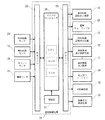
図6は上記弾球遊技機1の制御系のブロック構成を示すものであり、遊技制御装置19は、本弾球遊技機1に必要な遊技制御を行うワンチップのマイクロコンピュータ20と、発信器21と、入力インターフェイス22と、出力インターフェイス23とから主に構成されている。かかるマイクロコンピュータ20は、CPU、ROM、RAM等を内蔵しており、ICとして製造されるものである。
FIG. 6 shows a block configuration of the control system of the above-mentioned
マイクロコンピュータ20のCPUは、ROMに格納された遊技プログラム及び特図始動口9に配設された特図始動センサ24、普図始動ゲート10に配設された普図始動センサ25、大入賞口ユニット14に配設されたカウントセンサ26及び継続センサ27等からの信号に基づいて、遊技情報表示制御手段12に表示制御信号を送るとともに、特図始動記憶表示器15、普図始動記憶表示器16、電動チューリップ8を開閉させる駆動用ソレノイド28、大入賞口ユニット14のシャッタを開閉させる駆動用ソレノイド29、遊技における効果音の生成及び音声合成を行う音制御装置30、装飾用のランプや各種LEDを制御する装飾表示制御装置31に制御信号を出力する。
The CPU of the
然るに、遊技情報表示制御手段12には、遊技制御装置19からの表示制御信号に基づいて、遊技情報表示装置11の第1表示領域11aに特別図柄を変動表示させるとともに、第2表示領域11bに普通図柄を変動表示させるよう制御する。この時、境界部aの位置と表示装置カバー手段13における境界手段17の位置とが略同一となるよう予め設定しておく必要がある。
However, based on the display control signal from the game control device 19, the game information display control means 12 displays the special symbols in the
これにより、第1表示領域11a及び第2表示領域11bで表示される図柄は、いずれも遊技情報表示制御手段12によって制御されており、別個の表示装置及び制御装置が配設されたものに比べて、部品点数を削減することができる。尚、同図におけるマイクロコンピュータ20のCPUは、一定の周期毎にリセット割込を行って、その割込毎に遊技プログラムを予め定められた所定番地から実行するものである。
As a result, the symbols displayed in the
以上、本実施形態に係る弾球遊技機1について説明したが、本発明はこれに限定されるものではなく、例えば以下の如き構成とすることができる。即ち、表示装置カバー手段13に設けられる境界手段17は当該表示装置カバー手段13と別体としてもよく、この場合、境界手段17の固定位置が表示装置カバー手段13に対して調整可能とするのが好ましい。
The bullet
このように、境界手段17を上下に移動可能とすれば、境界部aの位置が変更された場合であっても、その位置に境界手段17を移動させ、当該境界部aの前面側を覆うようにすることができるので、表示領域の変化に合わせて境界手段17を移動させ境界部を覆うことができる。この場合の、境界手段17の移動手段としては、表示装置カバー手段13との間にLMガイド等を設けソレノイド等汎用アクチュエータにて当該境界手段17を移動させてもよいし、表示装置カバー手段13のいずれの位置にも境界手段17を脱着可能とし、所望位置に当該境界手段17を取り付けるようにしてもよい。 In this way, if the boundary means 17 can be moved up and down, even if the position of the boundary portion a is changed, the boundary means 17 is moved to that position and covers the front side of the boundary portion a. Therefore, the boundary means 17 can be moved in accordance with the change of the display area to cover the boundary portion. In this case, as the moving means of the boundary means 17, an LM guide or the like may be provided between the display apparatus cover means 13 and the boundary means 17 may be moved by a general-purpose actuator such as a solenoid. The boundary means 17 may be detachable at any position, and the boundary means 17 may be attached at a desired position.
また、図7に示すように、遊技情報表示装置11の表示領域を透視可能であって表示装置カバー手段13に着脱自在な窓板32に対し境界手段33を一体的に形成するよう構成してもよい。かかる窓板32はガラス又は透明樹脂で構成されるのが好ましく、図8に示すように、境界手段17を窓板32の所定位置にインサート成形にて造り込み、一体化させてもよいが、他の方法にて窓板32に境界手段17を設けてもよい。勿論、この場合であっても、境界手段17が遊技情報表示装置11の境界部aの前面側を覆って、当該境界部aを遊技者から視認し難くする必要がある。尚、第1表示領域11a及び第2表示領域11b毎に窓板を配設するようにしてもよい。
Further, as shown in FIG. 7, a boundary means 33 is formed integrally with a
本実施形態においては、遊技情報表示装置11における表示領域が上下に分割され境界手段が水平方向に延設されているが、本発明はこれに限定されず、図9に示すように、第1表示領域11aを左側、第2表示領域11bを右側に設定することにより垂直方向に延設された境界部a’を境界手段34で覆うよう構成してもよい。更に、遊技情報表示装置11における矩形状、三角形状、円形状の隅部、中央下部、又は中央上部を1つの表示領域とし、その表示領域と他の表示領域の境界部に沿って境界手段を設けるよう構成してもよい。尚、遊技情報表示装置11における表示領域を斜めに分割し、その領域の境界部に沿って境界手段を斜めに延設させてもよく、また、遊技情報表示装置11自体を斜めに配設して、その上下を第1表示領域11a及び第2表示領域11bと設定するようにしてもよい。
In the present embodiment, the display area in the game
尚、境界手段に特図始動記憶表示器15が設けられているが、これと共に普図始動記憶表示器16や、所定の遊技情報を表示する液晶表示装置、表示灯、ドットマトリックス表示装置、7セグメント表示装置等を当該境界手段に設けるよう構成してもよい。上記の場合であって各表示装置に表示すべき所定遊技情報としては、リーチ予告、スーパーリーチ予告、大当り予告、或いは確率変動予告に関する演出表示を行ってもよく、また、大当り確率、低確率状態での大当り確率、高確率状態での大当り確率或いは確率変動継続率等を表示するよう構成してもよい。
Although special symbol
また、図10に示すように、境界手段36の上面36aを遊技球が転がり得るステージとして構成してもよく、この場合、境界手段36の両端に対応する表示装置カバー手段13の側面に通過用孔35を形成しておき、遊技球が当該通過用孔35を介して境界手段36上に達し得るよう構成する。尚、境界手段36における上面36aの略中央部に同図の如き溝部36bを形成するのが好ましい。かかる構成によれば、遊技領域5における遊技球が通過用孔35を通過して境界手段36上に至ることにより溝部36bから落下し易くなっており、特図始動口9及び電動チューリップ8に入賞し易く構成することができる。
Further, as shown in FIG. 10, the
また更に、上記通過用孔35を介して遊技球を境界手段36の上面に誘導するための誘導部や境界手段36上における遊技球の転動に変化を与えるための部材(ジャマ板等)を設けるようにしてもよく、かかる遊技球の転動に変化を与えるための部材を可動にしてもよい。このように境界手段36の上面を遊技球が転動し得る構成の他、境界手段36の内部における少なくとも一部に遊技球が通過可能な通過孔又は通過樋を形成してもよく、かかる通過孔又は通過樋の前面側に遊技球の通過を遊技者が視認し得る透明部材又は透視用孔(複数であってもよい)を設けて構成してもよい。
Still further, a guiding portion for guiding the game ball to the upper surface of the boundary means 36 through the
ここで、本実施形態及び上記他の実施形態においては、第1表示領域11aに第1図柄としての特別図柄(第1始動検出、即ち遊技球の特図始動口9への通過を条件に可変表示される図柄)、第2表示領域11bに第2図柄としての普通図柄(第2始動検出、即ち遊技球の普図始動ゲート10への通過を条件に可変表示される図柄)を表示することとしているが、本発明はこれに限定されず、以下の構成としてもよい。
Here, in the present embodiment and the other embodiments described above, the
例えば、第1表示領域11a又は第2表示領域の少なくとも一方において、所定の演出表示や広告表示をさせるよう構成してもよい。このうち演出表示とは、演出効果を目的に表示される種々の表示をいい、例えば、所定のキャラクタを常時動画として表示させておくこともできる。また、第1表示領域11a又は第2表示領域の少なくとも一方において、大当りラウンド数、特定領域通過情報、大入賞口入賞個数等の大当り中の演出表示、大当り確率、低確率状態での大当り確率、高確率状態での大当り確率、確率変動継続率、回数切り確率変動の最大回数の表示、或いは電源投入後の大当り回数・確率変動回数、大当り発生からの回転数等の表示を行うこともできる。
For example, you may comprise so that a predetermined | prescribed effect display and advertisement display may be carried out in at least one of the
尚、このような演出表示は、特別図柄や普通図柄と連動して表示されるものであっても、これら図柄と無関係に表示されるものであってもよく、第1表示領域11a又は第2表示領域のいずれかに表示される他、表示装置カバー手段13に形成される境界手段(17、33、34、36)に液晶等の画面を形成しておき、そこで表示させるよう構成してもよい。更に、第1表示領域11a及び第2表示領域の夫々にデモンストレーションを表示させたり、第1表示領域11a又は第2表示領域の少なくとも一方は、他方の表示領域において複数回図柄が変動して確定表示する間に演出表示をするよう構成してもよい。このように、境界手段に各種電製品を具備させるべく、当該境界手段における内部の少なくとも一部に配線が通過可能な配線通過孔又は樋を設けるように構成してもよい。
Such an effect display may be displayed in conjunction with a special symbol or a normal symbol, or may be displayed independently of these symbols, and may be displayed in the
ここで、本発明は、いずれの弾球遊技機に対しても適用することが可能であり、上記実施形態の如き第1種パチンコ遊技機の他、第2種及び第3種パチンコ遊技機、アレンジボール遊技機、及び雀球遊技機において配設された遊技情報表示装置に適用することもできる。例えば、アレンジボール遊技機に適用する場合、次に示すような構成とすることができる。 Here, the present invention can be applied to any ball game machine, and in addition to the first type pachinko gaming machine as in the above embodiment, the second type and third type pachinko gaming machine, The present invention can also be applied to game information display devices arranged in arrange ball game machines and sparrow ball game machines. For example, when applied to an arrangement ball gaming machine, the following configuration can be adopted.
一般に、アレンジボール遊技機は、以下の如き構成要素を含む。即ち、遊技領域へ単位ゲーム毎に所定個数の遊技球を順次発射可能な発射装置と、遊技球が通過可能な複数の入球口と、該複数の入球口への遊技球の入球を夫々検出する複数の入球検出手段と、複数の入球口に対応する複数の表示部を含み、遊技球が通過した入球口に対応する表示部が遊技球の通過以前と異なる特定表示に変化する入球表示手段と、該入球表示手段の特定表示となった表示部が特定の組み合わせとなった場合にその種類に応じて所定数の遊技媒体を払い出す払出装置と、前記特定の組み合わせの種類に応じて所定の得点を表示する得点表示手段と、始動手段が遊技球を検出することを条件に1又は複数の図柄を変動表示する図柄表示手段と、該図柄表示手段に表示される停止図柄の態様が特定図柄の態様となる場合に遊技球の入賞が可能である状態に解法される特定入賞口と、前記特定入賞口内の特定領域を通過する遊技球を検出する球通過検出手段と、前記特定領域を遊技球が通過することを条件に遊技者に有利な状態を発生する特別遊技発生手段と、前記発射手段が発射する遊技球を検出する発射球検出手段と、前記発射手段が発射した遊技球のうち遊技領域まで達せずに回収された遊技球を検出する戻り球検出手段と、前記複数の入賞口及び特定入賞口のうち予め定められた入賞口に遊技球が入球することを条件に前記払出手段が前記特定の組み合わせの種類に応じて払い出す遊技媒体を増加させる払出増加手段と、前記所定個数の遊技球が前記複数の入賞口に入賞することを条件に当該ゲームを終了させ精算処理を行うゲーム精算手段とを備える。 Generally, an arrangement ball gaming machine includes the following components. That is, a launching device capable of sequentially firing a predetermined number of game balls for each unit game into the game area, a plurality of entrances through which the game balls can pass, and entrance of game balls into the plurality of entrances It includes a plurality of entrance detection means for detecting each and a plurality of display units corresponding to the plurality of entrances, and the display unit corresponding to the entrance through which the game ball has passed has a specific display different from that before the game ball has passed. A changing entry display means, a payout device for paying out a predetermined number of game media according to the type when the display unit which is a specific display of the entry display means is a specific combination, and the specific display Displayed on a symbol display means for displaying a predetermined score according to the type of combination, a symbol display means for variably displaying one or more symbols on the condition that the starting means detects a game ball, and displayed on the symbol display means A game ball when the stop symbol is a specific symbol The game is performed on condition that the specific winning opening solved in a state where a winning is possible, the ball passage detecting means for detecting the game ball passing through the specific area in the specific winning opening, and the game ball passing through the specific area A special game generating means for generating a state advantageous to a person, a fire ball detecting means for detecting a game ball launched by the launch means, and a game ball of the game balls launched by the launch means that has been collected without reaching the game area Returning ball detecting means for detecting a game ball, and the payout means as a type of the specific combination on condition that a gaming ball enters a predetermined winning port among the plurality of winning ports and a specific winning port A payout increasing means for increasing the game medium to be paid out in response to the game payout means and a game checkout means for ending the game and performing a checkout process on condition that the predetermined number of game balls win the plurality of winning holes.
そして、入賞表示手段に表示される入賞図柄、図柄表示手段に表示される誘導図柄、及び得点表示手段に表示される得点や、発射手段から発射された遊技球の数(発射球数)、入賞口への入球数、特別遊技発生手段による遊技者に有利な状態の発生の有無、及び払出増加手段による作動の有無のうち任意のものを第1表示領域及び第2表示領域にそれぞれ表示させるようにして本発明を適用させてもよい。即ち、入賞表示手段、得点表示手段、図柄表示手段で表示すべき情報やその他の各種遊技情報を各表示領域に表示させるとともに、その境界部を境界手段で覆って、遊技者側に対して別個の表示であることを明確にすることができる。 Then, a winning symbol displayed on the winning display means, a guide symbol displayed on the symbol displaying means, a score displayed on the score displaying means, the number of game balls fired from the launching means (number of firing balls), a winning prize Any one of the number of balls entering the mouth, the presence / absence of a state advantageous to the player by the special game generating means, and the presence / absence of the operation by the payout increasing means is displayed in the first display area and the second display area, respectively. Thus, the present invention may be applied. That is, information to be displayed by the winning display means, the score display means, the symbol display means and other various game information are displayed in each display area, and the boundary portion is covered by the boundary means, and is separately provided to the player side. It can be clearly shown that
1…弾球遊技機
2…遊技盤
3…操作ハンドル
4…ガイドレール
5…遊技領域
6…アウト穴
7…一般入賞装置
8…電動チューリップ
9…特図始動口
10…普図始動ゲート
11…遊技情報表示装置
11a…第1表示領域
11b…第2表示領域
12…遊技情報表示制御手段
13…表示装置カバー手段
14…大入賞口ユニット
15…特図始動記憶表示器
16…普図始動記憶表示器
17、33、34、36…境界手段
18…裏カバー
19…遊技制御装置
20…マイクロコンピュータ
21…発振器
22…入力インターフェイス
23…出力インターフェイス
24…特図始動センサ
25…普図始動センサ
26…カウントセンサ
27…継続センサ
28…電動チューリップ8のソレノイド
29…大入賞口ユニット14のソレノイド
30…音制御装置
31…装飾表示制御装置
32…窓板
35…通過用孔
36a…上面(ステージ)
36b…溝部
a…境界部
DESCRIPTION OF
36b ... groove a ... boundary
Claims (1)
該遊技情報表示装置による表示領域への表示を制御する遊技情報表示制御手段と、
遊技球が通過したことを条件に、前記遊技情報表示装置の表示領域で図柄を可変表示させる始動口又は始動ゲートと、
を備えた弾球遊技機において、
前記遊技情報表示装置は、その単一の表示領域が少なくとも第1表示領域と、第2表示領域とに区画され、前記始動口又は始動ゲートを遊技球が通過したことを条件に当該第1表示領域又は第2表示領域で図柄を可変表示させるとともに、当該遊技情報表示装置の前面側には、前記第1表示領域と第2表示領域との境界部に沿って延びた境界手段が設けられ、境界手段には、第1表示領域又は第2表示領域の図柄が変動している間に、遊技球が前記始動口又は始動ゲートを何個通過したのかを表示するためのLEDから成る始動記憶表示器が形成されたことを特徴とする弾球遊技機。 A game information display device having a display area for displaying predetermined game information;
Game information display control means for controlling display on the display area by the game information display device;
A starting port or a starting gate for variably displaying a symbol in the display area of the gaming information display device, on condition that the game ball has passed;
In a ball game machine equipped with
The game information display device includes a single display area is at least a first display area thereof, is partitioned into a second display area, the first display on the condition that the starting opening or game balls starting gate has passed In addition to displaying the symbols variably in the area or the second display area, boundary means extending along the boundary between the first display area and the second display area is provided on the front side of the game information display device. The boundary means includes a start memory display composed of LEDs for displaying how many game balls have passed through the start port or start gate while the design of the first display area or the second display area is fluctuating. A ball game machine characterized in that a vessel is formed.
Priority Applications (1)
| Application Number | Priority Date | Filing Date | Title |
|---|---|---|---|
| JP2005173713A JP4467472B2 (en) | 2005-06-14 | 2005-06-14 | Bullet ball machine |
Applications Claiming Priority (1)
| Application Number | Priority Date | Filing Date | Title |
|---|---|---|---|
| JP2005173713A JP4467472B2 (en) | 2005-06-14 | 2005-06-14 | Bullet ball machine |
Related Parent Applications (1)
| Application Number | Title | Priority Date | Filing Date |
|---|---|---|---|
| JP2001221590A Division JP3737719B2 (en) | 2001-07-23 | 2001-07-23 | Bullet ball machine |
Related Child Applications (2)
| Application Number | Title | Priority Date | Filing Date |
|---|---|---|---|
| JP2005359456A Division JP4271184B2 (en) | 2005-12-13 | 2005-12-13 | Bullet ball machine |
| JP2005359455A Division JP4271183B2 (en) | 2005-12-13 | 2005-12-13 | Bullet ball machine |
Publications (3)
| Publication Number | Publication Date |
|---|---|
| JP2005261982A JP2005261982A (en) | 2005-09-29 |
| JP2005261982A5 JP2005261982A5 (en) | 2006-02-02 |
| JP4467472B2 true JP4467472B2 (en) | 2010-05-26 |
Family
ID=35087085
Family Applications (1)
| Application Number | Title | Priority Date | Filing Date |
|---|---|---|---|
| JP2005173713A Expired - Fee Related JP4467472B2 (en) | 2005-06-14 | 2005-06-14 | Bullet ball machine |
Country Status (1)
| Country | Link |
|---|---|
| JP (1) | JP4467472B2 (en) |
Families Citing this family (1)
| Publication number | Priority date | Publication date | Assignee | Title |
|---|---|---|---|---|
| JP5284752B2 (en) * | 2008-10-22 | 2013-09-11 | 京楽産業.株式会社 | Pachinko machine |
Family Cites Families (7)
| Publication number | Priority date | Publication date | Assignee | Title |
|---|---|---|---|---|
| JPH08117416A (en) * | 1994-10-26 | 1996-05-14 | Sankyo Kk | Game machine |
| JPH08173607A (en) * | 1994-12-21 | 1996-07-09 | Sankyo Kk | Game machine |
| JP3106092B2 (en) * | 1995-06-19 | 2000-11-06 | 株式会社三共 | Gaming machine |
| JP2000107377A (en) * | 1998-10-08 | 2000-04-18 | Daiichi Shokai Co Ltd | Ball game machine |
| JP4089855B2 (en) * | 1999-12-20 | 2008-05-28 | 株式会社ソフィア | Game machine |
| JP2001300062A (en) * | 2000-04-27 | 2001-10-30 | Olympia:Kk | Game machine |
| JP2001157753A (en) * | 2000-12-13 | 2001-06-12 | Sanyo Product Co Ltd | Game machine |
-
2005
- 2005-06-14 JP JP2005173713A patent/JP4467472B2/en not_active Expired - Fee Related
Also Published As
| Publication number | Publication date |
|---|---|
| JP2005261982A (en) | 2005-09-29 |
Similar Documents
| Publication | Publication Date | Title |
|---|---|---|
| JP6438499B2 (en) | Game machine | |
| JP2008073299A (en) | Game machine | |
| JP2011110315A (en) | Game machine | |
| JP2008253643A (en) | Game machine | |
| JP2017189286A (en) | Game machine | |
| JP3737719B2 (en) | Bullet ball machine | |
| JP4014196B2 (en) | Bullet ball machine | |
| JP2005237616A (en) | Pachinko game machine | |
| JP5001709B2 (en) | Game machine | |
| JP4261527B2 (en) | Game machine | |
| JP4467472B2 (en) | Bullet ball machine | |
| JP2008194246A (en) | Game machine, program, and storage medium | |
| JP2008229129A (en) | Game machine | |
| JP4271183B2 (en) | Bullet ball machine | |
| JP4271184B2 (en) | Bullet ball machine | |
| JP2016198678A5 (en) | ||
| JP5240580B2 (en) | Pachinko machine | |
| JP5186536B2 (en) | Bullet ball machine | |
| JP2006095162A (en) | Game machine | |
| JP2005124940A (en) | Game machine | |
| JP5548734B2 (en) | Game machine | |
| JP2023015935A (en) | game machine | |
| JP2023015934A (en) | game machine | |
| JP4944530B2 (en) | Game machine | |
| JPH11244483A (en) | Game machine |
Legal Events
| Date | Code | Title | Description |
|---|---|---|---|
| A521 | Written amendment |
Free format text: JAPANESE INTERMEDIATE CODE: A523 Effective date: 20051213 |
|
| A621 | Written request for application examination |
Free format text: JAPANESE INTERMEDIATE CODE: A621 Effective date: 20051219 |
|
| A131 | Notification of reasons for refusal |
Free format text: JAPANESE INTERMEDIATE CODE: A131 Effective date: 20081209 |
|
| A521 | Written amendment |
Free format text: JAPANESE INTERMEDIATE CODE: A523 Effective date: 20090123 |
|
| A131 | Notification of reasons for refusal |
Free format text: JAPANESE INTERMEDIATE CODE: A131 Effective date: 20090220 |
|
| A521 | Written amendment |
Free format text: JAPANESE INTERMEDIATE CODE: A523 Effective date: 20090408 |
|
| A131 | Notification of reasons for refusal |
Free format text: JAPANESE INTERMEDIATE CODE: A131 Effective date: 20090430 |
|
| A521 | Written amendment |
Free format text: JAPANESE INTERMEDIATE CODE: A523 Effective date: 20090616 |
|
| A02 | Decision of refusal |
Free format text: JAPANESE INTERMEDIATE CODE: A02 Effective date: 20090831 |
|
| A521 | Written amendment |
Free format text: JAPANESE INTERMEDIATE CODE: A523 Effective date: 20091111 |
|
| A911 | Transfer of reconsideration by examiner before appeal (zenchi) |
Free format text: JAPANESE INTERMEDIATE CODE: A911 Effective date: 20091207 |
|
| TRDD | Decision of grant or rejection written | ||
| A01 | Written decision to grant a patent or to grant a registration (utility model) |
Free format text: JAPANESE INTERMEDIATE CODE: A01 Effective date: 20100222 |
|
| A01 | Written decision to grant a patent or to grant a registration (utility model) |
Free format text: JAPANESE INTERMEDIATE CODE: A01 |
|
| A61 | First payment of annual fees (during grant procedure) |
Free format text: JAPANESE INTERMEDIATE CODE: A61 Effective date: 20100223 |
|
| R150 | Certificate of patent or registration of utility model |
Ref document number: 4467472 Country of ref document: JP Free format text: JAPANESE INTERMEDIATE CODE: R150 Free format text: JAPANESE INTERMEDIATE CODE: R150 |
|
| FPAY | Renewal fee payment (event date is renewal date of database) |
Free format text: PAYMENT UNTIL: 20130305 Year of fee payment: 3 |
|
| FPAY | Renewal fee payment (event date is renewal date of database) |
Free format text: PAYMENT UNTIL: 20130305 Year of fee payment: 3 |
|
| FPAY | Renewal fee payment (event date is renewal date of database) |
Free format text: PAYMENT UNTIL: 20140305 Year of fee payment: 4 |
|
| R250 | Receipt of annual fees |
Free format text: JAPANESE INTERMEDIATE CODE: R250 |
|
| R250 | Receipt of annual fees |
Free format text: JAPANESE INTERMEDIATE CODE: R250 |
|
| R250 | Receipt of annual fees |
Free format text: JAPANESE INTERMEDIATE CODE: R250 |
|
| R250 | Receipt of annual fees |
Free format text: JAPANESE INTERMEDIATE CODE: R250 |
|
| R250 | Receipt of annual fees |
Free format text: JAPANESE INTERMEDIATE CODE: R250 |
|
| R250 | Receipt of annual fees |
Free format text: JAPANESE INTERMEDIATE CODE: R250 |
|
| LAPS | Cancellation because of no payment of annual fees |